Article

Neural Network-Based Autonomous Search Model with Undulatory Locomotion Inspired by Caenorhabditis Elegans

National Laboratory of Radar Signal Processing, Xidian University, Xi’an 710071, China
*
Author to whom correspondence should be addressed.
Sensors 2022, 22(22), 8825; https://doi.org/10.3390/s22228825
Submission received: 18 October 2022 / Revised: 10 November 2022 / Accepted: 12 November 2022 / Published: 15 November 2022
(This article belongs to the Special Issue Mobile Robots: Navigation, Control and Sensing)

Abstract

:
Caenorhabditis elegans (C. elegans) exhibits sophisticated chemotaxis behavior with a unique locomotion pattern using a simple nervous system only and is, therefore, well suited to inspire simple, cost-effective robotic navigation schemes. Chemotaxis in C. elegans involves two complementary strategies: klinokinesis, which allows reorientation by sharp turns when moving away from targets; and klinotaxis, which gradually adjusts the direction of motion toward the preferred side throughout the movement. In this study, we developed an autonomous search model with undulatory locomotion that combines these two C. elegans chemotaxis strategies with its body undulatory locomotion. To search for peaks in environmental variables such as chemical concentrations and radiation in directions close to the steepest gradients, only one sensor is needed. To develop our model, we first evolved a central pattern generator and designed a minimal network unit with proprioceptive feedback to encode and propagate rhythmic signals; hence, we realized realistic undulatory locomotion. We then constructed adaptive sensory neuron models following real electrophysiological characteristics and incorporated a state-dependent gating mechanism, enabling the model to execute the two orientation strategies simultaneously according to information from a single sensor. Simulation results verified the effectiveness, superiority, and realness of the model. Our simply structured model exploits multiple biological mechanisms to search for the shortest-path concentration peak over a wide range of gradients and can serve as a theoretical prototype for worm-like navigation robots.

1. Introduction

Biological systems are important inspirational resources for mobile-robot control research. Even the simplest organisms have unique locomotion patterns and remarkable spatial orientation abilities, which depend on their powerful nervous systems. The nematode Caenorhabditis elegans (C. elegans) has a small, compact anatomy, a fully mapped nervous system comprising only 302 neurons [1,2], and a rich behavioral repertoire; thus, it is an ideal organism for linking neural activity to behavior. ‘C. elegans moves in an undulatory fashion by generating sinusoidal dorsoventral bends that propagate from anterior to posterior; the locomotion is involved in most, if not all, of its behavior. Furthermore, C. elegans exhibits chemotaxis toward numerous environmental cues, including salt; chemotaxis is the ability to move up (or down) a concentration gradient of a chemical attractant (or repellent). In C. elegans, chemotaxis is performed using two parallel strategies [3]: klinokinesis and klinotaxis. Klinokinesis [4] is a biased random walk in which sharp turns occur more frequently in response to a declining (or rising) concentration gradient. The klinotaxis strategy [3] gradually adjusts the movement direction toward the line of steepest ascent (or descent) within the gradient. These behaviors can also be important functions for mobile robots. Chemotaxis-inspired navigation methods can control robots to perform specific tasks, such as chemical leak location [5,6]; radiation measurement [7]; and environment monitoring [8]. Worm-like undulation robots can be deployed in certain special scenarios, such as in pipelines [9] and complex terrain [10,11].
From an engineering perspective, the C. elegans chemotaxis behavior is attractive for robotic navigation control. First, this is because the two chemotaxis strategies serve complementary roles to ensure a short search path. Klinokinesis allows the robot to use temporal gradients of environmental variables to quickly correct its direction away from the target, while klinotaxis allows the robot to gradually optimize the path using spatial gradients to align its movement with the steepest gradient direction. Second, C. elegans performs chemotaxis only by sensing concentration changes at a single point in its head, suggesting that a robot could mimic the two chemotaxis strategies with a single sensor. This is reasonable, especially for small or resource-constrained mobile robots, as it enables them to make precise steering decisions according to temporal and spatial gradients while carrying a single sensor. Moreover, the clearly delineated nervous system of C. elegans provides researchers with the opportunity to study the functional neural circuits [12,13,14] and mechanisms underlying these behaviors [15,16,17,18]. Therefore, these behaviors can be replicated using simple models with efficient biological neural mechanisms, and such models could potentially incorporate these biological methods into robot control applications.
Several studies have explored navigation models inspired by chemotaxis locomotion in C. elegans. In early works, researchers [19,20,21] simulated chemotaxis behavior using recurrent networks; hence, they explored computational rules and behavioral strategies for chemotaxis in C. elegans. Additionally, Morse et al. [22] designed an autonomous robot to perform chemotaxis-like phototaxis behavior under the control of a simulated neural network. Xu et al. [23] trained dynamic neural networks with single or dual sensory neurons to perform navigation tasks featuring salt attraction and toxin avoidance, mimicking the klinokinesis or klinotaxis strategy; subsequently, those researchers added a speed regulation mechanism to their model [24]. Some studies focused on implementing C. elegans chemotaxis-inspired contour tracking by designing spiking neural networks [25,26] and utilizing a neuromorphic processor [27]. However, in the above works, each model was regarded as a point, and the whole-body movement of C. elegans was ignored. Deng et al. [28] incorporated the body undulatory locomotion of C. elegans into a navigation model emulating chemotaxis for the first time; however, the wave propagation was modeled using an added phase lag term, which was unrealistic, and navigation-induced head deflections could not be propagated. A follow-up study [29] further incorporated the proprioception mechanism [15,30], which is a biological mechanism responsible for the propagation of undulatory waves along the body in C. elegans. Demin et al. [31] and Costalago-Meruelo et al. [32] both trained neural circuit models and combined physics engines to simulate chemotaxis and body locomotion in C. elegans.
Existing models typically leverage one strategy only. Most (i.e., [19,20,21,22,23,24,25,26,27,28,29,31]) imitate klinokinesis; the model decides to turn or continue straight based on the temporal gradients of the environmental variables only and, therefore, a short search path cannot be guaranteed. Other models (i.e., [23,24,32]) mimic klinotaxis exclusively; they steer in the correct direction depending on the spatial gradient perpendicular to their current path, but usually under the assumption that two sensors are spaced at a certain distance to directly determine the spatial gradient. However, biological studies [14,33] have found that ASEL and ASER neurons in C. elegans are responsible for sensing salt, and function by sensing concentration changes at a single point in the head due to proximity. The state-dependent gating neural mechanism [34,35] indicates that the klinotaxis steering response of C. elegans relies on the internal state of the nervous system at the time of the sensory stimulus during undulatory locomotion. Our previous work [17] further identified this mechanism in a neural model based on the C. elegans connectome.
Thus, owing to the omission of one chemotaxis strategy, current C. elegans-inspired navigation models are often unable to use the temporal and spatial gradient information simultaneously to rapidly search for a gradient source in the environment. In particular, current models typically lack the ability to capture spatial gradient information with a single sensor. To address this problem, we designed a bio-inspired network model that integrates the two strategies (i.e., klinokinesis and klinotaxis) and body undulatory locomotion of C. elegans in the context of one sensor. The model exploits the advantages of the complete C. elegans chemotaxis behavior, aiming to provide an efficient robotic autonomous search scheme and afford a simple network control prototype for worm-like navigation robots. The proposed model is a multi-joint rigid link system with a network circuit that controls the joint angles. To implement complex behavior in this simple model, we simplified the network circuit as much as possible based on the functional neural circuits of C. elegans and incorporated multiple biological mechanisms. The main contributions of this study are as follows.
First, a central pattern generator (CPG) was evolved using a genetic algorithm (GA) to spontaneously generate rhythmic oscillatory signals. Furthermore, a repeating minimal network unit with proprioceptive feedback was designed, which is sufficient to propagate the undulatory wave from anterior to posterior. As such, the model can perform realistic body undulatory locomotion during both forward and navigation-induced steering movements; this behavior was verified through simulation experiments.
Second, dynamic adaptive sensory neuron models were constructed based on the electrophysiological characteristics of the salt sensory neurons in C. elegans, which convert information from the sensor into the sensory inputs of the network circuit. Moreover, the state-dependent gating mechanism was incorporated into the model, thereby realizing klinotaxis behavior in the context of a single sensor. Klinokinesis behavior is implemented by fitting a logic function. The model can make steering decisions leveraging the klinotaxis and klinokinesis strategies simultaneously; klinokinesis allows for rapid steering away from the target, while klinotaxis continuously adjusts the movement direction toward the side with the higher concentration. The model was tested in simulations, demonstrating its stable search for environmental variable peaks in directions close to the steepest gradients over a wide range of gradients. The search path was significantly shorter than those of the models employing a single strategy. In addition, the quantitative analysis verified the realness of the two strategies implemented by the proposed model.
The remainder of this paper is organized as follows. Section 2 details the proposed methodology; the overall model architecture and biological basis are first introduced and a detailed description of the sub-network circuits controlling the undulatory locomotion and navigation behavior is then provided. Section 3 presents the experiment results and corresponding analyses, and comparative discussion. Section 4 summarizes the study and suggests future research.

2. Methodology

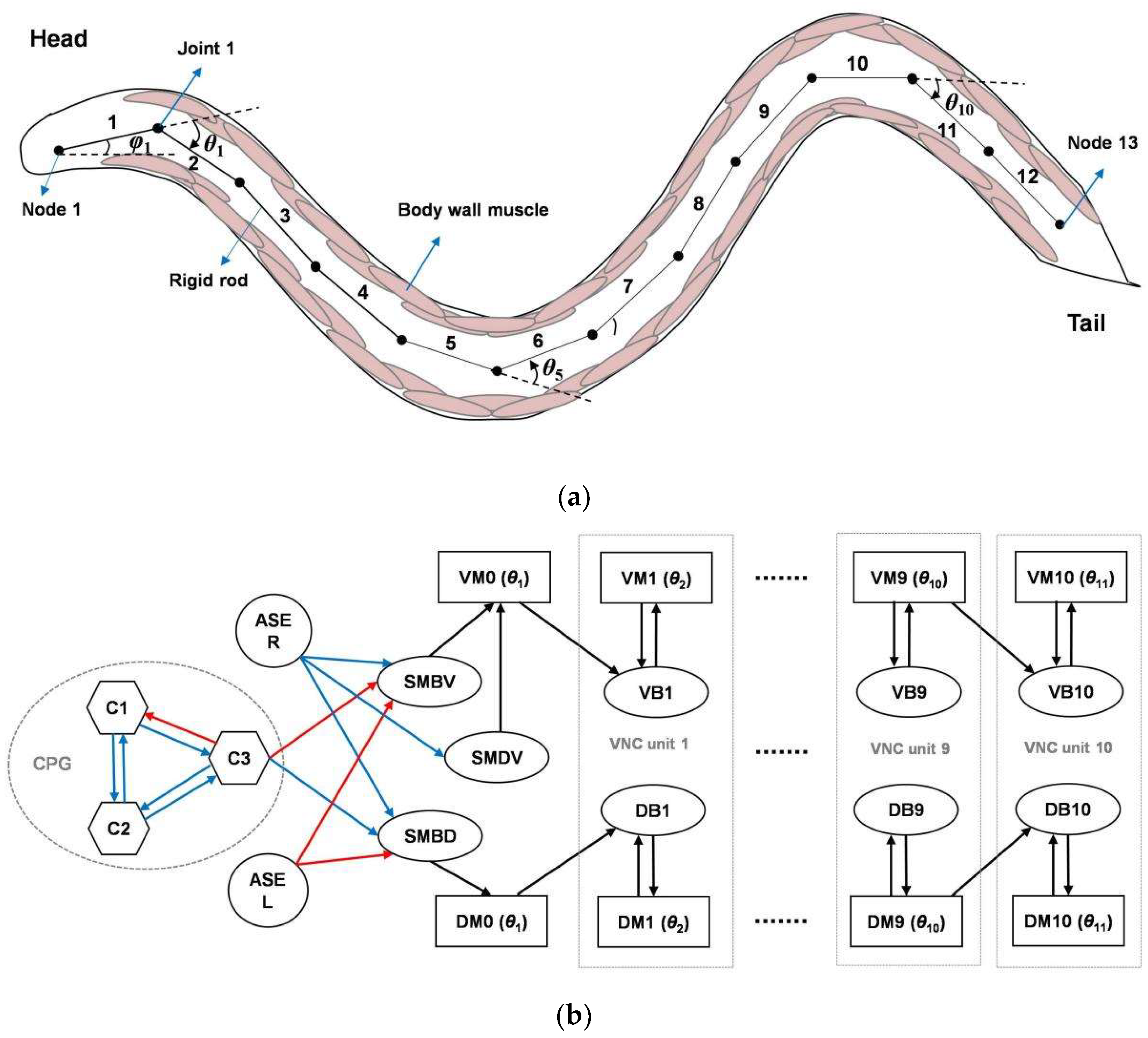
2.1. Overall Model Architecture and Biological Basis

The overall model architecture consists of a multi-joint rigid link system and a simple network circuit based on the anatomical structure and functional neural circuits of C. elegans, as shown in Figure 1. C. elegans is approximately 1 mm long and elliptically cylindrical in shape. It moves on its side on agar and bends in the dorsoventral plane [36], with this movement being mediated by a neuromuscular circuit. Its 95 body wall muscles are arranged along the four body quadrants [37]: the dorsal left, dorsal right, ventral left, and ventral right (DL, DR, VL, and VR, respectively). Each quadrant contains 24 or 23 muscles, which are staggered in pairs. Based on its muscle structure, C. elegans was typically modeled with 11 or 12 segments in previous works [28,29]. Similarly, our model contains 12 rigid rods of length l, with 11 rotatable joints and 13 nodes, as shown in Figure 1a. Joint 1 controls the head orientation and Node 1 corresponds to the head tip.
The C. elegans neural circuits for navigation locomotion are well understood. The motoneurons located in the head and along the ventral neural cord (VNC) drive the dorsoventral muscles to contract and relax rhythmically, generating undulatory locomotion with sinusoidal body waves. Laser ablation studies [13] have shown that, among the five types of VNC motoneurons, the cholinergic B-type excitatory motoneurons are essential for forward locomotion; these include 11 ventral B-type motoneurons (VB neurons) and seven dorsal B-type motoneurons (DB neurons) that form neuromuscular junctions with ventral and dorsal muscle cells, respectively. The four SMB-class and four SMD-class head motoneurons [12] play important roles in regulating the undulatory amplitude and sharp turns, respectively, and innervate the head and neck muscles. In the salt-sensorimotor pathway of C. elegans, asymmetric chemosensory neurons (ASEL/R) [14,33] located in the head sense salt stimuli in the environment and communicate with motoneurons through interneurons, inducing head steering. Based on this understanding, we designed a simplified network circuit, the outputs of which control the joint angles of the rigid link system. As shown in Figure 1b, the circuit consists of a head circuit responsible for generating undulations and making navigation decisions, and 10 repeating minimal VNC units responsible for wave propagation. Because this model is two-dimensional, the muscles degenerate to the dorsal and ventral muscles (DMs and VMs, respectively). In addition, the head circuit contains a CPG; however, it is still unclear which neurons belong to the CPG in the head of C. elegans.

2.2. Definitions

For clarity, some definitions of the kinematics-related terms used in this study are shown in Figure 2. Unless otherwise specified, the position and locomotion trajectory of the model default to those of the head tip (i.e., Node 1 of the rigid link system). Because the model performs undulatory locomotion, the translation direction is the forward direction of the model during movement for one cycle. The normal direction is that 90° counterclockwise to the translation direction. The instantaneous locomotion direction can be decomposed into a translation component and a perpendicular component (the same or opposite to the normal direction). The turning bias is the angle between the current translation direction and the translation direction after one cycle. Sides D and V correspond to the left and right sides, respectively, and a left/right sweep corresponds to half a cycle of movement toward the right/left.

2.3. Undulatory Control Circuit

The key to realizing undulatory locomotion is the generation and propagation of an undulatory wave, which requires encoding of rhythmic oscillatory signals in both temporal sequences and spatial patterns. For simplicity, we designed an undulatory control circuit in accordance with the biological view [15,38] that a single CPG produces head-bending waves in C. elegans, and that these waves propagate through body from anterior to posterior via proprioceptive feedback. Note, however, that the existence of multiple oscillators in the mid-body VNC motor circuit of C. elegans has been suggested [16,39].

2.3.1. CPG

CPGs are neuronal circuits capable of producing rhythmic outputs without rhythmic inputs, typically as a result of reciprocal inhibitory interactions between neurons. Biomimetic CPG controllers are often used in rhythmic motion robots [40,41]. In the proposed model, the CPG consists of three interconnected dynamic neurons (i.e., C1, C2, and C3). In previous models [28,29], a sinusoidal voltage was preassigned to a neuron (i.e., as an oscillator) and the CPG neuron phases were regulated through neuronal interactions. In contrast, we made no explicit a priori assumption regarding the way neurons generate oscillations and evolved them to spontaneously generate oscillatory voltages. This mechanism is more in line with biological reality, and from an engineering perspective, the design of a specialized neuron with sinusoidal oscillations is not required.
The neurons in the CPG have first-order nonlinear dynamics, which are expressed by the following first-order ordinary differential equation (ODE):
τ i d V i ( t ) d t = ( V i E i r e s t ) + j w i , j f ( V j + b j ) ,
where V i ( t ) denotes the voltage of neuron i at time t, τ is the time constant, and Erest is the resting potential. The second term on the right is the input current from the other neurons, where w i , j represents the connection weight from neuron j to i, b is the constant bias, and f ( ) is a sigmoidal function that expresses the nonlinear transmission from the presynaptic neurons to the postsynaptic neurons.
In the proposed model, a simple evolutionary algorithm known as the genetic algorithm (GA) [42] evolves the CPG parameters. There are 15 parameters to be determined: τi [0.05, 2]; w i , j [−10, 10]; E i r e s t [−10, 10]; bi [−10, 10] (the values in square brackets are the ranges). The parameters are encoded as a real-valued vector with a range of [−1, 1], which corresponds to one individual. The initial population is composed of 500 random individuals and evolves into a new population generation through crossover, mutation, and selection operations. During crossover, two individuals are randomly selected as parents and a new individual, the child, is obtained through two-point recombination. The child is then mutated by adding Gaussian noise with mean zero and a standard deviation (s.d.) of 0.2 to each element of the vector. During selection, the parent with the lower fitness is selected and replaced with the child. If 300 generations are obtained, or the fitness of the best individual exceeds the threshold, the iteration ends.
The goal of this evolution is for the CPG output neuron C3 to generate a sinusoidal oscillatory voltage with a cycle of T o s c = 4   s (approximating the C. elegans cycle recorded in biological data [35]). Therefore, the model employs the fitness function F, which is the product of multiple components: F = F 1 F 2 F 3 , in terms of V C 3 ( t ) , and
F 1 = 1 | 1 T 0 T V C 3 ( t ) d t | ,
F 2 = f N ( max ( V C 3 ( t ) ) , min ( V C 3 ( t ) ) ) ,
F 3 = f N ( 1 T 0 T | d V C 3 ( t ) d t | d t ,   4 max ( V C 3 ( t ) ) T o s c ) ,
where T is the time length and f N ( x , x 0 ) = ( x / x 0 ) exp ( 1 x / x 0 ) is a normalization function that reaches a maximum of 1 at x = x0. Here, F1 is combined with F2 to reward voltage dynamics with zero mean and with the same positive and negative amplitudes. Hence, the same left–right sweep amplitude is ensured for the undulatory locomotion; that is, the translation direction is straight. F3 is an oscillatory criterion that encourages the voltage change rate to match that of the ideal sinusoidal function, with reference to the criterion used in [43]. The negative values for these functions are set to zero.
The specific amplitude of the voltage is not specified in the evolution, because the output strength can be tuned by connection weights. In addition, some evolved solutions may exhibit damped oscillations that must be re-evaluated over a longer period. Finally, the best individual with stable oscillation is selected from the multiple solutions evolved by the GA to form the CPG.

2.3.2. Undulation Generation and Propagation

As shown in Figure 1b, the SMBD and SMBV motoneurons receive antiphase oscillatory inputs from neuron C3, with the same connection weight strengths but opposite algebraic signs. For simplicity, SMBD and SMBV are modeled as neurons with a linear synaptic transfer function, and their voltage dynamics are expressed by the following ODE:
τ S M B d V S M B D / V ( t ) d t = ( V S M B D / V ( t ) E S M B r e s t ) + w S M B D / V , C 3 V C 3 ( t ) +   w S M B , A S E L V A S E L ( t ) + w S M B , A S E R V A S E R ( t )
The symbols have the same meanings as in Equation (1), except that the subscripts refer to different neurons; thus, the definitions are not repeated here. w S M B D , C 3 = w S M B V , C 3 > 0 , and the other SMBD and SMBV parameters are set to the same values. Here, we default to zero sensory input from ASEL/R; this setting is discussed below.
When affected by oscillatory inputs, SMBD and SMBV generate oscillatory voltages with opposite phases, which are in turn fed to muscles DM0 and VM0, respectively, via excitatory neuromuscular junctions. The DM0 and VM0 activation states are expressed as follows:
τ A 0 d A D M 0 ( t ) d t = A D M 0 ( t ) + w M 0 , S M B m V S M B D ( t ) ,
τ A 0 d A V M 0 ( t ) d t = A V M 0 ( t ) + w M 0 , S M B m V S M B V ( t ) + w M 0 , S M D m V S M D V ( t ) ,
where A i ( t ) denotes the activation state of muscle i at time t and w M 0 , S M B m > 0 is the neuromuscular junction weight from SMBD/V to D/VM0. In addition, VM0 also receives input from SMDV with w M 0 , S M D m > 0 ; this mechanism is related to the navigation function, as discussed below.
The angle of Joint 1 is controlled by the difference between the nonlinear outputs of DM0 and VM0:
O D / V M 0 ( t ) = f ( A D / V M 0 ( t ) + b 0 m ) ,
θ 1 ( t ) = ω 0 ( O D M 0 ( t ) O V M 0 ( t ) ) ,
where O i ( t ) and θ 1 ( t ) denote the output of muscle i and the angle of Joint 1 at time t, respectively; and b 0 m and ω 0 are the output bias and steering coefficient of D/VM0, respectively. In this manner, Joint 1 exhibits rhythmic rotation over time under the control of the network outputs. An increase/decrease in θ 1 ( t ) means that Rod 1 is turning left/right relative to Rod 2 (i.e., counterclockwise/clockwise).
Biologically, local proprioceptive coupling of adjacent body parts in C. elegans converts rhythmic motion near the head into bending waves along the body through a cascade of muscle-to-neuron feedback, with B-type motoneurons transducing the proprioceptive signals [15]. Therefore, in the proposed model, Joints 2–11 are controlled by 10 repeating minimal VNC units, each containing a pair of B-type motoneurons and a pair of muscles, where neurons DBi and VBi ( i = 1 , 2 , , 10 ) receive feedback currents from the muscles of their own units and the anterior adjacent units. The voltage dynamics of DB and VB are as follows:
τ B d V D / V B i ( t ) d t = ( V D / V B i ( t ) E B r e s t ) I D / V B i s h a p e ( t ) .
The parameters of all units are the same. Further, I D B i s h a p e ( t ) and I V B i s h a p e ( t ) are the proprioceptive feedback currents of DBi and VBi, respectively, and are expressed as follows:
I D B i s h a p e ( t ) = j = 0 , 1 w j s h a p e f ( p j θ i j + 1 ( t ) ) ( V D B i ( t ) E j s h a p e ) ,
I V B i s h a p e ( t ) = j = 0.1 w j s h a p e f ( p j θ i j + 1 ( t ) ) ( V V B i ( t ) E j s h a p e ) ,
where the terms with j = 0 , 1 represent the feedback currents from the considered unit and the anterior adjacent unit, respectively; w s h a p e is the proprioceptive feedback weight; E s h a p e is the reversal potential of the B-type neurons to the feedback inputs; and p is a constant coefficient.
Through substitution of Equation (9), Equations (11) and (12) can be rewritten as
I D B i s h a p e ( t ) = j = 0 , 1 w j s h a p e f ( q i , j ( O D M ( i j ) ( t ) O V M ( i j ) ( t ) ) ) ( V D i ( t ) E j s h a p e ) ,
I V B i s h a p e ( t ) = j = 0 , 1 w j s h a p e f ( q i , j ( O V M ( i j ) ( t ) O D M ( i j ) ( t ) ) ) ( V V i ( t ) E j s h a p e ) ,
where q i , j = p j ω 0 for i = 1 and q i , j = p j ω 1 for i > 1. Here, ω 1 is the steering coefficient of DMi and VMi (i > 1).
Similar to Equations (6), (8) and (9), the voltages of DBi and VBi ( i = 1 , 2 , , 10 ) affect the activation states of DMi and VMi, respectively, and their output differences control the angle θ i + 1 ( t ) . Thus,
τ A m i d A m D / V M i ( t ) d t = A m D / V M i ( t ) + w m A m i , B V D / V B i ( t ) ,
O D / V M i ( t ) = f ( A D / V M i ( t ) + b 1 m ) ,
θ i + 1 ( t ) = ω 1 ( O D M i ( t ) O V M i ( t ) ) .
The angles of all joints have been determined at this stage. The Joint 1 angle is determined by the CPG rhythm, and the angles of the other joints are determined by the outputs of the corresponding VNC units. Influenced by the feedback current, the joint-angle oscillation controlled by the output of each VNC unit is the same as that of its anterior joint angle, but with a certain phase lag; therefore, soon after the anterior rod turns, the posterior rod is forced to turn in the same direction. In this manner, the rigid link system has a sinusoidal wave shape, and the shape changes with time.

2.4. Navigation Control Circuit

The proposed model simulates chemotaxis behavior in C. elegans, utilizing parallel strategies (i.e., klinokinesis and klinotaxis) to navigate based on information from a single sensor. To develop our model, we first constructed sensory neuron models to process the sensor concentration information. We then designed the navigation control circuit (i.e., the head circuit) to make steering decisions in accordance with a concentration peak search. In the designed circuit, the sensory neurons communicate directly with SMBD, SMBV, and SMDV, which in turn connect to DM0 and VM0. Hereafter, the chemical concentration is taken as a representative environmental variable.

2.4.1. Adaptive Sensory Neuron Models

Electrophysiological recordings [33] have shown the following characteristics of two salt sensory neurons in C. elegans: (S1) ASEL and ASER in C. elegans act as ON and OFF cells, respectively, in response to increases and decreases in salt concentration, respectively. (S2) The ASEL/R voltage response peak increases with an increase of the up/down step amplitude of concentration and tends to saturation. Following this characteristic, we constructed ASEL and ASER models using a simple conductance-based approach.
The ASEL/R dynamics is expressed by the following ODE:
τ A S E d V A S E L / R ( t ) d t = ( V A S E L / R ( t ) E A S E r e s t ) g A S E L / R ( t ) ( V A S E L / R ( t ) E A S E e x t ) ,
where E A S E e x t is the ASEL/R reversal potential to the external input. Further, g A S E L / R ( t ) denotes the ASEL/R conductance at time t, which is determined by the concentration information. All constant parameters of the ASEL and ASER neurons are equal.
For ASEL, g A S E L ( t ) is derived as follows:
{ g A S E L ( t ) = g max tanh ( a | Δ C ( t ) | 1 + b C N ( t ) ) ,   i f   Δ C ( t ) > 0 τ g d g A S E L ( t ) d t = g A S E L ( t ) ,   o t h e r w i s e
where g max is the maximum conductance; τ g is the delay time constant of the conductance; a , b > 0 are two constant coefficients; and Δ C ( t ) = C ( t ) C ( t Δ t ) represents the concentration difference between two consecutive samples, where C ( t ) represents the instantaneous concentration detected at time t and Δt represents the sampling interval. The hyperbolic tangent function ( tanh ( ) ) ensures conductance saturation.
The sensory neurons of C. elegans can change their sensitivities to adapt to an environment in which they have lived for some time [44]; however, this characteristic has not been incorporated into previous navigation models inspired by C. elegans. In the present model, C N ( t ) , a term representing the historical average absolute concentration difference over the past N s is introduced, which is expressed as follows:
C N ( t ) = 1 N t = t N t | Δ C ( t ) | .
This term allows sensory neurons to have an adaptive characteristic: (S3) sensory neurons can adaptively modulate their response sensitivities to gradients according to the local gradient amplitude detected over a recent period; the sensitivity is high when the amplitudes of the recently detected gradient are small; and decreases when the recent gradient amplitudes are large. Thus, the model can operate effectively over a wide range of gradients.
Consequently, when there is no concentration gradient, the ASEL conductance is zero by default. When a positive gradient is detected, the conductance becomes positive, activating ASEL; after the gradient disappears, the conductance value gradually returns to zero and the ASEL voltage gradually returns to the resting potential ( E A S E e x t = 0   mV here).
As regards ASER, the dynamic equations of its conductance g A S E R ( t ) obey a set of similar equations to Equations (19) and (20), with the replacements L R and Δ C ( t ) > 0 Δ C ( t ) < 0 ; hence, ASER responds only to concentration decreases.

2.4.2. Klinotaxis Control Circuit

According to the state-dependent gating mechanism [17,34,35], klinotaxis in C. elegans may depend on the alternating sensitivities to sensory inputs of neural outputs responsible for controlling dorsal and ventral turns during sinusoidal locomotion. We designed the klinotaxis control circuit based on this neural mechanism, in which SMBD and SMBV receive sensory inputs and coordinate with DM0 and VM0 to regulate steering.
A negative bias b 0 m with a large absolute value is set for DM0 and VM0, and shifts their outputs toward the lower saturation region owing to the nonlinear sigmoidal function (see Equation (8)). Figure 3 shows the dynamics of the klinotaxis control circuit in the absence of a sensory input. The antiphase voltages of SMBD and SMBV drive the activation states of DM0 and VM0 to undergo antiphase oscillations, and the outputs of DM0 and VM0 alternately saturate. During the half period when the SMBD/V voltage is small, the D/VM0 output is saturated to zero, where the output is insensitive to the input. As such, DM0 and VM0 form a state-dependent gating.
In the presence of sensory input and when a concentration increase/decrease is detected during undulatory locomotion, the perpendicular component direction relative to the instantaneous locomotion direction is the side with higher/lower concentration. Therefore, the model should steer in the same/opposite direction to the perpendicular component of the instantaneous direction. This suggests that ASEL and ASER should have antagonistic effects on the neural output; therefore, we set w S M B , A S E L < 0 and w S M B , A S E R > 0 .
The above two designs ensure two key features of the klinotaxis behavior, respectively: (f1) When the same concentration change is detected during the right and left sweeps, opposite steering is induced (i.e., state dependence), and (f2) when concentration changes with opposite polarity are detected at the same locomotion phase, opposite steering is induced (i.e., sensory dependence).
Figure 4 shows how the control circuit yields a steering decision corresponding to klinotaxis behavior when a concentration increase or decrease (an up or down step, respectively) is detected at two different locomotion phases. The up/down step evokes a continuous voltage response from ASEL/R over a certain timescale, which is transmitted by motoneurons; this response yields a subsequent significant decrease/increase in the output of the sensitive muscle and an almost constant output of the saturated muscle. Therefore, the difference between the dorsal and ventral output decreases/increases, causing a decrease/increase in the bending angle of the subsequent undulatory locomotion, which has a duration of approximately half a cycle. As a result, the trajectories are biased toward the same/opposite side of the perpendicular component. Figure 5 shows the cumulative changes in the subsequent outputs of DM0 and VM0 induced by applying an up or down step at each locomotion phase. When a concentration step is detected at a phase with a larger perpendicular component (such as phases c and e), the difference between the resulting cumulative differences of the dorsal and ventral muscle outputs is larger, indicating that the steering amplitude is larger. For phases where the perpendicular component is zero (phases d and f), the difference between the resulting cumulative differences of the dorsal and ventral muscle outputs is approximately zero; therefore, almost no steering is induced. Furthermore, for the right sweep (phases between 0.5 π and 1.5 π ), the change in amplitude of O D M 0 exceeds that of O V M 0 , and the reverse for the left sweep; that is, the steering is reversed for the right and left sweeps. Consequently, the circuit can correct the model direction according to gradients in the normal direction throughout the locomotion; hence, the model steers to the side with the higher concentration.

2.4.3. Klinokinesis Control Circuit

In the proposed model, steering mimicking klinokinesis behavior is mediated by an SMDV motoneuron, the dynamic equation of which is shown below.
τ S M D V d V S M D V ( t ) d t = ( V S M D V ( t ) E S M D V r e s t ) w S M D V , A S E R f ( V A S E R ( t ) ) ( V S M D V E S M D V , A S E R ) ,
where w S M D V , A S E R and E S M D V , A S E R are the connection weight from ASER to SMDV and the corresponding reversal potential, respectively.
In this study, the SMDV response voltage was designed to fit the logic function shown in Figure 6 through the parameter settings. This approach is similar to that in the literature [29]. The klinokinesis-related steering depends on the negative temporal gradient; therefore, the SMDV response voltage is a function of the ASER voltage. When a positive gradient is detected, ASER has no sensory response ( V A S E R = 0   mV ). This implies that the model is moving toward the increased concentrations and the model therefore does not need to turn. Therefore, SMDV does not generate a voltage response ( V S M D V = 0   mV ) and does not transmit a turning signal to VM0. However, when a negative gradient is detected, the ASER response voltage activates SMDV, which in turn increases the activation state and output of VM0 (see Equation (7)); thus, the model turns right. The greater the deviation between the movement direction and direction of the concentration peak, the larger would be the amplitude of the negative gradient detected and the stronger would be the extent to which the model should correct the direction; accordingly, the SMDV voltage response should be large to send a large turning signal. Therefore, the SMDV voltage amplitude is proportional to that of the ASER voltage and tends to be saturated, enabling the model to correct the direction according to the deviations from the peak direction while preventing oversteering.

3. Simulation Results and Discussion

To verify the effectiveness of the proposed model, we tested its undulatory locomotion behavior without sensory input and its autonomous search behavior under simulated scenarios with concentration gradients. Then, we observed the shape of the link system during the steering behavior and quantitatively analyzed the search trajectories. In the simulation experiments, the model was assumed to have l = 0.1   mm and a constant-velocity v = 0.25   mm / s based on data for real C. elegans. Except for the CPG parameters, the parameters in the network circuit were determined by trial and error. All experiments were conducted using Python 3. 8, and the ODEs were solved by Euler integration with a 0.01-s step.

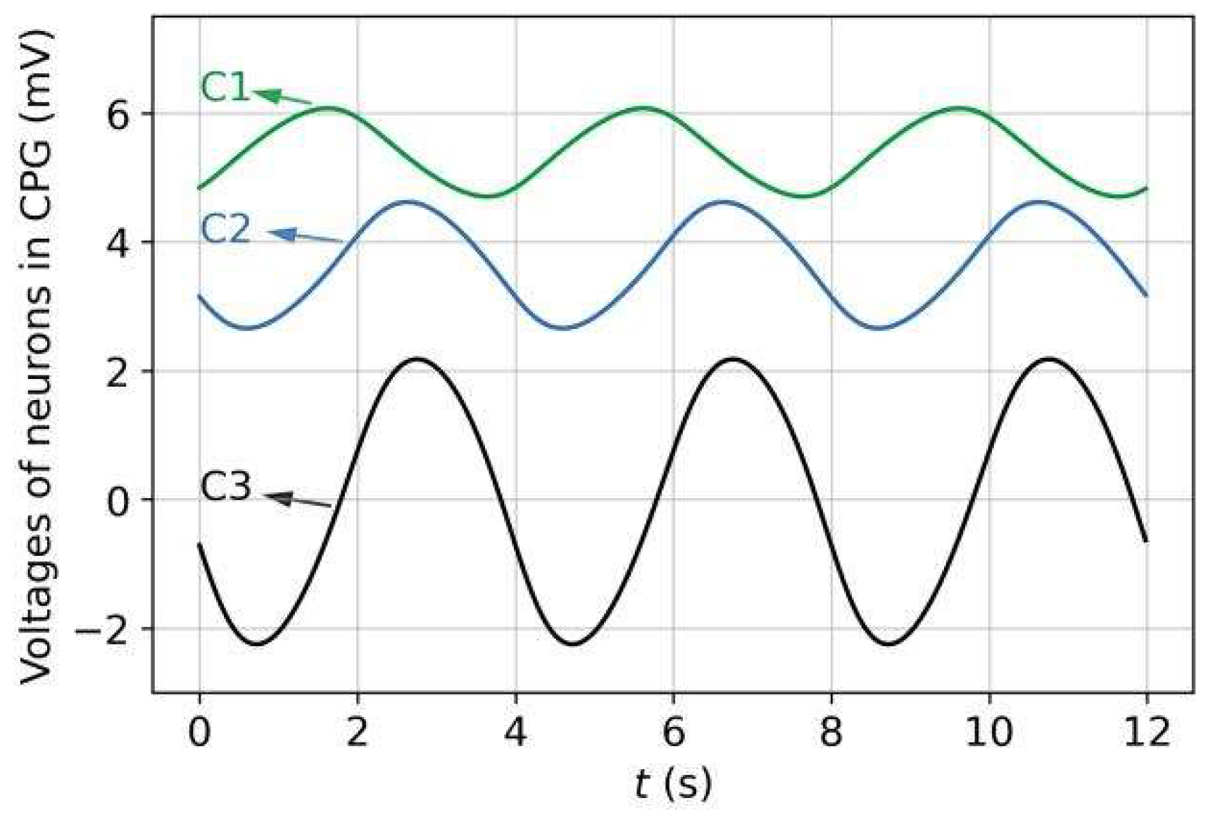
3.1. Rhythmic Patterns of CPG and Joint Angles

Figure 7 shows the voltage dynamics of the CPG neurons, obtained from our simulations. Through the neuron interactions, the C3 neuron, as the CPG output neuron, generated an approximate sinusoidal oscillatory voltage with a 4-s period and the same positive and negative amplitudes. In the absence of sensory input, the oscillatory voltage of C3 (processed and transmitted by the head network circuit) caused the Joint-1 angle to vary periodically, being centered at zero with the same period, as shown in Figure 8a. Figure 8b shows the changes in all joint angles over time. All joint angles exhibited the same rhythmic oscillation pattern, but the oscillation of each joint (except Joint 1) had a time lag of approximately T o s c / 10 compared with that of its anterior adjacent joint. Through backward propagation, the oscillation of the Joint-11 angle was almost synchronized with that of Joint 1.

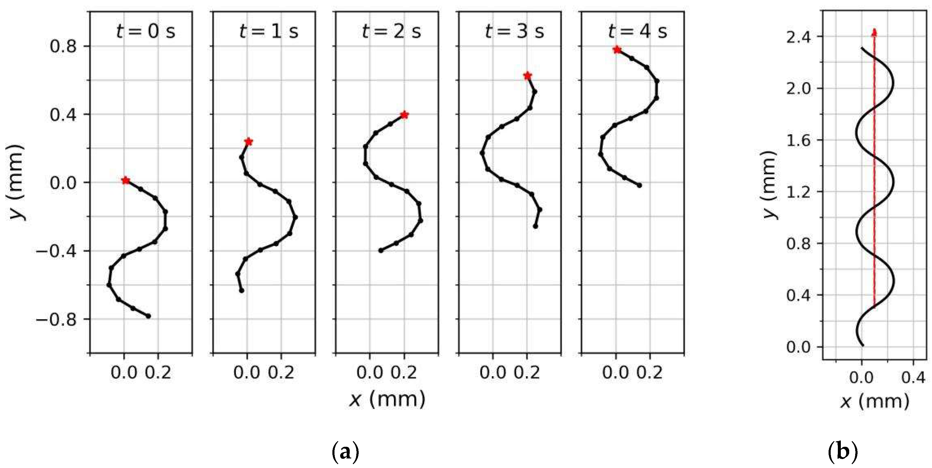
3.2. Forward Undulatory Locomotion Behavior of Model

We observed the behavior of the model under the rhythmic pattern shown in Figure 8. Figure 9a shows the positions and shapes of the rigid link system at 1-s intervals during the first period. We initialized the t = 0 s position as ( 0 , 0 ) and φ1(0) = 150°. In terms of spatial mode, θ1(0) = 0° and the joint angles from front to back increased, decreased, and increased again, thereby shaping the link system as a sinusoidal wave, similar to the real-world behavior of C. elegans. As time progressed, Joint 1 rotated periodically and the model moved forward in a fluctuating pattern, forming a sinusoidal trajectory. The posterior joints and, hence, the shape of the link system, varied accordingly. For example, the model was transformed from the left sweep at t = 0 s to the right sweep at t = 1 s and 2 s. After one period (at t = 4 s), the trajectory drew a sine curve with a complete period and the system shape returned to that at t = 0 s. The system wavelength during locomotion was approximately 0.83 times the system length (measurements of real C. elegans on agar fall in the range of 0.4 to 0.9 [43]). Additionally, from the trajectory in Figure 9b, the model traveled straight with an undulating pattern in the absence of sensory input, because the positive and negative swing amplitudes of θ1 were consistent (Figure 8a).

3.3. Adaptive Responses of Sensory Neuron Models

ASEL was selected as an example to verify whether the responses of the sensory neuron model met the desired characteristics given in Section 2.4.1. As shown in Figure 4a, a concentration up step evoked ASEL depolarization, and its voltage trace exhibited a rapid increase and subsequent slow decay. According to the design of sensory neuron models, the ASEL response amplitude is influenced by the concentration difference ΔC(t) and historical average absolute concentration difference CN(t) (refer to Equations (19) and (20)). Figure 10 shows the ASEL response voltage peak as a function of ΔC(t) and CN(t), from which the following observations can be drawn:
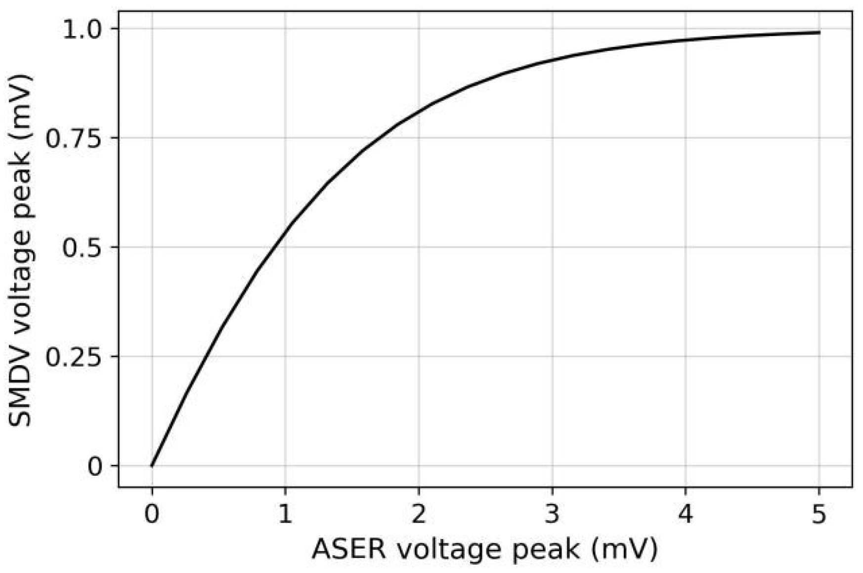
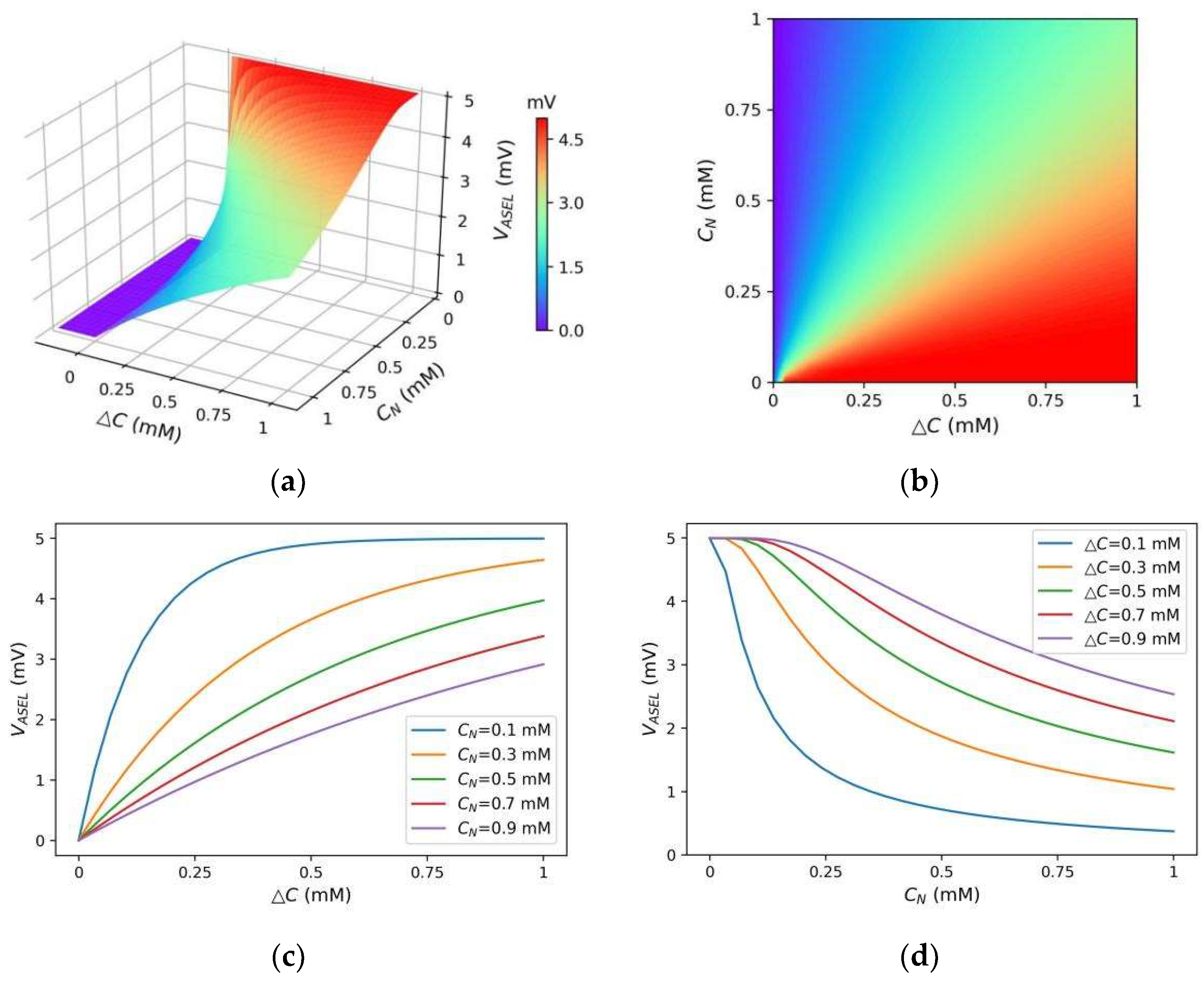
  • ASEL responded to concentration increases (ΔC(t) > 0) only, as required in S1;
  • When positive ΔC(t) was small, the ASEL response amplitude was small. The ASEL voltage peak increased with the increase in ΔC(t) for any given CN(t) (Figure 10b,c). This indicates that for the local scenario or the scenario with small gradient differences (i.e., the model did not need to re-adapt to the new gradient range), the ASEL response amplitude was proportional to the detected temporal gradient, as required in S2. On this basis, the model can control the steering amplitude by comparing magnitudes of the same-polarity gradients;
  • When CN(t) was small, the ASEL response amplitude was large, implying that ASEL was highly sensitive to the gradient. The ASEL voltage peak decreased with the increase in CN(t) for any positive ΔC(t) (Figure 10b,d). This indicates that the ASEL response was adaptive to the local environment. When exposed to large concentration gradients for a period, the sensory neurons became less sensitive to the gradients. Thus, the characteristic in S3 was satisfied, allowing the model to operate effectively across a wide range of gradients.
In conclusion, the response dynamics of ASEL satisfied the desired characteristics. Similar characteristics were observed for ASER, except that the sensory neuron responded to concentration decreases as designed; these results are not reported here.
The responses of sensory neurons reflect only the temporal gradients scaled by CN(t). Klinokinesis-related steering depends solely on the scaled temporal gradient, according to the ASER response. Meanwhile, klinotaxis-related steering depends on the normal gradient, i.e., gradients in the normal direction (Figure 2), according to the ASEL and ASER responses. This is achieved via the state-dependent gating mechanism, that is, the klinotaxis control circuit combines the network internal state with the sensory neuron responses to implicitly extract the normal gradient information corresponding to the current locomotion phase (see Section 2.4.2 for details).

3.4. Autonomous Search Behavior of Model

To verify that the proposed model can search for a concentration peak in a direction close to the steepest gradient, we performed simulations with concentrations having Gaussian distributions.
First, we observed the model trajectories in a scenario where the concentration peak position was (0, 0) and the maximum concentration was 50 mM. The model began moving from different initial positions and with different initial orientations. For comparison, we eliminated one strategy (klinokinesis or klinotaxis) from the proposed model, and the same experiments were also performed for models utilizing a single strategy. The navigation method of the model with klinotaxis eliminated is similar to that of the previous models [29]. Figure 11 shows several trajectories for the three models (two parallel strategies, klinokinesis only, and klinotaxis only) obtained for the same initial conditions. Comparison of these trajectories yielded the following observations:
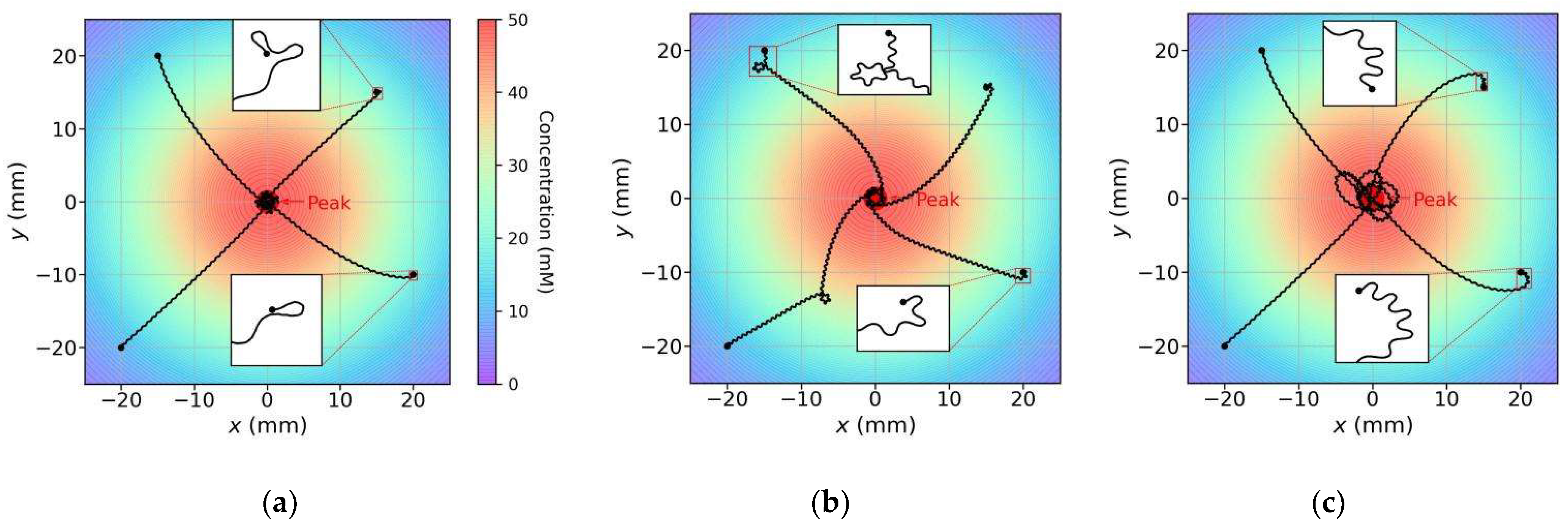
  • For various initial conditions, the three models moved forward in a sinusoidal fashion and successfully reached the concentration peak; however, their search trajectories varied;
  • As regards the search trajectories of the klinokinesis-only model (Figure 11b), for the positive gradient direction, the model did not steer, even if there was a deviation from the peak direction. The model corrected the locomotion direction by right turns only when negative gradients were encountered; this behavior is consistent with that of the previous models [29]. In other words, the model could only ensure that it was moving close to the peak, but not that it was using a short search path. In such cases, a large locomotion undulation is advantageous, because a large swing facilitates detection of a negative gradient and adjustment to a more favorable direction. However, a large swing also yields a longer path and may increase the search time;
  • As regards the search trajectories of the klinotaxis-only model (Figure 11c), this model continuously and gradually veered toward the side with higher concentration throughout the undulatory locomotion. The orientation adjustment of the model was slightly slower than that of the klinokinesis-only model for negative gradients (compare the beginnings of trajectories whose beginning position are (20, −10) in Figure 11b,c). Because the ASEL responses reduced the Joint-1 oscillation amplitude when the model moved toward positive gradients, the model swing amplitude decreased; hence, the search paths were shortened;
  • Our model, which integrates both strategies, yielded significantly shortened search paths (Figure 11a). Regardless of the initial position and orientation, the model reached a peak in a direction close to the steepest gradient. If the search began in a direction away from the peak, the klinokinesis strategy allowed the model to make sharp turns to rapidly correct the direction. Meanwhile, the klinotaxis strategy allowed the model to gradually optimize the locomotion direction according to the deviation between the instantaneous and peak directions.
Two metrics were used to measure the model search performance: the arrival rate and SSR. The arrival rate is the ratio of the number of times the model reached the concentration peak to the total number of experiments, where the peak point is defined as a circular area within 1 mm of the maximum concentration point in the simulations. The SSR is the ratio of the model search time to reach the concentration peak to that corresponding to the shortest path (i.e., the linear distance from the initial position to the concentration peak position).
We then tested the three models in 10 scenarios with different gradient ranges. The maximum concentration for each scenario varied from 50 to 1400 mM. In each scenario, the models began moving from four different initial positions with 10 different initial orientations; that is, each model was run 40 times per scenario for a total of 400 times across all scenarios. Figure 12 shows the average search performance results obtained for the three models in each scenario, and Table 1 lists the average results for the models across all experiments. The following conclusions were drawn:
  • The arrival rates of all three models were 1, indicating that the models reached the concentration peaks in all experiments regardless of whether they used single or parallel strategies. In addition, the standard deviations of the SSRs for all models were very small, indicating that the models had robust search performance for different scenarios and initial conditions;
  • Compared with the models using a single strategy, the average SSR of the model using parallel strategies was the smallest and close to 1, indicating that the search paths were effectively shortened by simultaneous use of the two complementary strategies, and that the search paths were approximated to the optimal paths although the model moved along a waveform path instead of a straight line;
  • The average SSR of the klinokinesis-only model was much larger; this was because it did not optimize the path in the direction of the positive gradients and the swing amplitude of the undulatory locomotion was large (see Figure 11b).
Additionally, to verify the role of dynamic adaptation in the sensory neuron models, we conducted the same experiments on a non-adaptive model. In that case, the sensory neuron models did not contain the normalization term with respect to CN(t). That is, the ASEL conductance activation term in Equation (19) was modified to g A S E L ( t ) = g max tanh ( a | Δ C ( t ) | )   , and the corresponding ASER term was similarly modified. The coefficient, a, took on three different values. Comparison of the results presented in Figure 12 and Table 1 reveals that the non-adaptive models had comparable search performance to that of the adaptive model within a narrow gradient range, and that the search performance deteriorated seriously beyond this range. For small a in particular, the response amplitudes of the sensory neurons in the small-gradient scenario were too small, which may have caused a model search failure (i.e., the arrival rate was not 1). In contrast, the adaptive sensory neuron models could dynamically adjust their response sensitivities to the gradient according to the gradient amplitude in the preceding time period, so that the model maintained stable search performance in all scenarios.

3.5. Analysis of Search Behavior

The shape of the rigid link system during the steering induced by the navigation behavior was observed. Figure 13 shows shapes at five different stages as the model underwent an Ω turn (a sharp turn performed by C. elegans). When the head turned, the rigid link system bent accordingly (i.e., at times t2, t3, and t4). The link system shape at each stage was close to the corresponding trajectory shape. After the head returned to a normal swing, the entire link system returned to the normal sinusoidal undulation (i.e., at time t5). This suggests that the rigid link system could be shaped similarly to the body of a real worm during steering.
Additionally, to verify that the navigation decisions generated by the model conformed to the two chemotaxis strategies of C. elegans, we performed a quantitative analysis of all trajectories of the models using klinokinesis only and klinotaxis only. First, we calculated and statistically analyzed the relationship between the turning biases and normal concentration gradients in the klinotaxis-only trajectories; the result are shown in Figure 14a. The average turning bias was positively correlated with the normal gradient, which is consistent with the statistical results of biological experiments [3]. This suggests that the proposed model mimicked the klinotaxis behavior of real-world C. elegans, steering to the side with the higher concentration. We then calculated the relationship between the turning bias and the temporal gradient of the concentration in the klinokinesis-only trajectories, as shown in Figure 14b. For positive gradients, the turning bias was almost zero. For negative gradients, the turning bias was negative (i.e., the model turned right) and the amplitude was proportional to the gradient amplitude. These results have the same trend as biological results [3,4]. In addition, comparing Figure 14a,b, the steering amplitude obtained for the klinokinesis behavior was greater than that for the klinotaxis behavior; this is also consistent with biological findings [3].

3.6. Discussion

This section highlights the differences and advantages of our study compared with previous related research. Most existing navigation models inspired by C. elegans chemotaxis aim to realize the chemotaxis behavior and, on this premise, explore the underlying mechanisms from the biological perspective; therefore, less attention is paid on the search performance of models from an engineering perspective. In contrast, the purpose of this study is to replicate the complete chemotaxis behavior of C. elegans, including parallel chemotaxis strategies and body movement, in the context of one sensor, and to provide an easy-to-implement and good-performance model for worm-like robot navigation control. Table 2 lists the capabilities and properties of related navigation models in the literature and those of the proposed model, which are summarized as follows:
(1)
Previous models typically adopted one strategy to perform navigation tasks. In contrast, our model combines two strategies to improve the search performance;
(2)
Our model can realize the klinotaxis behavior with a single sensor by incorporating the state-dependent gating mechanism, whereas previous models that mimic klinotaxis typically require two sensors to obtain the required spatial gradient;
(3)
Our model can realize body undulatory locomotion during steering by incorporating a proprioceptive mechanism, similar to the model in [29]. However, the structure of our model is simpler;
(4)
Our model exhibits adaptive sensitivity to the concentration gradient to cope with scenarios with various gradient ranges, a function which is absent in the previous models.
Additionally, in simulations, the proposed model exhibited realistic undulatory locomotion and a stable search for the shortest-path concentration peak over a wide range of gradients. Moreover, the simulation results have demonstrated that the search performance of our model combining two strategies is significantly better than that of models using a single strategy.
For further comparison, we conducted a comparative experiment between our model and the model in [29]; this model also uses a single sensor and incorporates undulatory locomotion of the body, and the implementation approach of klinokinesis in our model is similar to that of this model. We reproduced the model in [29] using the original logic function and parameters. We tested our model against this model according to the scenario used in [29]; the peak concentration and diffusion range in this scenario are very small. Figure 15a,b show the search trajectories of our model and the model from [29], respectively. The trajectory patterns were consistent with those shown in Figure 11a,b, respectively. Multiple experiments were conducted with four different initial positions and 10 different initial orientations; the average SSRs were 1.961 for the reproduced model and 1.486 for our model. The ratio of average SSR of the reproduced model to that of our model was 1.32, which was close to the results in Section 3.4; as shown in Table 1, the ratio of average SSR of the klinokinesis-only model to that of our model was 1.36. In addition, the reproduced model needed to normalize the concentration gradient in the scenario in advance, while, in practice, it is difficult to obtain a priori knowledge of the gradient range of an unknown scenario.

4. Conclusions

To incorporate new biological methods into mobile-robot control, a neural network-based autonomous search model with undulatory locomotion inspired by C. elegans was proposed in this study. The developed model is the first to simultaneously mimic the body locomotion and the klinokinesis and klinotaxis strategies of C. elegans with a single sensor, to search for environmental variable peaks in directions close to the steepest gradients. Multiple biological outcomes are incorporated into the model so that the simple structure is sufficient to achieve complex C. elegans-like behavior. Specifically, the CPG and proprioceptive mechanism of C. elegans are incorporated in the model to achieve undulatory locomotion, as well as the electrophysiological characteristics of salt-sensory neurons and the state-dependent gating mechanism; the latter is included to achieve klinotaxis behavior in the case of a single sensor. In addition, klinokinesis behavior is realized by fitting a logic function. In this study, the effectiveness and realness of the proposed model were demonstrated through simulation experiments. The model exhibited stable search performance across a wide range of gradients and outperformed models using a single strategy, while exhibiting realistic body undulation.
In summary, the developed model constitutes a simple bio-inspired network control prototype for worm-like navigation robots. In future work, extending the model by including more navigation strategies will contribute to addressing possible problems in complex scenarios, such as lack of gradient or local extremum. Additionally, the developed model will be considered for application in actual robots.

Author Contributions

Conceptualization, M.C. and D.F.; methodology, M.C., D.F. and H.S.; software, M.C.; validation, M.C., M.W. and T.S.; resources, D.F. and H.S.; writing—original draft preparation, M.C.; writing—review and editing, M.C., M.W. and T.S.; supervision, D.F. and H.S. All authors have read and agreed to the published version of the manuscript.

Funding

This research was funded by the National Natural Science Foundation of China [grant number 61971470].

Institutional Review Board Statement

Not applicable.

Informed Consent Statement

Not applicable.

Data Availability Statement

Not applicable.

Conflicts of Interest

The authors declare no conflict of interest. The funders had no role in the design of the study; in the collection, analyses, or interpretation of data; in the writing of the manuscript; or in the decision to publish the results.

References

  1. White, J.G.; Southgate, E.; Tomson, J.N.; Brenner, S. The structure of the nervous system of the nematode Caenorhabditis elegans. Philos. Trans. R. Soc. Lond. B Biol. Sci. 1986, 314, 1–340. [Google Scholar] [PubMed]
  2. Cook, S.J.; Jarrell, T.A.; Brittin, C.A.; Wang, Y.; Bloniarz, A.E.; Yakovlev, M.A.; Nguyen, K.; Tang, L.T.; Bayer, E.A.; Duerr, J.S. Whole-animal connectomes of both Caenorhabditis elegans sexes. Nature 2019, 571, 63–71. [Google Scholar] [CrossRef] [PubMed]
  3. Iino, Y.; Yoshida, K. Parallel use of two behavioral mechanisms for chemotaxis in Caenorhabditis elegans. J. Neurosci. 2009, 29, 5370–5380. [Google Scholar] [CrossRef] [PubMed] [Green Version]
  4. Pierce-Shimomura, J.T.; Morse, T.M.; Lockery, S.R. The fundamental role of pirouettes in Caenorhabditis elegans chemotaxis. J. Neurosci. 1999, 19, 9557–9569. [Google Scholar] [CrossRef] [PubMed] [Green Version]
  5. Macedo, J.A.; Marques, L.; Costa, E. A comparative study of bio-inspired odour source localisation strategies from the state-actionperspective. Sensors 2019, 19, 2231. [Google Scholar] [CrossRef] [PubMed] [Green Version]
  6. Li, J.-G.; Cao, M.-L.; Meng, Q.-H. Chemical source searching by controlling a wheeled mobile robot to follow an online planned route in outdoor field environments. Sensors 2019, 19, 426. [Google Scholar] [CrossRef] [Green Version]
  7. Huo, J.; Liu, M.; Neusypin, K.A.; Liu, H.; Guo, M.; Xiao, Y. Autonomous search of radioactive sources through mobile robots. Sensors 2020, 20, 3461. [Google Scholar] [CrossRef]
  8. Bayat, B.; Crasta, N.; Crespi, A.; Pascoal, A.M.; Ijspeert, A. Environmental monitoring using autonomous vehicles: A survey of recent searching techniques. Curr. Opin. Biotech. 2017, 45, 76–84. [Google Scholar] [CrossRef] [Green Version]
  9. Webster, R.J.; Romano, J.M.; Cowan, N.J. Mechanics of precurved-tube continuum robots. IEEE Trans. Robot. 2009, 25, 67–78. [Google Scholar] [CrossRef]
  10. Iguchi, Y.; Nakajima, M.; Ariizumi, R.; Tanaka, M. Step climbing control of snake robot with prismatic joints. Sensors 2022, 22, 4920. [Google Scholar] [CrossRef]
  11. Zhao, X.; Dou, L.; Su, Z.; Liu, N. Study of the navigation method for a snake robot based on the kinematics model with MEMS IMU. Sensors 2018, 18, 879. [Google Scholar] [CrossRef] [PubMed] [Green Version]
  12. Gray, J.M.; Hill, J.J.; Bargmann, C.I. Inaugural Article: A circuit for navigation in Caenorhabditis elegans. Proc. Natl. Acad. Sci. USA 2005, 102, 3184–3191. [Google Scholar] [CrossRef] [PubMed] [Green Version]
  13. Chalfie, M.; Sulston, J.E.; White, J.G.; Southgate, E.; Thomson, J.N.; Brenner, S. The neural circuit for touch sensitivity in Caenorhabditis elegans. J. Neurosci. 1985, 5, 956–964. [Google Scholar] [CrossRef] [PubMed] [Green Version]
  14. Bargmann, C.I.; Horvitz, H.R. Chemosensory neurons with overlapping functions direct chemotaxis to multiple chemicals in C. elegans. Neuron 1991, 7, 729–742. [Google Scholar] [CrossRef]
  15. Wen, Q.; Po, M.D.; Hulme, E.; Chen, S.; Liu, X.; Kwok, S.W.; Gershow, M.; Leifer, A.M.; Butler, V.; Fang-Yen, C. Proprioceptive coupling within motor neurons drives C. elegans forward locomotion. Neuron 2012, 76, 750–761. [Google Scholar] [CrossRef] [Green Version]
  16. Fouad, A.D.; Teng, S.; Mark, J.R.; Liu, A.; Alvarez-Illera, P.; Ji, H.; Du, A.; Bhirgoo, P.D.; Cornblath, E.; Guan, S.A. Distributed rhythm generators underlie Caenorhabditis elegans forward locomotion. eLife 2018, 7, e29913. [Google Scholar] [CrossRef]
  17. Chen, M.; Feng, D.; Su, H.; Su, T.; Wang, M. Neural model generating klinotaxis behavior accompanied by a random walk based on C. elegans connectome. Sci. Rep. 2022, 12, 3043. [Google Scholar] [CrossRef]
  18. Yu, Y.V.; Xue, W.; Chen, Y. Multisensory integration in Caenorhabditis elegans in comparison to mammals. Brain Sci. 2022, 12, 1368. [Google Scholar] [CrossRef]
  19. Ferrée, T.C.; Marcotte, B.A.; Lockery, S.R. Neural network models of chemotaxis in the nematode Caenorhabditis elegans. Adv. Neural Inf. Process. Syst. 1996, 9, 55–61. [Google Scholar]
  20. Ferrée, T.C.; Lockery, S.R. Computational rules for chemotaxis in the nematode C. elegans. J. Comput. Neurosci. 1999, 6, 263–277. [Google Scholar] [CrossRef]
  21. Dunn, N.A.; Lockery, S.R.; Pierce-Shimomura, J.T.; Conery, J.S. A neural network model of chemotaxis predicts functions of synaptic connections in the nematode Caenorhabditis elegans. J. Comput. Neurosci. 2004, 17, 137–147. [Google Scholar] [CrossRef] [PubMed]
  22. Morse, T.M.; Ferree, T.C.; Lockery, S.R. Robust spatial navigation in a robot inspired by chemotaxis in Caenorhabditis elegans. Adapt Behav. 1998, 6, 393–410. [Google Scholar] [CrossRef]
  23. Xu, J.X.; Deng, X.; Ji, D. Biological neural network based chemotaxis behaviors modeling of C. elegans. In Proceedings of the International Joint Conference on Neural Networks, Barcelona, Spain, 18–23 July 2010; pp. 1–6. [Google Scholar]
  24. Xu, J.X.; Deng, X. Biological modeling of complex chemotaxis behaviors for C. elegans under speed regulation—A dynamic neural networks approach. J. Comput. Neurosci. 2013, 35, 19–37. [Google Scholar] [CrossRef] [PubMed]
  25. Santurkar, S.; Rajendran, B. C. elegans chemotaxis inspired neuromorphic circuit for contour tracking and obstacle avoidance. In Proceedings of the IEEE International Joint Conference on Neural Networks, Killarney, Ireland, 12–17 July 2015; pp. 1–8. [Google Scholar]
  26. Shukla, S.; Dutta, S.; Ganguly, U. Design of spiking rate coded logic gates for C. elegans inspired contour tracking. In Proceedings of the 27th International Conference on Artificial Neural Networks, Rhodes, Greece, 4–7 October 2018; pp. 273–283. [Google Scholar]
  27. Kishore, A.; Saraswat, V.; Ganguly, U. Simplified klinokinesis using spiking neural networks for resource-constrained navigation on the neuromorphic processor Loihi. In Proceedings of the International Joint Conference on Neural Networks, Shenzhen, China, 18–22 July 2021; pp. 1–8. [Google Scholar]
  28. Deng, X.; Xu, J.X. A 3D undulatory locomotion model inspired by C. elegans through DNN approach. Neurocomputing 2014, 131, 248–264. [Google Scholar] [CrossRef]
  29. Deng, X.; Xu, J.X.; Wang, J.; Wang, G.; Chen, Q. Biological modeling the undulatory locomotion of C. elegans using dynamic neural network approach. Neurocomputing 2016, 186, 207–217. [Google Scholar] [CrossRef]
  30. Krieg, M.; Pidde, A.; Das, R. Mechanosensitive body-brain interactions in Caenorhabditis elegans. Curr. Opin. Neurobiol. 2022, 75, 102574. [Google Scholar] [CrossRef]
  31. Demin, A.V.; Vityaev, E.E. Learning in a virtual model of the C. elegans nematode for locomotion and chemotaxis. Biol. Inspired Cogn. Archit. 2014, 7, 9–14. [Google Scholar] [CrossRef]
  32. Costalago-Meruelo, A.; Machado, P.; Appiah, K.; Mujika, A.; Leskovsky, P.; Alvarez, R.; Epelde, G.; McGinnity, T.M. Emulation of chemical stimulus triggered head movement in the C. elegans nematode. Neurocomputing 2018, 290, 60–73. [Google Scholar] [CrossRef] [Green Version]
  33. Suzuki, H.; Thiele, T.R.; Faumont, S.; Ezcurra, M.; Lockery, S.R.; Schafer, W.R. Functional asymmetry in Caenorhabditis elegans taste neurons and its computational role in chemotaxis. Nature 2008, 454, 114–117. [Google Scholar] [CrossRef] [Green Version]
  34. Izquierdo, E.J.; Lockery, S.R. Evolution and analysis of minimal neural circuits for klinotaxis in Caenorhabditis elegans. J. Neurosci. 2010, 30, 12908–12917. [Google Scholar] [CrossRef] [Green Version]
  35. Izquierdo, E.J.; Beer, R.D. Connecting a connectome to behavior: An ensemble of neuroanatomical models of C. elegans klinotaxis. PLoS Comput. Biol. 2013, 9, e1002890. [Google Scholar] [CrossRef] [PubMed]
  36. Niebur, E.; Erdös, P. Theory of the locomotion of Nematodes: Dynamics of undulatory progression on a surface. Biophys. J. 1991, 60, 1132–1146. [Google Scholar] [CrossRef] [Green Version]
  37. Waterston, R. The Nematode C. elegans; Wood, W., Ed.; Cold Spring Harbor Laboratory Press: New York, NY, USA, 1988; pp. 281–335. [Google Scholar]
  38. Erdös, P.; Niebur, E. The neural basis of the locomotion of nematodes. Lect. Notes Phys. 1990, 368, 253–267. [Google Scholar]
  39. Xu, T.; Huo, J.; Shao, S.; Po, M.; Kawano, T.; Lu, Y.; Wu, M.; Zhen, M.; Wen, Q. Descending pathway facilitates undulatory wave propagation in Caenorhabditis elegans through gap junctions. Proc. Natl. Acad. Sci. USA 2018, 115, E4493–E4502. [Google Scholar]
  40. Mikolajczyk, T.; Mikołajewska, E.; Al-Shuka, H.F.N.; Malinowski, T.; Kłodowski, A.; Pimenov, D.Y.; Paczkowski, T.; Hu, F.; Giasin, K.; Mikołajewski, D.; et al. Recent advances in bipedal walking robots: Review of gait, drive, sensors and control systems. Sensors 2022, 22, 4440. [Google Scholar] [CrossRef]
  41. Han, Q.; Cao, F.; Yi, P.; Li, T. Motion control of a gecko-like robot based on a central pattern generator. Sensors 2021, 21, 6045. [Google Scholar] [CrossRef]
  42. Back, T. Evolutionary Algorithm in Theory and Practice; Oxford University Press: New York, NY, USA, 1996; pp. 106–130. [Google Scholar]
  43. Olivares, E.; Izquierdo, E.J.; Beer, R. A neuromechanical model of multiple network rhythmic pattern generators for forward locomotion in C. elegans. Front. Comput. Neurosci. 2021, 15, 572339. [Google Scholar] [CrossRef]
  44. Maruyama, I.N. Receptor Guanylyl Cyclases in Sensory Processing. Front. Endocrinol. 2017, 7, 173. [Google Scholar]
Figure 1. Overall model architecture: (a) multi-joint rigid link system abstracted from Caenorhabditis elegans (C. elegans) structure; and (b) network circuit. The circles, hexagons, ovals, and rectangles represent sensory neurons, oscillatory neurons, motoneurons, and muscle cells, respectively. The blue and red lines represent excitatory and inhibitory neural connections, respectively, where the central pattern generator (CPG) connection polarities were determined through evolution and the rest were specifically designed. The black lines represent neuromuscular connections.
Sensors 22 08825 g001
Figure 2. Definitions of kinematics-related terms.
Sensors 22 08825 g002
Figure 3. Dynamics of SMBD/V motoneuron and D/VM0 muscle in the absence of sensory input. The solid-colored curves are the projections of three-dimensional (3D) curves onto each plane.
Sensors 22 08825 g003
Figure 4. Changes in sensory neuron voltages and muscle outputs (bottom) as well as steering responses (top) caused by application of an up (a); or down (b) steps at two different locomotion phases. Black, orange, and blue represent the cases where no sensory stimulus is applied and where the sensory stimulus is applied at phase points c and e, respectively.
Sensors 22 08825 g004
Figure 5. Cumulative differences in D/VM0 output induced by application of an up (a); or down (b) step at each locomotion phase, where phase points c and e, respectively, correspond to phases c and e in Figure 4. The black dashed lines represent the shape of the locomotion trajectory.
Sensors 22 08825 g005
Figure 6. Logic function for mimicking klinokinesis behavior.
Sensors 22 08825 g006
Figure 7. Voltage dynamics of CPG neurons.
Sensors 22 08825 g007
Figure 8. (a) periodic changes in Joint-1 angle; and (b) kymogram depicting changes in all joint angles over time.
Sensors 22 08825 g008
Figure 9. Model shapes in one cycle (a); and the forward locomotion trajectory (b); under the rhythmic pattern shown in Figure 8. The red line represents the translation direction.
Sensors 22 08825 g009
Figure 10. (a) ASEL voltage peak as function of concentration difference ΔC(t) and historical average absolute concentration difference CN(t); (b) top view of (a); (c) variation tendency of ASEL voltage peak with the change of ΔC(t); and (d) variation tendency of ASEL voltage peak with the change of CN(t).
Sensors 22 08825 g010
Figure 11. Search trajectories of three models in a given scenario: (a) the model exploiting parallel (klinokinesis and klinotaxis) strategies; (b) the klinokinesis-only model; and (c) the klinotaxis-only model. The four trajectories of each model have different initial positions and orientations, and the initial conditions were the same for all models. The color of each position in the scenario represents the concentration of that position (marked by the color bar in (a)).
Sensors 22 08825 g011
Figure 12. Search performance of all models in scenarios with different concentration gradient ranges. Each point represents the average SSR for the model searches, where the model started from different initial positions and orientations.
Sensors 22 08825 g012
Figure 13. Shape of rigid link system during steering. The upper left diagram shows the model trajectory, and the shapes of the rigid link system at the position indicated by the five colored points are shown in the similarly colored sub-graphs. The pentagram represents the head tip (i.e., Node 1 of the system).
Sensors 22 08825 g013
Figure 14. Quantitative analysis of search behavior strategies: (a) turning bias vs. Normal concentration gradient of klinotaxis trajectories; and (b) turning bias vs. temporal gradient of klinokinesis trajectories. All gradients were linearly normalized to between −1 and 1.
Sensors 22 08825 g014
Figure 15. Search trajectories of our model (a); and the reproduced model (b) in the scenario used in [29].
Sensors 22 08825 g015
Table 1. Search performance results for different models across all experiments (±standard deviation).
StrategiesArrival RateAverage SSR
Klinokinesis only1.01.4922 ± 0.07309
Klinotaxis only1.01.1642 ± 0.09253
Parallel
(klinokinesis & klinotaxis)
Adaptive1.01.0964 ± 0.05162
Non-adaptive (a = 15)0.81.2474 ± 0.32701
Non-adaptive (a = 30)1.01.4388 ± 0.36184
Non-adaptive (a = 45)1.01.5720 ± 0.43820
Table 2. Comparison of capabilities and properties of models in the literature and in our study (Sensors 22 08825 i001 represents the presence of this capability or property in the model).
ArticlesCapabilitiesProperties
KlinokinesisKlinotaxisBody Undulatory LocomotionSingle SensorAdaptive Sensitivity to Gradients
Xu et al. [23,24]Model 1Sensors 22 08825 i001 Sensors 22 08825 i001
Model 2 Sensors 22 08825 i001
Santurkar et al. [25]Sensors 22 08825 i001 Sensors 22 08825 i001
Shukla et al. [26]Sensors 22 08825 i001 Sensors 22 08825 i001
Kishore et al. [27]Sensors 22 08825 i001 Sensors 22 08825 i001
Costalago-Meruelo et al. [32] Sensors 22 08825 i001Sensors 22 08825 i001
Deng et al. [28]Sensors 22 08825 i001 Sensors 22 08825 i001Sensors 22 08825 i001
Deng et al. [29]Sensors 22 08825 i001 Sensors 22 08825 i001Sensors 22 08825 i001
Our studySensors 22 08825 i001Sensors 22 08825 i001Sensors 22 08825 i001Sensors 22 08825 i001Sensors 22 08825 i001
Publisher’s Note: MDPI stays neutral with regard to jurisdictional claims in published maps and institutional affiliations.

