Figure 1.
RTK positioning procedures in a cell consisting of two follower UVs and a master UV. Two UVs perform the one-to-one RTK first, and the estimated baselines and resolved integer ambiguities are sent to a master that implements antenna array-aided RTK (A-RTK).
Figure 1.
RTK positioning procedures in a cell consisting of two follower UVs and a master UV. Two UVs perform the one-to-one RTK first, and the estimated baselines and resolved integer ambiguities are sent to a master that implements antenna array-aided RTK (A-RTK).
Figure 2.
RTK process among three cells realized by the one-to-one RTK or antenna array-aided RTK (A-RTK) between the masters in the cells. The baselines among the UVs across the cells are computed with a broadcast of resolved fixed-integer ambiguities.
Figure 2.
RTK process among three cells realized by the one-to-one RTK or antenna array-aided RTK (A-RTK) between the masters in the cells. The baselines among the UVs across the cells are computed with a broadcast of resolved fixed-integer ambiguities.
Figure 3.
There are three agents, wherein agent 1 and agent 2 have correctly resolved integer ambiguities. The rest of the integer ambiguities need to be resolved.
Figure 3.
There are three agents, wherein agent 1 and agent 2 have correctly resolved integer ambiguities. The rest of the integer ambiguities need to be resolved.
Figure 4.
Updated baselines and DD integer ambiguities after implementing an antenna array-aided RTK.
Figure 4.
Updated baselines and DD integer ambiguities after implementing an antenna array-aided RTK.
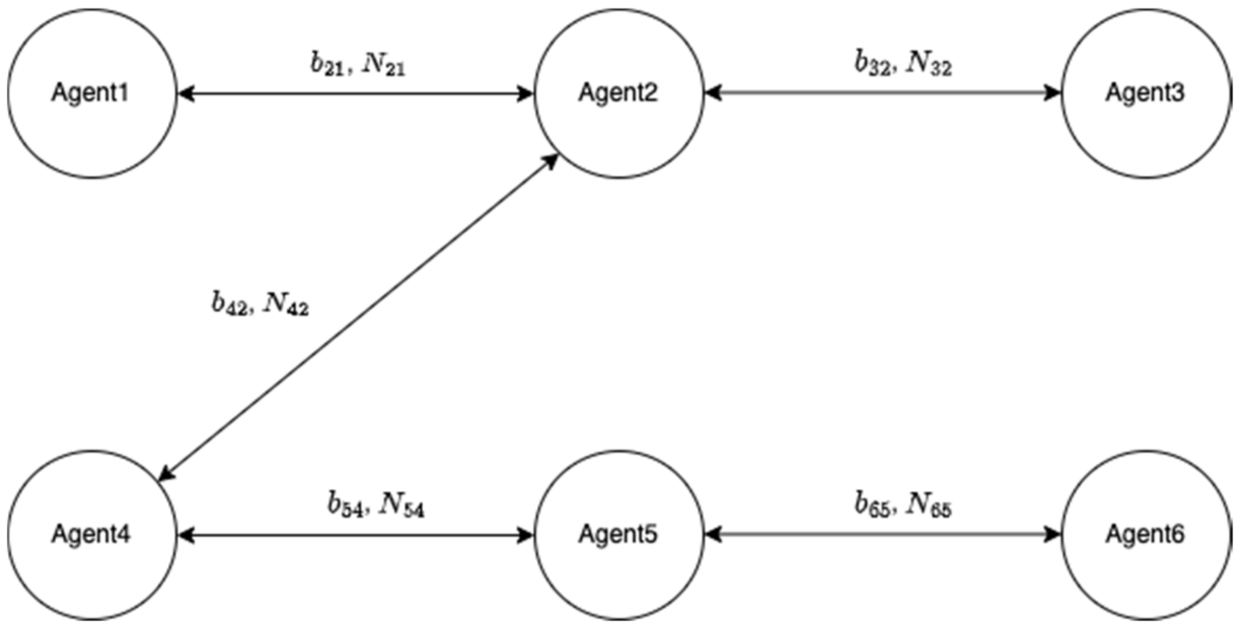
Figure 5.
There are six agents in a group of UVs wherein five baselines and DD integer ambiguities are assumed to be correctly determined.
Figure 5.
There are six agents in a group of UVs wherein five baselines and DD integer ambiguities are assumed to be correctly determined.
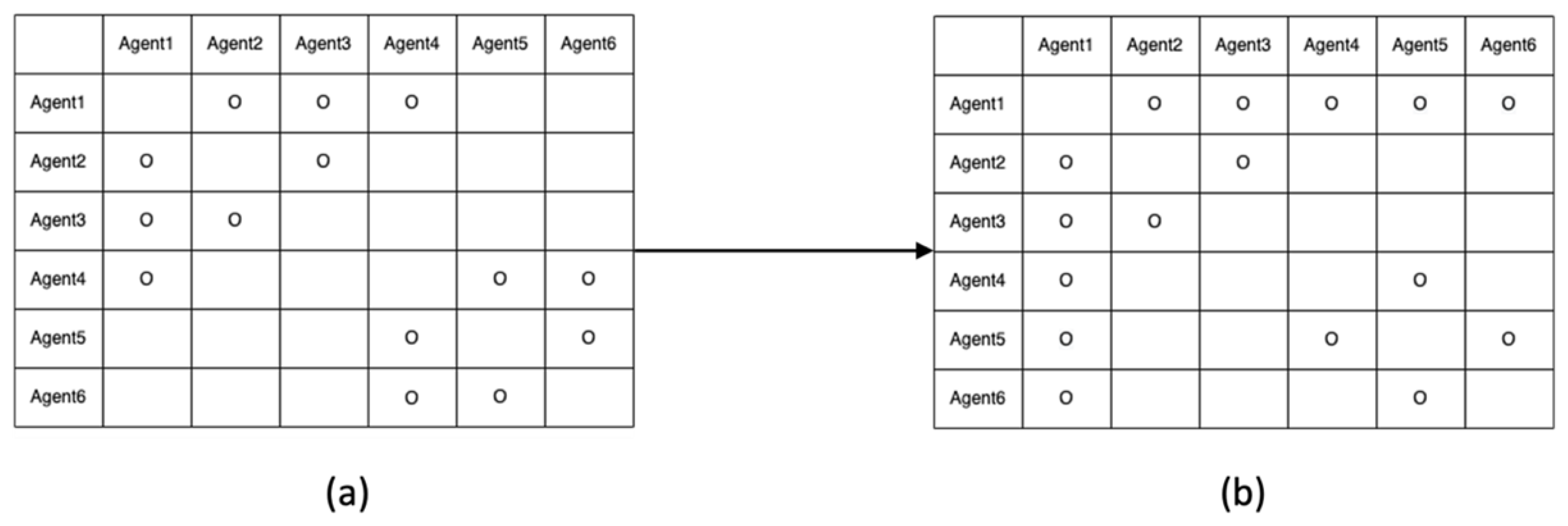
Figure 6.
Integer ambiguity resolution table for the six agents in
Figure 5.
Figure 6.
Integer ambiguity resolution table for the six agents in
Figure 5.
Figure 7.
Pseudocode for the integer ART process.
Figure 7.
Pseudocode for the integer ART process.
Figure 8.
ART processes while implementing the proposed pseudocode. (
a) Initial ART with resolved integer ambiguities in
Figure 5. (
b) Modified ART by updating
and
. (
c) Further modified ART by updating
. (
d) Further modified ART by updating
.
Figure 8.
ART processes while implementing the proposed pseudocode. (
a) Initial ART with resolved integer ambiguities in
Figure 5. (
b) Modified ART by updating
and
. (
c) Further modified ART by updating
. (
d) Further modified ART by updating
.
Figure 9.
Each cell consists of three agents. One of the agents in each cell is designated as a master agent which is responsible for communication to another cell.
Figure 9.
Each cell consists of three agents. One of the agents in each cell is designated as a master agent which is responsible for communication to another cell.
Figure 10.
ART table before applying a one-to-one or antenna array-aided RTK across the two cells.
Figure 10.
ART table before applying a one-to-one or antenna array-aided RTK across the two cells.
Figure 11.
ART table after implementing antenna array-aided RTK with agents 1, 4, and 5. (a) Modified ART after the one-to-one RTK between the two master agents. (b) Further modified ART by updating and .
Figure 11.
ART table after implementing antenna array-aided RTK with agents 1, 4, and 5. (a) Modified ART after the one-to-one RTK between the two master agents. (b) Further modified ART by updating and .
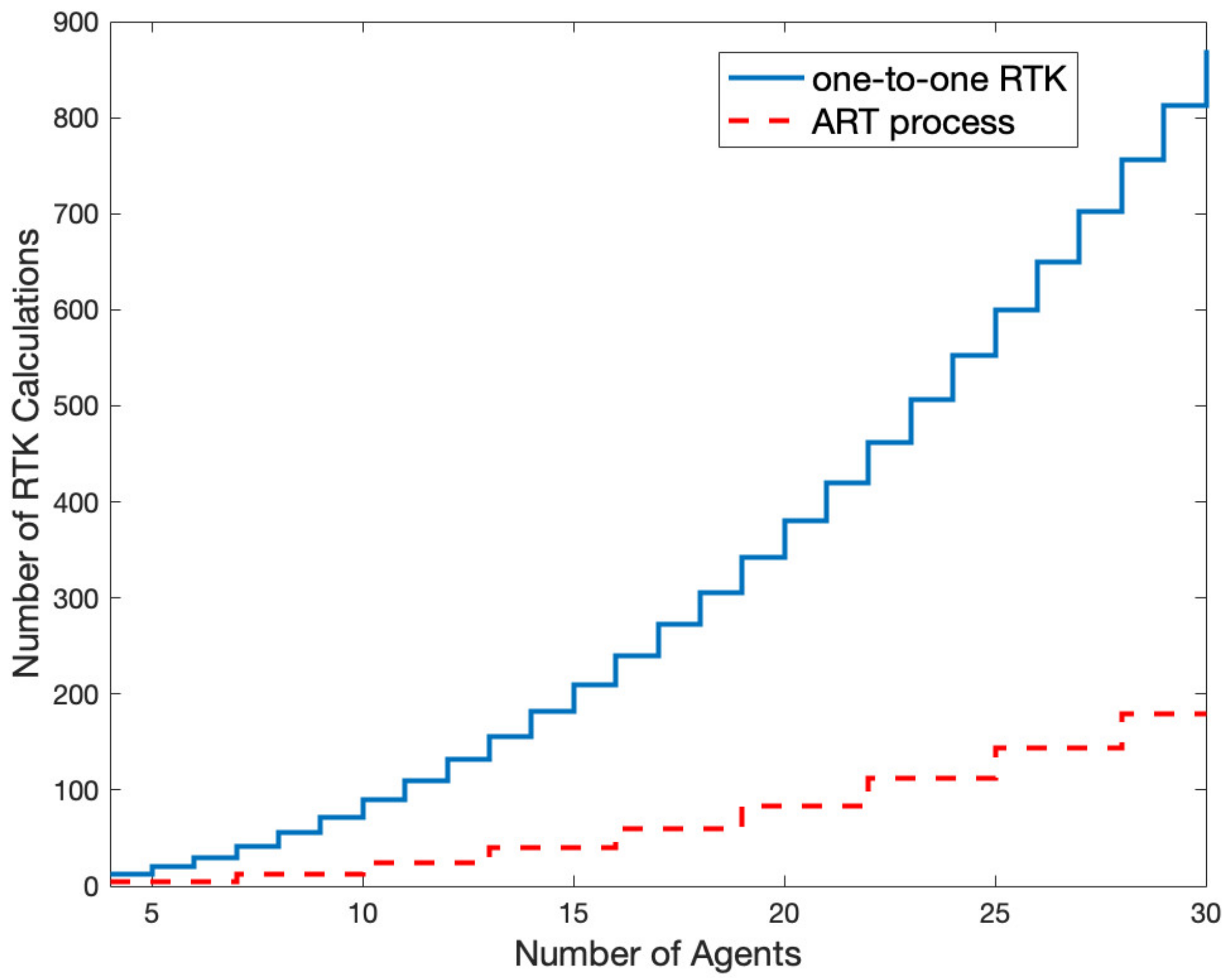
Figure 12.
Comparison of the number of computations between one-to-one RTK and ART process with respect to the number of agents.
Figure 12.
Comparison of the number of computations between one-to-one RTK and ART process with respect to the number of agents.
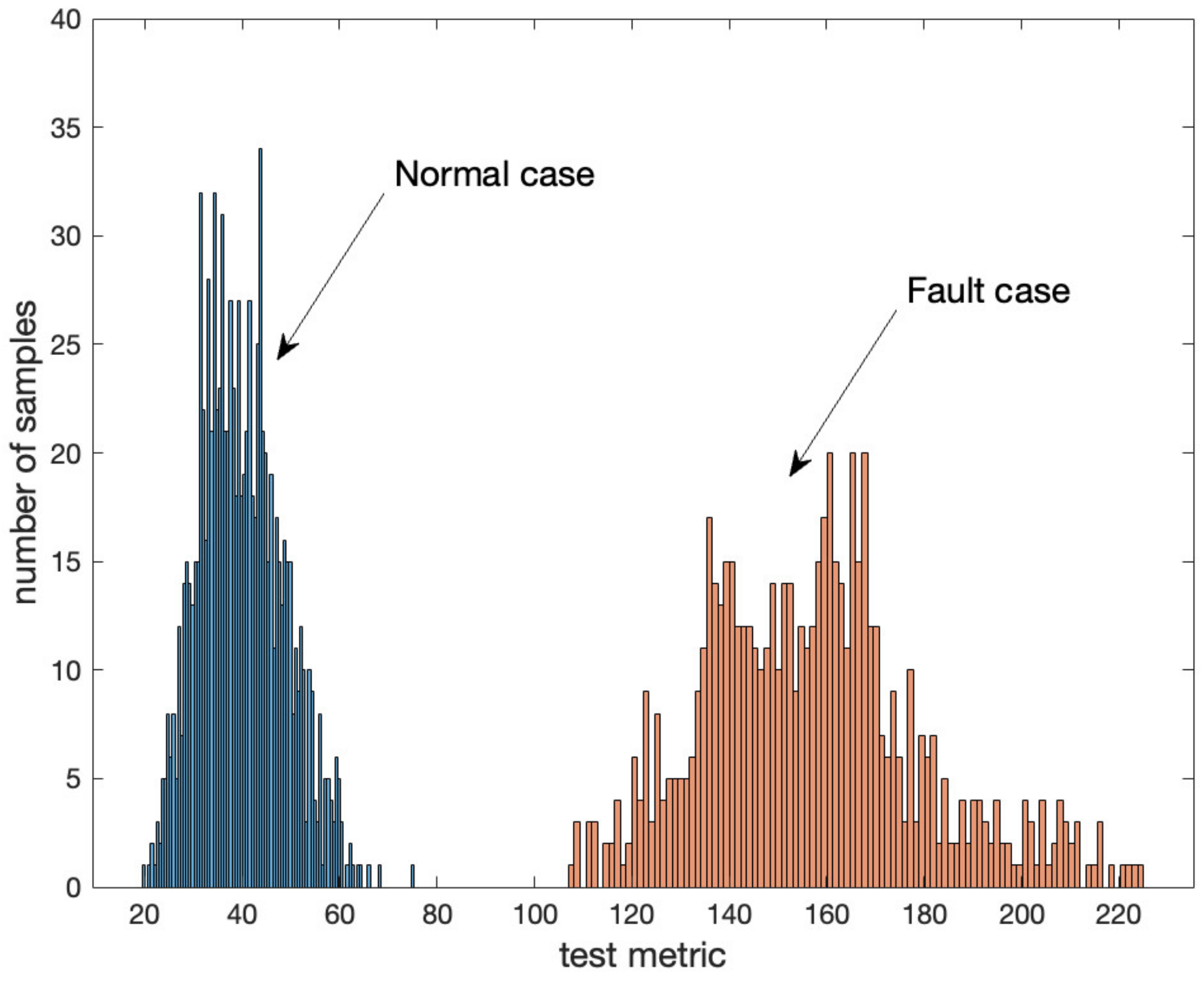
Figure 13.
Distributions of in normal and fault cases based on flight tests.
Figure 13.
Distributions of in normal and fault cases based on flight tests.
Figure 14.
Positioning errors of the broadcast baseline due to injected one cycle offset in one of DD integer ambiguities.
Figure 14.
Positioning errors of the broadcast baseline due to injected one cycle offset in one of DD integer ambiguities.
Figure 15.
Three quadrotors and GNSS receivers on ground during tests at Hongik University, Seoul, South Korea.
Figure 15.
Three quadrotors and GNSS receivers on ground during tests at Hongik University, Seoul, South Korea.
Figure 16.
Flight trajectories of agents 1,2, and 3 during the test.
Figure 16.
Flight trajectories of agents 1,2, and 3 during the test.
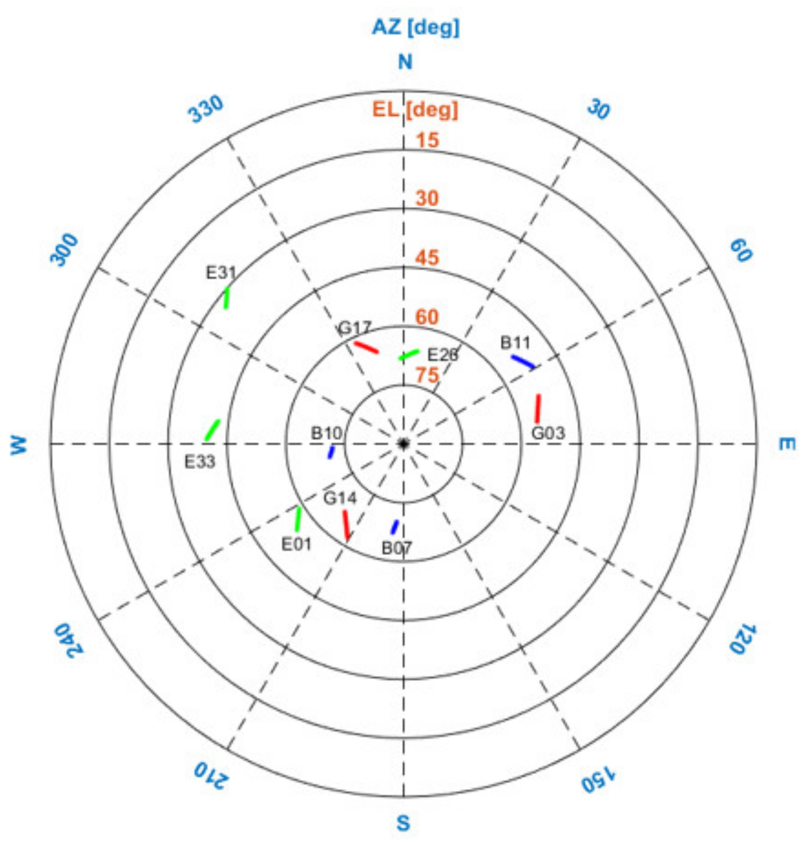
Figure 17.
Satellites commonly in view in the two cells during the flight test. GPS, Beidou, and Galileo satellites are indicated by the red, blue, and green lines, respectively.
Figure 17.
Satellites commonly in view in the two cells during the flight test. GPS, Beidou, and Galileo satellites are indicated by the red, blue, and green lines, respectively.
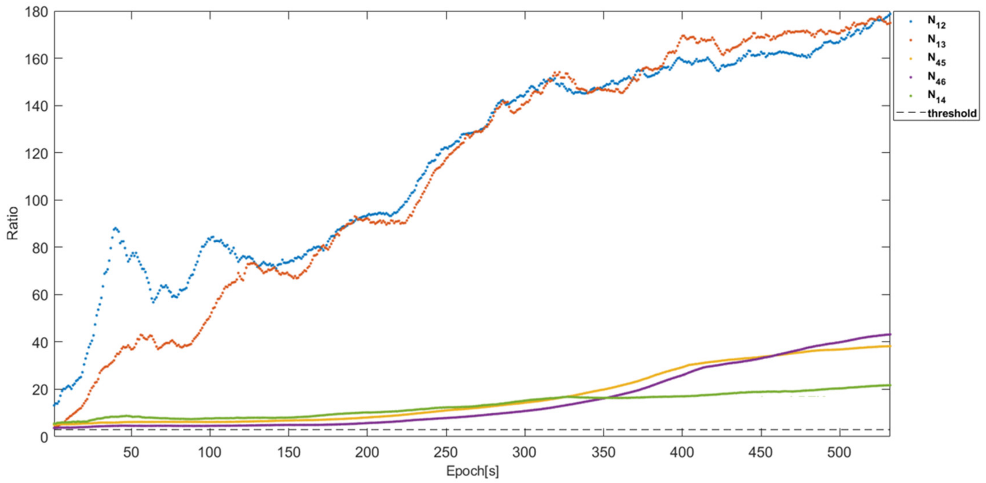
Figure 18.
The ratio test results of N12, N13, N43, N45, and N14. All ratios are greater than three from the first epoch.
Figure 18.
The ratio test results of N12, N13, N43, N45, and N14. All ratios are greater than three from the first epoch.
Figure 19.
Position errors of the baselines across the two cells using all satellites in view and the broadcast integer ambiguities based on the proposed framework.
Figure 19.
Position errors of the baselines across the two cells using all satellites in view and the broadcast integer ambiguities based on the proposed framework.
Figure 20.
The figure shows satellite IDs that each agent tracked. The two master agents had 10 common satellites and non-master agents had 6 common satellites in view. Each cell had 8 common satellites in view.
Figure 20.
The figure shows satellite IDs that each agent tracked. The two master agents had 10 common satellites and non-master agents had 6 common satellites in view. Each cell had 8 common satellites in view.
Figure 21.
Position errors of the baselines across the cells with the one-to-one RTK using 6 common satellites in view in
Figure 20.
Figure 21.
Position errors of the baselines across the cells with the one-to-one RTK using 6 common satellites in view in
Figure 20.
Figure 22.
Position errors of the baselines across the cells with the proposed framework using 6 common satellites in view in
Figure 20.
Figure 22.
Position errors of the baselines across the cells with the proposed framework using 6 common satellites in view in
Figure 20.
Table 1.
Proposed message fields and descriptions for the ART process.
Table 1.
Proposed message fields and descriptions for the ART process.
| Message ID | Messages | Description |
|---|
| 1 | Agent ID | Agent ID broadcasting messages |
| 2 | Other agent ID | A vector of agents having resolved integer ambiguities |
| 2 | GPS time of week | GPS time of week at the GNSS measurements |
| 3 | GNSS satellite PRN numbers | A vector of GNSS PRN number of the resolved integer ambiguities except for the pivot satellites |
| 4 | GNSS pivot satellite PRN numbers | A vector of a pivot satellite PRN number corresponding to Agent ID in Message ID 1. It is assumed that there is one pivot satellite per GNSS constellation |
| 5 | Fixed-integer ambiguities | A vector of fixed-integer ambiguities corresponding to Agent ID |
| 6 | Code phase measurements | A vector of received GNSS code phase measurements in the order of the pivot and other satellites in Message ID 4 |
| 7 | Carrier phase measurements | A vector of received GNSS carrier phase measurements in the order of the pivot and satellites in Message ID 4 |
| 8 | Fixed baseline | Estimated fixed baseline to other agents listed in Message ID 1 (this message is not used for a baseline computation but for a sanity check of the broadcast fixed-integer ambiguities) |
| 9 | Covariance matrix of fixed baseline | Covariance of the estimated fixed baseline of Message ID8 |
Table 2.
DD integer ambiguities within the two cells and between the two master agents using a one-to-one and antenna-array RTK of the proposed framework.
Table 2.
DD integer ambiguities within the two cells and between the two master agents using a one-to-one and antenna-array RTK of the proposed framework.
| Integer Index | Cell 1 | Cell 2 | Inter-Cells |
|---|
| N12 | N13 | N23 | N45 | N46 | N56 | N14 |
|---|
| 1
| −2 | −17 | −15 | −7 | −8 | −1 | −7 |
| 2
| 0 | 2 | 2 | 6 | 13 | 7 | −12 |
| 3
| −12 | −3 | 9 | 10 | 16 | 6 | −20 |
| 4
| 7 | 6 | −1 | 3 | −3 | −6 | 5 |
| 5
| −16 | −2 | 14 | 15 | 21 | 6 | −17 |
| 6
| −13 | −2 | 15 | 5 | 2 | −3 | −7 |
| 7
| −11 | −7 | 4 | 0 | 6 | 6 | −4 |
| 8
| −7 | −11 | −4 | −7 | −4 | 3 | −10 |
| 9
| 5 | 13 | 8 | −7 | −20 | −13 | −7 |
| 10
| −2 | 4 | 6 | 0 | 1 | 1 | −15 |
| 11
| −5 | −2 | 3 | −13 | −15 | −2 | 12 |
| 12
| −5 | 1 | 6 | −5 | 0 | 5 | 1 |
| 13
| −2 | −7 | −5 | −8 | −7 | 1 | 3 |
| 14
| −9 | −1 | 8 | −1 | 3 | 4 | 1 |
Table 3.
3D RMS positioning errors of the baselines in the two cells and two master agents using a one-to-one and antenna-array RTK of the proposed framework.
Table 3.
3D RMS positioning errors of the baselines in the two cells and two master agents using a one-to-one and antenna-array RTK of the proposed framework.
| | Cell 1 | Cell 2 | Inter-Cells |
|---|
| b12 | b13 | b23 | b45 | b46 | b56 | b14 |
|---|
| 3D RMS (cm) | 1.79 | 1.72 | 1.63 | 1.91 | 1.92 | 0.66 | 2.94 |
Table 4.
DD integer ambiguities across the two cells using the broadcast integer ambiguities of the proposed framework.
Table 4.
DD integer ambiguities across the two cells using the broadcast integer ambiguities of the proposed framework.
| | N15 | N16 | N24 | N25 | N26 | N34 | N35 | N36 |
|---|
| 1 | −20 | −28 | −5 | −18 | −26 | 10 | −3 | −11 |
| 2 | −18 | −25 | −12 | −18 | −25 | −14 | −20 | −27 |
| 3 | −10 | −4 | −8 | 2 | 8 | −17 | −7 | −1 |
| 4 | 8 | 2 | −2 | 1 | −5 | −1 | 2 | −4 |
| 5 | −2 | 4 | −1 | 14 | 20 | −15 | 0 | 6 |
| 6 | −2 | −5 | 6 | 11 | 8 | −9 | −4 | −7 |
| 7 | −4 | 2 | 7 | 7 | 13 | 3 | 3 | 9 |
| 8 | −10 | 6 | −3 | −3 | 13 | 1 | 1 | 17 |
| 9 | 0 | 13 | −12 | −5 | 8 | −20 | −13 | 0 |
| 10 | −15 | −14 | −13 | −13 | −12 | −19 | −19 | −18 |
| 11 | −1 | −3 | 17 | 4 | 2 | 14 | 1 | −1 |
| 12 | −4 | 1 | 6 | 1 | 6 | 0 | −5 | 0 |
| 13 | −5 | −4 | 5 | −3 | −2 | 10 | 2 | 3 |
| 14 | 0 | 4 | 10 | 9 | 13 | 2 | 1 | 5 |
Table 5.
The 3D RMS position errors of the baselines across the two cells using all satellites in view and the broadcast integer ambiguities of the proposed framework.
Table 5.
The 3D RMS position errors of the baselines across the two cells using all satellites in view and the broadcast integer ambiguities of the proposed framework.
| | b15 | b16 | b24 | b25 | b26 | b34 | b35 | b36 |
|---|
| 3D RMS (cm) | 5.04 | 3.69 | 2.88 | 4.75 | 3.43 | 2.72 | 4.60 | 3.25 |
Table 6.
DD integer ambiguity fix success probabilities and 3D RMS position errors of the baselines across the two cells using a one-to-one RTK with six common satellites in view in
Figure 20.
Table 6.
DD integer ambiguity fix success probabilities and 3D RMS position errors of the baselines across the two cells using a one-to-one RTK with six common satellites in view in
Figure 20.
| | b25 | b26 | b35 | b36 |
|---|
| Fixed 3D RMS (cm) | 5.15 | NA | 5.31 | NA |
| Overall 3D RMS (cm) | 169.57 | 332.60 | 158.62 | 303.80 |
| Ambiguity fix success probability (%) | 6.55 | 0 | 6.00 | 0 |
Table 7.
The 3D RMS positioning errors of the baselines in the two cells and two master agents using a one-to-one and antenna-array RTK of the proposed framework with the satellite configuration in
Figure 19.
Table 7.
The 3D RMS positioning errors of the baselines in the two cells and two master agents using a one-to-one and antenna-array RTK of the proposed framework with the satellite configuration in
Figure 19.
| | Cell 1 | Cell 2 | Inter-Cells |
|---|
| b12 | b13 | b23 | b45 | b46 | b56 | b14 |
|---|
| Fixed 3D RMS (cm) | 1.98 | 1.92 | 1.74 | 1.77 | 1.77 | 1.90 | 2.94 |
| Overall 3D RMS (cm) | 5.10 | N/A | 95.1 | 45.0 | N/A | 28.1 | 2.94 |
| Ambiguity fix success probability (%) | 99.8 | N/A | 83.1 | 96.1 | N/A | 98.7 | 100 |
Table 8.
3D RMS positioning errors of the baselines across the two cells with the proposed framework using 6 common satellites in view in
Figure 19.
Table 8.
3D RMS positioning errors of the baselines across the two cells with the proposed framework using 6 common satellites in view in
Figure 19.
| | b25 | b26 | b35 | b36 |
|---|
| 3D RMS (cm) | 5.29 | 3.23 | 5.12 | 3.06 |


