
On Power Line Positioning Systems


Abstract
1. Introduction
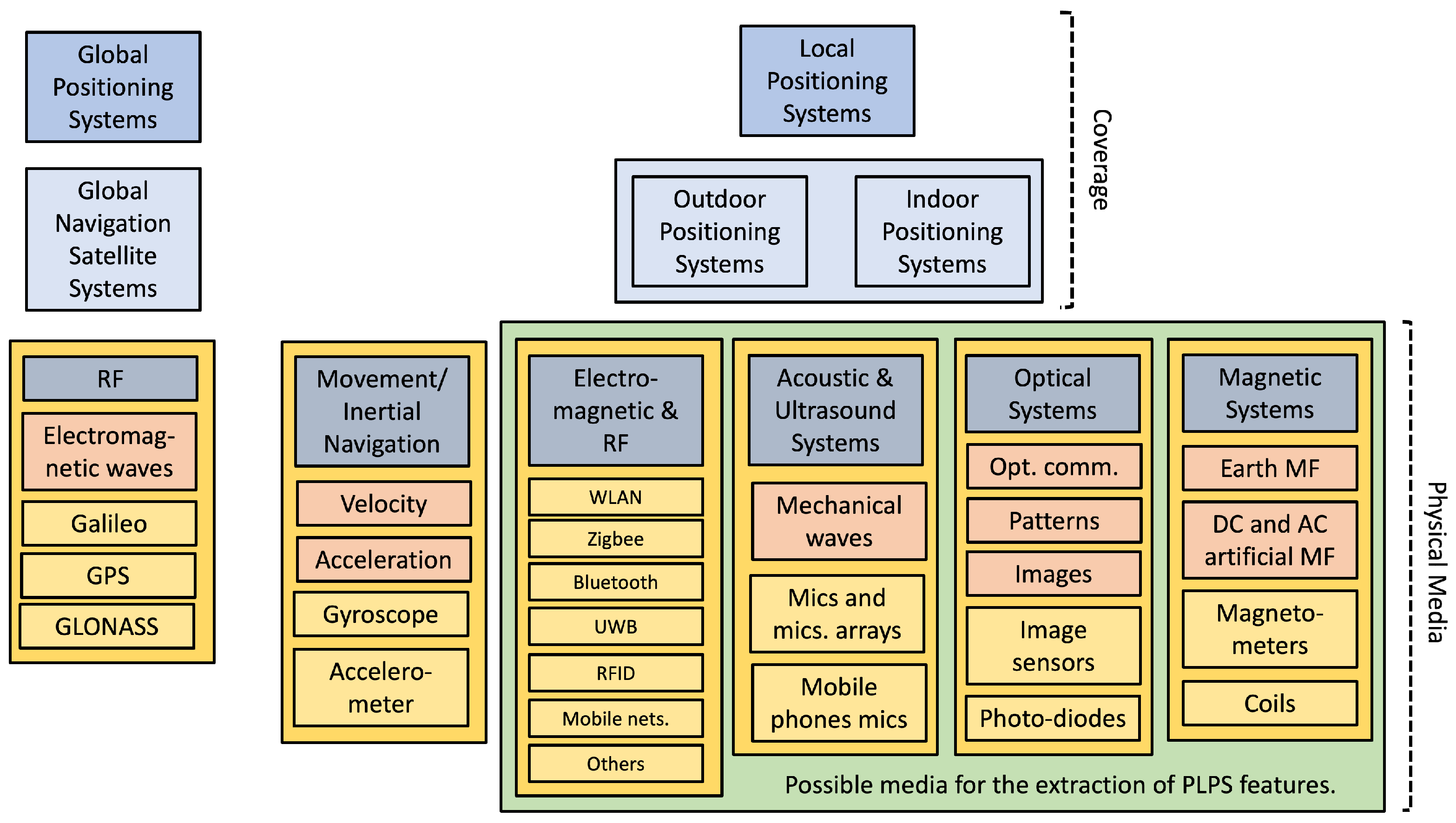
2. Power Line Positioning Systems: Characteristics, Properties and Categories
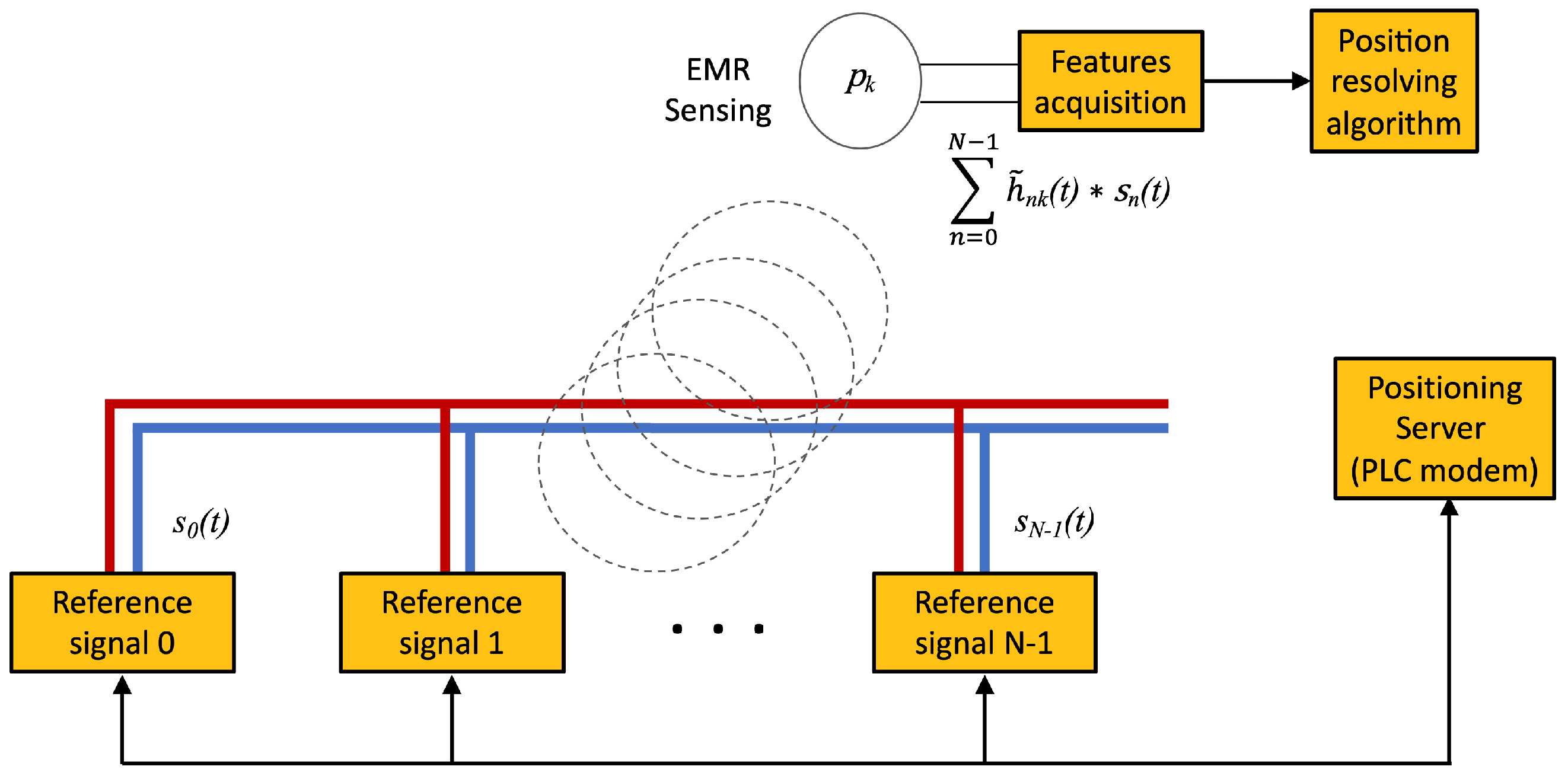
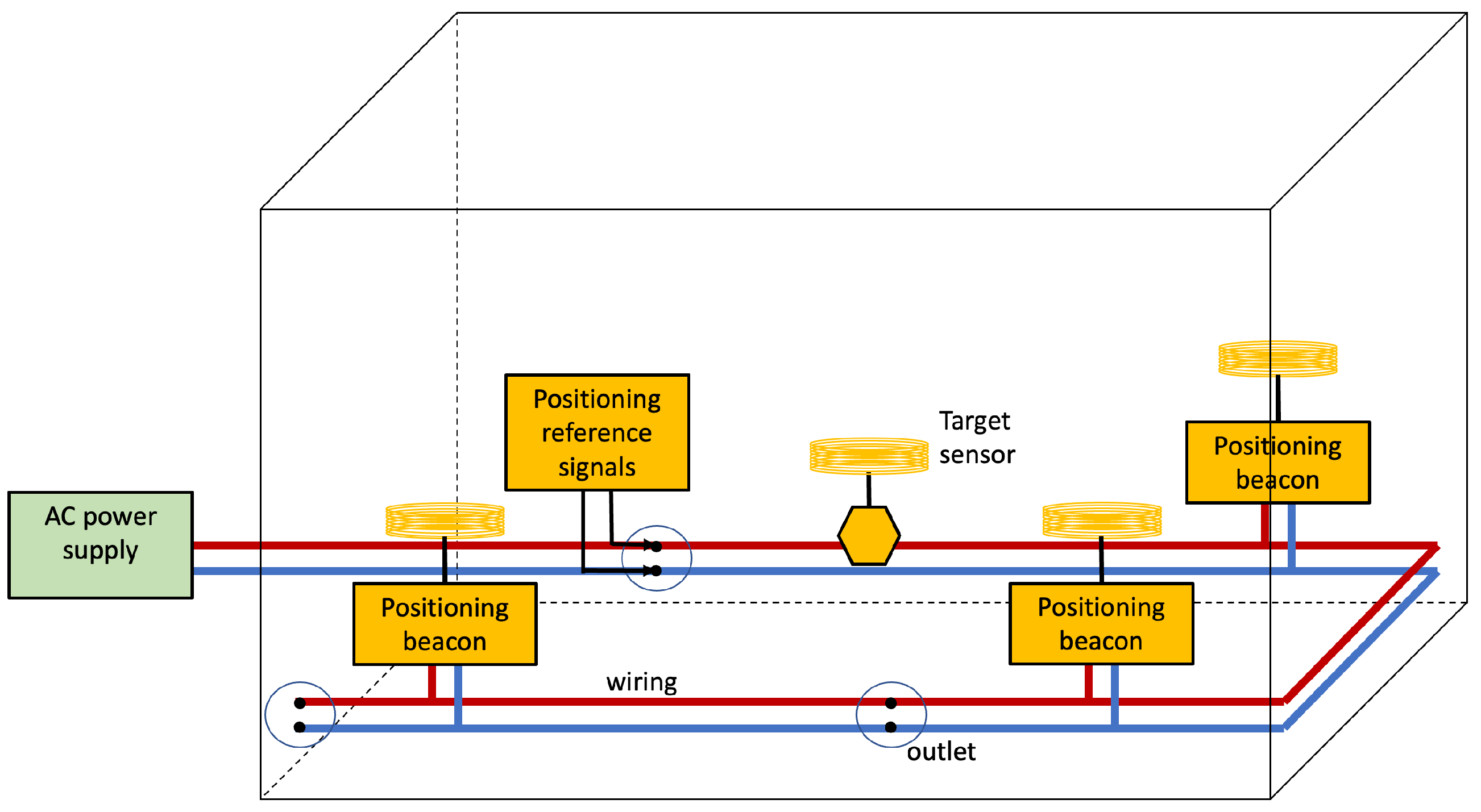
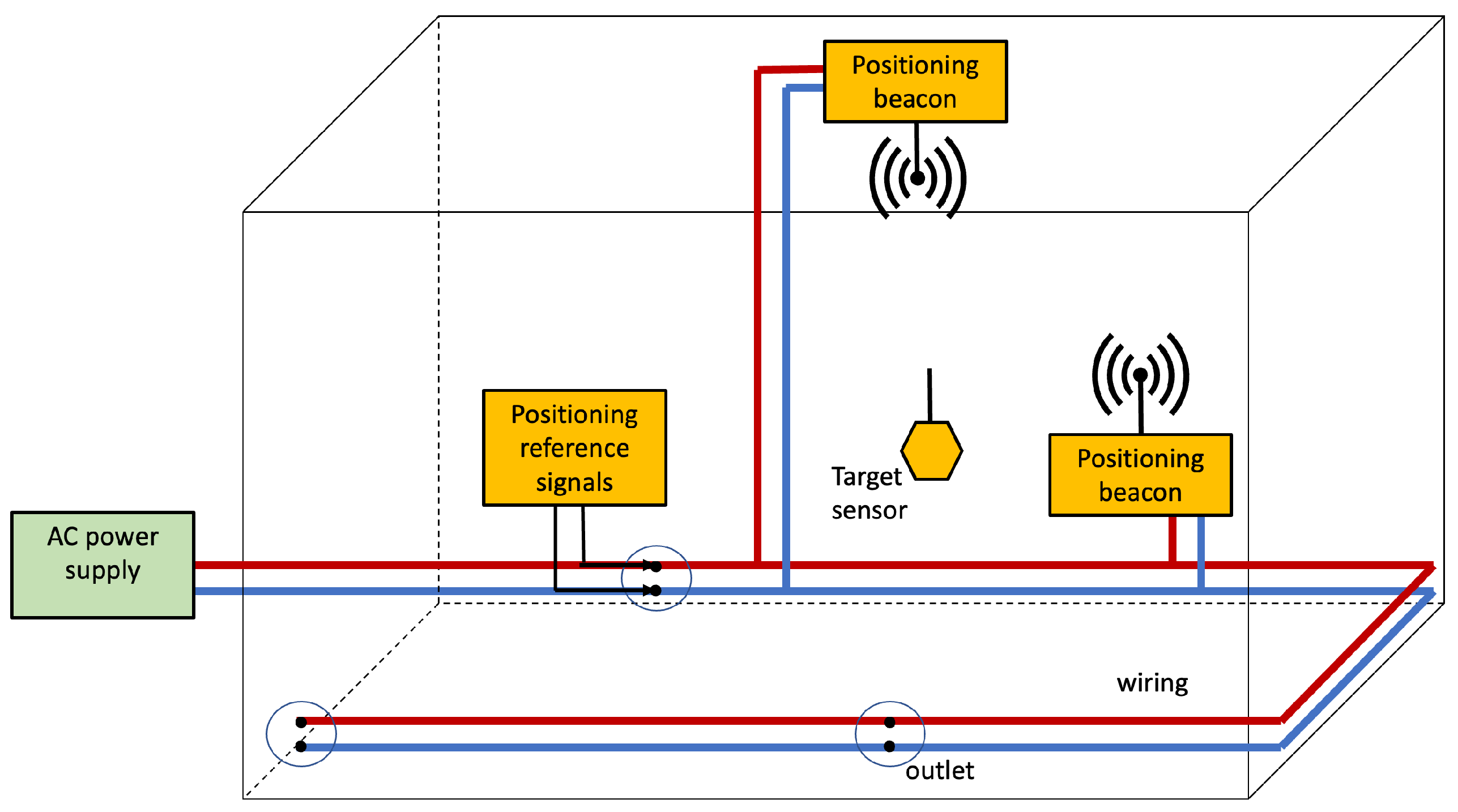
2.1. Positioning Reference Signals
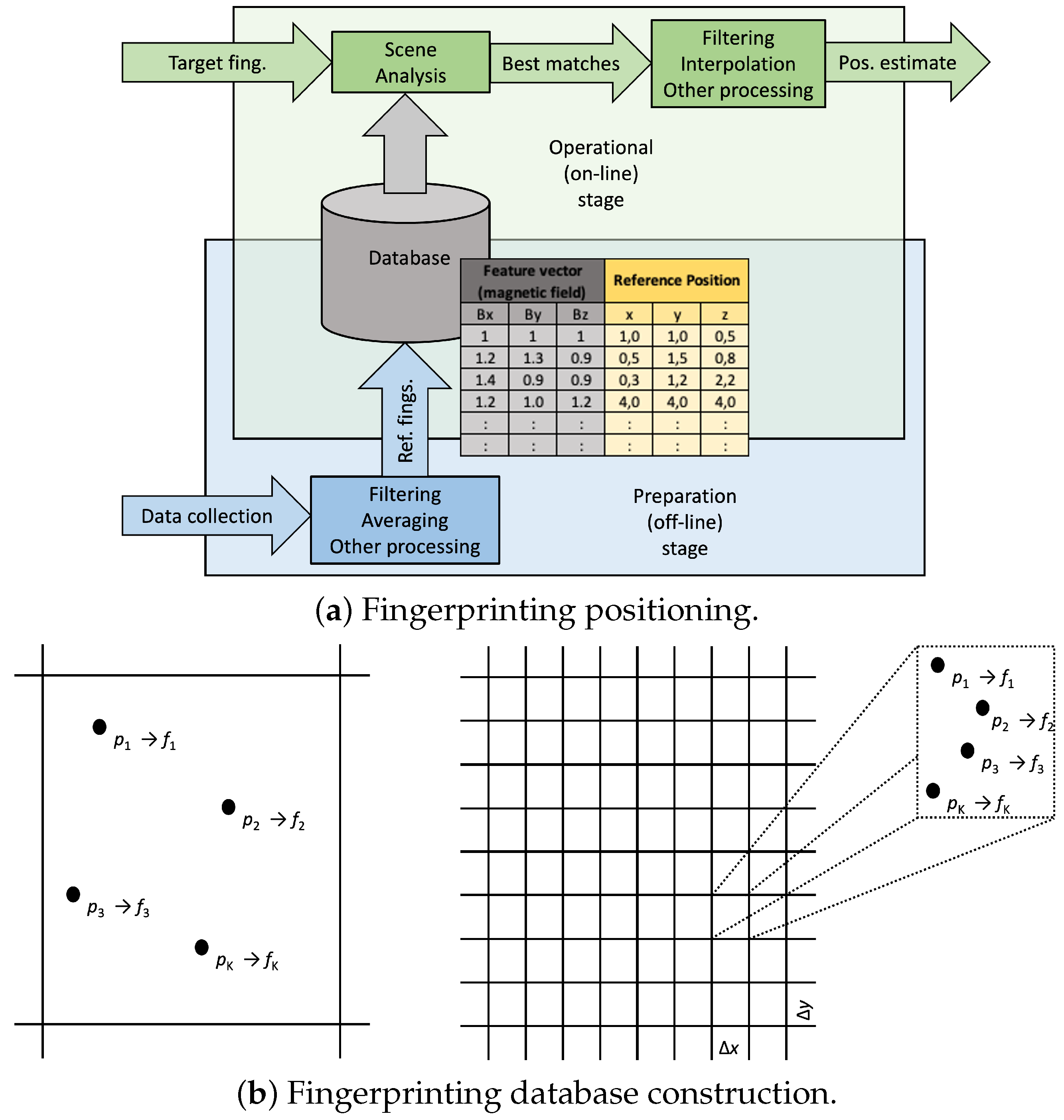
2.2. Collecting the Features
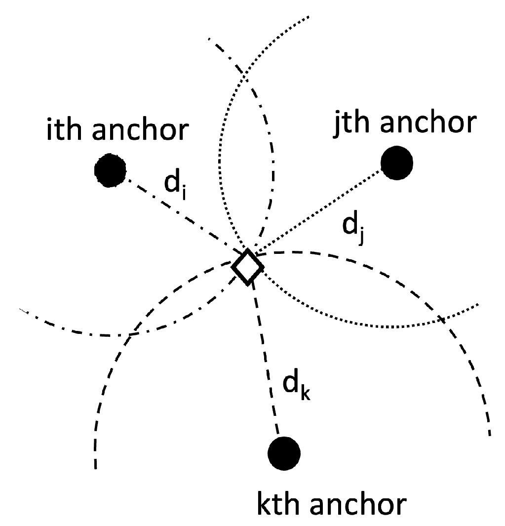
2.3. Computing the Position Estimate
2.4. System Categories
2.5. PLPS Examples
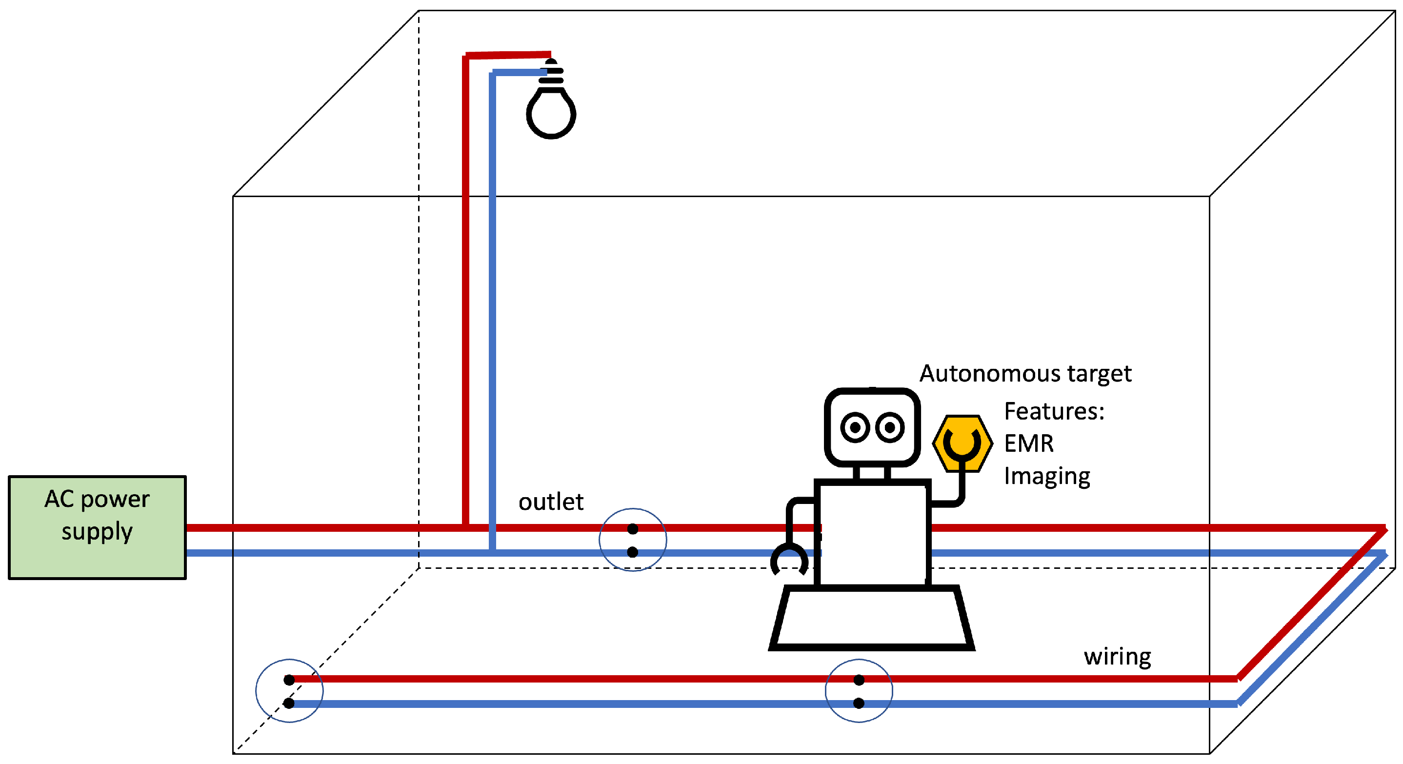
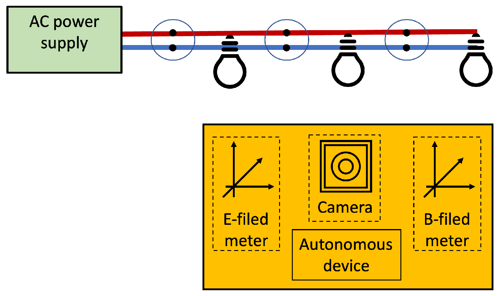
3. Infra-Less Target-Based (Self) PLPS
3.1. Examples
3.1.1. Autonomous Plugging-In
3.1.2. Autonomous Pearching
3.1.3. AC EMR Fingerprinting Positioning
3.2. Positioning Features
3.3. Sensors to Embark
3.4. Resolving the Position
3.5. Applications
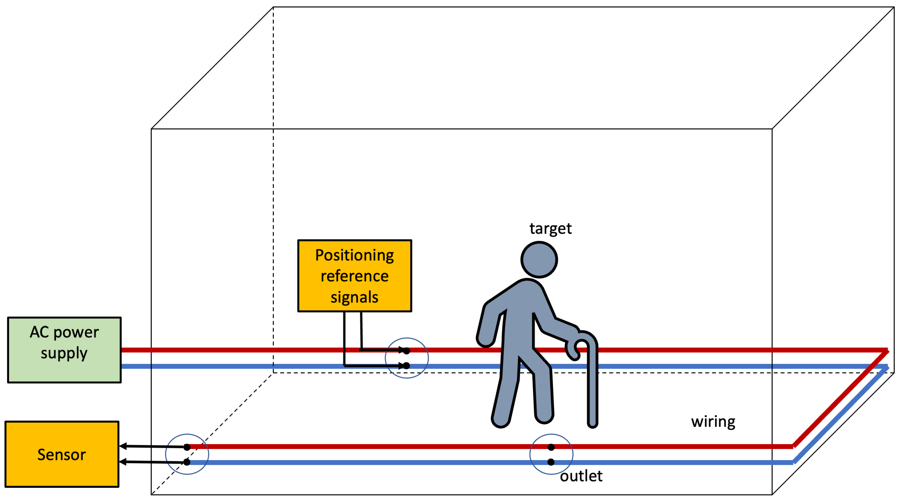
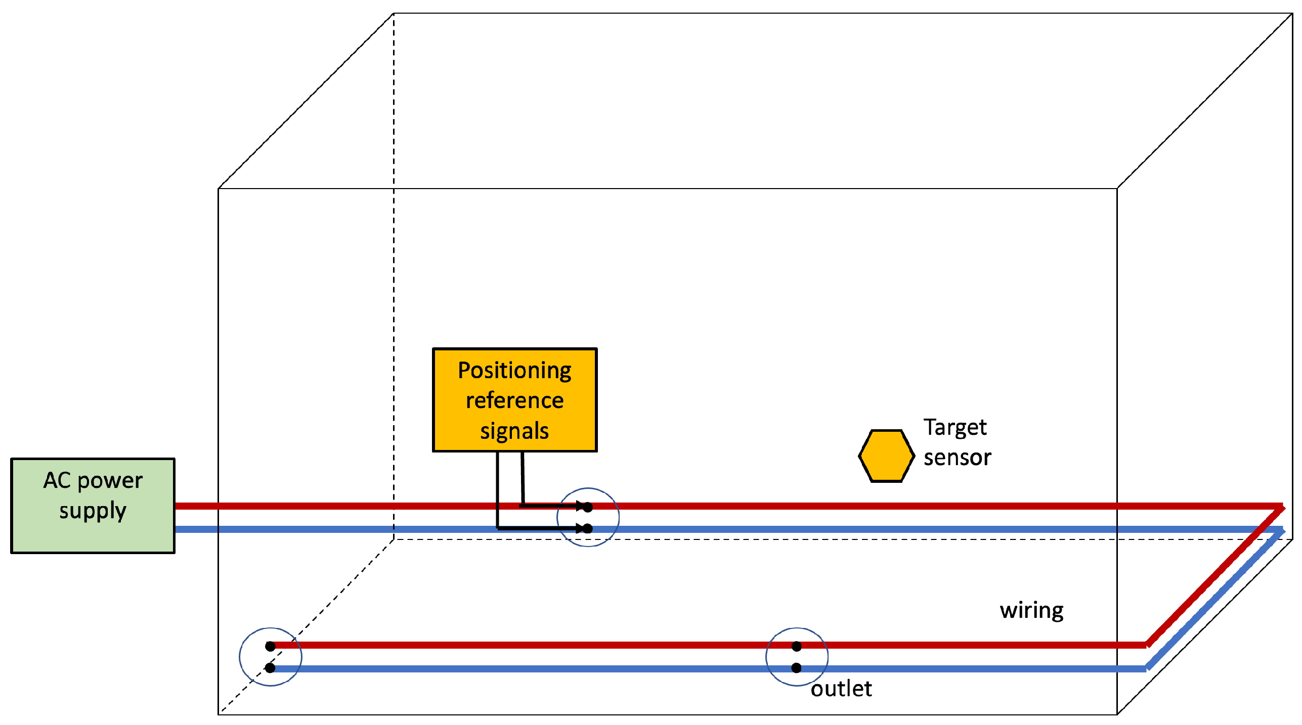
4. Infra-Based Target-Obtuse (Unobtrusive) PLPS
4.1. An Example
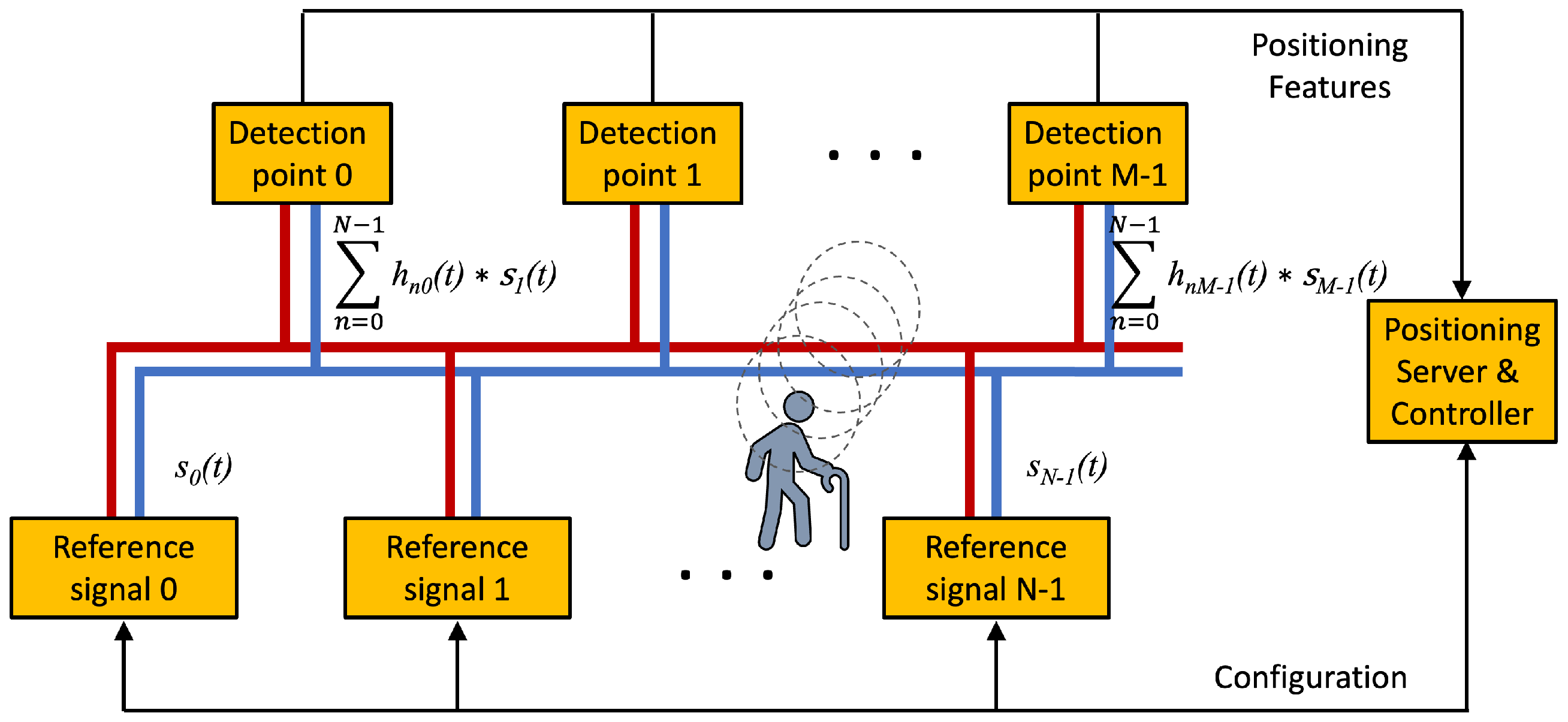
4.2. System Model
Using PLC for IBTO PLPS
4.3. Positioning Features
4.4. Resolving the Position
4.5. Applications
5. Infra-Based Target-Based PLPS
5.1. Examples
5.2. System Model
5.3. Positioning Features
5.4. IBTB PLPS Using PLC
5.5. Sensing the PLCWC
5.6. Resolving the Position
5.7. Hybrid PLPS Using PLC Technology
5.7.1. PLC–IPS Using Magnetic Beacons
5.7.2. PLC–Wireless Integration
5.7.3. PLC–VLC Integration
5.8. Applications
6. Some Comments on the Deployment of PLPS and Application Scenarios
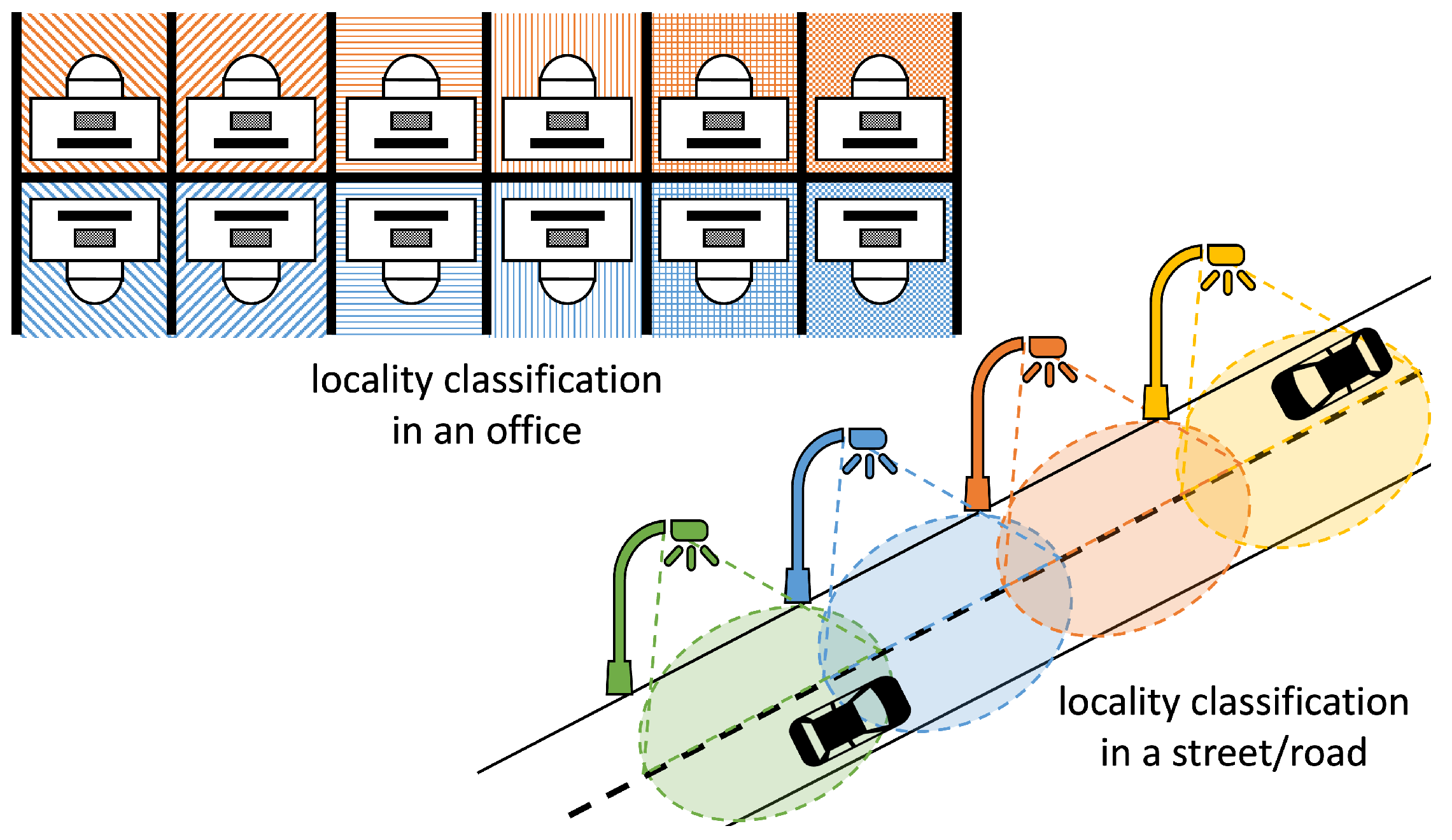
6.1. Unobtrusive PLPS Using PLC
6.2. Positioning in Ships
6.3. Underground Mines
6.4. Industry 4.0
6.5. Hybrid and Fusion PLPS
7. Conclusions
Author Contributions
Funding
Conflicts of Interest
Abbreviations
| AC | Alternate Current |
| ARIB | Association of Radio Industries and Business |
| BB | Broad Band |
| BPSK | Binary Phase Shift Keying |
| CENELEC | European Committee for Electrotechnical Standardization |
| CM | Common Mode |
| CSI | Channel State Information |
| DC | Direct Current |
| EMF | Electromagnetic Field |
| EMR | Electromagnetic Radiation |
| FCC | Federal Communications Commission |
| FFT | Fast Fourier Transform |
| GPS | Global Positioning Systems |
| HPCLWC | Hybrid PLC-Wireless Channel |
| HV | High Voltage |
| IBTB | Infra-Based Target-Based |
| IBTO | Infra-Based Target-Obtuse |
| ILTB | Infra-Less Target-Based |
| IEEE | Institute of Electrical and Electronic Engineers |
| IFFT | Inverse Fast Fourier Transform |
| IPS | Indoor Positioning System |
| LAN | Local Area Networks |
| LC | Locality Classification |
| LV | Low Voltage |
| OFDM | Orthogonal Frequency Division Multiplexing |
| MB | Medium Band |
| MV | Medium Voltage |
| NB | Narrow Band |
| PAM | Pulse Amplitude Modulation |
| PLC | Power Line Communication |
| PLC-IPS | PLC-Based IPS |
| PLCWC | PLC Wireless Channel |
| PLPS | Power Line Positioning System |
| QAM | Quadrature Amplitude Modulation |
| QPSK | Quadrature Phase Shift Keying |
| RF | Radio Frequency |
| SLaM | Simultaneous Localization and Mapping |
| UAV | Unmanned Aerial Vehicle |
| UNB | Ultra Narrow Band |
| VLC | Visible Light Communication |
| VLP | Visible Light Positioning |
Appendix A. PLC Categories

| FFT OFDM PHY | Wavelet OFDM PHY | |
|---|---|---|
| Forward Error Correction | Turbo-convolutional coding | Reed–Solomon coding |
| Convolutional coding | ||
| Concatenated coding | ||
| Low-Density Parity-Check convolutional coding (optional) | ||
| Primary Modulation | BPSK, QPSK, 8-QAM to | 2-PAM to 16-PAM, 32-PAM (optional) |
| 1024-QAM, 4096-QAM (optional) | ||
| Subchannels (C) | 4096 (917 active) | 512, 1024, 2048 |
| Prototype Filter Length (2qC) | – | q = 2, 3, 4 |
| Frequency Band | 1.8–50 MHz | 1.8 MHz–28 MHz, 1.8 MHz–50 MHz (optional) |
| Symbol Length (μs) | 40.96 | 8.192, 16.384 (optional), 32.768 (optional) |
Appendix A.1. Broadband-PLC

Appendix A.2. Medium-Band-PLC
Appendix A.3. Narrowband-PLC
References
- Zekavat, R.; Buehrer, R.M. Handbook of Position Location: Theory, Practice and Advances; John Wiley & Sons: Hoboken, NJ, USA, 2011; Volume 27. [Google Scholar]
- Campos, R.S.; Lovisolo, L. RF Positioning: Fundamentals, Applications, and Tools; Artech House: United States of America, 2015. [Google Scholar]
- Zekavat, S.R.; Buehrer, R.M.; Durgin, G.D.; Lovisolo, L.; Wang, Z.; Goh, S.T.; Ghasemi, A. An Overview on Position Location: Past, Present, Future. Int. J. Wirel. Inf. Netw. 2021, 28, 45–76. [Google Scholar] [CrossRef]
- Pannuto, P.; Kempke, B.; Chuo, L.X.; Blaauw, D.; Dutta, P. Harmonium: Ultra wideband pulse generation with bandstitched recovery for fast, accurate, and robust indoor localization. ACM Trans. Sens. Netw. (TOSN) 2018, 14, 1–29. [Google Scholar] [CrossRef]
- Becker, C.; Dürr, F. On location models for ubiquitous computing. Pers. Ubiquitous Comput. 2005, 9, 20–31. [Google Scholar] [CrossRef]
- Mautz, R. Indoor Positioning Technologies; ETH Zurich, Department of Civil, Environmental and Geomatic Engineering: Zurich, Switzerland, 2012. [Google Scholar]
- Harle, R. A survey of indoor inertial positioning systems for pedestrians. IEEE Commun. Surv. Tutor. 2013, 15, 1281–1293. [Google Scholar] [CrossRef]
- Ijaz, F.; Yang, H.K.; Ahmad, A.W.; Lee, C. Indoor positioning: A review of indoor ultrasonic positioning systems. In Proceedings of the IEEE 2013 15th International Conference on Advanced Communications Technology (ICACT), Guilin, China, 17 November 2013; pp. 1146–1150. [Google Scholar]
- Davidson, P.; Piché, R. A survey of selected indoor positioning methods for smartphones. IEEE Commun. Surv. Tutor. 2016, 19, 1347–1370. [Google Scholar] [CrossRef]
- Brena, R.F.; García-Vázquez, J.P.; Galván-Tejada, C.E.; Muñoz-Rodríguez, D.; Vargas-Rosales, C.; Fangmeyer, J. Evolution of indoor positioning technologies: A survey. J. Sens. 2017, 2017, 2630413. [Google Scholar] [CrossRef]
- Luo, J.; Fan, L.; Li, H. Indoor positioning systems based on visible light communication: State of the art. IEEE Commun. Surv. Tutor. 2017, 19, 2871–2893. [Google Scholar] [CrossRef]
- Pasku, V.; De Angelis, A.; De Angelis, G.; Arumugam, D.D.; Dionigi, M.; Carbone, P.; Moschitta, A.; Ricketts, D.S. Magnetic field-based positioning systems. IEEE Commun. Surv. Tutor. 2017, 19, 2003–2017. [Google Scholar] [CrossRef]
- Tariq, Z.B.; Cheema, D.M.; Kamran, M.Z.; Naqvi, I.H. Non-GPS positioning systems: A survey. ACM Comput. Surv. (CSUR) 2017, 50, 1–34. [Google Scholar] [CrossRef]
- Ferreira, A.F.G.G.; Fernandes, D.M.A.; Catarino, A.P.; Monteiro, J.L. Localization and positioning systems for emergency responders: A survey. IEEE Commun. Surv. Tutor. 2017, 19, 2836–2870. [Google Scholar] [CrossRef]
- Zhuang, Y.; Hua, L.; Qi, L.; Yang, J.; Cao, P.; Cao, Y.; Wu, Y.; Thompson, J.; Haas, H. A survey of positioning systems using visible LED lights. IEEE Commun. Surv. Tutor. 2018, 20, 1963–1988. [Google Scholar] [CrossRef]
- Lovisolo, L.; Tcheou, M.P.; Ávila, F.R. Visible Light-Based Communication and Localization. In Handbook of Position Location: Theory, Practice, and Advances, 2nd ed.; John Wiley & Sons: Hoboken, NJ, USA, 2018; pp. 1121–1164. [Google Scholar]
- Zafari, F.; Gkelias, A.; Leung, K.K. A survey of indoor localization systems and technologies. IEEE Commun. Surv. Tutor. 2019, 21, 2568–2599. [Google Scholar] [CrossRef]
- Lam, E.W.; Little, T.D. Visible light positioning for location-based services in Industry 4.0. In Proceedings of the IEEE 2019 16th International Symposium on Wireless Communication Systems (ISWCS), Oulu, Finland, 21 October 2019; pp. 345–350. [Google Scholar]
- Li, C.T.; Cheng, J.C.; Chen, K. Top 10 technologies for indoor positioning on construction sites. Autom. Constr. 2020, 118, 103309. [Google Scholar] [CrossRef]
- Rafsanjani, H.N.; Ghahramani, A. Towards utilizing internet of things (IoT) devices for understanding individual occupants’ energy usage of personal and shared appliances in office buildings. J. Build. Eng. 2020, 27, 100948. [Google Scholar] [CrossRef]
- Rocamora, J.M.; Ho, I.W.H.; Mak, W.M.; Lau, A.P.T. Survey of CSI fingerprinting-based indoor positioning and mobility tracking systems. IET Signal Process. 2020, 14, 407–419. [Google Scholar] [CrossRef]
- Seguel, F.; Palacios-Játiva, P.; Azurdia-Meza, C.A.; Krommenacker, N.; Charpentier, P.; Soto, I. Underground mine positioning: A review. IEEE Sens. J. 2021, 22, 4755–4771. [Google Scholar] [CrossRef]
- Kim Geok, T.; Zar Aung, K.; Sandar Aung, M.; Thu Soe, M.; Abdaziz, A.; Pao Liew, C.; Hossain, F.; Tso, C.P.; Yong, W.H. Review of indoor positioning: Radio wave technology. Appl. Sci. 2021, 11, 279. [Google Scholar] [CrossRef]
- Patel, S.N.; Truong, K.N.; Abowd, G.D. Powerline positioning: A practical sub-room-level indoor location system for domestic use. In Proceedings of the International Conference on Ubiquitous Computing, Orange County, CA, USA, 17–21 September 2006; Springer: Berlin/Heidelberg, Germany, 2006; pp. 441–458. [Google Scholar]
- Lampe, L.; Tonello, A.M.; Swart, T.G. Power Line Communications: Principles, Standards and Applications From Multimedia to Smart Grid; John Wiley & Sons: Hoboken, NJ, USA, 2016. [Google Scholar]
- Campos, R.S.; Lovisolo, L. RF fingerprinting location techniques. In Handbook of Position Location: Theory, Practice, and Advances; John Wiley & Sons: Hong Kong, China, 2011; pp. 487–520. [Google Scholar]
- Al-Ammar, M.A.; Alhadhrami, S.; Al-Salman, A.; Alarifi, A.; Al-Khalifa, H.S.; Alnafessah, A.; Alsaleh, M. Comparative survey of indoor positioning technologies, techniques, and algorithms. In Proceedings of the IEEE 2014 International Conference on Cyberworlds, Kanpur, India, 27 February 2014; pp. 245–252. [Google Scholar]
- Mudriievskyi, S. Power line communications: State of the art in research, development and application. AEU-Int. J. Electron. Commun. 2014, 68, 575–577. [Google Scholar] [CrossRef]
- Cano, C.; Pittolo, A.; Malone, D.; Lampe, L.; Tonello, A.M.; Dabak, A.G. State of the art in power line communications: From the applications to the medium. IEEE J. Sel. Areas Commun. 2016, 34, 1935–1952. [Google Scholar] [CrossRef]
- López, G.; Matanza, J.; De La Vega, D.; Castro, M.; Arrinda, A.; Moreno, J.I.; Sendín, A. The role of power line communications in the smart grid revisited: Applications, challenges, and research initiatives. IEEE Access 2019, 7, 117346–117368. [Google Scholar] [CrossRef]
- Tsuzuki, S.; Takeichi, N.; Hamada, M.; Yamada, Y. A Proposal of Synchronization Beacon Systems over Power-line for Indoor Fine-Grained Localization. In Proceedings of the 2006 IEEE International Symposium on Power Line Communications and its Applications, Orlando, FL, USA, 30 October 2006; pp. 143–148. [Google Scholar]
- Mayton, B.; LeGrand, L.; Smith, J.R. Robot, feed thyself: Plugging in to unmodified electrical outlets by sensing emitted AC electric fields. In Proceedings of the 2010 IEEE International Conference on Robotics and Automation, Anchorage, AK, USA, 4–8 May 2010; pp. 715–722. [Google Scholar]
- Society of Automotive Engineers International. Wireless Power Transfer for Light-Duty Plug-In/Electric Vehicles and Alignment Methodology; SAE Recommended Practice J2954 (rev. 201904); Society of Automotive Engineers International: Troy, MI, USA, 2019. [Google Scholar]
- Seong, J.Y.; Lee, S.S. A Study on Precise Positioning for an Electric Vehicle Wireless Power Transfer System Using a Ferrite Antenna. Electronics 2020, 9, 1289. [Google Scholar] [CrossRef]
- Zhou, T.; Zhang, Y.; Chen, X.; Zhang, P.; Zhang, L. E-loc: Indoor localization through building electric wiring. In Proceedings of the 16th ACM/IEEE International Conference on Information Processing in Sensor Networks, Pittsburgh, PA, USA, 18–21 April 2017; pp. 311–312. [Google Scholar]
- Kiedrowski, P. Toward more efficient and more secure last mile smart metering and smart lighting communication systems with the use of PLC/RF hybrid technology. Int. J. Distrib. Sens. Netw. 2015, 11, 675926. [Google Scholar] [CrossRef]
- de Mello Brandao Abdo Dib, L.; Fernandes, V.; de Filomeno, M.L.; Ribeiro, M.V. Hybrid PLC/wireless communication for smart grids and internet of things applications. IEEE Internet Things J. 2017, 5, 655–667. [Google Scholar]
- Ding, W.; Yang, F.; Yang, H.; Wang, J.; Wang, X.; Zhang, X.; Song, J. A hybrid power line and visible light communication system for indoor hospital applications. Comput. Ind. 2015, 68, 170–178. [Google Scholar] [CrossRef]
- Gheth, W.; Rabie, K.M.; Adebisi, B.; Ijaz, M.; Harris, G. Performance analysis of integrated power-line/visible-light communication systems with AF relaying. In Proceedings of the 2018 IEEE Global Communications Conference (GLOBECOM), Abu Dhabi, United Arab Emirates, 9–13 December 2018; pp. 1–6. [Google Scholar]
- Jani, M.; Garg, P.; Gupta, A. Performance analysis of a co-operative PLC/VLC system with multiple access points for indoor broadcasting. AEU-Int. J. Electron. Commun. 2019, 103, 64–73. [Google Scholar] [CrossRef]
- Ndjiongue, A.R.; Shongwe, T.; Ferreira, H.C.; Ngatched, T.N.; Vinck, A.H. Cascaded PLC-VLC channel using OFDM and CSK techniques. In Proceedings of the 2015 IEEE Global Communications Conference (GLOBECOM), San Diego, CA, USA, 6–10 December 2015; pp. 1–6. [Google Scholar]
- Bagepalli, A.; Zamora, M.; Sánchez, D. Autonomous Self-Guiding Wall Charging Robot. 2005. Available online: https://www.slideserve.com/libitha/autonomous-self-guiding-wall-charging-robot (accessed on 3 October 2022).
- Moore, J.; Tedrake, R. Powerline perching with a fixed-wing UAV. In Proceedings of the AIAA Infotech@ Aerospace Conference and AIAA Unmanned... Unlimited Conference, Seattle, WA, USA, 6–9 April 2009; p. 1959. [Google Scholar]
- Moore, J.; Tedrake, R. Magnetic localization for perching UAVs on powerlines. In Proceedings of the 2011 IEEE/RSJ International Conference on Intelligent Robots and Systems, San Francisco, CA, USA, 25–30 September 2011; pp. 2700–2707. [Google Scholar]
- Lu, C.X.; Li, Y.; Zhao, P.; Chen, C.; Xie, L.; Wen, H.; Tan, R.; Trigoni, N. Simultaneous localization and mapping with power network electromagnetic field. In Proceedings of the 24th Annual International Conference on Mobile Computing and Networking, New Delhi, India, 29 Octorber–2 November 2018; pp. 607–622. [Google Scholar]
- Zhou, T.; Zhang, Y.; Chen, X.; Mosalam, K.M.; Noh, H.Y.; Zhang, P.; Zhang, L. P-Loc: A device-free indoor localization system utilizing building power-line network. In Proceedings of the 2019 ACM International Joint Conference on Pervasive and Ubiquitous Computing and Proceedings of the 2019 ACM International Symposium on Wearable Computers, New York, NY, USA, 8 August 2019; pp. 611–615. [Google Scholar]
- Stuntebeck, E.P.; Patel, S.N.; Robertson, T.; Reynolds, M.S.; Abowd, G.D. Wideband powerline positioning for indoor localization. In Proceedings of the 10th International Conference on Ubiquitous Computing, Seoul, Korea, 21–24 September 2008; pp. 94–103. [Google Scholar]
- De Angelis, G.; Pasku, V.; De Angelis, A.; Dionigi, M.; Mongiardo, M.; Moschitta, A.; Carbone, P. An indoor AC magnetic positioning system. IEEE Trans. Instrum. Meas. 2015, 64, 1275–1283. [Google Scholar] [CrossRef]
- Pasku, V.; De Angelis, A.; Dionigi, M.; De Angelis, G.; Moschitta, A.; Carbone, P. A positioning system based on low-frequency magnetic fields. IEEE Trans. Ind. Electron. 2015, 63, 2457–2468. [Google Scholar] [CrossRef]
- Hehn, M.; Sippel, E.; Carlowitz, C.; Vossiek, M. High-accuracy localization and calibration for 5-DoF indoor magnetic positioning systems. IEEE Trans. Instrum. Meas. 2019, 68, 4135–4145. [Google Scholar] [CrossRef]
- Degauque, P.; Laly, P.; Degardin, V.; Lienard, M.; Diquelou, L. Compromising electromagnetic field radiated by in-house PLC lines. In Proceedings of the 2010 IEEE Global Telecommunications Conference GLOBECOM 2010, Miami, FL, USA, 6–10 October 2010; pp. 1–5. [Google Scholar]
- Degardin, V.; Laly, P.; Lienard, M.; Degauque, P. Compromising radiated emission from a power line communication cable. J. Commun. Softw. Syst. 2011, 7, 16–21. [Google Scholar] [CrossRef]
- Oliveira, T.; Andrade, F.; Picorone, A.; Latchman, H.; Netto, S.L.; Ribeiro, M.V. Characterization of hybrid communication channel in indoor scenario. J. Commun. Inf. Syst. (JCIS) 2016, 31. [Google Scholar] [CrossRef]
- Barmada, S.; Tucci, M.; Raugi, M.; Dionigi, M.; Mezzanotte, P. Experimental validation of a hybrid wireless power transfer-power line communication system. In Proceedings of the 2016 International Symposium on Power Line Communications and its Applications (ISPLC), Bottrop, Germany, 20–23 March 2016; pp. 37–41. [Google Scholar]
- Ralchenko, M.; Roper, M. VLF magnetic positioning in multistory parking garages. In Proceedings of the 2018 International Conference on Indoor Positioning and Indoor Navigation (IPIN), Nantes, France, 24–27 September 2018; pp. 1–8. [Google Scholar]
- Haverinen, J.; Kemppainen, A. Global indoor self-localization based on the ambient magnetic field. Robot. Auton. Syst. 2009, 57, 1028–1035. [Google Scholar] [CrossRef]
- Gozick, B.; Subbu, K.P.; Dantu, R.; Maeshiro, T. Magnetic maps for indoor navigation. IEEE Trans. Instrum. Meas. 2011, 60, 3883–3891. [Google Scholar] [CrossRef]
- Subbu, K.P.; Gozick, B.; Dantu, R. LocateMe: Magnetic-fields-based indoor localization using smartphones. ACM Trans. Intell. Syst. Technol. (TIST) 2013, 4, 1–27. [Google Scholar] [CrossRef]
- Rodríguez, D.P.N.; Apolinário, J.A.; Biscainho, L.W.P. Audio authenticity: Detecting ENF discontinuity with high precision phase analysis. IEEE Trans. Inf. Forensics Secur. 2010, 5, 534–543. [Google Scholar] [CrossRef]
- Martens, S.M.; Mischi, M.; Oei, S.G.; Bergmans, J.W. An improved adaptive power line interference canceller for electrocardiography. IEEE Trans. Biomed. Eng. 2006, 53, 2220–2231. [Google Scholar] [CrossRef]
- Li, Y.; Tan, R.; Yau, D.K. Natural timestamping using powerline electromagnetic radiation. In Proceedings of the 2017 16th ACM/IEEE International Conference on Information Processing in Sensor Networks (IPSN), Nantes, France, 24–27 September 2017; pp. 55–66. [Google Scholar]
- Li, Y.; Tan, R.; Yau, D.K. Natural timestamps in powerline electromagnetic radiation. ACM Trans. Sens. Netw. (TOSN) 2018, 14, 1–30. [Google Scholar] [CrossRef]
- Ripka, P. Magnetic Sensors and Magnetometers; Artech House: Washington, DC, USA, 2021. [Google Scholar]
- Filippopoulos, G.; Tsanakas, D. Analytical calculation of the magnetic field produced by electric power lines. IEEE Trans. Power Deliv. 2005, 20, 1474–1482. [Google Scholar] [CrossRef]
- Kosba, A.E.; Saeed, A.; Youssef, M. RASID: A robust WLAN device-free passive motion detection system. In Proceedings of the 2012 IEEE International Conference on Pervasive Computing and Communications, Lugano, Switzerland, 19–23 March 2012; pp. 180–189. [Google Scholar]
- Deak, G.; Curran, K.; Condell, J. A survey of active and passive indoor localisation systems. Comput. Commun. 2012, 35, 1939–1954. [Google Scholar] [CrossRef]
- das Chagas, A.O.S.; Lovisolo, L.; Tcheou, M.P. Detecçao de Risco de Queda no Ambiente Hospitalar a partir da Informaçao do Estado do Canal Sem-Fio. In Proceedings of the Brazilian Congress on Computational Intelligence (CBIC), Ipojuca, Brazil, 8–11 September 2021. [Google Scholar]
- Seifeldin, M.; Saeed, A.; Kosba, A.E.; El-Keyi, A.; Youssef, M. Nuzzer: A large-scale device-free passive localization system for wireless environments. IEEE Trans. Mob. Comput. 2012, 12, 1321–1334. [Google Scholar] [CrossRef]
- Jin, Z.; Bu, Y.; Liu, J.; Wang, X.; An, N. Development of Indoor Localization System for Elderly Care Based on Device-Free Passive Method. In Proceedings of the 2015 Sixth International Conference on Intelligent Systems Design and Engineering Applications (ISDEA), Surabaya, Indonesia, 20–21 May 2015; pp. 328–331. [Google Scholar]
- Saeed, A.; Kosba, A.E.; Youssef, M. Ichnaea: A low-overhead robust WLAN device-free passive localization system. IEEE J. Sel. Top. Signal Process. 2013, 8, 5–15. [Google Scholar] [CrossRef]
- Chow, K.H.; He, S.; Tan, J.; Chan, S.H.G. Efficient locality classification for indoor fingerprint-based systems. IEEE Trans. Mob. Comput. 2018, 18, 290–304. [Google Scholar] [CrossRef]
- Xiao, J.; Wu, K.; Yi, Y.; Wang, L.; Ni, L.M. Pilot: Passive device-free indoor localization using channel state information. In Proceedings of the 2013 IEEE 33rd International Conference on Distributed Computing Systems, Philadelphia, PA, USA, 8–11 July 2013; pp. 236–245. [Google Scholar]
- Dias, P.V.G.; Costa, E.D.M.; Tcheou, M.P.; Lovisolo, L. Fall detection monitoring system with position detection for elderly at indoor environments under supervision. In Proceedings of the 2016 8th IEEE Latin-American Conference on Communications (LATINCOM), Medellin, Colombia, 15–17 November 2016; pp. 1–6. [Google Scholar]
- Djaja-Josko, V. Presence and Fall Detection in Confined Indoor Environments Using Multiple UWB Transceivers. In Proceedings of the 2018 26th Telecommunications Forum (TELFOR), Belgrade, Serbia, 20–21 November 2018; pp. 1–4. [Google Scholar]
- Rashid, K.M.; Louis, J.; Fiawoyife, K.K. Wireless electric appliance control for smart buildings using indoor location tracking and BIM-based virtual environments. Autom. Constr. 2019, 101, 48–58. [Google Scholar] [CrossRef]
- Aipperspach, R.; Woodruff, A.; Anderson, K.; Hooker, B. Maps of Our Lives: Sensing People and Objects Together in the Home; EECS Department, University of California: Berkeley, CA, USA, 2005; pp. 1–11. [Google Scholar]
- Zhan, Y.; Haddadi, H. MoSen: Activity Modelling in Multiple-Occupancy Smart Homes. arXiv 2021, arXiv:2101.00235. [Google Scholar]
- Patel, S.N.; Abowd, G.D.; Reynolds, M.S.; Robertson, T.; Stuntebeck, E. Sub Room Level Indoor Location System Using Wideband Power Line Positioning. U.S. Patent 8,494,762, 23 July 2013. [Google Scholar]
- Patel, S.N.; Truong, K.N.; Abowd, G.D.; Robertson, T.; Reynolds, M.S. Sub-Room-Level Indoor Location System Using Power Line Positioning. U.S. Patent 8,392,107, 5 March 2013. [Google Scholar]
- Nishikawa, K.i.; Higashino, T.; Tsukamoto, K. A new position detection method using leaky coaxial cable. IEICE Electron. Express 2008, 5, 285–290. [Google Scholar] [CrossRef][Green Version]
- Weber, M.; Birkel, U.; Collmann, R. Indoor RF Fingerprinting using leaky feeder cable considering environmental changes. In Proceedings of the 6th International Conference on Mobile Technology, Application & Systems, Macau, China, 12–15 October 2009; pp. 1–6. [Google Scholar]
- See, K.Y.; So, P.L.; Kamarul, A.; Gunawan, E. Radio-frequency common-mode noise propagation model for power-line cable. IEEE Trans. Power Deliv. 2005, 20, 2443–2449. [Google Scholar] [CrossRef]
- Vukicevic, A.; Rubinstein, M.; Rachidi, F.; Bermúdez, J.L. On the mechanisms of differential-mode to common-mode conversion in the broadband over power line (BPL) frequency band. In Proceedings of the 2006 17th International Zurich Symposium on Electromagnetic Compatibility, Singapore, 27 February–3 March 2006; pp. 658–661. [Google Scholar]
- Favre, P.; Candolfi, C.; Schneider, M.; Rubinstein, M.; Krahenbuehl, P.; Vukicevic, A. Common mode current and radiations mechanisms in PLC networks. In Proceedings of the 2007 IEEE International Symposium on Power Line Communications and Its Applications, Pisa, Italy, 26–28 March 2007; pp. 348–354. [Google Scholar]
- Sugiura, A.; Kami, Y. Generation and propagation of common-mode currents in a balanced two-conductor line. IEEE Trans. Electromagn. Compat. 2011, 54, 466–473. [Google Scholar] [CrossRef]
- Adebisi, B.; Honary, B. Comparisons of indoor PLC emissions measurement results and regulation standards. In Proceedings of the 2006 IEEE International Symposium on Power Line Communications and its Applications, Orlando, FL, USA, 26–29 March 2006; pp. 319–324. [Google Scholar]
- Potisk, L.; Hallon, J.; Orgon, M.; Fujdiak, R. Electromagnetic compatibility of PLC adapters for in-home/domestic networks. J. Electr. Eng. 2018, 69, 79–84. [Google Scholar] [CrossRef]
- Marthe, E.; Rachidi, F.; Ianoz, M.; Zweiacker, P. Indoor radiated emission associated with power line communication systems. In Proceedings of the 2001 IEEE EMC International Symposium. Symposium Record. International Symposium on Electromagnetic Compatibility (Cat. No. 01CH37161), Montreal, QC, Canada, 13–17 August 2001; Volume 1, pp. 517–520. [Google Scholar]
- Lopes, P.A.; Pinto, J.M.; Gerald, J.B. Dealing with unknown impedance and impulsive noise in the power-line communications channel. IEEE Trans. Power Deliv. 2012, 28, 58–66. [Google Scholar] [CrossRef]
- Vukicevic, A.; Rachidi, F.; Rubinstein, M.; Tkachenko, S.V. On the evaluation of antenna-mode currents along transmission lines. IEEE Trans. Electromagn. Compat. 2006, 48, 693–700. [Google Scholar] [CrossRef]
- Chariag, D.; Le Bunetel, J.; Khalil, K.; Raingeaud, Y.; Machmoum, M.; Guerin, P. Analytical Modeling and Experimental Validation of Electromagnetic Field Radiated by In-house PLC Lines. J. Control Sci. Eng. 2016, 4, 61–70. [Google Scholar] [CrossRef][Green Version]
- Blankenbach, J.; Norrdine, A.; Hellmers, H.; Gasparian, E. A novel magnetic indoor positioning system for indoor location services. In Proceedings of the 8th International Symposium on Location-Based Services, Pittsburgh, PA, USA, 5–8 September 2011; pp. 1–11. [Google Scholar]
- Pirkl, G.; Lukowicz, P. Robust, low cost indoor positioning using magnetic resonant coupling. In Proceedings of the 2012 ACM Conference on Ubiquitous Computing, Sapporo, Japan, 18–21 September 2012; pp. 431–440. [Google Scholar]
- Sheinker, A.; Ginzburg, B.; Salomonski, N.; Frumkis, L.; Kaplan, B.Z. Localization in 2D using beacons of low frequency magnetic field. IEEE J. Sel. Top. Appl. Earth Obs. Remote Sens. 2012, 6, 1020–1030. [Google Scholar] [CrossRef]
- Sheinker, A.; Ginzburg, B.; Salomonski, N.; Frumkis, L.; Kaplan, B.Z. Localization in 3-D using beacons of low frequency magnetic field. IEEE Trans. Instrum. Meas. 2013, 62, 3194–3201. [Google Scholar] [CrossRef]
- Shirai, R.; Itoh, Y.; Hashimoto, M. Make it Trackable: An Instant Magnetic Tracking System with Coil-Free Tiny Trackers. IEEE Access 2021, 9, 26616–26632. [Google Scholar] [CrossRef]
- Qian, Y.; Yan, J.; Guan, H.; Li, J.; Zhou, X.; Guo, S.; Jayakody, D.N.K. Design of hybrid wireless and power line sensor networks with dual-interface relay in IoT. IEEE Internet Things J. 2017, 6, 239–249. [Google Scholar] [CrossRef]
- Lai, S.W.; Messier, G.G. The wireless/power-line diversity channel. In Proceedings of the 2010 IEEE International Conference on Communications, Nanjing, China, 11–14 November 2010; pp. 1–5. [Google Scholar]
- Gheth, W.; Rabie, K.M.; Adebisi, B.; Ijaz, M.; Harris, G.; Alfitouri, A. Hybrid power-line/wireless communication systems for indoor applications. In Proceedings of the 2018 11th International Symposium on Communication Systems, Networks & Digital Signal Processing (CSNDSP), Budapest, Hungary, 18–20 July 2018; pp. 1–6. [Google Scholar]
- Zhu, X.; Zhu, K.; Heggo, M. Hybrid Wireless-Power Line Communications for Indoor IoT Networks; Artech House: Boston, MA, USA; Artech House: London, UK, 2020. [Google Scholar]
- Khan, L.U. Visible light communication: Applications, architecture, standardization and research challenges. Digit. Commun. Netw. 2017, 3, 78–88. [Google Scholar] [CrossRef]
- Pohlmann, C. Visible light communication. In Proceedings of the Seminar Kommunikationsstandards in der Medizintechnik; 2010; pp. 1–14. [Google Scholar]
- Lee, C.G.; Katz, M. Visible light communication. Short-Range Wirel. Commun. Emerg. Technol. Appl. 2015, 11, 1. [Google Scholar]
- Ayub, S.; Kariyawasam, S.; Honary, M.; Honary, B. A practical approach of VLC architecture for smart city. In Proceedings of the IEEE 2013 Loughborough Antennas & Propagation Conference (LAPC), Loughborough, UK, 11–12 November 2013; pp. 106–111. [Google Scholar]
- Ma, X.; Ding, W.; Yang, F.; Yang, H.; Song, J. A positioning compatible multi-service transmission system based on the integration of VLC and PLC. In Proceedings of the IEEE 2015 International Wireless Communications and Mobile Computing Conference (IWCMC), Dubrovnik, Croatia, 24–28 August 2015; pp. 480–484. [Google Scholar]
- Gungor, V.C.; Sahin, D.; Kocak, T.; Ergut, S.; Buccella, C.; Cecati, C.; Hancke, G.P. A survey on smart grid potential applications and communication requirements. IEEE Trans. Ind. Inform. 2012, 9, 28–42. [Google Scholar] [CrossRef]
- Ma, R.; Chen, H.H.; Huang, Y.R.; Meng, W. Smart grid communication: Its challenges and opportunities. IEEE Trans. Smart Grid 2013, 4, 36–46. [Google Scholar] [CrossRef]
- Bari, A.; Jiang, J.; Saad, W.; Jaekel, A. Challenges in the smart grid applications: An overview. Int. J. Distrib. Sens. Netw. 2014, 10, 974682. [Google Scholar] [CrossRef]
- Bayindir, R.; Colak, I.; Fulli, G.; Demirtas, K. Smart grid technologies and applications. Renew. Sustain. Energy Rev. 2016, 66, 499–516. [Google Scholar] [CrossRef]
- Dileep, G. A survey on smart grid technologies and applications. Renew. Energy 2020, 146, 2589–2625. [Google Scholar] [CrossRef]
- Liu, K.; Chen, M.; Cai, E.; Ma, J.; Liu, S. Indoor localization strategy based on fault-tolerant area division for shipboard surveillance. Autom. Constr. 2018, 95, 206–218. [Google Scholar] [CrossRef]
- Chen, M.; Liu, K.; Ma, J.; Gu, Y.; Dong, Z.; Liu, C. SWIM: Speed-aware WiFi-based passive indoor localization for mobile ship environment. IEEE Trans. Mob. Comput. 2019, 20, 765–779. [Google Scholar] [CrossRef]
- Ma, Y.; Liu, K.; Chen, M.; Ma, J.; Zeng, X.; Wang, K.; Liu, C. ANT: Deadline-aware adaptive emergency navigation strategy for dynamic hazardous ship evacuation with wireless sensor networks. IEEE Access 2020, 8, 135758–135769. [Google Scholar] [CrossRef]
- Chen, M.; Ma, J.; Zeng, X.; Liu, K.; Chen, M.; Zheng, K.; Wang, K. MD-Alarm: A Novel Manpower Detection Method for Ship Bridge Watchkeeping using WiFi Signals. IEEE Trans. Instrum. Meas. 2022, 71, 1–13. [Google Scholar] [CrossRef]
- Lin, Q.; Son, J. Sustainable Ship Management Post Covid-19 with In-Ship Positioning Services. Sustainability 2022, 14, 369. [Google Scholar] [CrossRef]
- Akinnikawe, A.; Butler-Purry, K.L. Investigation of broadband over power line channel capacity of shipboard power system cables for ship communication networks. In Proceedings of the 2009 IEEE Power & Energy Society General Meeting, Calgary, AB, Canada, 26–30 July 2009; pp. 1–9. [Google Scholar]
- Barmada, S.; Bellanti, L.; Raugi, M.; Tucci, M. Analysis of power-line communication channels in ships. IEEE Trans. Veh. Technol. 2010, 59, 3161–3170. [Google Scholar] [CrossRef]
- Antoniali, M.; Tonello, A.M.; Lenardon, M.; Qualizza, A. Measurements and analysis of PLC channels in a cruise ship. In Proceedings of the 2011 IEEE International Symposium on Power Line Communications and its Applications, Udine, Italy, 3–6 April 2011; pp. 102–107. [Google Scholar]
- Tsuzuki, S.; Yoshida, M.; Yamada, Y.; Murai, K.; Kawasaki, H.; Matsuyama, K.; Shinpo, T.; Saito, Y.; Takaoka, S. Channel characteristic comparison of armored shipboard cable and unarmored one. In Proceedings of the 2008 IEEE International Symposium on Power Line Communications and its Applications, Jeju, Korea, 2–4 April 2008; pp. 7–12. [Google Scholar]
- Thrybom, L.; Neander, J.; Hansen, E.; Landernas, K. Future challenges of positioning in underground mines. IFAC-PapersOnLine 2015, 48, 222–226. [Google Scholar] [CrossRef]
- Almada-Lobo, F. The Industry 4.0 revolution and the future of Manufacturing Systems (MES). J. Innov. Manag. 2015, 3, 16–21. [Google Scholar] [CrossRef]
- Henning, K. Recommendations for Implementing the Strategic Initiative Industrie 4.0; ACATECH—National Academy of Science and Engineering: Berlin/Heidelberg, Germany, 2013. [Google Scholar]
- Fernández-Caramés, T.M.; Fraga-Lamas, P. A review on human-centered IoT-connected smart labels for the industry 4.0. IEEE Access 2018, 6, 25939–25957. [Google Scholar] [CrossRef]
- Ruppert, T.; Jaskó, S.; Holczinger, T.; Abonyi, J. Enabling technologies for operator 4.0: A survey. Appl. Sci. 2018, 8, 1650. [Google Scholar] [CrossRef]
- Gladysz, B.; Santarek, K.; Lysiak, C. Dynamic spaghetti diagrams. A case study of pilot RTLS implementation. In International Conference on Intelligent Systems in Production Engineering and Maintenance; Springer: Berlin/Heidelberg, Germany, 2017; pp. 238–248. [Google Scholar]
- Blum, M.; Schuh, G. Towards a Data-oriented Optimization of Manufacturing Processes. In Proceedings of the 19th International Conference on Enterprise Information Systems, Bangkok, Thailand, 18–20 December 2017; Volume 8, p. 257. [Google Scholar]
- Kwon, S.G.; Kwon, O.J.; Kwon, K.R.; Lee, S.H. UWB and MEMS IMU Integrated Positioning Algorithm for a Work-Tool Tracking System. Appl. Sci. 2021, 11, 8826. [Google Scholar] [CrossRef]
- Villalpando-Hernandez, R.; Muñoz-Rodríguez, D.; Vargas-Rosales, C. Relational Positioning Method for 2D and 3D Ad Hoc Sensor Networks in Industry 4.0. Appl. Sci. 2021, 11, 8907. [Google Scholar] [CrossRef]
- Cheng, C.H.; Kuo, Y.H.; Lam, H.; Petering, M. Real-Time Location-Positioning Technologies for Managing Cart Operations at a Distribution Facility. Appl. Sci. 2021, 11, 4049. [Google Scholar] [CrossRef]
- Li, Y.; Zhuang, Y.; Lan, H.; Zhou, Q.; Niu, X.; El-Sheimy, N. A hybrid WiFi/magnetic matching/PDR approach for indoor navigation with smartphone sensors. IEEE Commun. Lett. 2015, 20, 169–172. [Google Scholar] [CrossRef]
- Li, Y.; Zahran, S.; Zhuang, Y.; Gao, Z.; Luo, Y.; He, Z.; Pei, L.; Chen, R.; El-Sheimy, N. IMU/magnetometer/barometer/mass-flow sensor integrated indoor quadrotor UAV localization with robust velocity updates. Remote Sens. 2019, 11, 838. [Google Scholar] [CrossRef]
- Guo, X.; Ansari, N.; Hu, F.; Shao, Y.; Elikplim, N.R.; Li, L. A survey on fusion-based indoor positioning. IEEE Commun. Surv. Tutor. 2019, 22, 566–594. [Google Scholar] [CrossRef]
- Gotz, M.; Rapp, M.; Dostert, K. Power line channel characteristics and their effect on communication system design. IEEE Commun. Mag. 2004, 42, 78–86. [Google Scholar] [CrossRef]
- Sancha, S.; Cañete, F.; Díez, L.; Entrambasaguas, J. A channel simulator for indoor power-line communications. In Proceedings of the 2007 IEEE International Symposium on Power Line Communications and its Applications, Pisa, Italy, 26–28 March 2007; pp. 104–109. [Google Scholar]
- Cañete, F.J.; Cortés, J.A.; Díez, L.; Entrambasaguas, J.T. A channel model proposal for indoor power line communications. IEEE Commun. Mag. 2011, 49, 166–174. [Google Scholar] [CrossRef]
- Biglieri, E. Coding and modulation for a horrible channel. IEEE Commun. Mag. 2003, 41, 92–98. [Google Scholar] [CrossRef]
- Latchman, H.A.; Katar, S.; Yonge, L.; Gavette, S. Homeplug AV and IEEE 1901: A Handbook for PLC Designers and Users; John Wiley & Sons: Hoboken, NJ, USA, 2013. [Google Scholar]
- IEEE Std 1901; IEEE Standard for Broadband over Power Line Networks: Medium Access Control and Physical Layer Specifications. IEEE Standards Association and Others: Manhattan, NY, USA, 2010.
- IEEE Std 1901.1; IEEE Standard for Medium Frequency (Less than 12 MHz) Power Line Communications for Smart Grid Applications. IEEE Standards Association and Others: Manhattan, NY, USA, 2018.
- IEEE Std 1901.2; IEEE Standard for Low-Frequency (Less than 500 kHz) Narrowband Power Line Communications for Smart Grid Applications. IEEE Standards Association and Others: Manhattan, NY, USA, 2013.
- ITU Telecommunication Standardization Sector, S.G.T.S.; Media, D.S; Networks. ITU-T G.9960: Access networks. In Premises Networks Unified High-Speed Wire-Line Based Home Networking Transceivers; System Architecture and Physical Layer Specification: Geneva, Switzerland, 2010. [Google Scholar]
- Wi-SUN Alliance. HomePlug AV Specification Version 2.1. 2014. Available online: https://docbox.etsi.org/Reference/homeplug_av21/homeplug_av21_specification_final_public.pdf (accessed on 3 October 2022).
- Cruz-Roldán, F.; Pinto-Benel, F.A.; Osés del Campo, J.D.; Blanco-Velasco, M. A wavelet OFDM receiver for baseband power line communications. J. Frankl. Inst. 2016, 353, 1654–1671. [Google Scholar] [CrossRef]
- Pinto-Benel, F.A.; Cruz-Roldán, F. A bandpass wavelet OFDM system for power line communications. J. Frankl. Inst. 2016, 357, 7211–7228. [Google Scholar] [CrossRef]


| Category | Characteristics | Application Scenarios | ||||||
|---|---|---|---|---|---|---|---|---|
| Reference Signals | Sensor Location | Position Computation | Self-Positioning | Unobtrusive | Transparent | |||
| Exist | PLC-born | Where | Cooperation | |||||
| Infra-less Target-based (ILTB) | No | No | Target | Target | No | Yes | Not Applicable | Not Applicable |
| Infra-based Target-obtuse (IBTO) | Yes | Possible | Infra | Infra | No | No | Yes | Possible |
| Infra-based Target-based (IBTB) | Yes | Possible | Target | Infra or Target | Possible | No | No | Yes |
| Purpose | Category | Feature Principle | Feature Source | Instrument/Sensor | Reach | Utilization | PLC Band | Ref. |
|---|---|---|---|---|---|---|---|---|
| Robot plugging-in (Self-positioning) | ILTB | EMR | AC carrier, LV | E-filed detector | cm | Outlet detection from the E-field | None | [42] |
| Robot plugging-in (Self-positioning) | ILTB | Image processing | Outlet Image | Camera | mm | Outlet alignment using image processing | Not applicable | [42] |
| Robot plugging-in (Self-positioning) | ILTB | EMR | AC carrier, LV | Copper foil | cm | Outlet detection detection from the E-field | None | [32] |
| Robot plugging-in (Self-positioning) | ILTB | EMR | AC carrier, LV | Ground prong | mm | Outlet alignment detection using the E-field | None | [32] |
| UAV perching (Self-positioning) | ILTB | EMR | AC carrier, MV | Magnetometer | cm and m | Relative distance | None | [43,44] |
| SLaM (Self-positioning) | ILTB | EMR | AC carrier, LV | Tank circuit and microphone | m | Fingerprint positioning | None | [45] |
| Locality classification (Unobtrusive) | IBTO | Body-wiring coupling | 70 MHz carrier | Voltage peak detector | m | Fingerprint positioning | Greater than BB-PLC | [35,46] |
| IPS | IBTB | EMR | 30 and 447 kHz carriers | Tank circuit | m | Fingerprint positioning | NB-PLC | [24] |
| IPS | IBTB | EMR | 44 carriers (0.447–20 MHz) | Loop antenna of 1 m | m | Fingerprint positioning | MB-PLC BB-PLC | [47] |
| IPS | IBTB | Induced voltage | 24, 125, 189 kHz | Coils and resonators | cm and m | Ranging and multilateration | NB-PLC | [48,49,50] |
| Eavesdropping | None (IBTB) | EMR | 1–40 MHz band | Loop antennas of 10 and 30 cm | m | Channel response (CSI) | MB-PLC BB-PLC | [51,52] |
| Capacity evaluation | None (IBTB) | EMR | 1.7–100 MHz band | Monopole antenna | m | Channel response (CSI) | MB/BB-PLC | [53] |
| Capacity evaluation | None (IBTB) | EMR | 10–30 MHz band | Coupled inductors | cm | Channel response (CSI) | BB-PLC | [54] |
Publisher’s Note: MDPI stays neutral with regard to jurisdictional claims in published maps and institutional affiliations. |
© 2022 by the authors. Licensee MDPI, Basel, Switzerland. This article is an open access article distributed under the terms and conditions of the Creative Commons Attribution (CC BY) license (https://creativecommons.org/licenses/by/4.0/).
Share and Cite
Lovisolo, L.; Cruz-Roldán, F.; Blanco-Velasco, M. On Power Line Positioning Systems. Sensors 2022, 22, 7827. https://doi.org/10.3390/s22207827
Lovisolo L, Cruz-Roldán F, Blanco-Velasco M. On Power Line Positioning Systems. Sensors. 2022; 22(20):7827. https://doi.org/10.3390/s22207827
Chicago/Turabian StyleLovisolo, Lisandro, Fernando Cruz-Roldán, and Manuel Blanco-Velasco. 2022. "On Power Line Positioning Systems" Sensors 22, no. 20: 7827. https://doi.org/10.3390/s22207827
APA StyleLovisolo, L., Cruz-Roldán, F., & Blanco-Velasco, M. (2022). On Power Line Positioning Systems. Sensors, 22(20), 7827. https://doi.org/10.3390/s22207827