Abstract
The functionalization of internal resonance (IR) is theoretically and experimentally demonstrated on a nonlinear hybrid vibration energy harvester (HVEH) based on piezoelectric (PE) and electromagnetic (EM) transductions. This nonlinear phenomenon is tuned by adjusting the gaps between the moving magnets of the structure, enabling 1:1 and 2:1 IR. The experimental results prove that the activation of 2:1 IR with a realistic excitation amplitude allows the improvement of both the frequency bandwidth (BW) and the harvested power (HP) by and , respectively compared to the case away from IR. These remarkable results open the way towards a very large scale integration of coupled resonators with simultaneous internal resonances.
1. Introduction
Over the last few decades, converting ambient vibration energy into electricity to run low-power wireless electronics has received growing interest and continues to grow at a rapid pace [1]. Generally, most vibration harvesters operate at a certain frequency. However, since ambient vibrations distribute in a wide frequency range, the narrow frequency range of the resonators limits their harvesting efficiency when the environment excitation frequency does not match the harvester natural frequency. To avoid this critical issue, several researchers have attempted different methods to extend the frequency bandwidth of the harvesters [2,3]. These strategies include, but are not limited to, linear generators by using a resonance frequency tuning technique and multimodal configurations as examples, introduction of nonlinearities, and advanced electronic networks [4]. Focusing on the mechanical techniques that broaden the energy harvesting, the drawbacks of the mentioned methods are listed. For instance, the resonance frequency tuning approach is based on adjusting the natural frequency of a harvester to the frequency of the source vibrations [5]. To achieve this, complex designs are required and manual or automatic adjustments are needed. This can be done through different techniques, namely preload application [6,7], extensional mode resonator [8,9], adjustment of the geometry [10], and stiffness variation [11]. The disadvantages of this technique are the complexity of the design and ensuring that the amount of power required to tune the frequency is substantially less than the amount being harvested. On the other hand, the multimodal method has been previously proposed [12,13,14,15,16,17]. Several authors developed harvesters with multiple degrees-of-freedom (DOFs) where the power can be scavenged across a wider bandwidth [18,19]. Generally, this configuration is implemented using multiple modes of a bending beam, or by an array of free embedded beams [20,21]. Recent implementations of the concept include multiple different structures where multimodal and multiple-degree-of-freedom harvesters are investigated [22,23,24,25,26]. Although multimodal techniques guarantee the improvement of the harvesters bandwidth, the implementation of electronic networks to harvest the energy from each DOF requires a large volume which leads to technological constraints especially for small-scale harvesters. Add to that the electromechanical complexity of the device and its electrical circuitry results in a higher cost of the device [2,27]. In addition to tuning mechanisms and multimodal configurations, several researchers have developed nonlinear harvesters [28,29,30] which are considered as an alternative approach to overcome the mentioned limitations. Nonlinearities are generally present in dynamic systems because of geometric or material properties [31]. When a nonlinearity is introduced into a system, the frequency response tends to shift to the right (hardening behavior) or to the left (softening behavior) depending on the nonlinearity induced [32,33,34]. It can be introduced in the harvester through different methods, namely, by changing the characteristics of the system [28], imposing high displacements [35], when the resonator interacts with a magnetic field [30,36].
In addition to nonlinear external resonance which results in only softening or hardening nonlinear behavior with the potential for one jump [37,38,39], the internal resonance is a nonlinear phenomenon that occurs in multiple DOF systems and results in a broader bandwidth [40,41,42]. In fact, this phenomenon is characterized by a double-jumping in the frequency response which bends to the left and to the right simultaneously from the central frequency [43]. It occurs when the natural frequencies of the multiple DOFs system are tuned so that they are commensurable, i.e., multiple integers of each others [44,45,46]. To do that, a significant modification in the structure in order to adjust or modify the internal resonance configuration is required. Several authors investigated the internal resonance phenomenon in different ways. For instance, Xu et al. [47] proposed the combination of internal resonance and galloping for a dual-source harvesting. The proposed 2DOF harvester consists of a primary and a secondary beam and presents two energy sources, namely base vibration and wind flow. A significant improvement in the harvester performance has been achieved. Furthermore, Yang et al. [48] studied the combination of internal resonance with bi-stability. They proposed a piezoelectric (PE) cantilever beam which carries a moving magnet facing another fixed one. Similarly, the proposed original combination results in an important enhancement of the energy conversion efficiency. Additionally, other authors investigated the IR phenomenon in devices based on PE transduction [49,50,51,52,53]. In fact, the energy is harvested only from the PE patches while the electromagnetic (EM) component is designed to tune the natural frequencies of the harvesters. For instance, Xiong et al. [49] proposed a device composed of a main beam harvester magnetically coupled to an auxiliary beam to exhibit the nonlinearity and obtain commensurable natural frequencies while the energy is harvested only from the PE element.
In this paper, the internal resonance is functionalized and tuned in magnetically coupled resonators for hybrid PE-EM vibration energy harvesting, which results in a significant enhancement of the frequency bandwidth and the harvested power. The proposed device consists of two moving magnets elastically guided by means of bi-clamped coupled beams where a piezoelectric patch is clamped at the end of each steel beam. In order to tune the internal resonance, the two magnets’ gaps are adjusted without modifying the structure or adding supplementary one for a basis excitation of . The functionalization of IR consists of the implementation of the nonlinear magnetic force with a specific design of the fixed and moving magnets, while its tuning is achieved by the adjustment of the gaps. The total energy is harvested from the hybrid piezoelectric-electromagnetic (PE-EM) transductions. Moreover, the results in terms of frequency responses are derived from an analytical multiphysics model, solved using the multiple scales method (MMS), and experimental tests are performed. In particular, it is shown that the functionalization of the 2:1 IR allows a significant improvement of both the frequency bandwidth and the harvested energy over the case away from IR.
2. Model and Experimental Setup
The designed hybrid vibration energy harvester (HVEH) integrating simultaneously PE-EM conversion mechanisms is depicted in Figure 1a. It includes two piezoelectric layers attached on the top surface of each beam near the clamped ends. It consists of two center movable coupled magnets supported by the compound elastic beams. The coupling between the magnets is tuned by varying the gaps using the threaded rigid bars. The magnetic poles are oriented in such a way that magnetic repulsive forces are created between each two adjacent magnets. Unlike the lower moving magnet, the upper magnet is not subjected to a magnetic field from a fixed magnet at the top. A wire-wound copper coil is placed around each moving magnet. The characteristics of the used coils, magnets and PE elements are illustrated in Table 1 and Table 2. Applying a harmonic base excitation, the magnets oscillate around their equilibrium positions and the piezoelectric plates are subjected to mechanical stress. Therefore, EM and PE elements generate output powers based on Lorentz’s Law and direct piezoelectric effect, respectively.
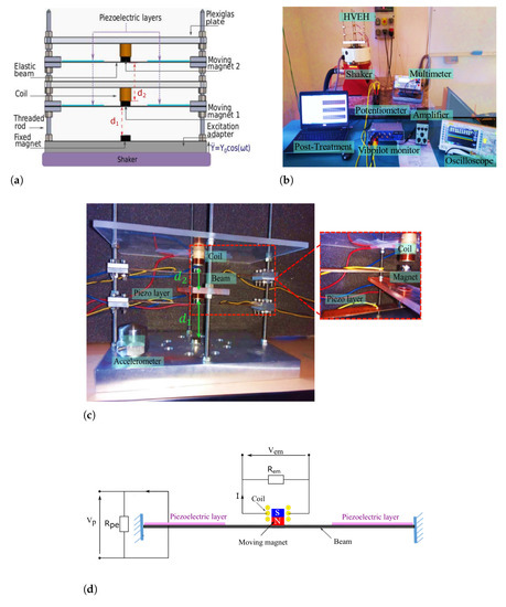
Figure 1.
(a) The proposed hybrid energy harvester destined to activate the internal resonance phenomenon; (b) the experimental setup; (c) the proposed hybrid vibration energy harvester (HVEH); (d) circuit of the tested piezoelectric and electromagnetic voltages of the hybrid energy harvesting system.

Table 1.
Characteristics of the used coils and magnets.
Table 2.
Design parameters of the piezoelectric patches.
In order to obtain the governing equations of the nonlinear harvester, the fourth order partial differential equations of the continuum multiphysics system are derived using the Hamilton principle. Then, a reduced-order model is generated by the Galerkin method, transforming the continuum system into a finite-degree-of-freedom one in terms of generalized coordinates [35]. Considering as the vibration amplitude of the magnet i , as the output voltage of the PE element and as the output current of the EM element (Figure 1d), the governing multi-physics equations of the nonlinear 2DOFs system can be written as follows:
where m is the mass of the identical magnets , are the generalized coordinates of the DOFs; is the damping coefficient; is the linear mechanical stiffness. refers to the nonlinear magnetic repulsive force between magnets and to the acceleration of the basis excitation. and stand for the resistances of the PE and EM elements, respectively, and is the coil internal resistance. is the equivalent capacitance of the PE element; is the PE element transfer factor, and is the electromagnetic coefficient.
It is noted that the electric output of the EM element (Figure 1d) can be obtained through this equation , where the displacement is calculated numerically by solving the equations obtained by the multiple scales method detailed in the Appendix A.
The magnetic force applied to each magnet can be written as follows: [54]
where is the gap between the magnets and , is the magnetic intensity of the identical magnets, and refers to the permeability of free space.
By expanding Equation (2) in Taylor series up to the third order [35], the equations of motion of the system in Equation (1) can be written in the following form:
where is the normalized damping, and are the mechanical and electrical damping coefficients, respectively, is the eigenfrequency of the first decoupled DOF; and are are the coupling coefficient related to the bottom and top magnets, respectively, and are the linear magnetic stiffness related to the bottom and top magnets, respectively. , , and are terms derived from the expansion of . and are terms derived from the expansion of . is the normalized transfer factor. It is noted that the quadratic terms give rise to the activation of the IR phenomenon, and the cubic ones are responsible of the softening or hardening behaviors according to the signs.
The influence of electrical networks on mechanics and vice versa is studied. The load resistance is inversely proportional to the electrical damping. Therefore, in the neighborhood of the eigenfrequency, each increase of the load resistance will cause the increase of the vibration amplitude. Indeed, the increase of , and in the load resistance (of the PE element for example) results in a , and increase of the amplitude of vibration, respectively. It can be seen that the resistive loads affect the harvester dynamics. Inversely, a change of , and of the second frequency induces a change of , and in the output voltage. This also shows that the mechanical parameter affects the electrical output.
The linear natural frequencies and of the 2DOFs harvester for undamped free vibrations are such that
Based on Equation (4), it is shown that the natural frequencies of the system can be tuned while tuning the linear magnetic force, which is a function of the separation distance between the magnets defined by the gaps and . By tuning the distance between the two magnets, the relationship between the first and second natural frequencies becomes commensurable with different ratios. It has been shown that 1:1 IR, which corresponds to a nonlinear mode-localized configuration [55], is possible for mm and mm. Moreover, as shown in Figure 2a, the separation distances and can be adjusted so that a modal interaction of 2:1 ratio is achieved and thus 2:1 internal resonance occurs. Henceforward, we define and as the well-chosen gaps. Setting mm, the required distance , satisfying that the second modal frequency of the structure is nearly twice its first modal frequency, is equal to mm.
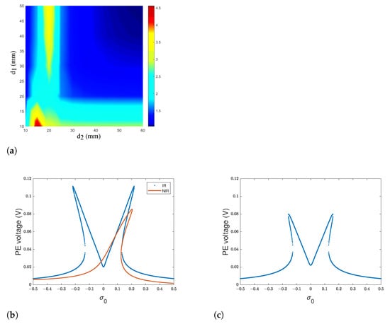
Figure 2.
(a) Ratio of the natural frequency to while varying the gaps and (b) piezoelectric voltage response curve around the primary resonance for an Internally Resonant (IR) harvester and case of a Non-Internally-Resonant (NIR) harvester; (c) voltage response curve around the primary resonance for IR harvester.
3. Results and Discussion
In order to investigate the benefits of the internal resonance on the harvester performances, an analytical study was conducted where the method of multiple scales (MMS) [43] is used to solve the coupled differential equations. Some terms of Equation (3) do not significantly affect the response of the harvester and are, therefore, dropped. The resolution procedure of the equations is developed in the Appendix A. The first primary resonance is described by the following relations , where is the excitation frequency, and are detuning parameters to describe the nearness of to and to , respectively and is a scaling parameter. Similarly, the second primary resonance is described by the following relations .
While fixing the well-chosen values of the gaps and , two peaks having almost the same amplitude appear around the first and the second natural frequencies as depicted in Figure 2b,c, respectively. The voltage response curves comparison for the cases with and without the 2:1 frequency tuning is illustrated in Figure 2b. The nonlinear response away from internal resonance (NIR) is obtained for gaps equal to 50 mm. While the frequency response with functionalization of the IR phenomenon bends to the left and to the right around the central frequency, the case without tuning presents a single peak. The existing of two bending branches bending to opposite directions of the central frequency of 92 Hz results in a significant increase in the amplitude and a broadening in the bandwidth. In fact, an enhancement of in voltage amplitude is demonstrated. Moreover, the frequency bandwidth is increased by , which corresponds to a frequency range of 13 Hz.
In order to highlight these effects, experimental tests have been realized. To do that, the HVEH was fabricated, and the experimental test bench was set as shown in Figure 1b,c, respectively. The power of nonlinear energy harvesting is evaluated according to for different load resistance at the base excitation level of , where is either or according to the conversion mechanism. The piezoelectric patches and the coils are connected separately. Each component is connected to a separate load resistance. Throughout the experiments, the voltage frequency responses are recorded in terms of the root-mean-square (RMS) value. Up and down sweeps are performed during the experiments to capture the bifurcation points of the nonlinear frequency response for a base acceleration of . As depicted in Figure 3a,b, it is shown that the PE load resistance does not affect the EM voltage. However, the variation in EM load resistance significantly changes the amplitude of the harvesting system and thus the voltage and the power of the PE element. By varying the load resistances, the EM and PE optimal resistances maximizing the total PE and EM powers are obtained at and , respectively, as illustrated in Figure 3c,d. The power density of the EM elements for is and the one of the PE elements for is . The optimal load resistances ( and ) as well as the well-chosen gap are fixed. For reasons of the experiments tolerance, is fixed to mm. Therefore, experimental tests have been performed to determine the nonlinear dynamic behavior of the hybrid harvester. Under these conditions, the second natural frequency is of 185 Hz and is equal to twice the first natural one Hz according to Equation (4). As shown in Figure 4a, the obtained value of the first natural frequency is experimentally validated. Through experiments, it has been shown that, for Hz giving a ratio , the internal resonance phenomenon is activated. In fact, the response curves show the existence of an additional peak that appears around the frequency of the first mode (92.5 Hz) of the bottom DOF where hardening and softening responses are simultaneously observed.
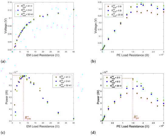
Figure 3.
(a) Voltage of the bottom EM elements versus the PE load resistances; (b) voltage of the PE elements versus the EM load resistances; (c) harvested power from the EM elements; (d) harvesting power from the PE elements.
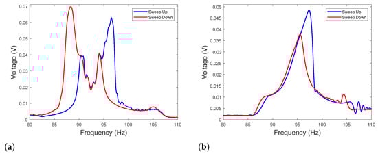
Figure 4.
(a) Frequency response with optimal parameters ensuring the activation of the internal resonance phenomenon ( mm and mm) around the resonance frequency (IR case) ; (b) frequency response away from internal resonance condition ( mm and mm) around the resonance frequency (NIR case) .
To highlight the importance of the internal resonance phenomenon toward the output performance of the harvester, a configuration away from internal resonance is studied. Based on Equation (4) and Figure 2a, the distances and are fixed both to 50 mm such that .
Figure 4b shows the output power of the hybrid energy harvester away from the 2:1 internal resonance condition. Only softening nonlinearity is demonstrated. It is observed that the activation of the internal resonance results in increasing both the power density and the frequency bandwidth. An enhancement of of power density is achieved compared to the generator away from the 2:1 internal resonance. Considering this result, it is shown that, for well-chosen gaps resulting in 2:1 internal resonance, it is possible to reduce the volume of the harvester by almost two times by adjusting the gaps and achieve increase in the harvested power. By specifying the internal resonance frequency bandwidth by the half-power bandwidth method in the frequency range that corresponds to the two upward peaks (87 Hz–98 Hz), it is also shown that the internal resonance widens the frequency bandwidth by comparing to the case away from 2:1 internal resonance.
In order to compare the harvester performance to the existing ones, a Systematic Figure of Merit (SFoM) proposed by [56] is used. This SFoM is an effective performance evaluation and design directive tool. It takes into consideration the power density and the frequency bandwidth as follows:
where is the average power, is the frequency bandwidth, a is the acceleration (g unit), and is the effective volume of the harvester.
According to this figure of merit, the performance of the current work harvester and the ones of other harvesters are illustrated in Figure 5. It can be seen that the proposed harvester provides competitive performance compared to the existing vibration energy harvesters.
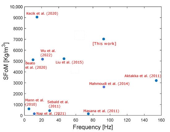
Figure 5.
Comparison of the proposed harvester SFoM with the current state-of-the-art [35,56,57,58,59,60,61,62,63,64].
The harvested energy from the hybrid structure needs to be stored to power small consumption devices. As the harvester output signals are alternating (AC), they need to be transformed to direct ones (DC) before being stored. Accordingly, an energy storage circuit including the rectifier, the filter, and the signal regulator is designed. The energy acquisition and storage circuit diagram are depicted in Figure 6a. This storage test is a proof of charging. For that, we have chosen, at present, to store the output of one PE element (the right patch clamped to the bottom beam). The outputs are connected to an electronic module to rectify, filter, and then regulate the signals. The practical value of the diodes threshold voltage is of 0.2 V. After being regulated, the electrical harvested voltage is stored in capacitor. In the experiment, the voltage is recorded by an acquisition card when the harvester is vibrating. As seen in Figure 6b, the maximum voltage obtained is of 0.44 V. The evolution with time on this load capacitor in the charging and discharging phases is illustrated in Figure 6c. The maximum voltage across the capacitor is of 0.38 V. It is shown that the stored battery voltage rises from 0.02 V up to 0.33 V in 1 min under a basis excitation of 0.7 g.
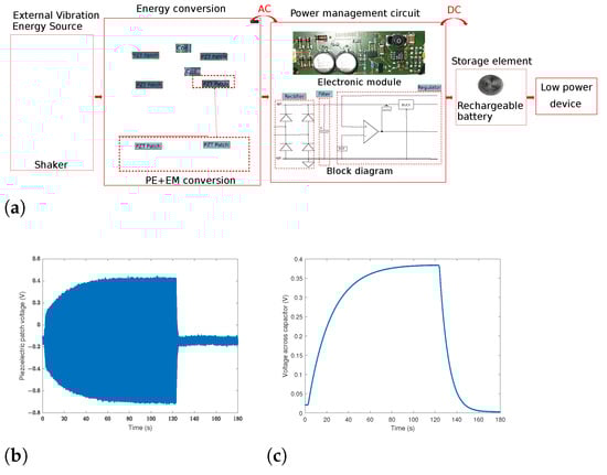
Figure 6.
(a) Energy acquisition and storage circuit diagram of the HVEH output harvested electrical energy; (b) voltage of the piezoelectric patch; (c) voltage across a 100 F capacitor.
The results of this study have to be seen in light of some limitations. The first is the storage of the output energy of the PE and EM elements. In this article, the energy is stored from the output of one PE element. An adaptation of the EM and PE elements’ outputs should be conducted in order to be able to store the two outputs in the same storage device. The second one concerns the miniaturization of the system, which is limited because of the constraints related to magnet downscaling. Consequently, other technologies should be proposed to replace the magnetic coupling, namely the elastic coupling using an elastic beam [65]. The third limitation consists of the type of excitation. In fact, this study is based on the harmonic excitation. However, for a more practically available ambient source, the vibration energy should be harvested when the structure is subjected to random excitation.
4. Conclusions
In conclusion, the functionalization and the tuning of the phenomenon of internal resonance are demonstrated in this paper. This results in a significant enhancement of the frequency bandwidth and the harvested power of the nonlinear hybrid piezoelectric-electromagnetic harvester. A prototype of this 2DOF harvester is designed with well-chosen parameters of the PE and EM transductions. These design parameters can be improved by performing a parametric optimization procedure [32,66,67]. By adjusting the gaps between the magnets, the magnetic forces are varied and consequently the natural frequencies of the harvester are tuned so that they are commensurate. Both analytical simulations and experiments capture the nonlinear behavior of the internal resonance phenomenon. It is proved that the activation of the nonlinearity facilitates a nonlinear energy exchange between the commensurate modes. In fact, the existence of two peaks around the first and the second primary resonance results in a wider bandwidth and a larger output. Indeed, it has been demonstrated that, for well-chosen gaps resulting in 2:1 IR, an increase of in the harvested power and an enlargement of in the bandwidth are achieved. For these parameters, the harvester’s volume is reduced by nearly two times compared to the configuration away from IR. A storage test as a proof of charging has been done using a 100 F capacitor. It has been shown that the voltage raises from 0.02 V to 0.33 V in one minute. This storage test has been realized on the PE element output. Future work will focus on the storage from both the PE and EM elements and will include the extension of the proposed concept to very large scale integrated harvesters based on coupled nonlinear resonators with simultaneous resonances [68].
Author Contributions
Conceptualization, K.A., N.K. and N.B.; Data curation, K.A., N.K. and N.B.; Formal analysis, K.A., N.K. and N.B.; Funding acquisition, N.K. and N.B.; Investigation, K.A., N.K. and N.B.; Methodology, K.A., N.K. and N.B.; Project administration, N.K. and N.B.; Resources, N.K. and N.B.; Software, K.A.; Supervision, N.K. and N.B.; Validation, K.A., N.K. and N.B.; Writing—original draft, K.A.; Writing—review and editing, K.A., N.K. and N.B. All authors have read and agreed to the published version of the manuscript.
Funding
This research was funded by the EUR EIPHI program (ANR 17-EURE-0002).
Institutional Review Board Statement
Not applicable.
Informed Consent Statement
Not applicable.
Data Availability Statement
The data that support the findings of this study are available within the article.
Conflicts of Interest
The authors declare no conflict of interest.
Appendix A. Resolution Procedure with the Method of Multiple Scales (MMS)
Dropping the terms which do not have a significant effect on the system frequency response, Equation (3) becomes equivalent to:
In order to implement the MMS on Equation (A1), we introduce the following time scales where and is a scaling parameter. We define .
The scaled equations around the first primary resonance can be written as follows:
Considering , the solution of Equation (A1) in the function of the new scales can be represented by an expansion having the following form:
Substituting Equation (A3) into Equation (A2) and equating coefficients into orders of , the terms of order 0 give the following differential equations:
The terms of order 1 are written as follows:
In addition, the equations of order 2 are expressed as follows:
We introduce the detuning parameter to describe the nearness of to and the detuning parameter to describe the nearness of to . Consequently, the first primary resonance with 2:1 IR is described by the following frequency relations:
The particular solution of Equation (A5) can be written as follows:
Let and be the amplitudes of the solutions of Equation (A4). Consequently, the solution of Equation (A5) can be written as:
We substitute Equation (A9) into Equation (A6) and eliminate the terms that produce secular terms; then, we collect the terms proportional to and . We obtain the following equations:
We propose the following polar transformation:
We integrate Equation (A11) into Equation (A10) and differentiate the real and the imaginary parts. Then, we propose the following change of variable:
In order to obtain the steady state response, we set and .
Considering this yields the following system:
Solving Equation (A13) gives the amplitude response by varying in Equation (A7) setting to a very small value.
Around the second resonance frequency, the scaled equations can be written as follows:
Following the same steps as the resolution of the first primary resonance, we describe the 2:1 IR by the following relations around the second frequency:
The change of variable that is used in this case is as follows:
Then, we obtain the following corresponding amplitude modulation equations around the second primary resonance:
References
- Roundy, S.; Wright, P.K. A piezoelectric vibration based generator for wireless electronics. Smart Mater. Struct. 2004, 13, 1131–1142. [Google Scholar] [CrossRef]
- Tang, L.; Yang, Y.; Soh, C.K. Toward broadband vibration-based energy harvesting. J. Intell. Mater. Syst. Struct. 2010, 21, 1867–1897. [Google Scholar] [CrossRef]
- Zhu, D.; Tudor, M.J.; Beeby, S. Strategies for increasing the operating frequency range of vibration energy harvesters: A review. Meas. Sci. Technol. 2009, 21, 022001. [Google Scholar] [CrossRef]
- Twiefel, J.; Westermann, H. Survey on broadband techniques for vibration energy harvesting. J. Intell. Mater. Syst. Struct. 2013, 24, 1291–1302. [Google Scholar] [CrossRef]
- Ibrahim, S.W.; Ali, W.G. A review on frequency tuning methods for piezoelectric energy harvesting systems. J. Renew. Sustain. Energy 2012, 4, 062703. [Google Scholar] [CrossRef]
- Hu, Y.; Xue, H.; Hu, H. A piezoelectric power harvester with adjustable frequency through axial preloads. Smart Mater. Struct. 2007, 16, 1961–1966. [Google Scholar] [CrossRef]
- Eichhorn, C.; Goldschmidtboeing, F.; Woias, P. A frequency tunable piezoelectric energy converter based on a cantilever beam. Proc. PowerMEMS 2008, 9, 309–312. [Google Scholar]
- Morris, D.J.; Youngsman, J.M.; Anderson, M.J.; Bahr, D. A resonant frequency tunable, extensional mode piezoelectric vibration harvesting mechanism. Smart Mater. Struct. 2008, 17, 065021. [Google Scholar] [CrossRef]
- Loverich, J.; Geiger, R.; Frank, J. Stiffness nonlinearity as a means for resonance frequency tuning and enhancing mechanical robustness of vibration power harvesters. In Active and Passive Smart Structures and Integrated Systems; International Society for Optics and Photonics: Bellingham, WA, USA, 2008; Volume 6928. [Google Scholar]
- Karadag, C.V.; Topaloglu, N. A Self-Sufficient and Frequency Tunable Piezoelectric Vibration Energy Harvester. J. Vib. Acoust. 2016, 139, 011013. [Google Scholar] [CrossRef]
- Hsu, J.-C.; Tseng, C.-T.; Chen, Y.-S. Analysis and experiment of self-frequency-tuning piezoelectric energy harvesters for rotational motion. Smart Mater. Struct. 2014, 23, 075013. [Google Scholar] [CrossRef]
- Priya, S.; Inman, D.J. (Eds.) Energy Harvesting Technologies; Springer: New York, NY, USA, 2009; Volume 21. [Google Scholar]
- Tadesse, Y.; Zhang, S.; Priya, S. Multimodal Energy Harvesting System: Piezoelectric and Electromagnetic. J. Intell. Mater. Syst. Struct. 2008, 20, 625–632. [Google Scholar] [CrossRef]
- Ahmad, M.M.; Khan, N.M.; Khan, F.U. Multi-degrees of freedom energy harvesting for broad-band vibration frequency range: A review. Sens. Actuators A Phys. 2022, 344, 113690. [Google Scholar] [CrossRef]
- Huang, X.; Zhang, C.; Dai, K. A Multi-Mode Broadband Vibration Energy Harvester Composed of Symmetrically Distributed U-Shaped Cantilever Beams. Micromachines 2021, 12, 203. [Google Scholar] [CrossRef] [PubMed]
- Thong, L.W.; Kok, S.L.; Ramlan, R. Modeling of Multiple Cantilevers System for Broadband Vibration Energy Harvester. In Proceedings of the 2021 4th International Seminar on Research of Information Technology and Intelligent Systems (ISRITI), Yogyakarta, Indonesia, 16–17 December 2021. [Google Scholar]
- Nabavi, S.; Zhang, L. Nonlinear Multi-Mode Wideband Piezoelectric MEMS Vibration Energy Harvester. IEEE Sens. J. 2019, 19, 4837–4848. [Google Scholar] [CrossRef]
- Shahruz, S. Design of mechanical band-pass filters for energy scavenging. J. Sound Vib. 2006, 292, 987–998. [Google Scholar] [CrossRef]
- Oyabur, R.; Salauddin, M.; Cho, H.; Park, J.Y. A multimodal hybrid energy harvester based on piezoelectric-electromagnetic mechanisms for low-frequency ambient vibrations. Energy Convers. Manag. 2018, 168, 454–466. [Google Scholar]
- Yang, B.; Lee, C.; Xiang, W.; Xie, J.; He, J.H.; Kotlanka, R.K.; Low, S.P.; Feng, H. Electromagnetic energy harvesting from vibrations of multiple frequencies. J. Micromech. Microeng. 2009, 19, 035001. [Google Scholar] [CrossRef]
- Roundy, S.; Leland, E.S.; Baker, J.; Carleton, E.; Reilly, E.; Lai, E.; Otis, B.; Rabaey, J.M.; Wright, P.K.; Sundararajan, V. Improving Power Output for Vibration-Based Energy Scavengers. IEEE Pervasive Comput. 2005, 4, 28–36. [Google Scholar] [CrossRef]
- Qin, H.; Mo, S.; Jiang, X.; Shang, S.; Wang, P.; Liu, Y. Multimodal Multidirectional Piezoelectric Vibration Energy Harvester by U-Shaped Structure with Cross-Connected Beams. Micromachines 2022, 13, 396. [Google Scholar] [CrossRef]
- Eshtehardiha, R.; Tikani, R.; Ziaei-Rad, S. Experimental and numerical investigation of energy harvesting from double cantilever beams with internal resonance. J. Sound Vib. 2021, 500, 116022. [Google Scholar] [CrossRef]
- Yu, N.; Ma, H.; Wu, C.; Yu, G.; Yan, B. Modeling and experimental investigation of a novel bistable two-degree-of-freedom electromagnetic energy harvester. Mech. Syst. Signal Process. 2021, 156, 107608. [Google Scholar] [CrossRef]
- Jia, Y. Review of nonlinear vibration energy harvesting: Duffing, bistability, parametric, stochastic and others. J. Intell. Mater. Syst. Struct. 2020, 31, 921–944. [Google Scholar] [CrossRef]
- Jia, Y.; Du, S.; Arroyo, E.; Seshia, A.A. Autoparametric resonance in a piezoelectric MEMS vibration energy harvester. In Proceedings of the IEEE Micro Electro Mechanical Systems (MEMS), Belfast, UK, 21–25 January 2018. [Google Scholar]
- Maamer, B.; Boughamoura, A.; El-Bab, A.M.F.; Francis, L.A.; Tounsi, F. A review on design improvements and techniques for mechanical energy harvesting using piezoelectric and electromagnetic schemes. Energy Convers. Manag. 2019, 199, 111973. [Google Scholar] [CrossRef]
- Amri, M.; Basset, P.; Cottone, F.; Galayko, D.; Najar, F. Novel nonlinear spring design for wideband vibration energy harvesters. In Proceedings of the 11th International Workshop on Micro and Nanotechnology for Power Generation and Energy Conversion Applications, PowerMEMS 2011, Seoul, Korea, 15–18 November 2011. [Google Scholar]
- Engel, E.; Wei, J.; Lee, C.L. Enhanced vibration energy harvesting using nonlinear oscillations. In Energy Harvesting and Storage: Materials, Devices, and Applications; International Society for Optics and Photonics: Bellingham, WA, USA, 2015; Volume 9493. [Google Scholar]
- Mann, B.; Sims, N. Energy harvesting from the nonlinear oscillations of magnetic levitation. J. Sound Vib. 2009, 319, 515–530. [Google Scholar] [CrossRef]
- Sathyamoorthy, M. Nonlinear Vibrations of Plates: An Update of Recent Research Developments. Appl. Mech. Rev. 1996, 49, S55–S62. [Google Scholar] [CrossRef]
- Abed, I.; Kacem, N.; Bouhaddi, N.; Bouazizi, M.L. Multi-modal vibration energy harvesting approach based on nonlinear oscillator arrays under magnetic levitation. Smart Mater. Struct. 2016, 25, 025018. [Google Scholar] [CrossRef]
- Drezet, C.; Kacem, N.; Bouhaddi, N. Design of a nonlinear energy harvester based on high static low dynamic stiffness for low frequency random vibrations. Sens. Actuators A Phys. 2018, 283, 54–64. [Google Scholar] [CrossRef]
- Lyu, M.; Zhao, J.; Kacem, N.; Liu, P.; Tang, B.; Xiong, Z.; Wang, H.; Huang, Y. Exploiting nonlinearity to enhance the sensitivity of mode-localized mass sensor based on electrostatically coupled MEMS resonators. Int. J. Non-Linear Mech. 2020, 121, 103455. [Google Scholar] [CrossRef]
- Mahmoudi, S.; Kacem, N.; Bouhaddi, N. Enhancement of the performance of a hybrid nonlinear vibration energy harvester based on piezoelectric and electromagnetic transductions. Smart Mater. Struct. 2014, 23, 075024. [Google Scholar] [CrossRef]
- Liu, H.; Koh, K.H.; Lee, C.; Liu, H.; Koh, K.H.; Lee, C. Ultra-wide frequency broadening mechanism for micro-scale electromagnetic energy harvester. Appl. Phys. Lett. 2014, 104, 053901. [Google Scholar] [CrossRef]
- Stanton, S.C.; McGehee, C.C.; Mann, B.P. Nonlinear dynamics for broadband energy harvesting: Investigation of a bistable piezoelectric inertial generator. Phys. D Nonlinear Phenom. 2010, 239, 640–653. [Google Scholar] [CrossRef]
- Sebald, G.; Kuwano, H.; Guyomar, D.; Ducharne, B. Experimental Duffing oscillator for broadband piezoelectric energy harvesting. Smart Mater. Struct. 2011, 20, 102001. [Google Scholar] [CrossRef]
- Wu, Y.; Li, S.; Fan, K.; Ji, H.; Qiu, J. Investigation of an ultra-low frequency piezoelectric energy harvester with high frequency up-conversion factor caused by internal resonance mechanism. Mech. Syst. Signal Process. 2021, 162, 108038. [Google Scholar] [CrossRef]
- Chen, L.-Q.; Jiang, W.-A. Internal Resonance Energy Harvesting. J. Appl. Mech. 2015, 82, 031004. [Google Scholar] [CrossRef]
- Cao, D.; Leadenham, S.; Erturk, A. Internal resonance for nonlinear vibration energy harvesting. Eur. Phys. J. Spec. Top. 2015, 224, 2867–2880. [Google Scholar] [CrossRef]
- Jiang, W.-A.; Ma, X.-D.; Han, X.-J.; Chen, L.-Q.; Bi, Q.-S. Broadband energy harvesting based on one-to-one internal resonance. Chin. Phys. B 2020, 29, 100503. [Google Scholar] [CrossRef]
- Nayfeh, A.H.; Mook, D.T. Nonlinear Oscillations; John Wiley & Sons: Hoboken, NJ, USA, 2008. [Google Scholar]
- Nie, X.; Tan, T.; Yan, Z.; Yan, Z.; Hajj, M.R. Broadband and high-efficient L-shaped piezoelectric energy harvester based on internal resonance. Int. J. Mech. Sci. 2019, 159, 287–305. [Google Scholar] [CrossRef]
- Rocha, R.T.; Balthazar, J.M.; Tusset, A.M.; Piccirillo, V.; Felix, J.L.P. Nonlinear piezoelectric vibration energy harvesting from a portal frame with two-to-one internal resonance. Meccanica 2017, 52, 2583–2602. [Google Scholar] [CrossRef]
- Hou, S.; Teng, Y.-Y.; Zhang, Y.-W.; Zang, J. Enhanced Energy Harvesting of a Nonlinear Energy Sink by Internal Resonance. Int. J. Appl. Mech. 2019, 11, 1950100. [Google Scholar] [CrossRef]
- Xu, C.; Zhao, L. Investigation on the characteristics of a novel internal resonance galloping oscillator for concurrent aeroelastic and base vibratory energy harvesting. Mech. Syst. Signal Process. 2022, 173, 109022. [Google Scholar] [CrossRef]
- Yang, W.; Towfighian, S. A hybrid nonlinear vibration energy harvester. Mech. Syst. Signal Process. 2017, 90, 317–333. [Google Scholar] [CrossRef]
- Xiong, L.; Tang, L.; Mace, B.R. Internal resonance with commensurability induced by an auxiliary oscillator for broadband energy harvesting. Appl. Phys. Lett. 2016, 108, 203901. [Google Scholar] [CrossRef]
- Liu, W.; Badel, A.; Formosa, F.; Wu, Y.; Bencheikh, N.; Agbossou, A. A wideband integrated piezoelectric bistable generator: Experimental performance evaluation and potential for real environmental vibrations. J. Intell. Mater. Syst. Struct. 2014, 26, 872–877. [Google Scholar] [CrossRef]
- Xiong, L.; Tang, L.; Mace, B.R. A comprehensive study of 2:1 internal-resonance-based piezoelectric vibration energy harvesting. Nonlinear Dyn. 2017, 91, 1817–1834. [Google Scholar] [CrossRef]
- Yang, W.; Towfighian, S. Internal resonance and low frequency vibration energy harvesting. Smart Mater. Struct. 2017, 26, 095008. [Google Scholar] [CrossRef]
- Chen, L.-Q.; Jiang, W.-A.; Panyam, M.; Daqaq, M.F. A Broadband Internally Resonant Vibratory Energy Harvester. J. Vib. Acoust. 2016, 138, 061007. [Google Scholar] [CrossRef]
- Foisal, A.R.; Hong, C.; Chung, G.-S. Multi-frequency electromagnetic energy harvester using a magnetic spring cantilever. Sens. Actuators A Phys. 2012, 182, 106–113. [Google Scholar] [CrossRef]
- Aouali, K.; Kacem, N.; Bouhaddi, N.; Mrabet, E.; Haddar, M. Efficient broadband vibration energy harvesting based on tuned nonlinearity and energy localization. Smart Mater. Struct. 2020, 29, 10LT01. [Google Scholar] [CrossRef]
- Liu, W.; Badel, A.; Formosa, F.; Wu, Y.P. A new figure of merit for wideband vibration energy harvesters. Smart Mater. Struct. 2015, 24, 125012. [Google Scholar] [CrossRef]
- Sebald, G.; Kuwano, H.; Guyomar, D.; Ducharne, B. Simulation of a Duffing oscillator for broadband piezoelectric energy harvesting. Smart Mater. Struct. 2011, 20, 075022. [Google Scholar] [CrossRef]
- Masana, R.; Daqaq, M.F. Relative performance of a vibratory energy harvester in mono- and bi-stable potentials. J. Sound Vib. 2011, 330, 6036–6052. [Google Scholar] [CrossRef]
- Mann, B.; Owens, B. Investigations of a nonlinear energy harvester with a bistable potential well. J. Sound Vib. 2010, 329, 1215–1226. [Google Scholar] [CrossRef]
- Aktakka, E.E.; Peterson, R.L.; Najafi, K. Thinned-PZT on SOI process and design optimization for piezoelectric inertial energy harvesting. In Proceedings of the 2011 16th International Solid-State Sensors, Actuators and Microsystems Conference, Beijing, China, 5–9 June 2011. [Google Scholar]
- Beato-López, J.J.; Royo-Silvestre, I.; Algueta-Miguel, J.M.; Gómez-Polo, C. A Combination of a Vibrational Electromagnetic Energy Harvester and a Giant Magnetoimpedance (GMI) Sensor. Sensors 2020, 20, 1873. [Google Scholar] [CrossRef]
- Kecik, K.; Mitura, A. Theoretical and Experimental Investigations of a Pseudo-Magnetic Levitation System for Energy Harvesting. Sensors 2020, 20, 1623. [Google Scholar] [CrossRef]
- Wu, Z.; Xu, Q. Design of a structure-based bistable piezoelectric energy harvester for scavenging vibration energy in gravity direction. Mech. Syst. Signal Process. 2022, 162, 108043. [Google Scholar] [CrossRef]
- Nan, W.; He, Y.; Fu, J. Bistable energy harvester using easy snap-through performance to increase output power. Energy 2021, 226, 120414. [Google Scholar] [CrossRef]
- Rabenimanana, T.; Walter, V.; Kacem, N.; Le Moal, P.; Bourbon, G.; Lardiès, J. Functionalization of electrostatic nonlinearities to overcome mode aliasing limitations in the sensitivity of mass microsensors based on energy localization. Appl. Phys. Lett. 2020, 117, 033502. [Google Scholar] [CrossRef]
- Majak, J.; Pohlak, M. Decomposition method for solving optimal material orientation problems. Compos. Struct. 2010, 92, 1839–1845. [Google Scholar] [CrossRef]
- Nabavi, S.; Zhang, L. Design and Optimization of a Low-Resonant-Frequency Piezoelectric MEMS Energy Harvester Based on Artificial Intelligence. Multidiscip. Digit. Publ. Inst. Proc. 2018, 2, 930. [Google Scholar]
- Jallouli, A.; Kacem, N.; Bouhaddi, N. Stabilization of solitons in coupled nonlinear pendulums with simultaneous external and parametric excitations. Commun. Nonlinear Sci. Numer. Simul. 2017, 42, 1–11. [Google Scholar] [CrossRef]
Publisher’s Note: MDPI stays neutral with regard to jurisdictional claims in published maps and institutional affiliations. |
© 2022 by the authors. Licensee MDPI, Basel, Switzerland. This article is an open access article distributed under the terms and conditions of the Creative Commons Attribution (CC BY) license (https://creativecommons.org/licenses/by/4.0/).