
Earable Ω (OMEGA): A Novel Clenching Interface Using Ear Canal Sensing for Human Metacarpophalangeal Joint Control by Functional Electrical Stimulation
 , and
, and
Abstract
1. Introduction
- (1)
- Trying to control MP joint angle by EAA ratio using earable ;
- (2)
- Trying to control MP joint stiffness by EAA sum using earable .
2. Materials and Methods
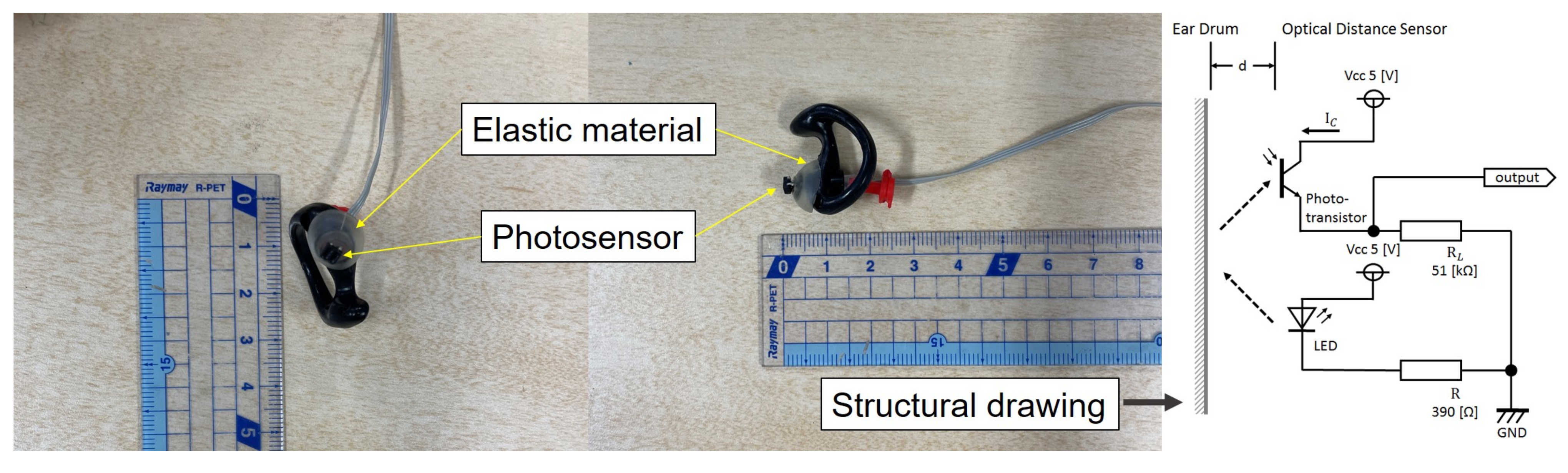
2.1. Earable
2.2. Experiment 1: Controlling Joint Angle Using Earable as an Interface
2.2.1. EAA Ratio and EAA Sum for Joint Angle Control
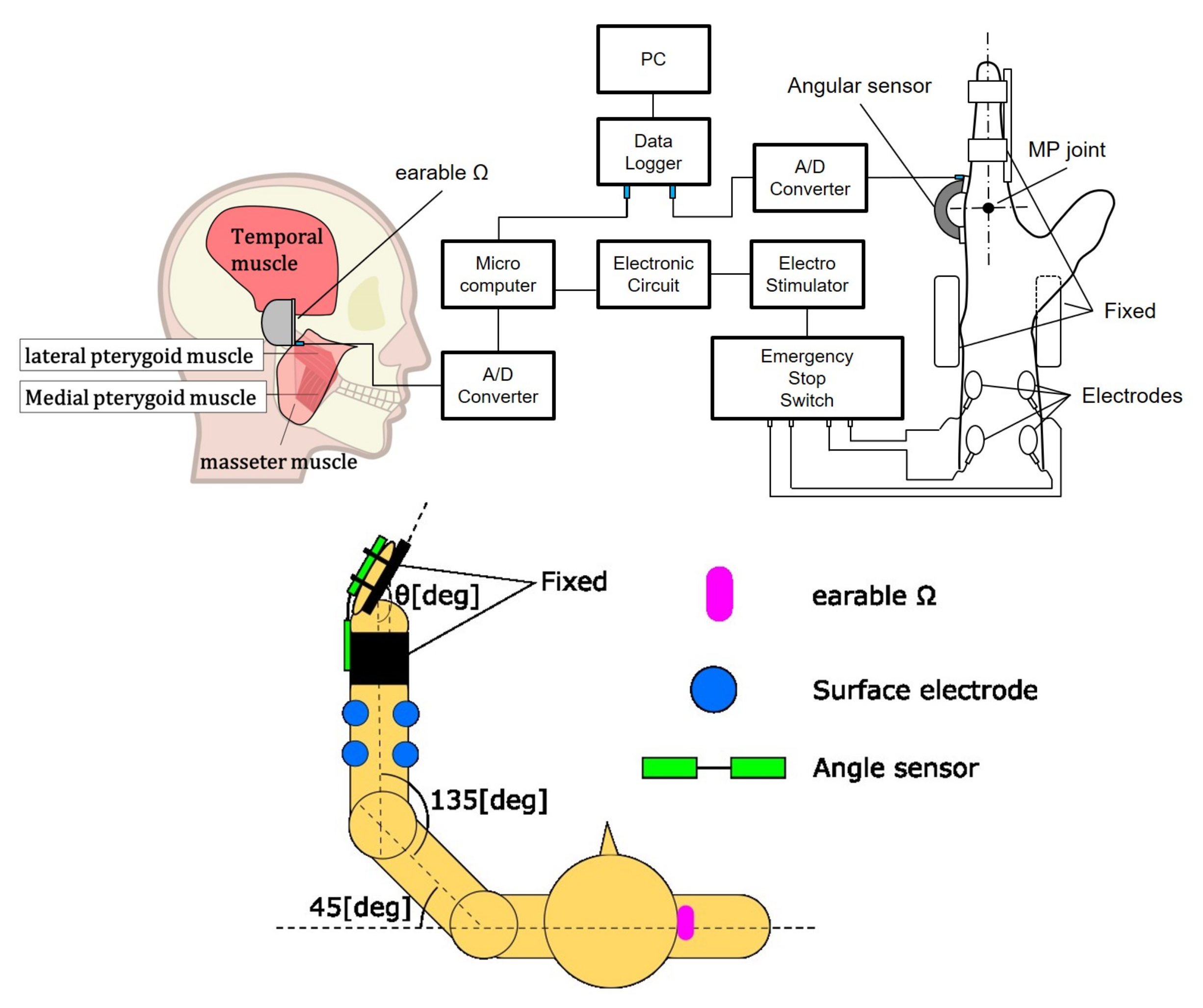
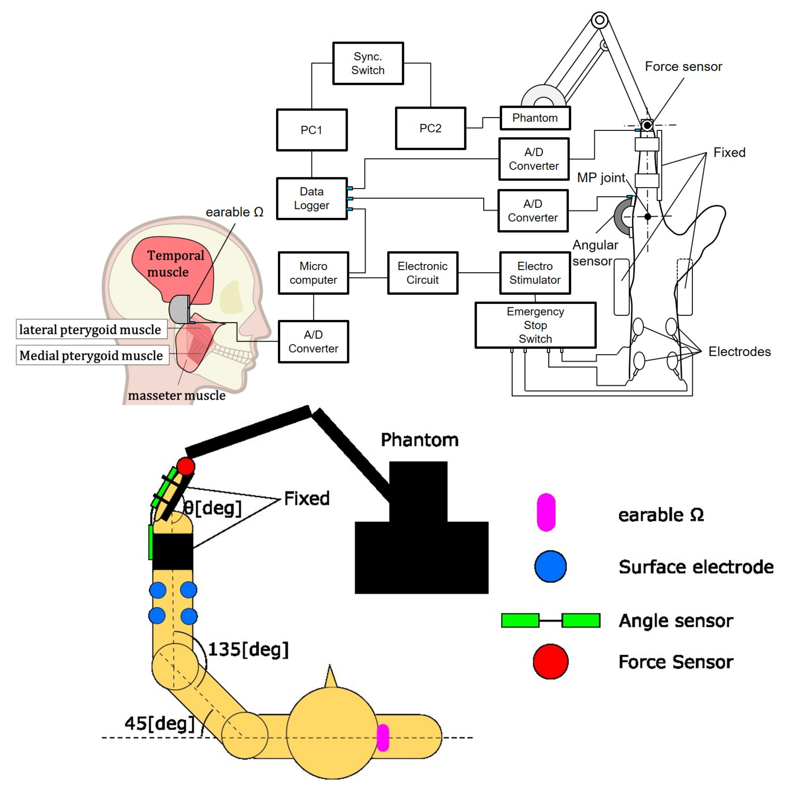
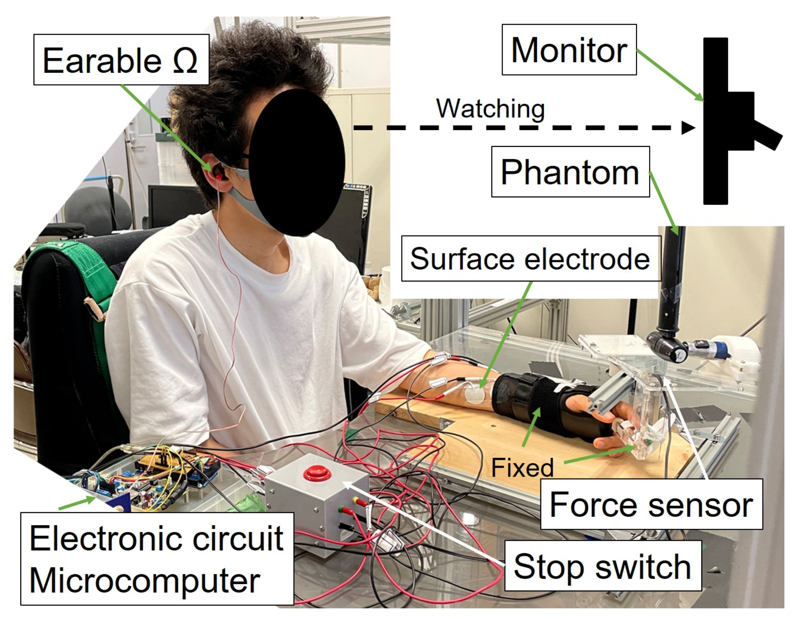
2.2.2. The Developed System for Experiment 1
2.2.3. Experimental Environment and Method
2.3. Experiment 2: Controlling Joint Stiffness Using Earable as an Interface
2.3.1. The Developed System for Experiment 2
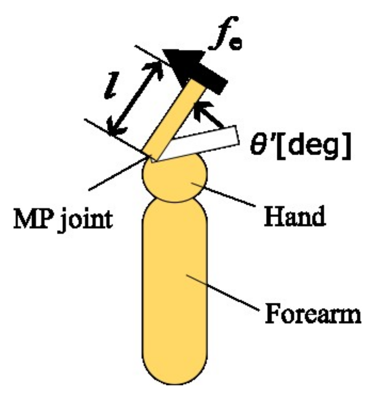
2.3.2. Acquirement of Joint Stiffness
2.3.3. Experimental Environment and Method
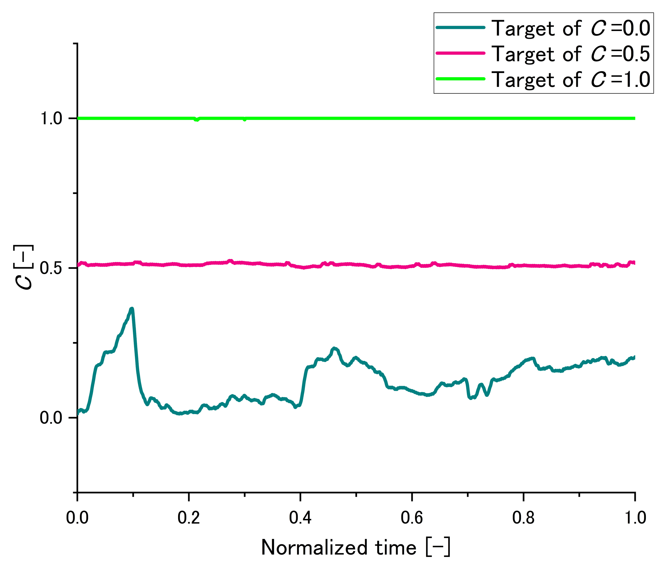
2.3.4. An Example of Maintaining C
2.3.5. Information on Subjects
3. Results
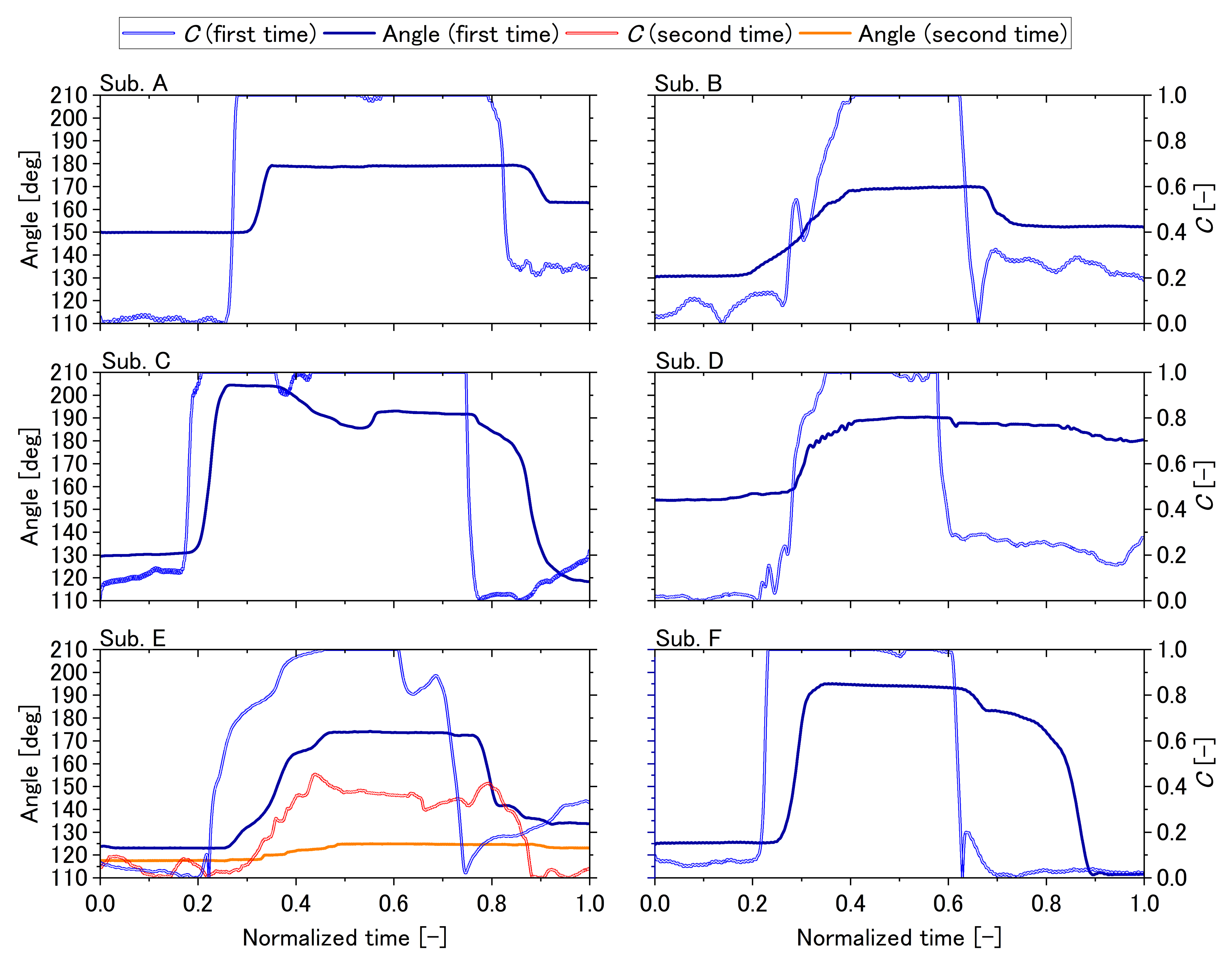
3.1. Experiment 1
3.2. Experiment 2
4. Discussion
4.1. Experiment 1
4.2. Experiment 2
4.3. Summary of Discussion
4.4. Future Outlook
5. Conclusions
Author Contributions
Funding
Institutional Review Board Statement
Informed Consent Statement
Data Availability Statement
Conflicts of Interest
References
- Mangold, S.; Keller, T.; Curt, A.; Dietz, V. Transcutaneous functional electrical stimulation for grasping in subjects with cervical spinal cord injury. Spinal Cord 2005, 43, 1–13. [Google Scholar] [CrossRef] [PubMed]
- Lynch, C.L.; Popovic, M.R. A comparison of closed-loop control algorithms for regulating electrically stimulated knee movements in individuals with spinal cord injury. IEEE Trans. Neural Syst. Rehabil. Eng. 2012, 20, 539–548. [Google Scholar] [CrossRef] [PubMed]
- Stites, E.C.; Abbas, J.J. Sensitivity and versatility of an adaptive system for controlling cyclic movements using functional neuromuscular stimulation. IEEE Trans. Biomed. Eng. 2000, 47, 1287–1292. [Google Scholar] [CrossRef] [PubMed]
- Popovic, M.R.; Curt, A.; Keller, T.; Dietz, V. Functional electrical stimulation for grasping and walking: Indications and limitations. Spinal Cord 2001, 39, 403–412. [Google Scholar] [CrossRef]
- Iannò, M.; Ferrarin, M.; Pedrocchi, A.; Ferrigno, G.; Capecelatro, V. A neuro-adaptive control system for knee joint movements during quadriceps electrical stimulation. In Proceedings of the 7th Annual Conference of the International Functional Electrical Stimulation Society, Ljubljana, Slovenia, 25–29 June 2002. [Google Scholar]
- Ferrarin, M.; Palazzo, F.; Riener, R.; Quintern, J. Model-based control of FES-induced single joint movements. IEEE Trans. Neural Syst. Rehabil. Eng. 2001, 9, 245–257. [Google Scholar] [CrossRef]
- Tu, X.; Han, H.; Huang, J.; Li, J.; Su, C.; Jiang, X.; He, J. Upper Limb Rehabilitation Robot Powered by PAMs Cooperates with FES Arrays to Realize Reach-to-Grasp Trainings. J. Healthc. Eng. 2017, 2017, 1282934. [Google Scholar] [CrossRef]
- Giuffrida, J.P.; Crago, P.E. Reciprocal EMG control of elbow extension by FES. IEEE Trans. Neural Syst. Rehabil. Eng. 2001, 9, 338–345. [Google Scholar] [CrossRef]
- Westerveld, A.J.; Kuck, A.; Schouten, A.C.; Veltink, P.H.; Van Der Kooij, H. Grasp and release with surface functional electrical stimulation using a Model Predictive Control approach. In Proceedings of the Annual International Conference of the IEEE Engineering in Medicine and Biology Society EMBS, San Diego, CA, USA, 28 August–1 September 2012; pp. 333–336. [Google Scholar] [CrossRef]
- Malešević, N.M.; Maneski, L.Z.; Ilić, V.; Jorgovanović, N.; Bijelić, G.; Keller, T.; Popović, D.B. A multi-pad electrode based functional electrical stimulation system for restoration of grasp. J. Neuroeng. Rehabil. 2012, 9, 66. [Google Scholar] [CrossRef]
- Watanabe, T.; Matsudaira, T.; Kurosawa, K.; Fujii, T.; Futami, R.; Hoshimiya, N.; Ichie, M. Wrist Joint Control by Multichannel Closed-loop FES System: System Improvement and First Clinical Test. In Proceedings of the 7th IFESS, Kuala Lumpur, Malaysia, 17–19 September 2002; pp. 265–267. [Google Scholar]
- Watanabe, T.; Iibuchi, K.; Kurosawa, K.; Hoshimiya, N. A method of multichannel PID control of two-degree-of-freedom wrist joint movements by functional electrical stimulation. Syst. Comput. Jpn. 2003, 34, 25–36. [Google Scholar] [CrossRef]
- Kurosawa, K.; Futami, R.; Watanabe, T.; Hoshimiya, N. Joint angle control by FES using a feedback error learning controller. IEEE Trans. Neural Syst. Rehabil. Eng. 2005, 13, 359–371. [Google Scholar] [CrossRef]
- Widjaja, F.; Shee, C.Y.; Au, W.L.; Poignet, P.; Ang, W.T. Using electromechanical delay for real-time anti-phase tremor attenuation system using functional electrical stimulation. In Proceedings of the IEEE International Conference on Robotics and Automation, Shanghai, China, 9–13 May 2011; pp. 3694–3699. [Google Scholar] [CrossRef]
- Adamczyk, M.M.; Crago, P.E. Simulated feedforward neural network coordination of hand grasp and wrist angle in a neuroprosthesis. IEEE Trans. Rehabil. Eng. 2000, 8, 297–304. [Google Scholar] [CrossRef]
- Matsui, K.; Hishii, Y.; Maegaki, K.; Yamashita, Y.; Uemura, M.; Hirai, H.; Miyazaki, F. Equilibrium-point control of human elbow-joint movement under isometric environment by using multichannel functional electrical stimulation. Front. Neurosci. 2014, 8, 164. [Google Scholar] [CrossRef]
- Matsui, K.; Maegaki, K.; Yamashita, Y.; Uemura, M.; Hirai, H.; Miyazaki, F. Analysis of Equilibrium-point Control Model Using Two-channel Functional Electrical Stimulation to Extend ElbowJoint Movement to an Unconstrained Environment on the Horizontal Plane. Trans. Jpn. Soc. Med. Biol. Eng. 2015, 53, 14–20. [Google Scholar] [CrossRef]
- Yamashita, Y.; Maegaki, K.; Oku, T.; Uno, K.; Phatiwuttipat, P.; Koba, K.; Murakami, K.; Uemura, M.; Hirai, H.; Miyazaki, F.; et al. Human Ankle Movement: Frequency Domain System Identification. In Proceedings of the ASME 2014 Dynamic Systems and Control Conference DSCC2014, San Antonio, TX, USA, 22–24 October 2014. [Google Scholar] [CrossRef]
- Matsui, K.; Hishii, Y.; Maegaki, K.; Yamashita, Y.; Uemura, M.; Hirai, H.; Miyazaki, F. Equilibrium-point Control of Human Elbow-joint Movement by Using Multichannel Functional Electrical Stimulation—Validation under Isometric Environment. Trans. Soc. Instrum. Control Eng. 2014, 50, 755–762. [Google Scholar] [CrossRef]
- Gong, S.; Matsui, K.; Fukui, R.; Hirai, H.; Nishikawa, A. Modeling and Stiffness Control of Elbow Joint Movement Using Functional Electrical Stimulation. In Proceedings of the 42nd Annual International Conference of the IEEE Engineering in Medicine and Biology Society, Montreal, QC, Canada, 20–24 July 2020. [Google Scholar]
- Nagai, M.; Matsui, K.; Atsuumi, K.; Taniguchi, K.; Hirai, H.; Nishikawa, A. Identification of Metacarpophalangeal Joint Movement Model Using Functional Electrical Stimulation Based on Muscle Synergy Hypothesis—Confirmation of the Three Models of Finger Movement. In Proceedings of the 42nd Annual International Conference of the IEEE Engineering in Medicine and Biology Society, Montreal, QC, Canada, 20–24 July 2020. [Google Scholar]
- Nagai, M.; Atsuumi, K.; Taniguchi, K.; Matsui, K.; Hirai, H.; Nishikawa, A. Modeling of Metacarpophalangeal Joint Movement Using Functional Electrical Stimulation by Controlling the Equilibrium-point. In Proceedings of the 41st Annual International Conference of the IEEE Engineering in Medicine and Biology Society, Berlin, Germany, 23–27 July 2019. [Google Scholar]
- Atsuumi, K.; Nagai, M.; Taniguchi, K.; Matsui, K.; Nishikawa, A. Test of human finger-joint movement model using functional electrical stimulation based on equilibrium point hypothesis under an isometric condition. Trans. Jpn. Soc. Med. Biol. Eng. 2018, 56, 198–208. [Google Scholar] [CrossRef]
- Takemura, K.; Kurosawa, M.; Atsuumi, K.; Matsui, K.; Miyazaki, F.; Nishikawa, A. Frequency Domain System Identification of Human Finger Dynamics Using Functional Electrical Stimulation based on an Agonist-Antagonist Concept. In Proceedings of the IFESS2017, London, UK, 17–20 July 2017. [Google Scholar]
- Zulauf-Czaja, A.; Al-Taleb, M.K.; Purcell, M.; Petric-Gray, N.; Cloughley, J.; Vuckovic, A. On the way home: A BCI-FES hand therapy self-managed by sub-acute SCI participants and their caregivers: A usability study. J. Neuroeng. Rehabil. 2021, 18, 44. [Google Scholar] [CrossRef]
- Zhang, D.; Guan, T.H.; Widjaja, F.; Ang, W.T. Functional electrical stimulation in rehabilitation engineering: A survey. In Proceedings of the 1st International Convention on Rehabilitation Engineering and Assistive Technology in Conjunction with 1st Tan Tock Seng Hospital Neurorehabilitation Meeting, Singapore, 23–26 April 2007; pp. 221–226. [Google Scholar] [CrossRef]
- Boord, P.; Barriskill, A.; Craig, A.; Nguyen, H. Brain-computer interface—FES integration: Towards a hands-free neuroprosthesis command system. Neuromodulation 2004, 7, 267–276. [Google Scholar] [CrossRef]
- Hoshimiya, N.; Naito, A.; Yajima, M.; Handa, Y. A Multichannel FES System for the Restoration of Motor Functions in High Spinal Cord Injury Patients: A Respiration-Controlled System for Multijoint Upper Extremity. IEEE Trans. Biomed. Eng. 1989, 36, 754–760. [Google Scholar] [CrossRef]
- Smith, B.T.; Mulcahey, M.J.; Betz, R.R. Development of an upper extremity FES system for individuals with C4 tetraplegia. IEEE Trans. Rehabil. Eng. 1996, 4, 264–270. [Google Scholar] [CrossRef]
- Nathan, R.; Ohry, A. Upper limb functions regained in quadriplegia: A hybrid computerized neuromuscular stimulation system. Arch. Phys. Med. Rehabil. 1990, 71, 415–421. [Google Scholar]
- Xu, X.; Yu, C.; Dey, A.K.; Mankoff, J. Clench interaction: Novel biting input techniques. In Proceedings of the Conference on Human Factors in Computing Systems, Scotland, UK, 4–9 May 2019; pp. 1–12. [Google Scholar] [CrossRef]
- Khoshnam, M.; Kuatsjah, E.; Zhang, X.; Menon, C. Hands-Free EEG-Based Control of a Computer Interface Based on Online Detection of Clenching of Jaw; Bioinformatics and Biomedical Engineering; Rojas, I., Ortuño, F., Eds.; Springer International Publishing: Cham, Switzerland, 2017; Volume 10208, pp. 497–507. [Google Scholar]
- Bandara, V.Y.S.; Nanayakkara, A. Differentiation of signals generated by eye blinks and mouth clenching in a portable brain computer interface system. In Proceedings of the 2017 IEEE International Conference on Industrial and Information Systems (ICIIS), Peradeniya, Sri Lanka, 15–16 December 2017; pp. 1–4. [Google Scholar] [CrossRef]
- Nam, Y.; Zhao, Q.; Cichocki, A.; Choi, S. Tongue-Rudder: A Glossokinetic-Potential-Based Tongue—Machine Interface. IEEE Trans. Biomed. Eng. 2012, 59, 290–299. [Google Scholar] [CrossRef] [PubMed]
- Yoshimoto, T.; Taniguchi, K.; Kurose, S.; Kimura, Y. Validation of Earphone-Type Sensors for Non-Invasive and Objective Swallowing Function Assessment. Sensors 2022, 22, 5176. [Google Scholar] [CrossRef] [PubMed]
- Taniguchi, K.; Kondo, H.; Tanaka, T.; Nishikawa, A. Earable RCC: Development of an Earphone-Type Reliable Chewing-Count Measurement Device. J. Healthc. Eng. 2018, 2018, 6161525. [Google Scholar] [CrossRef] [PubMed]
- Taniguchi, K.; Nishikawa, A. Earable POCER: Development of a point-of-care ear sensor for respiratory rate measurement. Sensors 2018, 18, 3020. [Google Scholar] [CrossRef] [PubMed]
- Taniguchi, K.; Nishikawa, A. Earable ZEN: Development of an Earphone-Type Zazen Support Wearable System. J. Healthc. Eng. 2018, 2018, 1838563. [Google Scholar] [CrossRef] [PubMed]
- Taniguchi, K.; Kondo, H.; Kurosawa, M.; Nishikawa, A. Earable TEMPO: A novel, hands-free input device that uses the movement of the tongue measured with a wearable ear sensor. Sensors 2018, 18, 733. [Google Scholar] [CrossRef]
- Taniguchi, K.; Chiaki, H.; Kurosawa, M.; Nishikawa, A. A novel earphone type sensor for measuring mealtime: Consideration of the method to distinguish between running and meals. Sensors 2017, 17, 252. [Google Scholar] [CrossRef]
- Taniguchi, K.; Horise, Y.; Nishikawa, A.; Iwaki, S. A Novel Wearable Input Device Using Movement of Ear-canals. In Proceedings of the Textile Bioengineering and Informatics Symposium, Shinshu, Japan, 8–11 August 2012; pp. 166–174. [Google Scholar]
- Kurosawa, M.; Taniguchi, K.; Momose, H.; Sakaguchi, M.; Kamijo, M.; Nishikawa, A. Simultaneous measurement of ear canal movement, electromyography of the masseter muscle and occlusal force for earphone-type occlusal force estimation device development. Sensors 2019, 19, 3441. [Google Scholar] [CrossRef]
- Taniguchi, K.; Kurosawa, M.; Kimura, Y.; Nishikawa, A. A basic study for estimation of occlusal force using an ear wearable sensor. Electron. Commun. Jpn. 2018, 101, 20–27. [Google Scholar] [CrossRef]
- Kurosawa, M.; Taniguchi, K.; Nishikawa, A. Basic study of occlusal force measured using a wearable earsensor. In Proceedings of the 14th International Conference on Ubiquitous Healthcare, Barcelona, Spain, 12–16 December 2017. [Google Scholar]
- Wu, H.; Sato, M.; Kakudo, M.; Tanaka, J.; Tanaka, M. Time series analysis of occlusal force during maximum intercuspation Comparison of healthy and TMD subjects. J. Osaka Dent. Univ. 2018, 52, 59–67. [Google Scholar] [CrossRef]
- Serra, C.M.; Manns, A.E. Bite force measurements with hard and soft bite surfaces. J. Oral Rehabil. 2013, 40, 563–568. [Google Scholar] [CrossRef]
- Iimura, T.; Inoue, K.; Pham, H.T.T.; Hirai, H.; Miyazaki, F. A preliminary experiment for transferring human motion to a musculoskeletal robot—Decomposition of human running based on muscular coordination. In Proceedings of the IEEE/RSJ International Conference on Intelligent Robots and Systems, San Francisco, CA, USA, 25–30 September 2011; pp. 4496–4501. [Google Scholar] [CrossRef]
- Ariga, Y.; Pham, H.T.; Uemura, M.; Hirai, H.; Miyazaki, F. Novel equilibrium-point control of agonist-antagonist system with pneumatic artificial muscles. In Proceedings of the IEEE International Conference on Robotics and Automation, St. Paul, MN, USA, 14–18 May 2012; pp. 1470–1475. [Google Scholar] [CrossRef]
- Shimizu, H. An introduction to the statistical free software HAD: Suggestions to improve teaching, learning and practice data analysis. J. Media Inf. Commun. 2016, 1, 59–73. [Google Scholar]
- Kataoka, T.; Moritomo, H.; Miyake, J.; Murase, T.; Yoshikawa, H.; Sugamoto, K. Changes in shape and length of the collateral and accessory collateral ligaments of the metacarpophalangeal joint during flexion. J. Bone Jt. Surg. 2011, 93, 1318–1325. [Google Scholar] [CrossRef]
- Kataoka, T. Biomechanics of Finger Joint. Jpn. J. Rehabil. Med. 2016, 53, 765–769. [Google Scholar] [CrossRef]
- Gomi, H.; Kawato, M. Equilibrium-point control hypothesis examined by measured arm stiffness during multijoint movement. Science 1996, 272, 117–120. [Google Scholar] [CrossRef]


| Subjects | Age (Years) | Gender | Dominant Hand |
|---|---|---|---|
| A | 22 | Male | Right |
| B | 22 | Female | Right |
| C | 22 | Male | Right |
| D | 24 | Male | Right |
| E | 22 | Male | Right |
| F | 22 | Male | Right |
| Subjects | The Maximum Value of Normalized Cross-Correlation Function [-] |
|---|---|
| A | 0.84 |
| B | 0.81 |
| C | 0.88 |
| D | 0.76 |
| E (first time) | 0.80 |
| E (second time) | 0.84 |
| F | 0.79 |
| Averages | SDs | ||||||
|---|---|---|---|---|---|---|---|
| Target of [-] | 0.0 | 0.5 | 1.0 | 0.0 | 0.5 | 1.0 | |
| Variable | |||||||
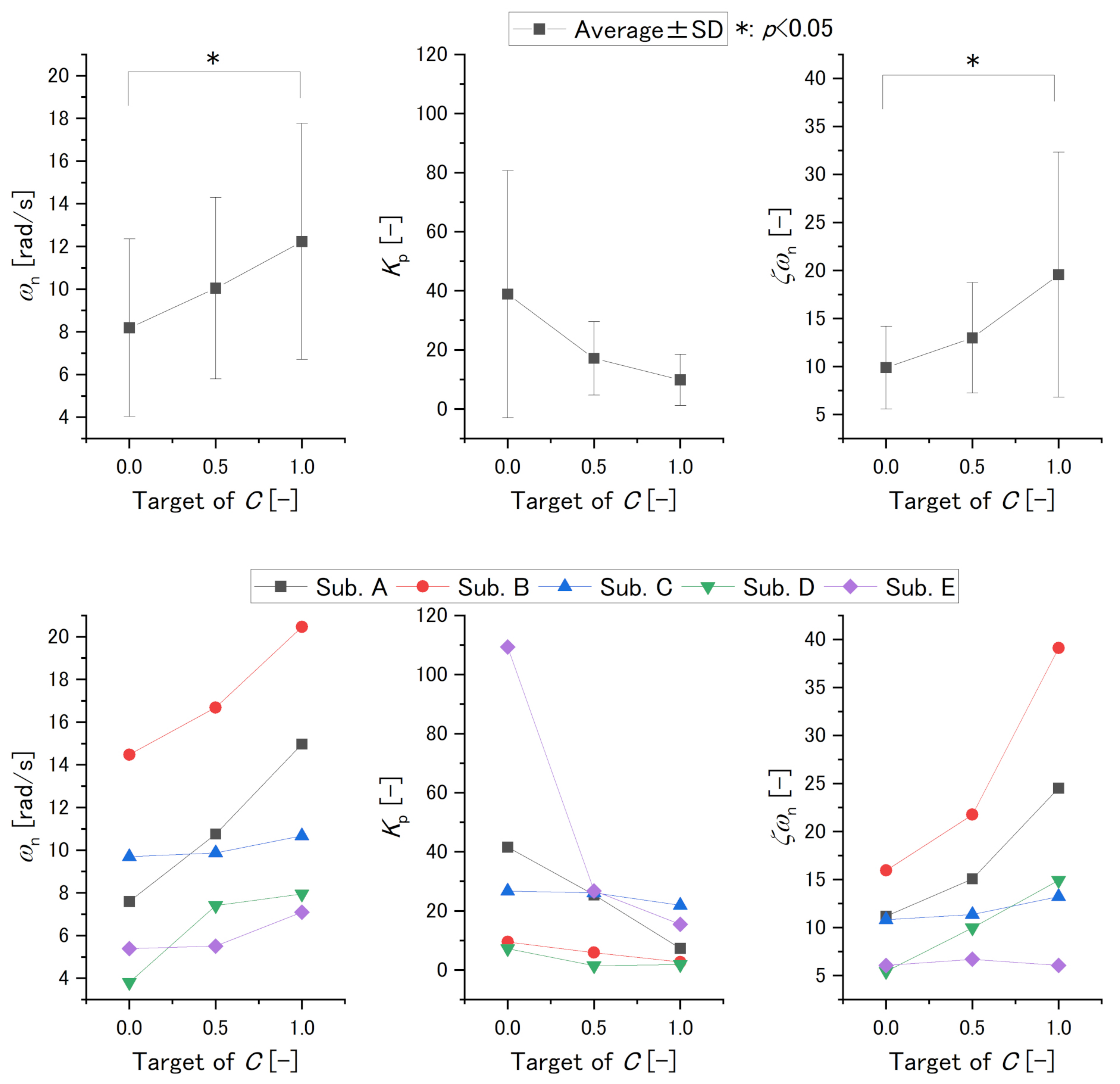
| [rad/s] | 8.2 | 10.0 | 12.2 | 4.2 | 4.2 | 5.5 | |
| [-] | 38.9 | 17.1 | 9.9 | 41.8 | 12.4 | 8.7 | |
| [-] | 9.9 | 13.0 | 20.0 | 4.3 | 5.8 | 12.7 | |
| values [-] | |||||||
| Target of [-] | 0.0–0.5 | 0.0–1.0 | 0.5–1.0 | ||||
| Variable | |||||||
| 0.08 | 0.003 | 0.05 | |||||
| 0.16 | 0.06 | 0.60 | |||||
| 0.34 | 0.01 | 0.06 | |||||
| Variable | Significant Difference | Individual Evaluation |
|---|---|---|
| (Relationship of Variable and C’s Target ) | ||
| C’s target of 0.0 and 1.0 | Positive | |
| No significant difference | Negative | |
| C’s target of 0.0 and 1.0 | Positive or cannot determine |
Publisher’s Note: MDPI stays neutral with regard to jurisdictional claims in published maps and institutional affiliations. |
© 2022 by the authors. Licensee MDPI, Basel, Switzerland. This article is an open access article distributed under the terms and conditions of the Creative Commons Attribution (CC BY) license (https://creativecommons.org/licenses/by/4.0/).
Share and Cite
Matsui, K.; Suzuki, Y.; Atsuumi, K.; Nagai, M.; Ohno, S.; Hirai, H.; Nishikawa, A.; Taniguchi, K. Earable Ω (OMEGA): A Novel Clenching Interface Using Ear Canal Sensing for Human Metacarpophalangeal Joint Control by Functional Electrical Stimulation. Sensors 2022, 22, 7412. https://doi.org/10.3390/s22197412
Matsui K, Suzuki Y, Atsuumi K, Nagai M, Ohno S, Hirai H, Nishikawa A, Taniguchi K. Earable Ω (OMEGA): A Novel Clenching Interface Using Ear Canal Sensing for Human Metacarpophalangeal Joint Control by Functional Electrical Stimulation. Sensors. 2022; 22(19):7412. https://doi.org/10.3390/s22197412
Chicago/Turabian StyleMatsui, Kazuhiro, Yuya Suzuki, Keita Atsuumi, Miwa Nagai, Shotaro Ohno, Hiroaki Hirai, Atsushi Nishikawa, and Kazuhiro Taniguchi. 2022. "Earable Ω (OMEGA): A Novel Clenching Interface Using Ear Canal Sensing for Human Metacarpophalangeal Joint Control by Functional Electrical Stimulation" Sensors 22, no. 19: 7412. https://doi.org/10.3390/s22197412
APA StyleMatsui, K., Suzuki, Y., Atsuumi, K., Nagai, M., Ohno, S., Hirai, H., Nishikawa, A., & Taniguchi, K. (2022). Earable Ω (OMEGA): A Novel Clenching Interface Using Ear Canal Sensing for Human Metacarpophalangeal Joint Control by Functional Electrical Stimulation. Sensors, 22(19), 7412. https://doi.org/10.3390/s22197412