
A Machine Learning Approach to Improve Ranging Accuracy with AoA and RSSI


Abstract
:1. Introduction
2. Related Work
2.1. RSSI-Based IPSs
2.2. AoA-Based IPSs
2.3. ANN-Based IPSs
3. Methodology
3.1. RSSI
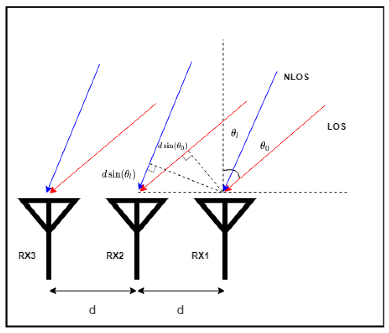
3.2. AoA Estimation
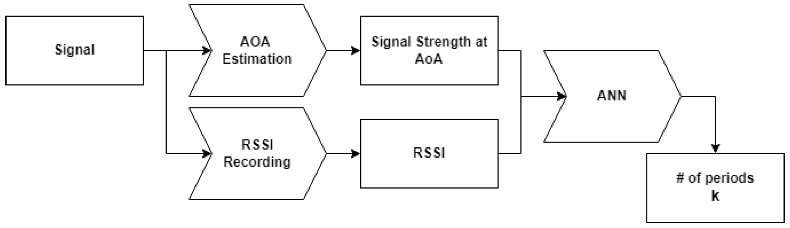
3.3. ANN
4. Experiment
4.1. Experimental Devices
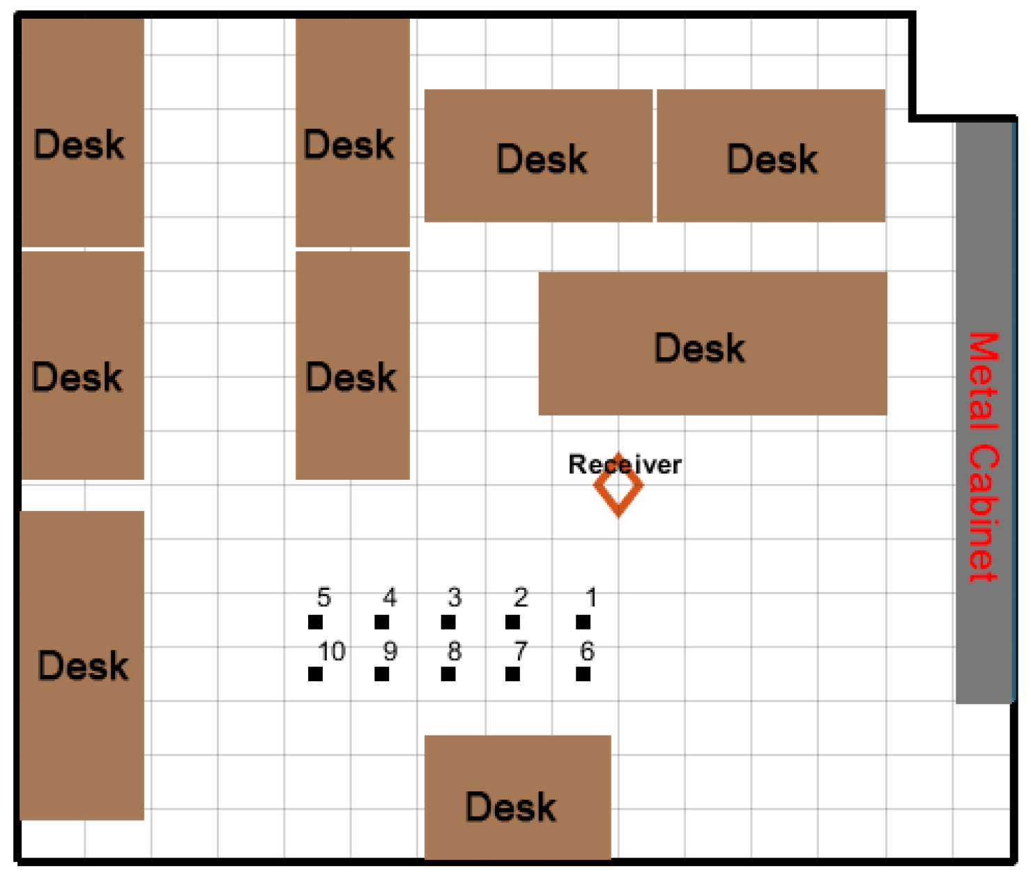
4.2. Experimental Setup
4.3. Experimental Process
- 1.
- Create an indoor environment and record the geometry of the selected transmitter location points, i.e., their coordinates, distance, and theoretical AoA.
- 2.
- Record the RSSI and the signal waveform.
- 3.
- Translate the signal waveform to the AoA spectrum and construct a dataset for the training stage.
- 4.
- Use the dataset to train the ANN and to obtain the weight factors of the model.
- 5.
- Estimate the number of periods T using the ANN and signal parameters.
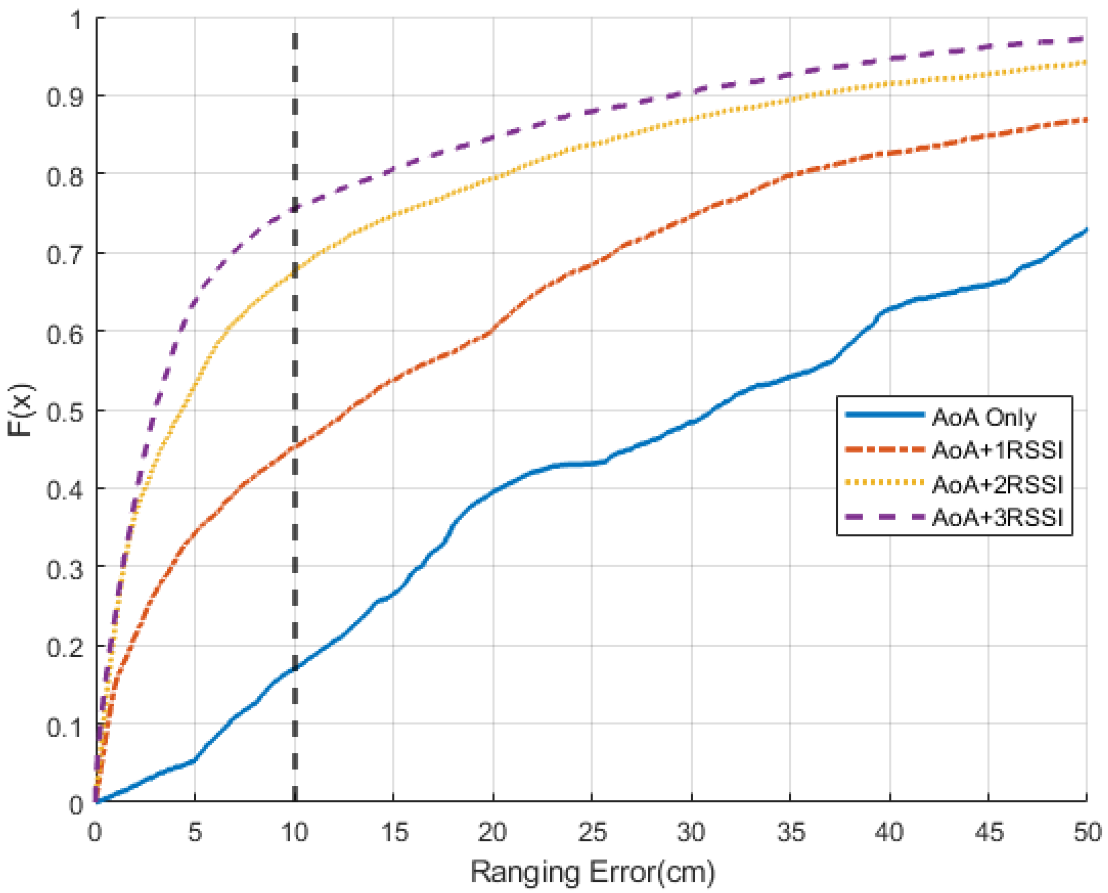
5. Result and Limitations
6. Conclusions
Author Contributions
Funding
Institutional Review Board Statement
Informed Consent Statement
Data Availability Statement
Conflicts of Interest
Appendix A

| Index | X | Y | AoA | Distance | Periods |
|---|---|---|---|---|---|
| 1 | 0.49 | 1.77 | 15.62 | 2.16 | 39 |
| 2 | 0.99 | 1.82 | 28.78 | 2.36 | 43 |
| 3 | 1.67 | 1.74 | 43.6 | 2.64 | 48 |
| 4 | 2.3 | 1.74 | 52.89 | 3.08 | 56 |
| 5 | 2.8 | 1.71 | 58.23 | 3.44 | 63 |
| 6 | 0.45 | 2.36 | 10.79 | 2.68 | 49 |
| 7 | 0.96 | 2.33 | 22.13 | 2.78 | 51 |
| 8 | 1.56 | 2.31 | 34.02 | 3.01 | 55 |
| 9 | 2.1 | 2.33 | 42.02 | 3.32 | 61 |
| 10 | 2.75 | 2.38 | 49.22 | 3.78 | 69 |
References
- Zafari, F.; Gkelias, A.; Leung, K.K. A survey of indoor localization systems and technologies. IEEE Commun. Surv. Tutor. 2019, 21, 2568–2599. [Google Scholar] [CrossRef]
- Kunhoth, J.; Karkar, A.; Al-Maadeed, S.; Al-Ali, A. Indoor positioning and wayfinding systems: A survey. Hum.-Centric Comput. Inf. Sci. 2020, 10, 18. [Google Scholar] [CrossRef]
- Sakpere, W.; Adeyeye-Oshin, M.; Mlitwa, N.B. A state-of-the-art survey of indoor positioning and navigation systems and technologies. S. Afr. Comput. J. 2017, 29, 145–197. [Google Scholar] [CrossRef]
- Zhao, S.; Liu, H. Transmitter-side multipath preprocessing for pulsed UWB systems considering pulse overlapping and narrow-band interference. IEEE Trans. Veh. Technol. 2007, 56, 3502–3510. [Google Scholar] [CrossRef]
- Zhao, S.; Orlik, P.; Molisch, A.F.; Liu, H.; Zhang, J. Hybrid ultrawideband modulations compatible for both coherent and transmit-reference receivers. IEEE Trans. Wirel. Commun. 2007, 6, 2551–2559. [Google Scholar] [CrossRef]
- Zhao, S.; Liu, H. Prerake diversity combining for pulsed UWB systems considering realistic channels with pulse overlapping and narrow-band interference. In Proceedings of the GLOBECOM’05, IEEE Global Telecommunications Conference, St. Louis, MO, USA, 28 Novembe–2 December 2005; pp. 5–3788. [Google Scholar]
- Saab, S.S.; Nakad, Z.S. A standalone RFID indoor positioning system using passive tags. IEEE Trans. Ind. Electron. 2010, 58, 1961–1970. [Google Scholar] [CrossRef]
- Agarwal, H.; Sanghvi, N.; Roy, V.; Kitani, K. DeepBLE: Generalizing RSSI-based Localization Across Different Devices. arXiv 2021, arXiv:2103.00252. [Google Scholar]
- Suraweera, N.; Li, S.; Johnson, M.; Collings, I.B.; Hanly, S.V.; Ni, W.; Hedley, M. Environment-assisted passive WiFi tracking with self-localizing asynchronous sniffers. IEEE Syst. J. 2020, 14, 4798–4809. [Google Scholar] [CrossRef]
- Li, S.; Hedley, M.; Bengston, K.; Humphrey, D.; Johnson, M.; Ni, W. Passive localization of standard WiFi devices. IEEE Syst. J. 2019, 13, 3929–3932. [Google Scholar] [CrossRef]
- Mandal, A.; Lopes, C.V.; Givargis, T.; Haghighat, A.; Jurdak, R.; Baldi, P. Beep: 3D indoor positioning using audible sound. In Proceedings of the Second IEEE Consumer Communications and Networking Conference, Las Vegas, NV, USA, 6 January 2005; pp. 348–353. [Google Scholar]
- Liu, K.; Liu, X.; Li, X. Guoguo: Enabling fine-grained indoor localization via smartphone. In Proceedings of the 11th Annual International Conference on Mobile Systems, Applications, and Services, Taipei, Taiwan, 25–28 June 2013; pp. 235–248. [Google Scholar]
- Ma, Y.; Wang, B.; Pei, S.; Zhang, Y.; Zhang, S.; Yu, J. An indoor localization method based on AOA and PDOA using virtual stations in multipath and NLOS environments for passive UHF RFID. IEEE Access 2018, 6, 31772–31782. [Google Scholar] [CrossRef]
- Chen, L.; Ahriz, I.; Le Ruyet, D. AoA-aware probabilistic indoor location fingerprinting using channel state information. IEEE Int. Things J. 2020, 7, 10868–10883. [Google Scholar] [CrossRef] [Green Version]
- Gjengset, J.; Xiong, J.; McPhillips, G.; Jamieson, K. Phaser: Enabling phased array signal processing on commodity WiFi access points. In Proceedings of the 20th annual international conference on Mobile computing and networking, Maui, HI, USA, 7–11 September 2014; pp. 153–164. [Google Scholar]
- Martin, E.; Vinyals, O.; Friedland, G.; Bajcsy, R. Precise indoor localization using smart phones. In Proceedings of the 18th ACM International Conference on Multimedia, Firenze, Italy, 25–29 October 2010; pp. 787–790. [Google Scholar]
- Achroufene, A.; Amirat, Y.; Chibani, A. RSS-Based Indoor Localization Using Belief Function Theory. IEEE Trans. Autom. Sci. Eng. 2018, 16, 1163–1180. [Google Scholar] [CrossRef]
- Biehl, J.T.; Cooper, M.; Filby, G.; Kratz, S. Loco: A ready-to-deploy framework for efficient room localization using wi-fi. In Proceedings of the 2014 ACM International Joint Conference on Pervasive and Ubiquitous Computing, Seattle, WA, USA, 13–17 September 2014; pp. 183–187. [Google Scholar]
- Vasisht, D.; Kumar, S.; Katabi, D. Decimeter-Level Localization with a Single WiFi Access Point. In Proceedings of the 13th USENIX Symposium on Networked Systems Design and Implementation (NSDI 16), Santa Clara, CA, USA, 16–18 March 2018; pp. 165–178. [Google Scholar]
- Afousi, M.B.; Zoghi, M.R. Wi-Fi RSS indoor positioning system using online layer clustering and weighted DCP-KNN. In Proceedings of the 2018 26th Iranian Conference on Electrical Engineering (ICEE), Mashhad, Iran, 8–10 May 2018; pp. 710–715. [Google Scholar]
- Du, C.; Peng, B.; Zhang, Z.; Xue, W.; Guan, M. KF-KNN: Low-cost and high-accurate FM-based indoor localization model via fingerprint technology. IEEE Access 2020, 8, 197523–197531. [Google Scholar] [CrossRef]
- Goldoni, E.; Savioli, A.; Risi, M.; Gamba, P. Experimental analysis of RSSI-based indoor localization with IEEE 802.15.4. In Proceedings of the 2010 European Wireless Conference (EW), Lucca, Italy, 12–15 April 2010; pp. 71–77. [Google Scholar]
- Youssef, M.; Agrawala, A. The Horus WLAN location determination system. In Proceedings of the 3rd International Conference on Mobile Systems, Applications, and Services, Washington, DC, USA, 6–8 June 2005; pp. 205–218. [Google Scholar]
- Yang, J.; Chen, Y. Indoor localization using improved rss-based lateration methods. In Proceedings of the GLOBECOM 2009—2009 IEEE Global Telecommunications Conference, Honolulu, HI, USA, 30 November–4 December 2009; pp. 1–6. [Google Scholar]
- Li, Z.; Tian, Z.; Wang, Z.; Zhang, Z. Multipath-assisted indoor localization using a single receiver. IEEE Sens. J. 2020, 21, 692–705. [Google Scholar] [CrossRef]
- Kumar, S.; Gil, S.; Katabi, D.; Rus, D. Accurate indoor localization with zero start-up cost. In Proceedings of the 20th Annual International Conference on Mobile Computing and Networking, Maui, HI, USA, 7–11 September 2014; pp. 483–494. [Google Scholar]
- Xiong, J.; Jamieson, K. ArrayTrack: A Fine-Grained Indoor Location System. In Proceedings of the 10th USENIX Symposium on Networked Systems Design and Implementation (NSDI 13), Lombard, IL, USA, 2–5 April 2013; pp. 71–84. [Google Scholar]
- Adege, A.B.; Yayeh, Y.; Berie, G.; Lin, H.-P.; Yen, L.; Li, Y.R. Indoor localization using K-nearest neighbor and artificial neural network back propagation algorithms. In Proceedings of the 2018 27th Wireless and Optical Communication Conference (WOCC), Hualien, Taiwan, 30 April–1 May 2018; pp. 1–2. [Google Scholar]
- Ibrahim, A.; Rahim, S.K.A.; Mohamad, H. Performance evaluation of RSS-based WSN indoor localization scheme using artificial neural network schemes. In Proceedings of the 2015 IEEE 12th Malaysia International Conference on Communications (MICC), Kuching, Malaysia, 23–25 November 2015; pp. 300–305. [Google Scholar]
- Adhikari, B.; Fernando, X.N. A Neural Network Based Recursive Least Square Multilateration Technique for Indoor Positioning. In Proceedings of the 2021 IEEE 26th International Workshop on Computer Aided Modeling and Design of Communication Links and Networks (CAMAD), Porto, Portugal, 25–27 October 2021; pp. 1–6. [Google Scholar]
- Viswanathan, M. Wireless Communication Systems in Matlab; Independently Published; 2020. Available online: https://www.gaussianwaves.com/wireless-communication-systems-in-matlab (accessed on 1 June 2020).
- Capon, J.; Greenfield, R.J.; Kolker, R. Multidimensional maximum-likelihood processing of a large aperture seismic array. Proc. IEEE 1967, 55, 192–211. [Google Scholar] [CrossRef]
- Van Trees, H.L. Optimum Array Processing: Part IV of Detection, Estimation, and Modulation Theory; John Wiley & Sons: Hoboken, NJ, USA, 2004. [Google Scholar]
- Gentilho, E.; Scalassara, P.R.; Abrão, T. Direction-of-arrival estimation methods: A performance-complexity tradeoff perspective. J. Signal Process. Syst. 2020, 92, 239–256. [Google Scholar] [CrossRef]
- Abiodun, O.I.; Jantan, A.; Omolara, A.E.; Dada, K.V.; Mohamed, N.A.; Arshad, H. State-of-the-art in artificial neural network applications: A survey. Heliyon 2018, 4, e00938. [Google Scholar] [CrossRef] [PubMed]
- MacKay, D. Bayesian interpolation. Neural Comput. 1992, 4, 415–447. [Google Scholar] [CrossRef]


| Study | Method | Median Error | # of APs |
|---|---|---|---|
| Martin et al. [16] | RSSI-fingerprint | 1.5 m | 3 |
| Achroufene et al. [17] | RSSI-ranging | 1.13 m | 5 |
| Biehl et al. [18] | RSSI-fingerprint | 0.94 m | 7 |
| Chen et al. [25] | AoA | 1.5 m | 1 |
| Kumar et al. [26] | AoA | 0.3 m | 5 |
| Xiong et al. [27] | AoA | 0.23 m | 6 |
| Adege et al. [28] | ANN | 0.5 m | 7 |
| Ibrahim et al. [29] | ANN | 0.49 m | 1 |
| Adhikari et al. [30] | ANN | 0.035 m | 10 |
| Properties | Value |
|---|---|
| Input | , RSSI1, RSSI2, RSSI3 |
| Output | # of Periods |
| Algorithm | Bayesian Regularization |
| Layers | 30 |
| Loss Function | mse |
Publisher’s Note: MDPI stays neutral with regard to jurisdictional claims in published maps and institutional affiliations. |
© 2022 by the authors. Licensee MDPI, Basel, Switzerland. This article is an open access article distributed under the terms and conditions of the Creative Commons Attribution (CC BY) license (https://creativecommons.org/licenses/by/4.0/).
Share and Cite
Zhang, T.; Zhang, P.; Kalathas, P.; Wang, G.; Liu, H. A Machine Learning Approach to Improve Ranging Accuracy with AoA and RSSI. Sensors 2022, 22, 6404. https://doi.org/10.3390/s22176404
Zhang T, Zhang P, Kalathas P, Wang G, Liu H. A Machine Learning Approach to Improve Ranging Accuracy with AoA and RSSI. Sensors. 2022; 22(17):6404. https://doi.org/10.3390/s22176404
Chicago/Turabian StyleZhang, Tingwei, Peng Zhang, Paris Kalathas, Guangxin Wang, and Huaping Liu. 2022. "A Machine Learning Approach to Improve Ranging Accuracy with AoA and RSSI" Sensors 22, no. 17: 6404. https://doi.org/10.3390/s22176404
APA StyleZhang, T., Zhang, P., Kalathas, P., Wang, G., & Liu, H. (2022). A Machine Learning Approach to Improve Ranging Accuracy with AoA and RSSI. Sensors, 22(17), 6404. https://doi.org/10.3390/s22176404