
Split Ring Resonator Network and Diffused Sensing Element Embedded in a Concrete Beam for Structural Health Monitoring

 ,
,  ,
,  , ,
, ,  and
and 
Abstract
:1. Introduction
2. Split Ring Resonator Network Design
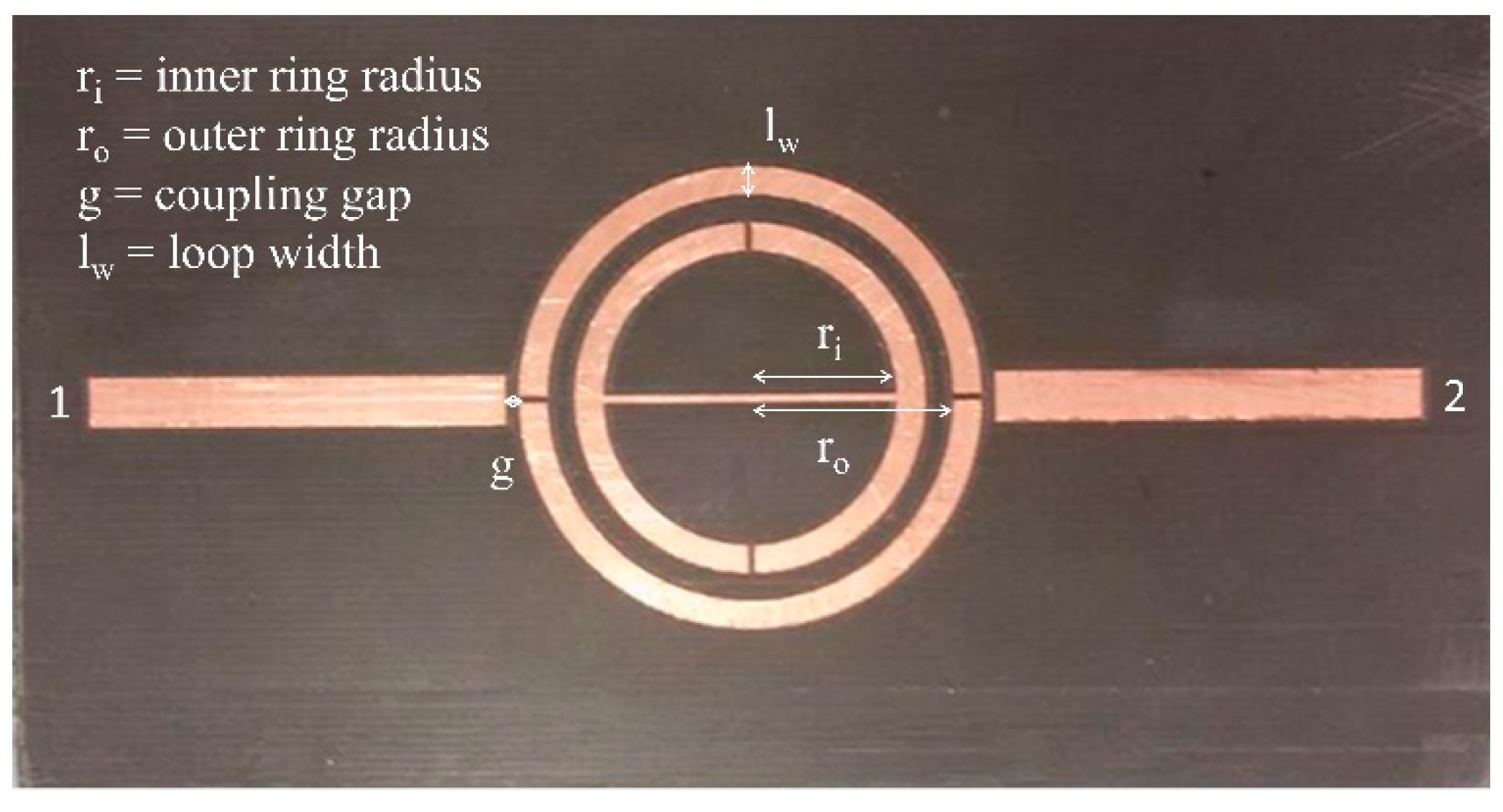
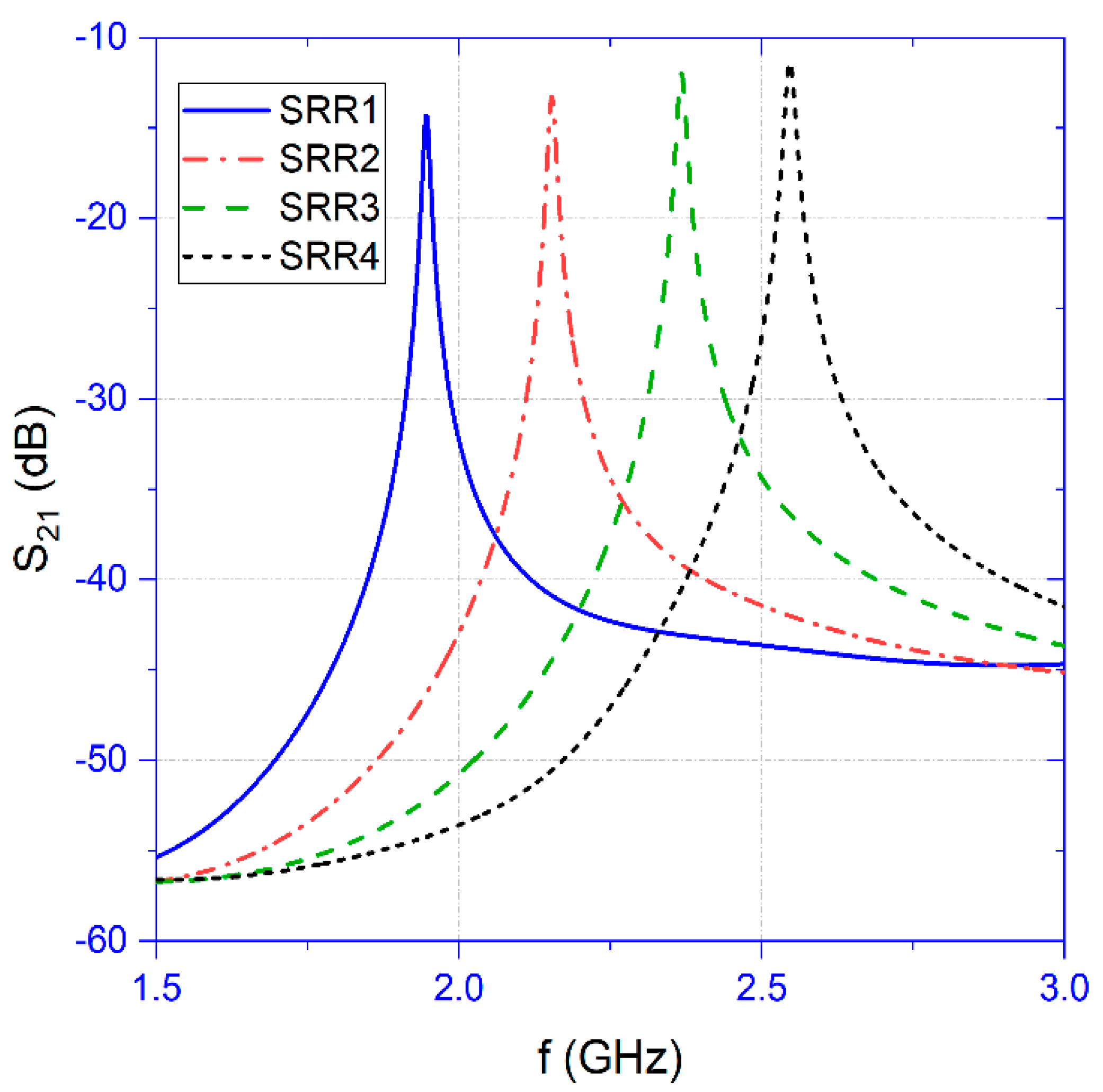
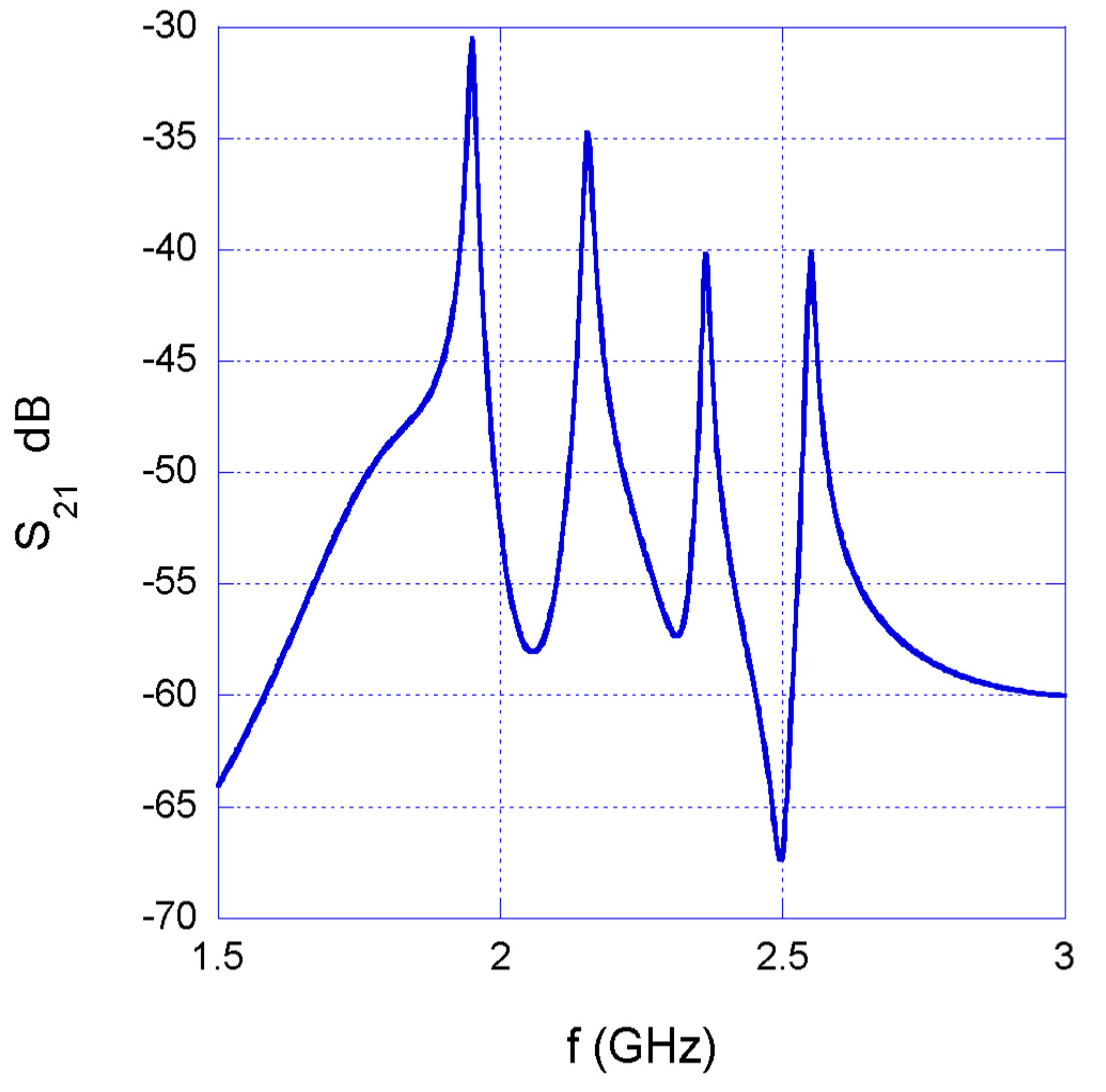
2.1. SRR Network
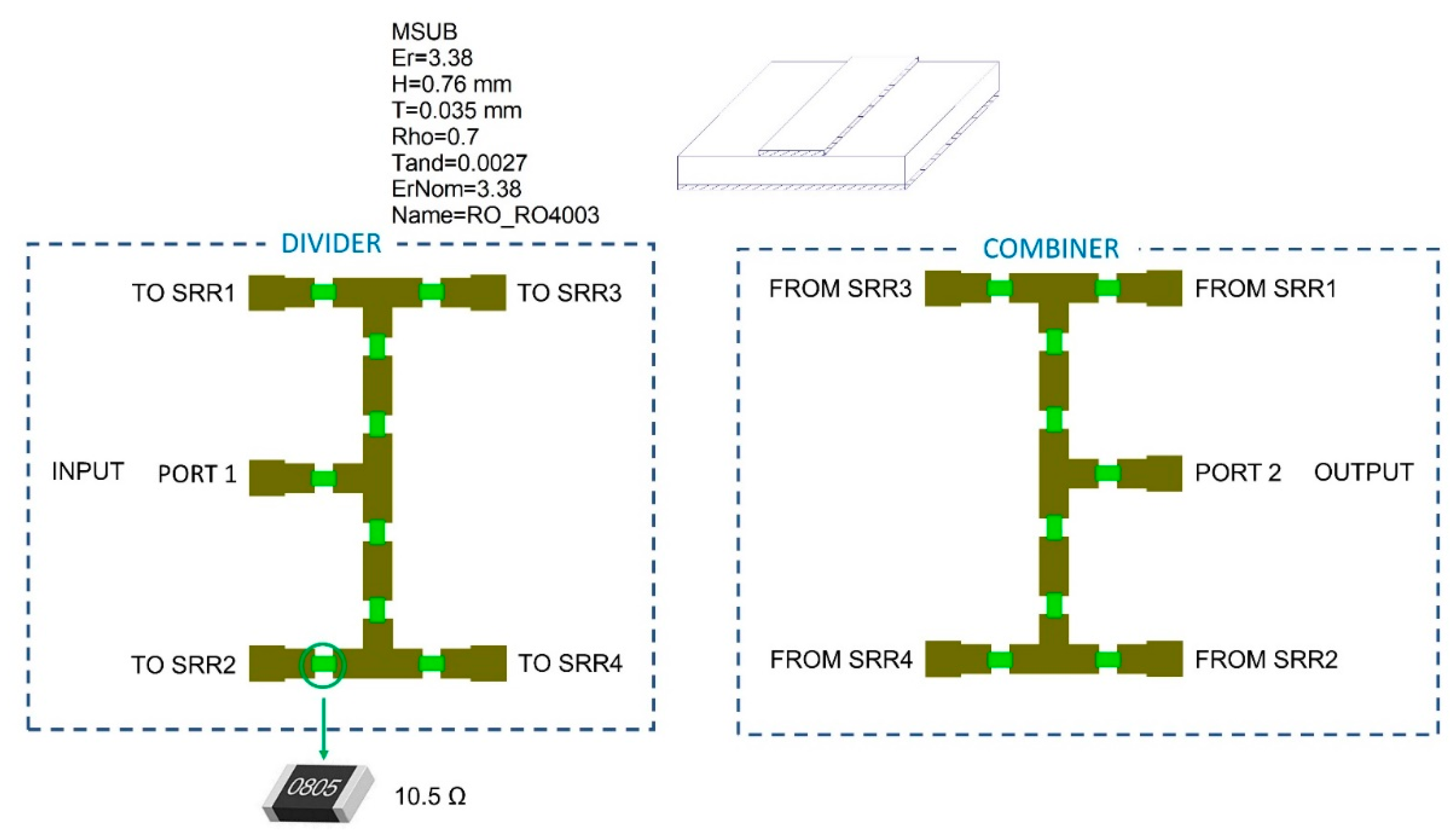
2.2. Power Divider
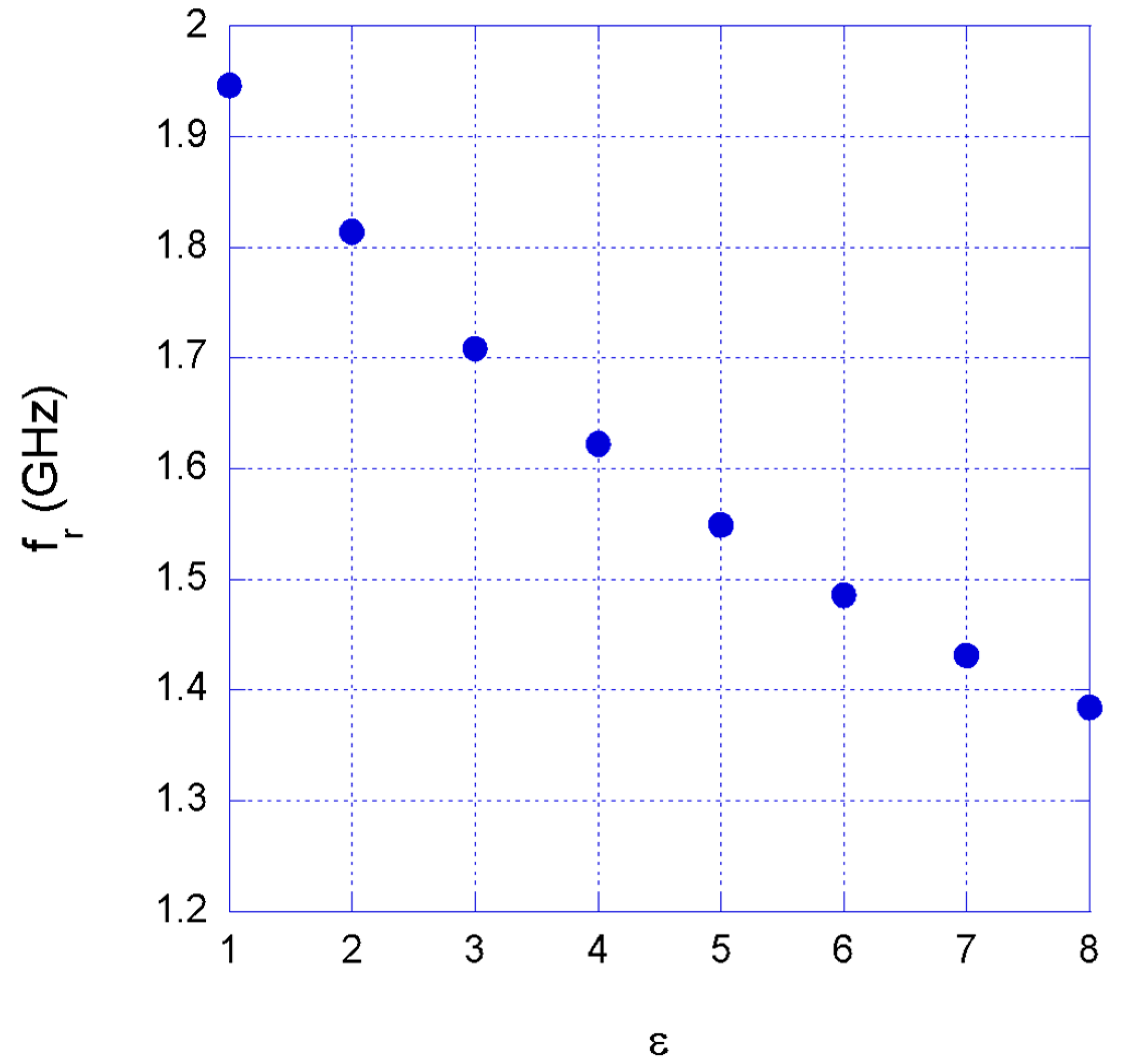
2.3. Permittivity Detection through SRR Network
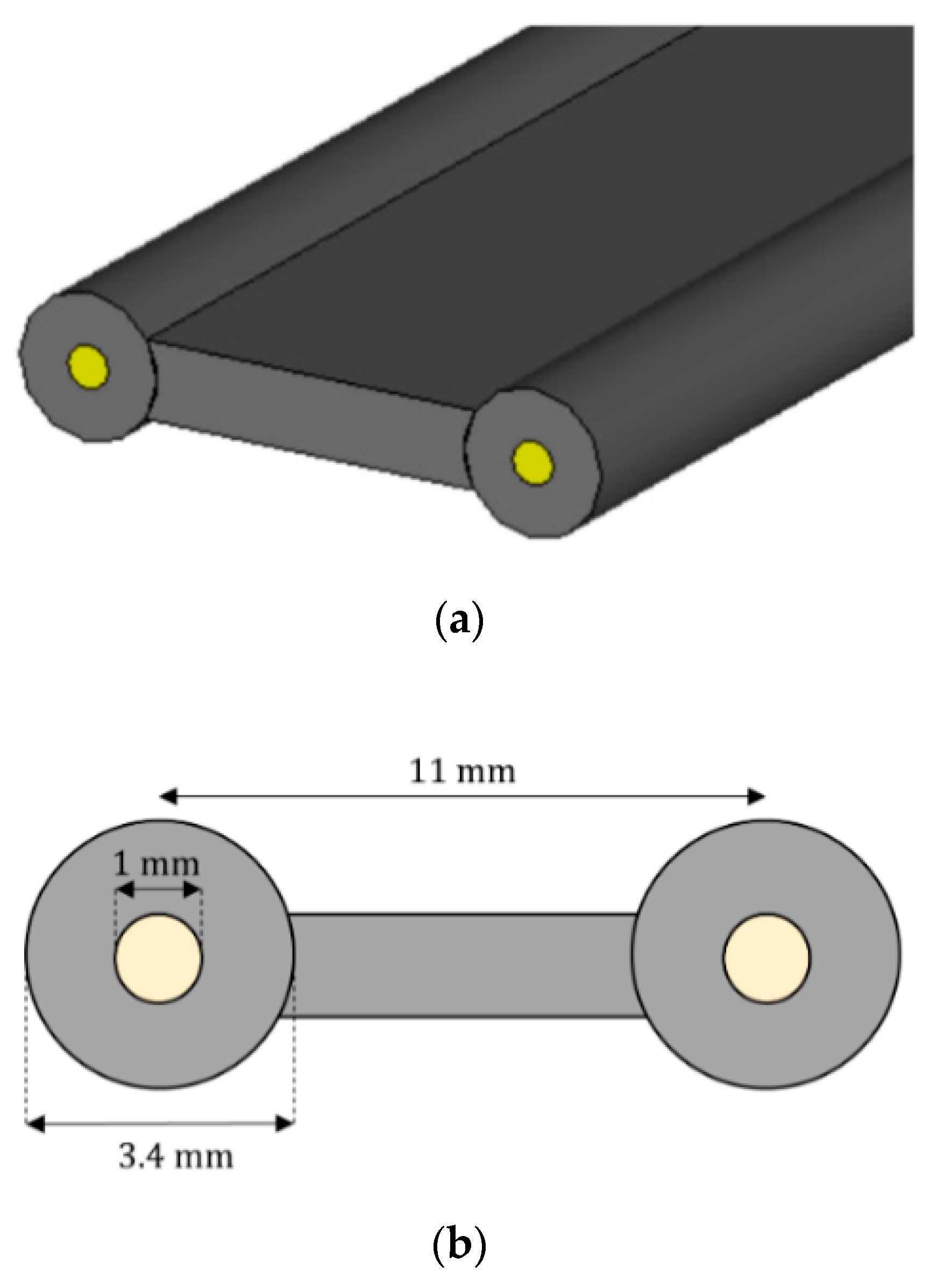
2.4. Wire-Like Diffused Sensing Element
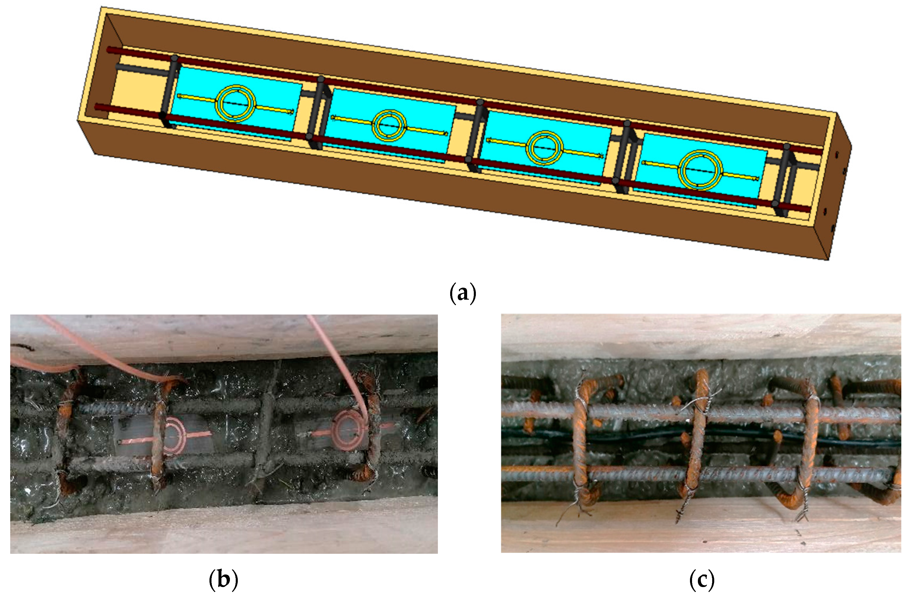
3. Experimental Set-Up
4. Results
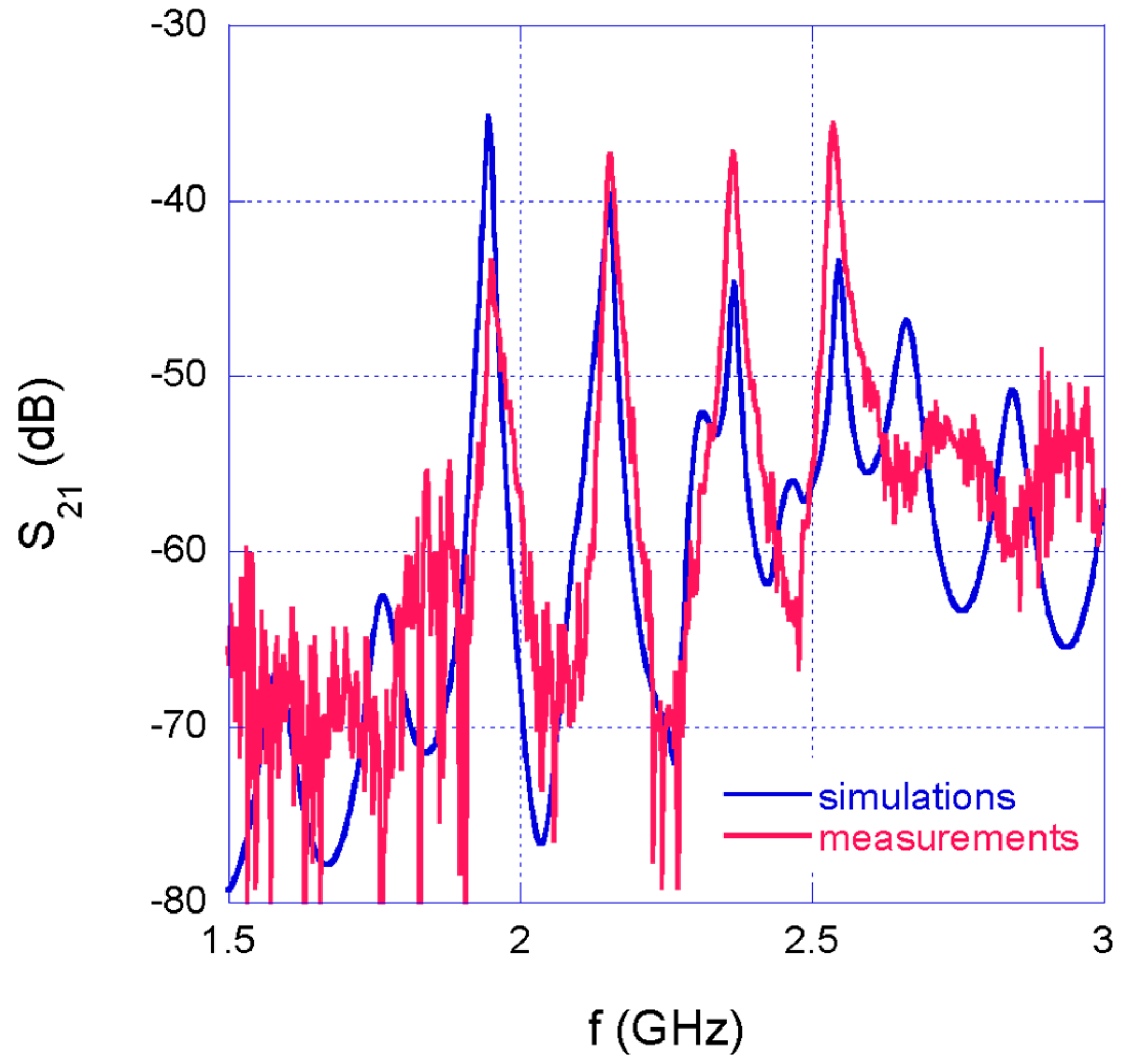
4.1. Measurements in Air
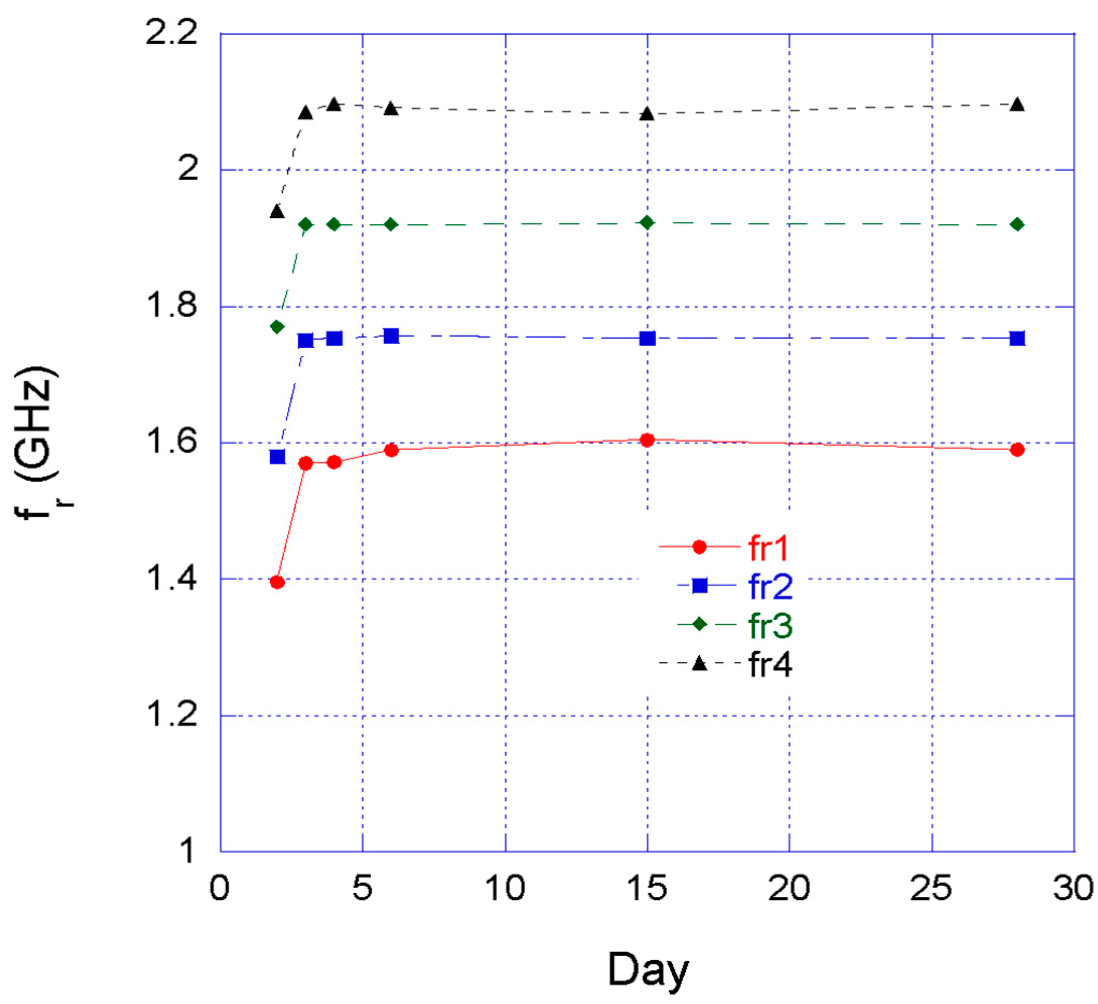
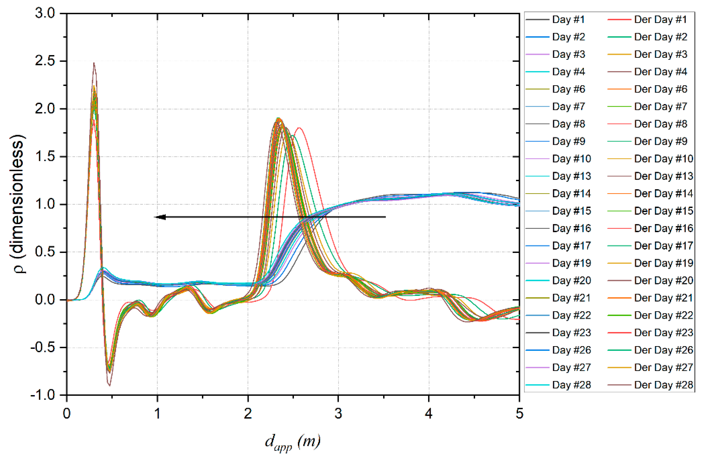
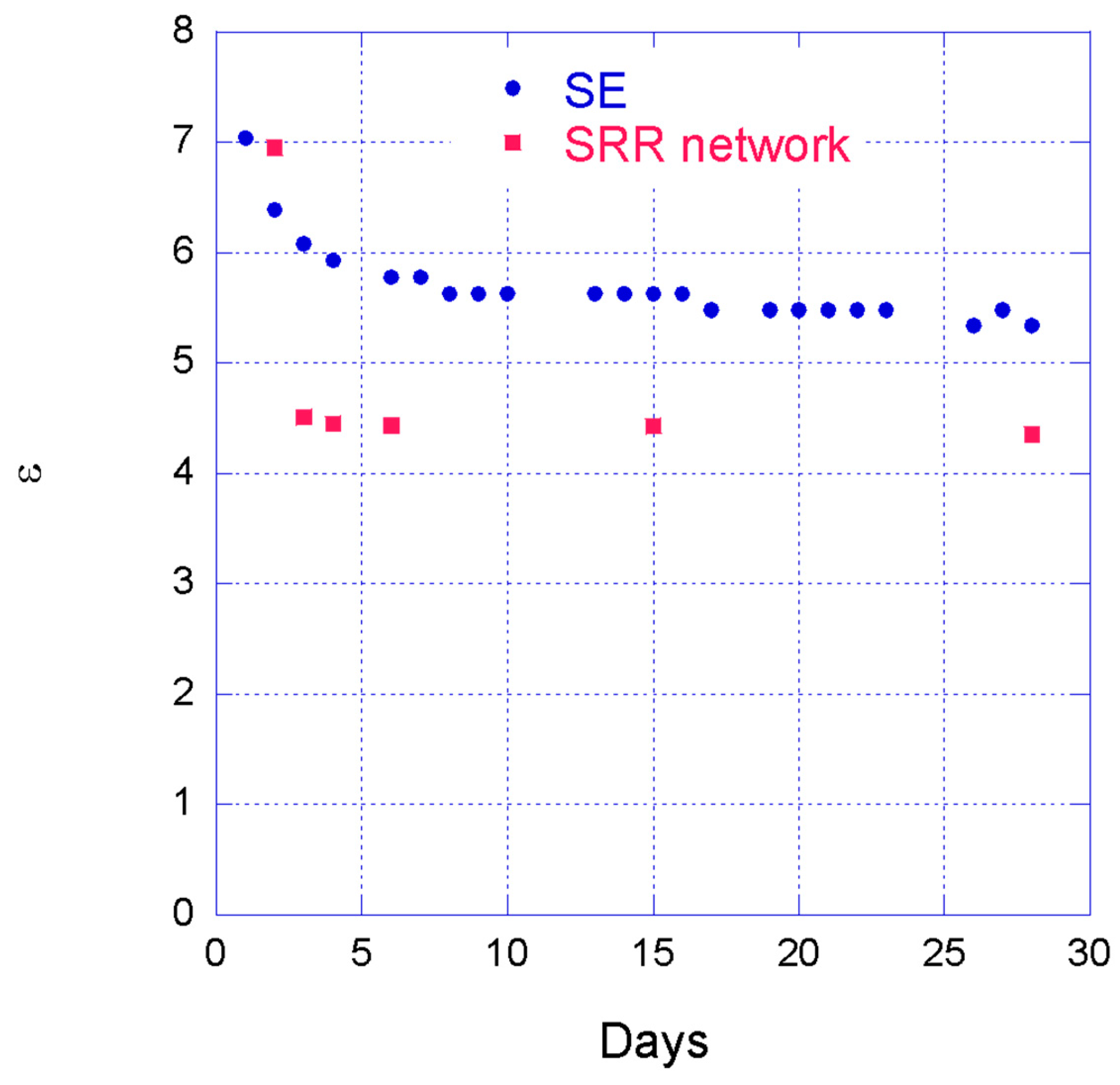
4.2. Measurements in the Concrete Beam
5. Conclusions
Author Contributions
Funding
Institutional Review Board Statement
Informed Consent Statement
Data Availability Statement
Acknowledgments
Conflicts of Interest
References
- Lynch, J.P.; Loh, K.J. A summary review of wireless sensors and sensor networks for structural health monitoring. Shock. Vib. Dig. 2006, 38, 91–128. [Google Scholar] [CrossRef]
- Sony, S.; Laventure, S.; Sadhu, A. A literature review of next-generation smart sensing technology in structural health monitoring. Struct. Control Health Monit. 2019, 26, e2321. [Google Scholar] [CrossRef]
- Alzughaibi, A.A.; Ibrahim, A.M.; Na, Y.; El-Tawil, S.; Eltawil, A.M. Community-Based Multi-Sensory Structural Health Monitoring System: A Smartphone Accelerometer and Camera Fusion Approach. IEEE Sens. J. 2021, 21, 20539–20551. [Google Scholar] [CrossRef]
- di Nuzzo, F.; Brunelli, D.; Polonelli, T.; Benini, L. Structural Health Monitoring System with Narrowband IoT and MEMS Sensors. IEEE Sens. J. 2021, 21, 16371–16380. [Google Scholar] [CrossRef]
- Carino, N.J.; Meeks, K.W. Curing of High-Performance Concrete: Phase I Study; National Institute of Standards and Technology Report; US Department of Commerce, Technology Administration, National Institute of Standards and Technology: Gaithersburg, MD, USA, 2001; Volume 6505.
- How To Pour Concrete, from Prep Work to Curing. Available online: https://www.concretenetwork.com/install-concrete.html (accessed on 28 June 2022).
- Teng, K.H.; Kot, P.; Muradov, M.; Shaw, A.; Hashim, K.; Gkantou, M.; Al-Shamma’a, A. Embedded smart antenna for nondestructive testing and evaluation (NDT&E) of moisture content and deterioration in concrete. Sensors 2019, 19, 547. [Google Scholar]
- Kot, P.; Shaw, A.; Riley, M.; Cotgrave, A. The feasibility of using electromagnetic waves in determining membrane failure through concrete. Int. J. Civ. Eng. 2017, 15, 355–362. [Google Scholar] [CrossRef]
- Gkantou, M.; Muradov, M.; Kamaris, G.S.; Hashim, K.; Atherton, W.; Kot, P. Novel electromagnetic sensors embedded in reinforced concrete beams for crack detection. Sensors 2019, 19, 5175. [Google Scholar] [CrossRef]
- Pittella, E.; Angrisani, L.; Cataldo, A.; Piuzzi, E.; Fabbrocino, F. Embedded Split Ring Resonator Network for Health Monitoring in Concrete Structures. IEEE Instrum. Meas. Mag. 2020, 23, 14–20. [Google Scholar] [CrossRef]
- Cataldo, A.; Schiavoni, R.; Masciullo, A.; Cannazza, G.; Micelli, F.; de Benedetto, E. Combined Punctual and Diffused Monitoring of Concrete Structures Based on Dielectric Measurements. Sensors 2021, 21, 4872. [Google Scholar] [CrossRef]
- Aydin, K.; Bulu, I.; Guven, K.; Kafesaki, M.; Soukoulis, C.M.; Ozbay, E. Investigation of magnetic resonances for different split-ring-resonator parameters and designs. New J. Phys. 2005, 7, 168. [Google Scholar] [CrossRef]
- Alahnomi, R.A.; Zakaria, Z.; Ruslan, E.; Rosmaniza, S.; Rashid, A.; Bahar, A.A.M. High-Q sensor based on symmetrical split ring resonator with spurlines for solids material detection. IEEE Sens. J. 2017, 17, 2766–2775. [Google Scholar] [CrossRef]
- Alahnomi, R.A.; Zakaria, Z.; Ruslan, E.; Bahar, A.A.M.; Rashid, S.R.A. High sensitive microwave sensor based on symmetrical split ring resonator for material characterization. Microw. Opt. Technol. Lett. 2016, 58, 2106–2110. [Google Scholar] [CrossRef]
- Boybay, M.S.; Ramahi, O.M. Material characterization using complementary split ring resonators. IEEE Trans. Instrum. Meas. 2012, 61, 3039–3046. [Google Scholar] [CrossRef]
- Abegaonkar, M.P.; Karekar, R.N.; Aiyer, R.C. A microwave microstrip ring resonator as a moisture sensor for biomaterials: Applications to wheat grains. Meas. Sci. Technol. 1999, 10, 195. [Google Scholar] [CrossRef]
- Piuzzi, E.; Cannazza, G.; Cataldo, A.; de Benedetto, E.; de Giorgi, L.; Frezza, F.; Leucci, G.; Pisa, S.; Pittella, E.; Prontera, S.; et al. A comparative assessment of microwave-based methods for moisture content characterization in stone materials. Measurement 2018, 114, 493–500. [Google Scholar] [CrossRef]
- Alahnomi, R.A.; Zakaria, Z.; Ruslan, E.; Bahar, A.A.M.; Rashid, S.R.A. A novel microwave sensor with high-Q symmetrical split ring resonator for material properties measurement. J. Teknol. 2016, 78, 37–42. [Google Scholar] [CrossRef]
- CST Studio Suite. 3DS.com. Dassault Systèmes Deutschland GmbH, 2019. Available online: https://www.3ds.com/products-services/simulia/products/cst-studio-suite/ (accessed on 28 June 2022).
- AD Series Data Sheet—AD250C, AD255C, AD300D and AD350A. 2022. Available online: https://rogerscorp.com/-/media/project/rogerscorp/documents/advanced-electronics-solutions/english/data-sheets/ad-series-data-sheet---ad250c-ad255c-ad300d-ad350a.pdf (accessed on 28 June 2022).
- “RF/Microwave Design”, Cadence Microwave Office, RF and Microwave Circuit Design Software, v14.03r. 2022. Available online: https://www.cadence.com/en_US/home/tools/systemanalysis/rf-microwave-design.html (accessed on 28 June 2022).
- Limer, T. >Electronic Engineering Times. Choosing and Using Resistive Power Splitters and Dividers. 2008. Available online: https://www.edn.com/choosing-and-using-resistive-power-splitters-and-dividers (accessed on 27 May 2022).
- Piuzzi, E.; Pittella, E.; Pisa, S.; Cataldo, A.; de Benedetto, E.; Cannazza, G. Microwave reflectometric methodologies for water content estimation in stone-made Cultural Heritage materials. Measurement 2018, 118, 275–281. [Google Scholar] [CrossRef]
- Cataldo, A.; de Benedetto, E.; Cannazza, G.; Masciullo, A.; Giaquinto, N.; D’Aucelli, G.; Costantino, N.; de Leo, A.; Miraglia, M. Recent advances in the TDR-based leak detection system for pipeline inspection. Measurement 2017, 98, 347–354. [Google Scholar] [CrossRef]
- Cataldo, A.; de Benedetto, E.; Cannazza, G.; Piuzzi, E.; Pittella, E. TDR-Based Measurements of Water Content in Construction Materials for In-the-Field Use and Calibration. IEEE Trans. Instrum. Meas. 2018, 67, 1230–1237. [Google Scholar] [CrossRef]
- Cataldo, A.; Cannazza, G.; de Benedetto, E.; Giaquinto, N. A TDR-based system for the localization of leaks in newly installed, underground pipes made of any material. Meas. Sci. Technol. 2012, 23, 105010. [Google Scholar] [CrossRef]
- Piuzzi, E.; Cataldo, A.; Cannazza, G.; de Benedetto, E. An Improved Reflectometric Method for Soil Moisture Measurement Exploiting an Innovative Triple-Short Calibration. IEEE Trans. Instrum. Meas. 2010, 59, 2747–2754. [Google Scholar] [CrossRef]
- Cataldo, A.; Monti, G.; de Benedetto, E.; Cannazza, G.; Tarricone, L.; Catarinucci, L. Assessment of a TD-Based Method for Characterization of Antennas. IEEE Trans. Instrum. Meas. 2009, 58, 1412–1419. [Google Scholar] [CrossRef]
- Giaquinto, N.; D’Aucelli, G.A.; de Benedetto, E.; Cannazza, G.; Cataldo, A.; Piuzzi, E.; Masciullo, A. Criteria for Automated Estimation of Time of Flight in TDR Analysis. IEEE Trans. Instrum. Meas. 2016, 65, 1215–1224. [Google Scholar] [CrossRef]
- Cataldo, A.; de Benedetto, E.; Cannazza, G.; Piuzzi, E.; Giaquinto, N. Embedded TDR wire-like sensing elements for monitoring applications. Measurement 2015, 68, 236–245. [Google Scholar] [CrossRef]
- Scarpetta, M.; Spadavecchia, M.; Andria, G.; Ragolia, M.A.; Giaquinto, N. Analysis of TDR Signals with Convolutional Neural Networks. In Proceedings of the I2MTC 2021—International Instrumentation and Measurement Technology Conference, Glasgow, Scotland, 17–20 May 2021. [Google Scholar]
- Scarpetta, M.; Spadavecchia, M.; Adamo, F.; Ragolia, M.A.; Giaquinto, N. Detection and characterization of multiple discontinuities in cables with time-domain reflectometry and convolutional neural networks. Sensors 2021, 21, 8032. [Google Scholar] [CrossRef] [PubMed]
- Pittella, E.; Piuzzi, E. Split Ring Resonator for Complex Permittivity Measurement. In Proceedings of the 24th IMEKO TC4 International Symposium and 22nd International Workshop on ADC and DAC Modelling and Testing, Palermo, Italy, 14–16 September 2020; p. 85. [Google Scholar]
- Feng, R.; Ratni, B.; Yi, J.; Zhang, H.; de Lustrac, A.; Burokur, S.N. Versatile metasurface platform for electromagnetic wave tailoring. Photonics Res. 2021, 9, 1650–1659. [Google Scholar] [CrossRef]
- Yu, Q.; Zheng, Y.N.; Gu, Z.; Liu, J.; Liang, Y.C.; Li, L.Z.; Zhang, X.G.; Jiang, W.X. Self-adaptive metasurface platform based on computer vision. Opt. Lett. 2021, 46, 3520–3523. [Google Scholar] [CrossRef]
- Silalahi, H.M.; Chen, Y.-P.; Shih, Y.-H.; Chen, Y.-S.; Lin, X.-Y.; Liu, J.-H.; Huang, C.-Y. Floating terahertz metamaterials with extremely large refractive index sensitivities. Photonics Res. 2021, 9, 1970–1978. [Google Scholar] [CrossRef]
- Song, X.; Yang, W.; Qu, K.; Bai, X.; Chen, K.; Feng, Y.; Zhu, W. Switchable metasurface for nearly perfect reflection, transmission, and absorption using PIN diodes. Opt. Express 2021, 29, 29320–29328. [Google Scholar] [CrossRef]
- Xu, R.; Xu, X.; Yang, B.-R.; Gui, X.; Qin, Z.; Lin, Y.-S. Actively logical modulation of MEMS-based terahertz metamaterial. Photonics Res. 2021, 9, 1409–1415. [Google Scholar] [CrossRef]


| SRR | ri (mm) | ro (mm) | g (mm) | lw (mm) |
|---|---|---|---|---|
| 1 | 14.0 | 18.0 | 0.44 | 2.0 |
| 2 | 12.4 | 16.4 | 0.44 | 2.0 |
| 3 | 11.0 | 15.0 | 0.44 | 2.0 |
| 4 | 10.0 | 14.0 | 0.44 | 2.0 |
| ε | 1 | 2 | 3 | 4 | 5 | 6 | 7 | 8 |
|---|---|---|---|---|---|---|---|---|
| fr,SRR1 | 1.9461 | 1.8141 | 1.7082 | 1.6224 | 1.5489 | 1.4856 | 1.4313 | 1.3842 |
| fr,SRR1 | 2.1531 | 2.0091 | 1.8894 | 1.7910 | 1.7109 | 1.6407 | 1.5771 | 1.5222 |
| fr,SRR3 | 2.3670 | 2.2101 | 2.0772 | 1.9710 | 1.8819 | 1.8039 | 1.7364 | 1.6737 |
| fr,SRR4 | 2.5464 | 2.3733 | 2.2347 | 2.1231 | 2.0268 | 1.9431 | 1.8690 | 1.8015 |
Publisher’s Note: MDPI stays neutral with regard to jurisdictional claims in published maps and institutional affiliations. |
© 2022 by the authors. Licensee MDPI, Basel, Switzerland. This article is an open access article distributed under the terms and conditions of the Creative Commons Attribution (CC BY) license (https://creativecommons.org/licenses/by/4.0/).
Share and Cite
Pittella, E.; Schiavoni, R.; Monti, G.; Masciullo, A.; Scarpetta, M.; Cataldo, A.; Piuzzi, E. Split Ring Resonator Network and Diffused Sensing Element Embedded in a Concrete Beam for Structural Health Monitoring. Sensors 2022, 22, 6398. https://doi.org/10.3390/s22176398
Pittella E, Schiavoni R, Monti G, Masciullo A, Scarpetta M, Cataldo A, Piuzzi E. Split Ring Resonator Network and Diffused Sensing Element Embedded in a Concrete Beam for Structural Health Monitoring. Sensors. 2022; 22(17):6398. https://doi.org/10.3390/s22176398
Chicago/Turabian StylePittella, Erika, Raissa Schiavoni, Giuseppina Monti, Antonio Masciullo, Marco Scarpetta, Andrea Cataldo, and Emanuele Piuzzi. 2022. "Split Ring Resonator Network and Diffused Sensing Element Embedded in a Concrete Beam for Structural Health Monitoring" Sensors 22, no. 17: 6398. https://doi.org/10.3390/s22176398
APA StylePittella, E., Schiavoni, R., Monti, G., Masciullo, A., Scarpetta, M., Cataldo, A., & Piuzzi, E. (2022). Split Ring Resonator Network and Diffused Sensing Element Embedded in a Concrete Beam for Structural Health Monitoring. Sensors, 22(17), 6398. https://doi.org/10.3390/s22176398