
Optical Fiber Sensors for High-Temperature Monitoring: A Review


 ,
,  ,
, 

Abstract
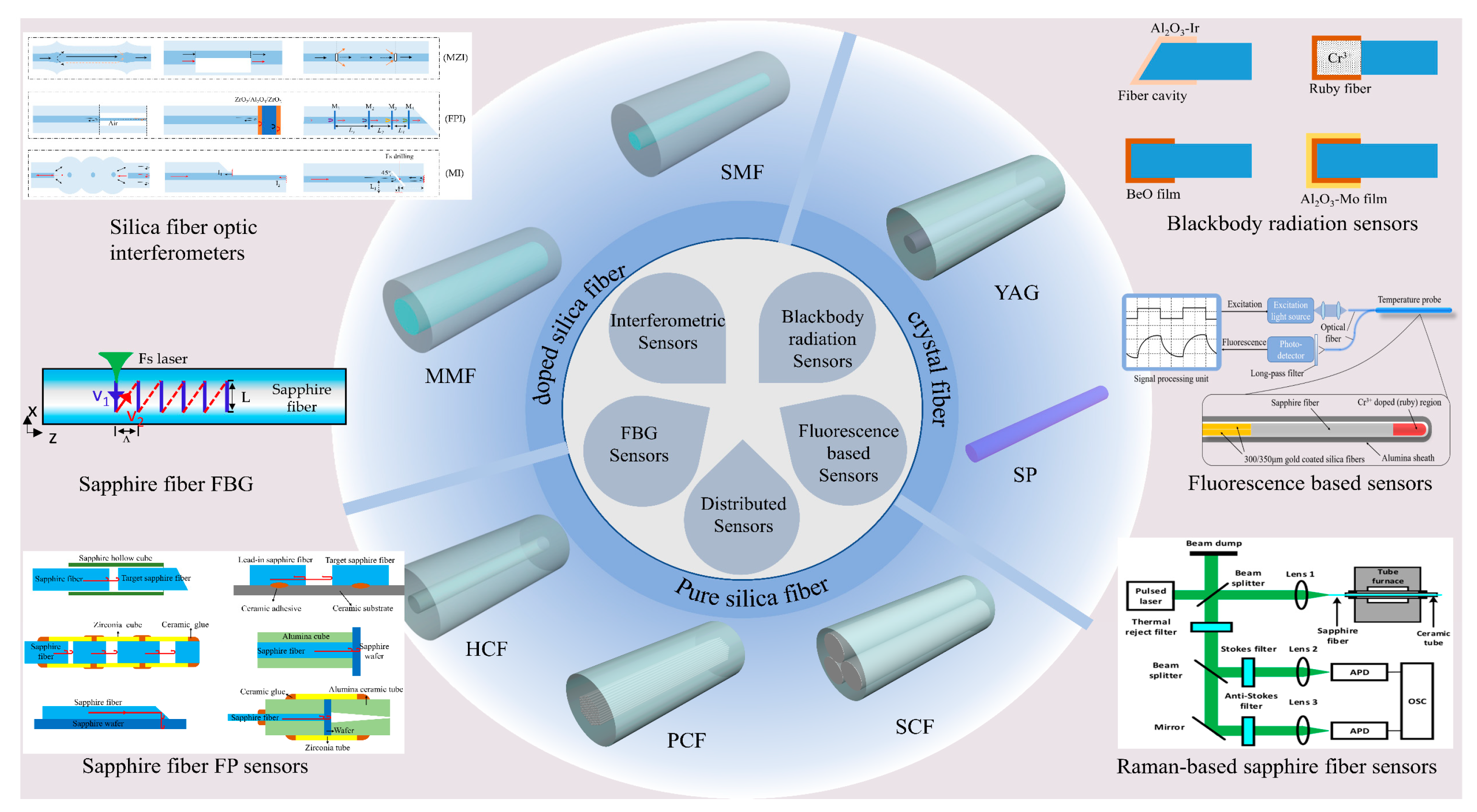
1. Introduction
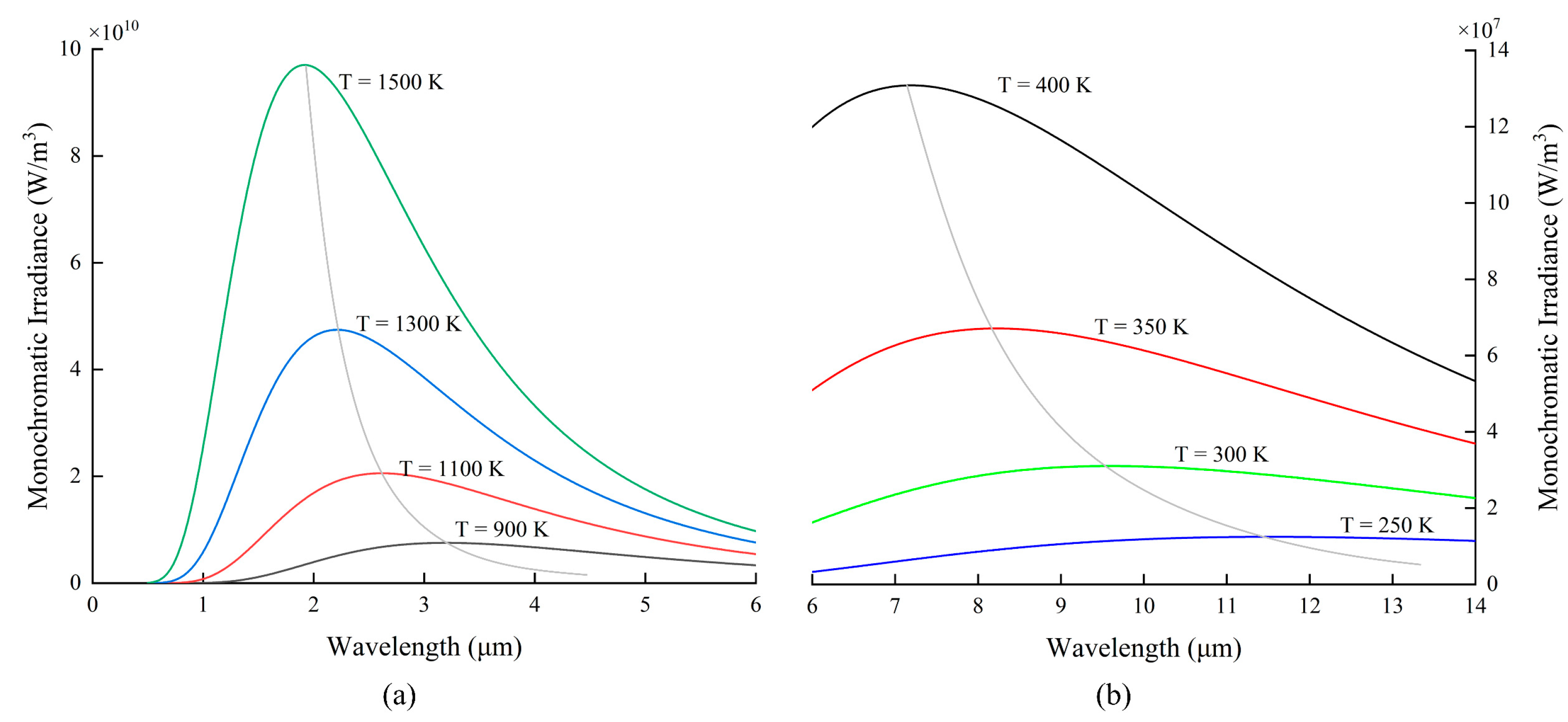
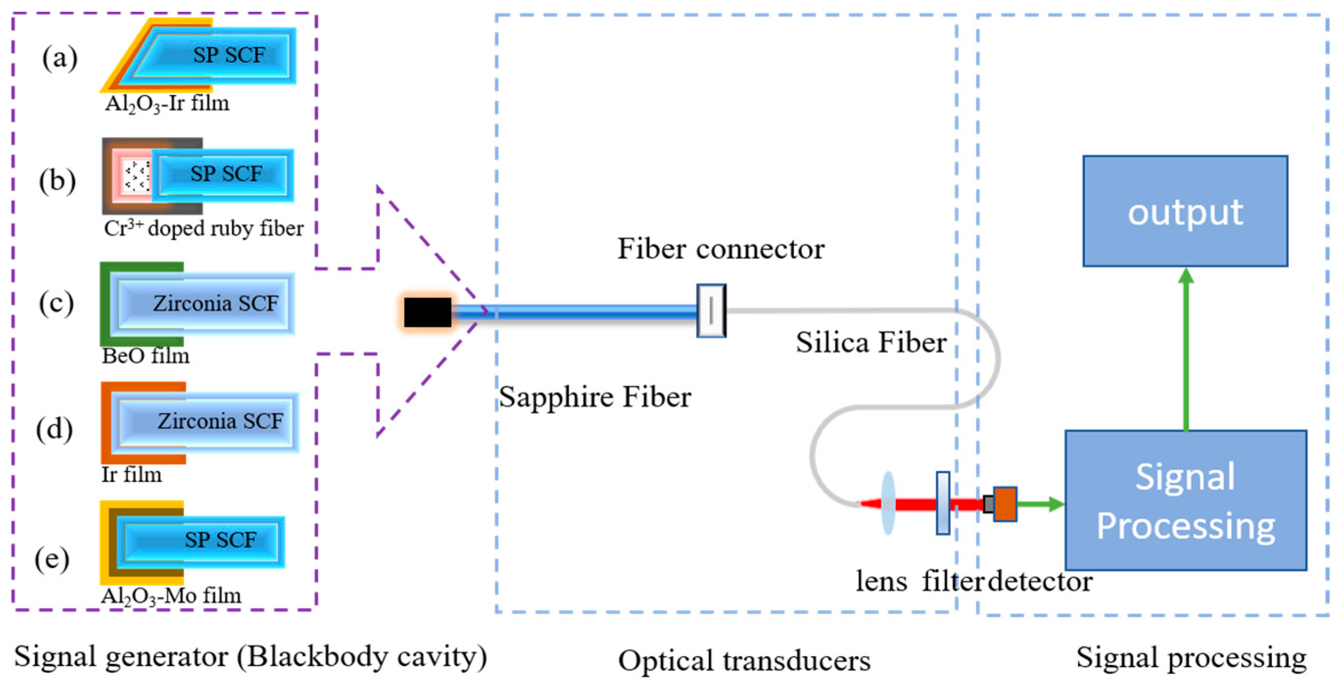
2. Blackbody Radiation Sensors
2.1. Sensing Principle of Blackbody Radiation
2.2. Development of Blackbody OFT
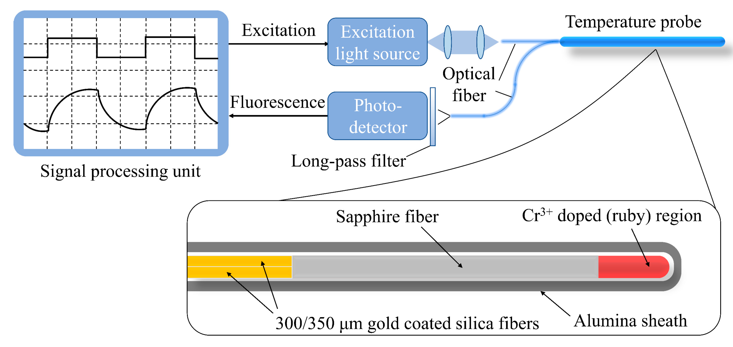
3. Fluorescence-Based Sensors
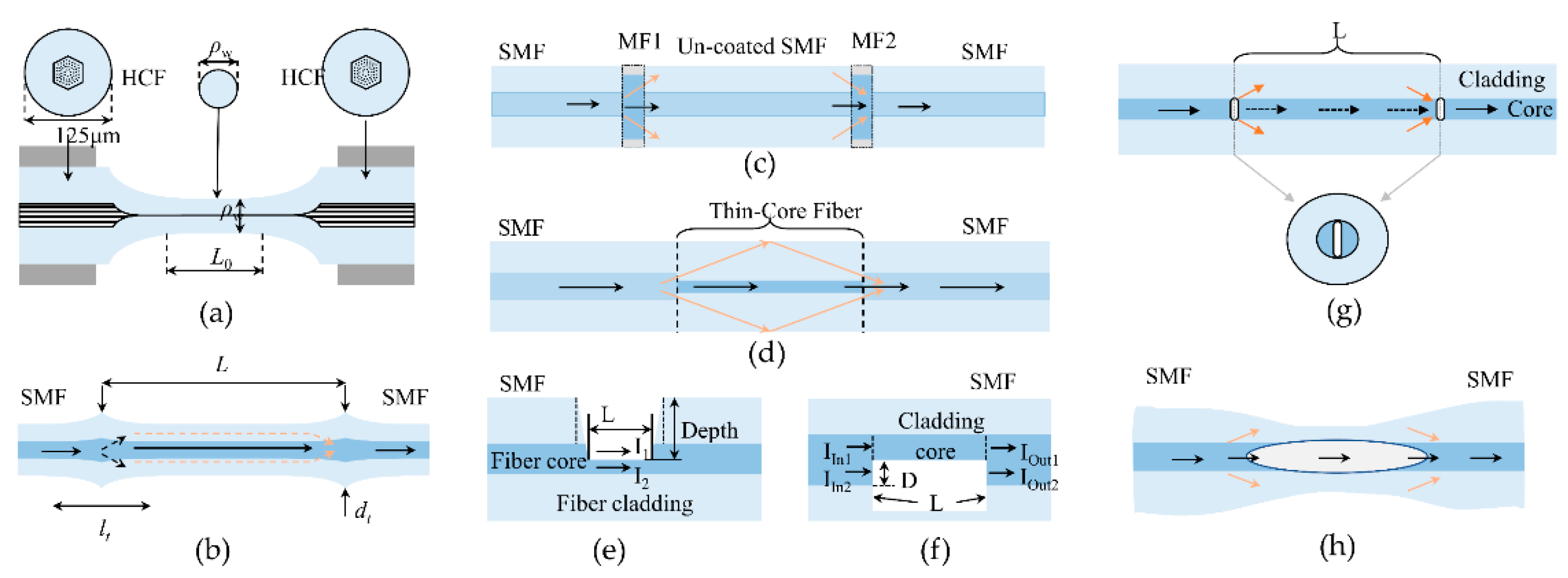
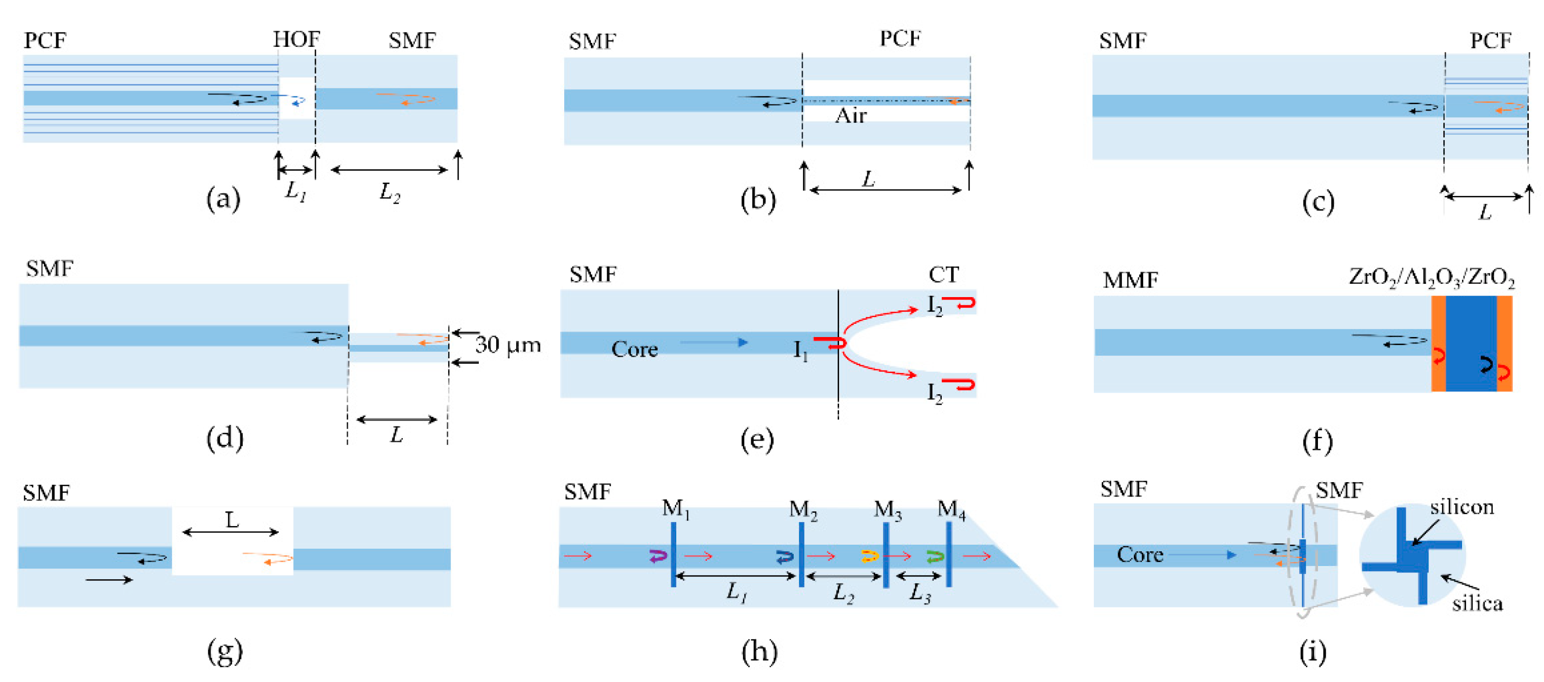
4. Interferometric Sensors
4.1. Silica Fiber-Optic Interferometers for High-Temperature Sensing up to 1000 °C
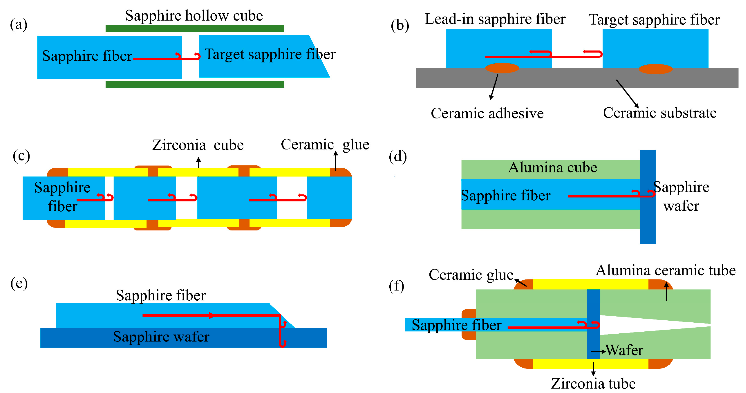
4.2. Sapphire FPI Sensors for High-Temperature Sensing
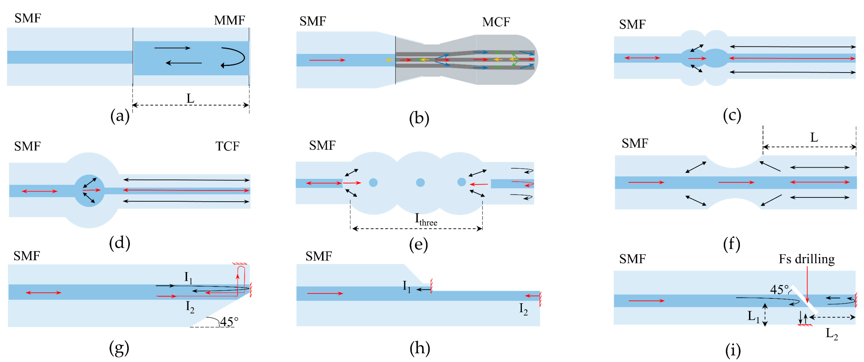
4.3. Sapphire Michelson Interferometric Sensors
5. Fiber Bragg Grating Sensors
5.1. Silica FBGs for High-Temperature Sensing up to 100 °C
5.2. Sapphire FBGs for High-Temperature Sensing up to 2000 °C
5.2.1. Phase Mask Method
5.2.2. Talbot Interferometer
5.2.3. Point-by-Point Inscription
5.2.4. Line-by-Line Inscription
6. Distributed Sensing
6.1. Brillouin Scattering-Based Optical Time-Domain Analysis System
6.2. Raman Scattering-Based OTDR System
6.3. Rayleigh Scattering-Based OFDR System
7. Future Prospects
- The development of new high-temperature-resistant optical fiber. The high-temperature resistance of optical fiber is the key to improving the temperature range of the sensor; the preparation of high-quality optical fiber with a high melting point, low loss, strong oxidation resistance, and excellent mechanical properties will greatly promote the development of the high-temperature detection field.
- Adding cladding to crystal fiber. The lack of a durable cladding limits the sensing performance and long-term stability of crystal fiber sensors. Despite the wide range of crystal fiber cladding materials that have been developed [166], the development and commercialization of crystal fiber cladding remain challenging.
- Crystal fiber single-mode development. Tapered fiber coupling [152], diameter reduction [159,204], offset coupling [163], and other methods [154], to some extent, overcome the shortcomings of crystal fiber multimode but are less suitable for industrial applications. Radiation [201] or inscribed helical stripes [205] are expected to produce cladding inside the fiber to improve the stability and practicality of the sensor.
- Multi-parameter measurement. In practice, high-temperature extreme environments are often accompanied by complex state changes. The development of sensors with simultaneous measurement of multiple parameters such as temperature, strain, pressure, and radiation is essential.
- Long-term stability and package protection. High-temperature sensors are constantly facing the test of high temperature, high pressure, strong radiation, strong corrosion, and other harsh environments, so good package protection to improve the life of the sensor is the goal of the future.
8. Conclusions
Author Contributions
Funding
Institutional Review Board Statement
Informed Consent Statement
Data Availability Statement
Conflicts of Interest
References
- Yang, S.; Homa, D.; Heyl, H.; Theis, L.; Beach, J.; Dudding, B.; Acord, G.; Taylor, D.; Pickrell, G.; Wang, A. Application of sapphire-fiber-bragg-grating-based multi-point temperature sensor in boilers at a commercial power plant. Sensors 2019, 19, 3211. [Google Scholar] [CrossRef] [PubMed]
- Watson, J.; Castro, G. A review of high-temperature electronics technology and applications. J. Mater. Sci. Mater. Electron. 2015, 26, 9226–9235. [Google Scholar] [CrossRef]
- Childs, P.R.N.; Greenwood, J.R.; Long, C.A. Review of temperature measurement. Rev. Sci. Instrum. 2000, 71, 2959–2978. [Google Scholar] [CrossRef]
- Rizzolo, S.; Périsse, J.; Boukenter, A.; Ouerdane, Y.; Marin, E.; Macé, J.-R.; Cannas, M.; Girard, S. Real time monitoring of water level and temperature in storage fuel pools through optical fibre sensors. Sci. Rep. 2017, 7, 8766. [Google Scholar] [CrossRef] [PubMed]
- Sang, A.K.; Froggatt, M.E.; Gifford, D.K.; Kreger, S.T.; Dickerson, B.D. One centimeter spatial resolution temperature measurements in a nuclear reactor using rayleigh scatter in optical fiber. IEEE Sens. J. 2008, 8, 1375–1380. [Google Scholar] [CrossRef]
- Reinsch, T.; Henninges, J. Temperature-dependent characterization of optical fibres for distributed temperature sensing in hot geothermal wells. Meas. Sci. Technol. 2010, 21, 94022. [Google Scholar] [CrossRef]
- Lu, P.; Lalam, N.; Badar, M.; Liu, B.; Chorpening, B.T.; Buric, M.P.; Ohodnicki, P.R. Distributed Optical Fiber Sensing: Review and Perspective. Appl. Phys. Rev. 2019, 6, 041302. [Google Scholar] [CrossRef]
- Willsch, M.; Bosselmann, T.; Flohr, P.; Kull, R.; Ecke, W.; Latka, I.; Fischer, D.; Thiel, T. Design of Fiber Optical High Temperature Sensors for Gas Turbine Monitoring; Jones, J.D.C., Ed.; SPIE: Bellingham, WA, USA, 2009; p. 75037R. [Google Scholar]
- Mekhrengin, M.V.; Meshkovskii, I.K.; Tashkinov, V.A.; Guryev, V.I.; Sukhinets, A.V.; Smirnov, D.S. Multispectral pyrometer for high temperature measurements inside combustion chamber of gas turbine engines. Measurement 2019, 139, 355–360. [Google Scholar] [CrossRef]
- García, I.; Zubia, J.; Durana, G.; Aldabaldetreku, G.; Illarramendi, M.; Villatoro, J. Optical fiber sensors for aircraft structural health monitoring. Sensors 2015, 15, 15494–15519. [Google Scholar] [CrossRef] [PubMed]
- Gao, S.; Wang, L.; Feng, C. Multi-Spectral Pyrometer for Gas Turbine Blade Temperature Measurement; Kazemi, A.A., Kress, B.C., Mendoza, E.A., Eds.; SPIE: Bellingham, WA, USA, 2014; p. 920217. [Google Scholar]
- Liang, M.; Sun, B.; Sun, X.; Xie, J. Development of a new fiber-optic multi-target multispectral pyrometer for achievable true temperature measurement of the solid rocket motor plume. Measurement 2017, 95, 239–245. [Google Scholar] [CrossRef]
- Usamentiaga, R.; Venegas, P.; Guerediaga, J.; Vega, L.; Molleda, J.; Bulnes, F. Infrared thermography for temperature measurement and non-destructive testing. Sensors 2014, 14, 12305–12348. [Google Scholar] [CrossRef]
- Bradley, D.; Matthews, K.J. Measurement of high gas temperatures with fine wire thermocouples. J. Mech. Eng. Sci. 1968, 10, 299–305. [Google Scholar] [CrossRef]
- Heitor, M.V.; Moreira, A.L.N. Thermocouples and sample probes for combustion studies. Prog. Energy Combust. Sci. 1993, 19, 259–278. [Google Scholar] [CrossRef]
- Kus, A.; Isik, Y.; Cakir, M.C.; Co, S. Thermocouple and infrared sensor-based measurement of temperature distribution in metal cutting. Sensors 2015, 15, 1274. [Google Scholar] [CrossRef] [PubMed]
- Jun, S.; Kochan, O. Investigations of Thermocouple drift irregularity impact on error of their inhomogeneity correction. Meas. Sci. Rev. 2014, 14, 29–34. [Google Scholar] [CrossRef]
- Holmsten, M.; Ivarsson, J.; Falk, R.; Lidbeck, M.; Josefson, L.-E. Inhomogeneity measurements of long thermocouples using a short movable heating zone. Int. J. Thermophys. 2008, 29, 915–925. [Google Scholar] [CrossRef]
- Nie, B.; He, X.; Zhang, C.; Li, X.; Li, H. Temperature measurement of gas explosion flame based on the radiation thermometry. Int. J. Therm. Sci. 2014, 78, 132–144. [Google Scholar] [CrossRef]
- Meriaudeau, F. Real time multispectral high temperature measurement: Application to control in the industry. Image Vis. Comput. 2007, 25, 1124–1133. [Google Scholar] [CrossRef]
- Hartmann, J. High-temperature measurement techniques for the application in photometry, radiometry and thermometry. Phys. Rep. 2009, 469, 205–269. [Google Scholar] [CrossRef]
- Lou, C.; Li, W.-H.; Zhou, H.-C.; Salinas, C.T. Experimental investigation on simultaneous measurement of temperature distributions and radiative properties in an oil-fired tunnel furnace by radiation analysis. Int. J. Heat Mass Transf. 2011, 54, 1–8. [Google Scholar] [CrossRef]
- Roriz, P.; Silva, S.; Frazão, O.; Novais, S. Optical fiber temperature sensors and their biomedical applications. Sensors 2020, 20, 2113. [Google Scholar] [CrossRef]
- Mihailov, S.J. Fiber bragg grating sensors for harsh environments. Sensors 2012, 12, 1898–1918. [Google Scholar] [CrossRef]
- Joe, H.-E.; Yun, H.; Jo, S.-H.; Jun, M.B.G.; Min, B.-K. A Review on Optical Fiber Sensors for Environmental Monitoring. Int. J. Precis. Eng. Manuf.-Green Tech. 2018, 5, 173–191. [Google Scholar] [CrossRef]
- Xu, Y.; Lu, P.; Chen, L.; Bao, X. Recent developments in micro-structured fiber optic sensors. Fibers 2017, 5, 3. [Google Scholar] [CrossRef]
- Yu, Y.B.; Chow, W.K. Review on an advanced high-temperature measurement technology: The optical fiber thermometry. J. Thermodyn. 2009, 2009, 823482. [Google Scholar] [CrossRef]
- Wang, B.; Niu, Y.; Qin, X.; Yin, Y.; Ding, M. Review of high temperature measurement technology based on sapphire optical fiber. Measurement 2021, 184, 109868. [Google Scholar] [CrossRef]
- Müller, B.; Renz, U. Development of a fast fiber-optic two-color pyrometer for the temperature measurement of surfaces with varying emissivities. Rev. Sci. Instrum. 2001, 72, 3366–3374. [Google Scholar] [CrossRef]
- Shen, Y.; Tong, L.; Wang, Y.; Ye, L. Sapphire-fiber thermometer ranging from 20 to 1800 °C. Appl. Opt. 1999, 38, 1139. [Google Scholar] [CrossRef] [PubMed]
- Dils, R.R. High-temperature optical fiber thermometer. J. Appl. Phys. 1983, 54, 1198–1201. [Google Scholar] [CrossRef]
- Reiser, A.; Schächter, L. Geometric effects on blackbody radiation. Phys. Rev. A 2013, 87, 33801. [Google Scholar] [CrossRef]
- Gottlieb, M.; Brandt, G.B. Fiber-optic temperature sensor based on internally generated thermal radiation. Appl. Opt. 1981, 20, 3408. [Google Scholar] [CrossRef]
- Barker, D.G.; Jones, M.R. Temperature measurements using a high-temperature blackbody optical fiber thermometer. J. Heat Transf. 2003, 125, 471–477. [Google Scholar] [CrossRef]
- Grattan, K.T.V.; Palmer, A.W.; Zhang, Z. Development of a high-temperature fiber-optic thermometer probe using fluorescent decay. Rev. Sci. Instrum. 1991, 62, 1210–1213. [Google Scholar] [CrossRef]
- Zhang, Z.Y.; Grattan, K.T.V.; Meggitt, B.T. Thulium-doped fiber optic decay-time temperature sensors: Characterization of high temperature performance. Rev. Sci. Instrum. 2000, 71, 1614–1620. [Google Scholar] [CrossRef]
- Tong, L.; Shen, Y.; Ye, L.; Ding, Z. A zirconia single-crystal fibre-optic sensor for contact measurement of temperatures above 2000 °C. Meas. Sci. Technol. 1999, 10, 607. [Google Scholar] [CrossRef]
- Wei, W.; Xiaotian, S.; Ying, W. Sapphire fiber-optic temperature sensor based on black-body radiation law. Procedia Eng. 2015, 99, 1179–1184. [Google Scholar] [CrossRef]
- Guo, Y.; Xia, W.; Hu, Z.; Wang, M. High-temperature sensor instrumentation with a thin-film-based sapphire fiber. Appl. Opt. 2017, 56, 2068. [Google Scholar] [CrossRef] [PubMed]
- Mihailov, S.J.; Grobnic, D.; Smelser, C.W. High-temperature multiparameter sensor based on sapphire fiber bragg gratings. Opt. Lett. 2010, 35, 2810. [Google Scholar] [CrossRef] [PubMed]
- Tian, Z.; Yu, Z.; Liu, B.; Wang, A. Sourceless optical fiber high temperature sensor. Opt. Lett. 2016, 41, 195. [Google Scholar] [CrossRef] [PubMed]
- Jones, M.R.; Barker, D.G. Use of blackbody optical fiber thermometers in high-temperature environments. J. Thermophys. Heat Transf. 2002, 16, 306–312. [Google Scholar] [CrossRef]
- Lei, X.; Xie, L.; Qi, L.; Chen, W. Coupling efficiency of light intensity from the blackbody cavity into a cone-shaped optical fiber. Appl. Opt. 2019, 58, 1707. [Google Scholar] [CrossRef] [PubMed]
- Chen, Y.; Lei, X.; Xie, L.; Chen, T.; Liu, X.; Zhang, P.; Zhu, Y. Correlation-like demodulation of fiber fabry–perot sensor based on blackbody radiation light source. IEEE Sens. J. 2021, 21, 9063–9071. [Google Scholar] [CrossRef]
- Grattan, K.T.V.; Zhang, Z.Y.; Sun, T.; Shen, Y.; Tong, L.; Ding, Z. Sapphire–ruby single-crystal fibre for application in high temperature optical fibre thermometers—Studies at Temperatures up to 1500 °C. Meas. Sci. Technol. 2001, 12, 981. [Google Scholar]
- Shen, Y.; Zhao, W.; He, J.; Sun, T.; Grattan, K.T.V. Fluorescence decay characteristic of Tm-Doped YAG crystal fiber for sensor applications, investigated from room temperature to 1400 °C. IEEE Sens. J. 2003, 3, 507–512. [Google Scholar] [CrossRef]
- Wade, S.A.; Collins, S.F.; Baxter, G.W. Fluorescence intensity ratio technique for optical fiber point temperature sensing. J. Appl. Phys. 2003, 94, 4743. [Google Scholar] [CrossRef]
- Rai, V.K. Temperature sensors and optical sensors. Appl. Phys. B 2007, 88, 297–303. [Google Scholar] [CrossRef]
- Ye, L.; Zhang, J.; Shi, Y. Growth and characteristics of Cr3+:YAG crystal fiber for fluorescence decay temperature sensor. Rev. Sci. Instrum. 2006, 77, 054901. [Google Scholar] [CrossRef]
- Fernicola, V.; Crovini, L. Digital optical fiber point sensor for high-temperature measurement. J. Lightwave Technol. 1995, 13, 1331–1334. [Google Scholar] [CrossRef]
- Zhang, Z.Y.; Grattan, K.T.V.; Palmer, A.W.; Meggitt, B.T. Potential for temperature sensor applications of highly neodymium-doped crystals and fiber at up to approximately 1000 °C. Rev. Sci. Instrum. 1997, 68, 2759–2763. [Google Scholar] [CrossRef]
- Kennedy, J.L.; Djeu, N. Operation of Yb: YAG fiber-optic temperature sensor up to 1600 °C. Sens. Actuators A Phys. 2002, 100, 187–191. [Google Scholar] [CrossRef]
- Skinner, S.J.; Feist, J.P.; Brooks, I.J.E.; Seefeldt, S.; Heyes, A.L. YAG: YSZ composites as potential thermographic phosphors for high temperature sensor applications. Sens. Actuators B Chem. 2009, 136, 52–59. [Google Scholar] [CrossRef]
- Allison, S.W.; Beshears, D.L.; Cates, M.R.; Scudiere, M.B.; Shaw, D.W.; Ellis, A.D. Luminescence of YAG:Dy and YAG:Dy,Er crystals to 1700 °C. Meas. Sci. Technol. 2020, 31, 044001. [Google Scholar] [CrossRef]
- Aizawa, H.; Katsumata, T.; Komuro, S.; Morikawa, T.; Ishizawa, H.; Toba, E. Fluorescence thermometer based on the photoluminescence intensity ratio in Tb doped phosphor materials. Sens. Actuators A Phys. 2006, 126, 78–82. [Google Scholar] [CrossRef]
- Hu, S.; Lu, C.; Liu, X.; Xu, Z. Optical temperature sensing based on the luminescence from YAG:Pr transparent ceramics. Opt. Mater. 2016, 60, 394–397. [Google Scholar] [CrossRef]
- Demirkhanyan, H.G.; Demirkhanyan, G.G.; Kostanyan, R.B. YAG:Yb 3+ Crystal as a potential material for optical temperature sensors. Laser Phys. 2018, 28, 025701. [Google Scholar] [CrossRef]
- Zhu, K.; Zhou, H.; Qiu, J.; Wang, L.-G.; Ye, L. Optical temperature sensing characteristics of Sm3+ doped YAG single crystal fiber based on luminescence emission. J. Alloy. Compd. 2022, 890, 161844. [Google Scholar] [CrossRef]
- Sholes, R.R.; Small, J.G. Fluorescent decay thermometer with biological applications. Rev. Sci. Instrum. 1980, 51, 882–884. [Google Scholar] [CrossRef]
- Zhang, Z.; Grattan, K.T.V.; Palmer, A.W. Fiber optic temperature sensor based on the cross referencing between blackbody radiation and fluorescence lifetime. Rev. Sci. Instrum. 1992, 63, 3177–3181. [Google Scholar] [CrossRef]
- Zhang, Z.Y.; Grattan, K.T.V.; Palmer, A.W.; Meggitt, B.T.; Sun, T. Fluorescence decay-time characteristics of erbium-doped optical fiber at elevated temperatures. Rev. Sci. Instrum. 1997, 68, 2764–2766. [Google Scholar] [CrossRef]
- Zhang, Z.Y. Optical fiber temperature sensor scheme using Tm-doped yttrium oxide powder-based probe. In Proceedings of the 13th International Conference on Optical Fiber Sensors; SPIE: Kyongju, Korea, 1999; p. 76. [Google Scholar]
- Lee, B.H.; Kim, Y.H.; Park, K.S.; Eom, J.B.; Kim, M.J.; Rho, B.S.; Choi, H.Y. Interferometric fiber optic sensors. Sensors 2012, 12, 2467–2486. [Google Scholar] [CrossRef] [PubMed]
- Shen, F.; Wang, A. Frequency-estimation-based signal-processing algorithm for white-light optical fiber fabry–perot interferometers. Appl. Opt. 2005, 44, 5206. [Google Scholar] [CrossRef]
- Ma, C.; Lally, E.M.; Wang, A. Toward eliminating signal demodulation jumps in optical fiber intrinsic fabry—Perot interferometric sensors. J. Lightwave Technol. 2011, 29, 1913–1919. [Google Scholar] [CrossRef]
- Polyzos, D.; Mathew, J.; MacPherson, W.N.; Maier, R.R.J. Effect of dopant diffusion on the long-term stability of fabry—Pérot optical fiber sensors. J. Lightwave Technol. 2017, 35, 5317–5323. [Google Scholar] [CrossRef]
- Rose, A.H.; Bruno, T.J. The observation of OH in annealed optical fiber. J. Non-cryst. Solids. 1998, 231, 280–285. [Google Scholar] [CrossRef]
- Zhu, T.; Wu, D.; Liu, M.; Duan, D.-W. In-Line fiber optic interferometric sensors in single-mode fibers. Sensors 2012, 12, 10430–10449. [Google Scholar] [CrossRef] [PubMed]
- Monzon-Hernandez, D.; Minkovich, V.P.; Villatoro, J. High-temperature sensing with tapers made of microstructured optical fiber. IEEE Photon. Technol. Lett. 2006, 18, 511–513. [Google Scholar] [CrossRef]
- Geng, Y.; Li, X.; Tan, X.; Deng, Y.; Yu, Y. High-sensitivity mach–zehnder interferometric temperature fiber sensor based on a waist-enlarged fusion bitaper. IEEE Sens. J. 2011, 11, 2891–2894. [Google Scholar] [CrossRef]
- Viet Nguyen, L.; Hwang, D.; Moon, S.; Seung Moon, D.; Chung, Y. High temperature fiber sensor with high sensitivity based on core diameter mismatch. Opt. Express 2008, 16, 11369. [Google Scholar] [CrossRef]
- Zhu, J.-J.; Zhang, A.P.; Xia, T.-H.; He, S.; Xue, W. Fiber-optic high-temperature sensor based on thin-core fiber modal interferometer. IEEE Sens. J. 2010, 10, 1415–1418. [Google Scholar] [CrossRef]
- Zhao, L.; Jiang, L.; Wang, S.; Xiao, H.; Lu, Y.; Tsai, H.-L. A High-quality mach-zehnder interferometer fiber sensor by femtosecond laser one-step processing. Sensors 2010, 11, 54–61. [Google Scholar] [CrossRef]
- Wang, Y.; Li, Y.; Liao, C.; Wang, D.N.; Yang, M.; Lu, P. High-temperature sensing using miniaturized fiber in-line mach–zehnder interferometer. IEEE Photon. Technol. Lett. 2010, 22, 39–41. [Google Scholar] [CrossRef]
- Jiang, L.; Yang, J.; Wang, S.; Li, B.; Wang, M. Fiber mach–zehnder interferometer based on microcavities for high-temperature sensing with high sensitivity. Opt. Lett. 2011, 36, 3753. [Google Scholar] [CrossRef] [PubMed]
- Liao, C.R.; Chen, H.F.; Wang, D.N. Ultracompact Optical Fiber Sensor for Refractive Index and High-Temperature Measurement. J. Lightwave Technol. 2014, 32, 2531–2535. [Google Scholar] [CrossRef]
- Choi, H.Y.; Park, K.S.; Park, S.J.; Paek, U.-C.; Lee, B.H.; Choi, E.S. Miniature fiber-optic high temperature sensor based on a hybrid structured fabry–perot interferometer. Opt. Lett. 2008, 33, 2455. [Google Scholar] [CrossRef]
- Zhu, T.; Ke, T.; Rao, Y.; Chiang, K.S. Fabry–perot optical fiber tip sensor for high temperature measurement. Opt. Commun. 2010, 283, 3683–3685. [Google Scholar] [CrossRef]
- Ding, W.; Jiang, Y.; Gao, R.; Liu, Y. High-temperature fiber-optic fabry-perot interferometric sensors. Rev. Sci. Instrum. 2015, 86, 55001. [Google Scholar] [CrossRef] [PubMed]
- Chen, Z.; Xiong, S.; Gao, S.; Zhang, H.; Wan, L.; Huang, X.; Huang, B.; Feng, Y.; Liu, W.; Li, Z. High-temperature sensor based on fabry-perot interferometer in microfiber tip. Sensors 2018, 18, 202. [Google Scholar] [CrossRef]
- Zhu, C.; Zhuang, Y.; Zhang, B.; Muhammad, R.; Wang, P.P.; Huang, J. A Miniaturized optical fiber tip high-temperature sensor based on concave-shaped fabry–perot cavity. IEEE Photon. Technol. Lett. 2019, 31, 35–38. [Google Scholar] [CrossRef]
- Lee, D.; Yang, M.; Huang, C.; Dai, J. Optical fiber high-temperature sensor based on dielectric films extrinsic fabry–pérot cavity. IEEE Photon. Technol. Lett. 2014, 26, 2107–2110. [Google Scholar] [CrossRef]
- Wei, T.; Han, Y.; Tsai, H.-L.; Xiao, H. Miniaturized fiber inline fabry-perot interferometer fabricated with a femtosecond laser. Opt. Lett. 2008, 33, 536. [Google Scholar] [CrossRef] [PubMed]
- Deng, J.; Wang, D.N. Construction of cascaded fabry–perot interferometers by four in-fiber mirrors for high-temperature sensing. Opt. Lett. 2019, 44, 1289. [Google Scholar] [CrossRef] [PubMed]
- Deng, J.; Wang, D.N.; Zhang, H. Femtosecond laser inscribed multiple in-fiber reflection mirrors for high-temperature sensing. J. Lightwave Technol. 2019, 37, 5537–5541. [Google Scholar] [CrossRef]
- Micco, A.; Ricciardi, A.; Quero, G.; Crescitelli, A.; Bock, W.J.; Cusano, A. Simple technique for integrating compact silicon devices within optical fibers. Opt. Lett. 2014, 39, 861. [Google Scholar] [CrossRef] [PubMed]
- Chen, P.; Shu, X. Refractive-index-modified-dot fabry-perot fiber probe fabricated by femtosecond laser for high-temperature sensing. Opt. Express 2018, 26, 5292. [Google Scholar] [CrossRef] [PubMed]
- Li, E.; Wang, X.; Zhang, C. Fiber-optic temperature sensor based on interference of selective higher-order modes. Appl. Phys. Lett. 2006, 89, 91119. [Google Scholar] [CrossRef]
- Li, E. Temperature compensation of multimode-interference-based fiber devices. Opt. Lett. 2007, 32, 2064. [Google Scholar] [CrossRef] [PubMed]
- Dong, B.; Wei, L.; Zhou, D.-P. Miniature high-sensitivity high-temperature fiber sensor with a dispersion compensation fiber-based interferometer. Appl. Opt. 2009, 48, 6466. [Google Scholar] [CrossRef]
- Duan, L.; Zhang, P.; Tang, M.; Wang, R.; Zhao, Z.; Fu, S.; Gan, L.; Zhu, B.; Tong, W.; Liu, D.; et al. Heterogeneous all-solid multicore fiber based multipath Michelson interferometer for high temperature sensing. Opt. Express 2016, 24, 20210. [Google Scholar] [CrossRef] [PubMed]
- Wu, D.; Zhu, T.; Liu, M. A High temperature sensor based on a peanut-shape structure Michelson interferometer. Opt. Commun. 2012, 285, 5085–5088. [Google Scholar] [CrossRef]
- Xu, L.; Jiang, L.; Wang, S.; Li, B.; Lu, Y. High-temperature sensor based on an abrupt-taper Michelson interferometer in single-mode fiber. Appl. Opt. 2013, 52, 2038. [Google Scholar] [CrossRef] [PubMed]
- Zhao, N.; Fu, H.; Shao, M.; Yan, X.; Li, H.; Liu, Q.; Gao, H.; Liu, Y.; Qiao, X. High temperature probe sensor with high sensitivity based on Michelson interferometer. Opt. Commun. 2015, 343, 131–134. [Google Scholar] [CrossRef]
- Cao, H.; Shu, X. Miniature all-fiber high temperature sensor based on Michelson interferometer formed with a novel core-mismatching fiber joint. IEEE Sens. J. 2017, 17, 3341–3345. [Google Scholar] [CrossRef]
- Qi, K.; Zhang, Y.; Sun, J.; Yi, G. All-fiber high temperature and refractive index sensor based on three microspheres array michelson interferometer. Opt. Laser Technol. 2020, 129, 106300. [Google Scholar] [CrossRef]
- Han, Y.; Liu, B.; Wu, Y.; Mao, Y.; Zhao, L.; Nan, T.; Wang, J.; Zhang, Y.; Tang, R.; Liu, Y.; et al. High-sensitivity high-temperature sensor based on multi-microspheres improved Michelson interferometer. Opt. Commun. 2021, 491, 126932. [Google Scholar] [CrossRef]
- Guo, J.; Lian, S.; Zhang, Y.; Zhang, Y.; Liang, D.; Yu, Y.; Chen, R.; Du, C.; Ruan, S. High-temperature measurement of a fiber probe sensor based on the Michelson interferometer. Sensors 2021, 22, 289. [Google Scholar] [CrossRef] [PubMed]
- Han, Y.; Liu, B.; Wu, Y.; Mao, Y.; Wu, J.; Zhao, L.; Nan, T.; Wang, J.; Tang, R.; Zhang, Y.; et al. Ultra-compact silicon-microcap based improved Michelson interferometer high-temperature sensor. Opt. Express 2021, 29, 6703. [Google Scholar] [CrossRef]
- Yin, J.; Liu, T.; Jiang, J.; Liu, K.; Wang, S.; Zou, S.; Wu, F. Assembly-free-based fiber-optic micro-Michelson interferometer for high temperature sensing. IEEE Photon. Technol. Lett. 2016, 28, 625–628. [Google Scholar] [CrossRef]
- Yuan, L.; Wei, T.; Han, Q.; Wang, H.; Huang, J.; Jiang, L.; Xiao, H. Fiber inline Michelson interferometer fabricated by a femtosecond laser. Opt. Lett. 2012, 37, 4489. [Google Scholar] [CrossRef]
- Liu, Y.; Wang, D.N. Fiber in-line Michelson interferometer based on inclined narrow slit crossing the fiber core. IEEE Photon. Technol. Lett. 2018, 30, 293–296. [Google Scholar] [CrossRef]
- Nubling, R.K.; Harrington, J.A. Optical Properties of single-crystal sapphire fibers. Appl. Opt. 1997, 36, 5934. [Google Scholar] [CrossRef]
- Wang, A.; Gollapudi, S.; Murphy, K.A.; May, G. Sapphire-fiber-based intrinsic fabry-perot interferometer. Opt. Lett. 1992, 17, 3. [Google Scholar] [CrossRef] [PubMed]
- Wang, A.; Gollapudi, S.; May, R.G.; Murphy, K.A.; Claus, R.O. Advances in sapphire-fiber-based intrinsic interferometric sensors. Opt. Lett. 1992, 17, 1544. [Google Scholar] [CrossRef] [PubMed]
- Wang, A.; Gollapudi, S.; May, R.G.; Murphy, K.A.; Claus, R.O. Sapphire optical fiber-based interferometer for high temperature environmental applications. Smart Mater. Struct. 1995, 4, 147–151. [Google Scholar] [CrossRef]
- Xiao, H.; Deng, J.; Pickrell, G.; May, R.G. Anbo Wang single-crystal sapphire fiber-based strain sensor for high-temperature applications. J. Lightwave Technol. 2003, 21, 2276–2283. [Google Scholar] [CrossRef]
- Wang, J.; Dong, B.; Lally, E.; Gong, J.; Han, M.; Wang, A. Multiplexed high temperature sensing with sapphire fiber air gap-based extrinsic fabry–perot interferometers. Opt. Lett. 2010, 35, 619. [Google Scholar] [CrossRef]
- Zhu, Y.; Huang, Z.; Shen, F.; Wang, A. Sapphire-fiber-based white-light interferometric sensor for high-temperature measurements. Opt. Lett. 2005, 30, 711. [Google Scholar] [CrossRef]
- Zhu, Y.; Wang, A. Surface-mount sapphire interferometric temperature sensor. Appl. Opt. 2006, 45, 6071. [Google Scholar] [CrossRef]
- Li, W.; Liang, T.; Chen, Y.; Jia, P.; Xiong, J.; Hong, Y.; Lei, C.; Yao, Z.; Qi, L.; Liu, W. Interface characteristics of sapphire direct bonding for high-temperature applications. Sensors 2017, 17, 2080. [Google Scholar] [CrossRef] [PubMed]
- Li, W.; Liang, T.; Jia, P.; Lei, C.; Hong, Y.; Li, Y.; Yao, Z.; Liu, W.; Xiong, J. Fiber-optic fabry–perot pressure sensor based on sapphire direct bonding for high-temperature applications. Appl. Opt. 2019, 58, 1662. [Google Scholar] [CrossRef]
- Wang, J.; Lally, E.M.; Dong, B.; Gong, J. Anbo wang fabrication of a miniaturized thin-film temperature sensor on a sapphire fiber tip. IEEE Sensors J. 2011, 11, 3406–3408. [Google Scholar] [CrossRef]
- Wang, J.; Lally, E.M.; Wang, X.; Gong, J.; Pickrell, G.; Wang, A. ZrO2 thin-film-based sapphire fiber temperature sensor. Appl. Opt. 2012, 51, 2129. [Google Scholar] [CrossRef][Green Version]
- Huang, C.; Lee, D.; Dai, J.; Xie, W.; Yang, M. Fabrication of high-temperature temperature sensor based on dielectric multilayer film on sapphire fiber tip. Sens. Actuators A Phys. 2015, 232, 99–102. [Google Scholar] [CrossRef]
- Lee, D.; Tian, Z.; Dai, J.; Hu, W.; Yang, M. Sapphire fiber high-temperature tip sensor with multilayer coating. IEEE Photon. Technol. Lett. 2015, 27, 741–743. [Google Scholar] [CrossRef]
- Wang, B.; Niu, Y.; Zheng, S.; Yin, Y.; Ding, M. A High temperature sensor based on sapphire fiber fabry-perot interferometer. IEEE Photon. Technol. Lett. 2020, 32, 89–92. [Google Scholar] [CrossRef]
- Yang, S.; Feng, Z.; Jia, X.; Pickrell, G.; Ng, W.; Wang, A.; Zhu, Y. All-sapphire miniature optical fiber tip sensor for high temperature measurement. J. Lightwave Technol. 2020, 38, 1988–1997. [Google Scholar] [CrossRef]
- Lin, C.; Steckl, A.J.; Scofield, J. SiC thin-film fabry-perot interferometer for fiber-optic temperature sensor. IEEE Trans. Electron. Devices 2003, 50, 2159–2164. [Google Scholar] [CrossRef]
- Yu, X.; Wang, S.; Jiang, J.; Liu, K.; Wu, Z.; Liu, T. Self-filtering high-resolution dual-sapphire-fiber-based high-temperature sensor. J. Lightwave Technol. 2019, 37, 1408–1414. [Google Scholar] [CrossRef]
- Pérennès, F.; Beard, P.C.; Mills, T.N. Analysis of a low-finesse fabry–perot sensing interferometer illuminated by a multimode optical fiber. Appl. Opt. 1999, 38, 7026. [Google Scholar] [CrossRef] [PubMed]
- Huang, J.; Lan, X.; Song, Y.; Li, Y.; Hua, L.; Xiao, H. Microwave interrogated sapphire fiber michelson interferometer for high temperature sensing. IEEE Photon. Technol. Lett. 2015, 27, 1398–1401. [Google Scholar] [CrossRef]
- Capmany, J.; Novak, D. Microwave photonics combines two worlds. Nat. Photon. 2007, 1, 319–330. [Google Scholar] [CrossRef]
- Yao, J. Microwave Photonics. J. Lightwave Technol. 2009, 27, 314–335. [Google Scholar] [CrossRef]
- Huang, J.; Lan, X.; Wang, H.; Yuan, L.; Xiao, H. Optical Carrier-Based Microwave Interferometers for Sensing Application; Du, H.H., Pickrell, G., Udd, E., Baldwin, C.S., Benterou, J.J., Wang, A., Eds.; SPIE: Baltimore, MD, USA, 2014; p. 90980H. [Google Scholar]
- Hill, K.O.; Meltz, G. Fiber Bragg Grating Technology Fundamentals and Overview. J. Lightwave Technol. 1997, 15, 1263–1276. [Google Scholar] [CrossRef]
- Canning, J.; Stevenson, M.; Bandyopadhyay, S.; Cook, K. Extreme silica optical fibre gratings. Sensors 2008, 8, 6448–6452. [Google Scholar] [CrossRef] [PubMed]
- Lowder, T.L.; Smith, K.H.; Ipson, B.L.; Hawkins, A.R.; Selfridge, R.H.; Schultz, S.M. High-temperature sensing using surface relief fiber bragg gratings. IEEE Photon. Technol. Lett. 2005, 17, 1926–1928. [Google Scholar] [CrossRef]
- Li, Z.; Liu, S.; Bai, Z.; Fu, C.; Zhang, Y.; Sun, Z.; Liu, X.; Wang, Y. Residual-stress-induced helical long period fiber gratings for sensing applications. Opt. Express 2018, 26, 24114. [Google Scholar] [CrossRef]
- Warren-Smith, S.C.; Nguyen, L.V.; Lang, C.; Ebendorff-Heidepriem, H.; Monro, T.M. Temperature sensing up to 1300°C using suspended-core microstructured optical fibers. Opt. Express 2016, 24, 3714. [Google Scholar] [CrossRef] [PubMed]
- Habisreuther, T.; Elsmann, T.; Pan, Z.; Graf, A.; Willsch, R.; Schmidt, M.A. Sapphire fiber bragg gratings for high temperature and dynamic temperature diagnostics. Appl. Therm. Eng. 2015, 91, 860–865. [Google Scholar] [CrossRef]
- Smelser, C.W.; Mihailov, S.J.; Grobnic, D. Hydrogen loading for fiber grating writing with a femtosecond laser and a phase mask. Opt. Lett. 2004, 29, 2127. [Google Scholar] [CrossRef]
- Smelser, C.W.; Mihailov, S.J.; Grobnic, D. Formation of type I-IR and Type II-IR gratings with an ultrafast IR laser and a phase mask. Opt. Express 2005, 13, 5377. [Google Scholar] [CrossRef]
- Bricchi, E.; Klappauf, B.G.; Kazansky, P.G. Form birefringence and negative index change created by femtosecond direct writing in transparent materials. Opt. Lett. 2004, 29, 119. [Google Scholar] [CrossRef] [PubMed]
- He, J.; Wang, Y.; Liao, C.; Wang, Q.; Yang, K.; Sun, B.; Yin, G.; Liu, S.; Zhou, J.; Zhao, J. Highly birefringent phase-shifted fiber bragg gratings inscribed with femtosecond laser. Opt. Lett. 2015, 40, 2008. [Google Scholar] [CrossRef] [PubMed]
- Li, Y.; Liao, C.R.; Wang, D.N.; Sun, T.; Grattan, K.T.V. Study of spectral and annealing properties of fiber bragg gratings written in H2-Free and H2- Loaded fibers by use of femtosecond laser pulses. Opt. Express 2008, 16, 21239. [Google Scholar] [CrossRef]
- Mihailov, S.J.; Smelser, C.W.; Lu, P.; Walker, R.B.; Grobnic, D.; Ding, H.; Henderson, G.; Unruh, J. Fiber bragg gratings made with a phase mask and 800-Nm femtosecond radiation. Opt. Lett. 2003, 28, 995. [Google Scholar] [CrossRef] [PubMed]
- Dragomir, A.; Nikogosyan, D.N.; Zagorulko, K.A.; Kryukov, P.G.; Dianov, E.M. Inscription of fiber bragg gratings by ultraviolet femtosecond radiation. Opt. Lett. 2003, 28, 2171. [Google Scholar] [CrossRef]
- Martinez, A.; Dubov, M.; Khrushchev, I.; Bennion, I. Direct writing of fibre bragg gratings by femtosecond laser. Electron. Lett. 2004, 40, 1170. [Google Scholar] [CrossRef]
- Mihailov, S.J.; Smelser, C.W.; Grobnic, D.; Walker, R.B.; Lu, P.; Ding, H.; Unruh, J. Bragg Gratings Written in All-SiO2 and Ge-Doped Core Fibers With 800-Nm Femtosecond Radiation and a Phase Mask. J. Lightwave Technol. 2004, 22, 94–100. [Google Scholar] [CrossRef]
- Martinez, A.; Khrushchev, I.Y.; Bennion, I. Thermal properties of fibre bragg gratings inscribed point-by-point by infrared femtosecond laser. Electron. Lett. 2005, 41, 176. [Google Scholar] [CrossRef]
- Groothoff, N.; Canning, J. Enhanced type IIA gratings for high-temperature operation. Opt. Lett. 2004, 29, 2360. [Google Scholar] [CrossRef]
- He, J.; Wang, Y.; Liao, C.; Wang, C.; Liu, S.; Yang, K.; Wang, Y.; Yuan, X.; Wang, G.P.; Zhang, W. Negative-index gratings formed by femtosecond laser overexposure and thermal regeneration. Sci Rep. 2016, 6, 23379. [Google Scholar] [CrossRef]
- Zhang, B.; Kahrizi, M. High-Temperature resistance fiber bragg grating temperature sensor fabrication. IEEE Sens. J. 2007, 7, 586–591. [Google Scholar] [CrossRef]
- Cook, K.; Shao, L.-Y.; Canning, J. Regeneration and helium: Regenerating bragg gratings in helium-loaded germanosilicate optical fibre. Opt. Mater. Express 2012, 2, 1733. [Google Scholar] [CrossRef]
- Fu, L.B.; Marshall, G.D.; Bolger, J.A.; Steinvurzel, P.; Mägi, E.C.; Withford, M.J.; Eggleton, B.J. Femtosecond laser writing bragg gratings in pure silica photonic crystal fibres. Electron. Lett. 2005, 41, 638. [Google Scholar] [CrossRef]
- Kopp, V.I.; Genack, A.Z. Adding twist. Nat. Photon. 2011, 5, 470–472. [Google Scholar] [CrossRef]
- Warren-Smith, S.C.; Schartner, E.P.; Nguyen, L.V.; Otten, D.E.; Yu, Z.; Lancaster, D.G.; Ebendorff-Heidepriem, H. Stability of grating-based optical fiber sensors at high temperature. IEEE Sens. J. 2019, 19, 2978–2983. [Google Scholar] [CrossRef]
- Wang, C.; He, J.; Zhang, J.; Liao, C.; Wang, Y.; Jin, W.; Wang, Y.; Wang, J. Bragg gratings inscribed in selectively inflated photonic crystal fibers. Opt. Express 2017, 25, 28442. [Google Scholar] [CrossRef]
- Li, Y.; Yang, M.; Wang, D.N.; Lu, J.; Sun, T.; Grattan, K.T. Fiber bragg gratings with enhanced thermal stability by residual stress relaxation. Opt. Express 2009, 17, 19785. [Google Scholar] [CrossRef]
- Grobnic, D.; Mihailov, S.J.; Smelser, C.W.; Ding, H. Sapphire fiber bragg grating sensor made using femtosecond laser radiation for ultrahigh temperature applications. IEEE Photon. Technol. Lett. 2004, 16, 2505–2507. [Google Scholar] [CrossRef]
- Grobnic, D.; Mihailov, S.J.; Ding, H.; Bilodeau, F.; Smelser, C.W. Single and low order mode interrogation of a multimode sapphire fibre bragg grating sensor with tapered fibres. Meas. Sci. Technol. 2006, 17, 980–984. [Google Scholar] [CrossRef]
- Zhan, C.; Kim, J.H.; Yin, S.; Ruffin, P.; Luo, C. High temperature sensing using higher-order-mode rejected sapphire fiber gratings. Opt. Mem. Neural Netw. 2007, 16, 204–210. [Google Scholar] [CrossRef]
- Busch, M.; Ecke, W.; Latka, I.; Fischer, D.; Willsch, R.; Bartelt, H. Inscription and characterization of bragg gratings in single-crystal sapphire optical fibres for high-temperature sensor applications. Meas. Sci. Technol. 2009, 20, 115301. [Google Scholar] [CrossRef]
- Becker, M.; Bergmann, J.; Brückner, S.; Franke, M.; Lindner, E.; Rothhardt, M.W.; Bartelt, H. Fiber bragg grating inscription combining DUV sub-picosecond laser pulses and two-beam interferometry. Opt. Express 2008, 16, 19169. [Google Scholar] [CrossRef] [PubMed]
- Elsmann, T.; Habisreuther, T.; Graf, A.; Rothhardt, M.; Bartelt, H. Inscription of first-order sapphire bragg gratings using 400 nm femtosecond laser radiation. Opt. Express 2013, 21, 4591. [Google Scholar] [CrossRef]
- Eisermann, R.; Krenek, S.; Habisreuther, T.; Ederer, P.; Simonsen, S.; Mathisen, H.; Elsmann, T.; Edler, F.; Schmid, D.; Lorenz, A.; et al. Metrological characterization of a high-temperature hybrid sensor using thermal radiation and calibrated sapphire fiber bragg grating for process monitoring in harsh environments. Sensors 2022, 22, 1034. [Google Scholar] [CrossRef] [PubMed]
- Yang, S.; Hu, D.; Wang, A. Point-by-point fabrication and characterization of sapphire fiber bragg gratings. Opt. Lett. 2017, 42, 4219. [Google Scholar] [CrossRef] [PubMed]
- Yang, S.; Homa, D.; Pickrell, G.; Wang, A. Fiber bragg grating fabricated in micro-single-crystal sapphire fiber. Opt. Lett. 2018, 43, 62. [Google Scholar] [CrossRef]
- Xu, X.; He, J.; He, J.; Xu, B.; Chen, R.; Wang, Y.; Yang, Y.; Wang, Y. Efficient point-by-point bragg grating inscription in sapphire fiber using femtosecond laser filaments. Opt. Lett. 2021, 46, 2742. [Google Scholar] [CrossRef]
- Xu, X.; He, J.; Liao, C.; Yang, K.; Guo, K.; Li, C.; Zhang, Y.; Ouyang, Z.; Wang, Y. Sapphire fiber bragg gratings inscribed with a femtosecond laser line-by-line scanning technique. Opt. Lett. 2018, 43, 4562. [Google Scholar] [CrossRef]
- Guo, Q.; Yu, Y.-S.; Zheng, Z.-M.; Chen, C.; Wang, P.-L.; Tian, Z.-N.; Zhao, Y.; Ming, X.-Y.; Chen, Q.-D.; Yang, H.; et al. Femtosecond laser inscribed sapphire fiber bragg grating for high temperature and strain sensing. IEEE Trans. Nanotechnol. 2019, 18, 208–211. [Google Scholar] [CrossRef]
- Xu, X.; He, J.; Liao, C.; Wang, Y. Multi-layer, offset-coupled sapphire fiber bragg gratings for high-temperature measurements. Opt. Lett. 2019, 44, 4211. [Google Scholar] [CrossRef]
- Shen, Y.; Tong, L.; Chen, S. Study on Performance Stability of the Sapphire Fiber and Cladding under High Temperature. In Harsh Environment Sensors II; SPIE: Bellingham, WA, USA, 1999; Volume 3852, pp. 134–142. [Google Scholar]
- Petrie, C.M.; Blue, T.E. In situ thermally induced attenuation in sapphire optical fibers heated to 1400 °C. J. Am. Ceram. Soc. 2015, 98, 483–489. [Google Scholar] [CrossRef]
- Chen, H.; Buric, M.; Ohodnicki, P.R.; Nakano, J.; Liu, B.; Chorpening, B.T. Review and perspective: Sapphire optical fiber cladding development for harsh environment sensing. Appl. Phys. Rev. 2018, 5, 11102. [Google Scholar] [CrossRef]
- He, J.; Xu, X.; Du, B.; Xu, B.; Chen, R.; Wang, Y.; Liao, C.; Guo, J.; Wang, Y.; He, J. Stabilized ultra-high-temperature sensors based on inert gas-sealed sapphire fiber bragg gratings. ACS Appl. Mater. Interfaces 2022, 14, 12359–12366. [Google Scholar] [CrossRef] [PubMed]
- Shen, J.; Li, T.; Zhu, H.; Yang, C.; Zhang, K. Sensing properties of fused silica single-mode optical fibers based on PPP-BOTDA in high-temperature fields. Sensors 2019, 19, 5021. [Google Scholar] [CrossRef] [PubMed]
- Bao, X.; Chen, L. Recent progress in distributed fiber optic sensors. Sensors 2012, 12, 8601–8639. [Google Scholar] [CrossRef] [PubMed]
- Munn, J.D.; Coleman, T.I.; Parker, B.L.; Mondanos, M.J.; Chalari, A. Novel cable coupling technique for improved shallow distributed acoustic sensor VSPs. J. Appl. Geophys. 2017, 138, 72–79. [Google Scholar] [CrossRef]
- Bao, X.; Chen, L. Recent progress in brillouin scattering based fiber sensors. Sensors 2011, 11, 4152–4187. [Google Scholar] [CrossRef] [PubMed]
- Motil, A.; Bergman, A.; Tur, M. State of the art of Brillouin fiber-optic distributed sensing. Opt. Laser Technol. 2016, 78, 81–103. [Google Scholar] [CrossRef]
- Bai, Q.; Wang, Q.; Wang, D.; Wang, Y.; Gao, Y.; Zhang, H.; Zhang, M.; Jin, B. Recent advances in brillouin optical time domain reflectometry. Sensors 2019, 19, 1862. [Google Scholar] [CrossRef] [PubMed]
- Ding, Z.; Wang, C.; Liu, K.; Jiang, J.; Yang, D.; Pan, G.; Pu, Z.; Liu, T. Distributed optical fiber sensors based on optical frequency domain reflectometry: A review. Sensors 2018, 18, 1072. [Google Scholar] [CrossRef]
- Kurashima, T.; Horiguchi, T.; Tateda, M. Distributed-temperature sensing using stimulated brillouin scattering in optical silica fibers. Opt. Lett. 1990, 15, 1038. [Google Scholar] [CrossRef] [PubMed]
- Li, Y.; Zhang, F.; Yoshino, T. Wide temperature-range brillouin and rayleigh optical-time-domain reflectometry in a dispersion-shifted fiber. Appl. Opt. 2003, 42, 3772. [Google Scholar] [CrossRef] [PubMed]
- Yu, L.; Bonnell, E.; Homa, D.; Pickrell, G.; Wang, A.; Ohodnicki, P.R.; Woodruff, S.; Chorpening, B.; Buric, M. Observation of temperature dependence of the IR hydroxyl absorption bands in silica optical fiber. Opt. Fiber Technol. 2016, 30, 4. [Google Scholar] [CrossRef]
- Rose, A.H. Devitrification in annealed optical fiber. J. Lightwave Technol. 1997, 15, 808–814. [Google Scholar] [CrossRef]
- Li, Y.; Zhang, F.; Yoshino, T. Wide-range temperature dependence of brillouin shift in a dispersion-shifted fiber and its annealing effect. J. Lightwave Technol. 2003, 21, 1663–1667. [Google Scholar] [CrossRef]
- Xu, P.; Dong, Y.; Zhou, D.; Fu, C.; Zhang, J.; Zhang, H.; Lu, Z.; Chen, L.; Bao, X. 1200 °C high-temperature distributed optical fiber sensing using brillouin optical time domain analysis. Appl. Opt. 2016, 55, 5471. [Google Scholar] [CrossRef]
- Ruiz-Lombera, R.; Laarossi, I.; Rodriguez-Cobo, L.; Quintela, M.A.; Lopez-Higuera, J.M.; Mirapeix, J. Distributed high-temperature optical fiber sensor based on a brillouin optical time domain analyzer and multimode gold-coated fiber. IEEE Sens. J. 2017, 17, 2393–2397. [Google Scholar] [CrossRef]
- Xu, P.; Ba, D.; He, W.; Hu, H.; Dong, Y. Distributed brillouin optical fiber temperature and strain sensing at a high temperature up to 1000 °C by using an annealed gold-coated fiber. Opt. Express 2018, 26, 29724. [Google Scholar] [CrossRef]
- Höbel, M.; Ricka, J.; Wüthrich, M.; Binkert, T. High-resolution distributed temperature sensing with the multiphoton-timing technique. Appl. Opt. 1995, 34, 2955. [Google Scholar] [CrossRef] [PubMed]
- Liu, B.; Yu, Z.; Tian, Z.; Homa, D.; Hill, C.; Wang, A.; Pickrell, G. Temperature dependence of sapphire fiber raman scattering. Opt. Lett. 2015, 40, 2041. [Google Scholar] [CrossRef]
- Liu, B.; Yu, Z.; Hill, C.; Cheng, Y.; Homa, D.; Pickrell, G.; Wang, A. Sapphire-fiber-based distributed high-temperature sensing System. Opt. Lett. 2016, 41, 4405. [Google Scholar] [CrossRef]
- Zouboulis, E.; Renusch, D.; Grimsditch, M. Advantages of ultraviolet raman scattering for high temperature investigations. Appl. Phys. Lett. 1998, 72, 121437. [Google Scholar] [CrossRef]
- Zuo, C. Part I. Surface-Enhanced Raman Scattering (SERS): Methodology and Applications to Small Organic Molecules. Part II. Luminescence in the Raman Spectra of Aluminum Oxide; West Virginia University: Morgantown, WV, USA, 2002; p. 154. [Google Scholar]
- Liu, B.; Buric, M.P.; Chorpening, B.T.; Yu, Z.; Homa, D.S.; Pickrell, G.R.; Wang, A. Design and implementation of distributed ultra-high temperature sensing system with a single crystal fiber. J. Lightwave Technol. 2018, 36, 5511–5520. [Google Scholar] [CrossRef]
- Chen, C.; Gao, S.; Chen, L.; Bao, X. Distributed high temperature monitoring of SMF under electrical arc discharges based on OFDR. Sensors 2020, 20, 6407. [Google Scholar] [CrossRef] [PubMed]
- Chen, C.; Chen, L.; Bao, X. Distributed temperature profile in hydrogen flame measured by telecom fiber and its durability under flame by OFDR. Opt. Express 2022, 30, 19390. [Google Scholar] [CrossRef]
- Loranger, S.; Parent, F.; Lambin-Iezzi, V.; Kashyap, R. Enhancement of Rayleigh Scatter in Optical Fiber by Simple UV Treatment: An Order of Magnitude Increase in Distributed Sensing Sensitivity; Jiang, S., Digonnet, M.J.F., Eds.; SPIE: San Francisco, CA, USA, 2016; p. 97440E. [Google Scholar]
- Monet, F.; Loranger, S.; Lambin-Iezzi, V.; Drouin, A.; Kadoury, S.; Kashyap, R. The ROGUE: A novel, noise-generated random grating. Opt. Express 2019, 27, 13895. [Google Scholar] [CrossRef] [PubMed]
- Yan, A.; Huang, S.; Li, S.; Chen, R.; Ohodnicki, P.; Buric, M.; Lee, S.; Li, M.-J.; Chen, K.P. Distributed optical fiber sensors with ultrafast laser enhanced rayleigh backscattering profiles for real-time monitoring of solid oxide fuel cell operations. Sci. Rep. 2017, 7, 9360. [Google Scholar] [CrossRef] [PubMed]
- Lu, P.; Mihailov, S.J.; Coulas, D.; Ding, H.; Bao, X. Low-loss random fiber gratings made with an Fs-IR laser for distributed fiber sensing. J. Lightwave Technol. 2019, 37, 4697–4702. [Google Scholar] [CrossRef]
- Xu, Y.; Lu, P.; Gao, S.; Xiang, D.; Lu, P.; Mihailov, S.; Bao, X. Optical fiber random grating-based multiparameter sensor. Opt. Lett. 2015, 40, 5514. [Google Scholar] [CrossRef]
- Wang, M.; Zhao, K.; Huang, S.; Wu, J.; Lu, P.; Ohodnicki, P.R.; Lu, P.; Li, M.-J.; Mihailov, S.J.; Chen, K.P. Reel-to-Reel fabrication of in-fiber low-loss and high-temperature stable rayleigh scattering centers for distributed sensing. IEEE Sens. J. 2020, 20, 11335–11341. [Google Scholar] [CrossRef]
- Wang, M.; Zhao, K.; Wu, J.; Li, Y.; Yang, Y.; Huang, S.; Zhao, J.; Tweedle, T.; Carpenter, D.; Zheng, G.; et al. Femtosecond laser fabrication of nanograting-based distributed fiber sensors for extreme environmental applications. Int. J. Extrem. Manuf. 2021, 3, 25401. [Google Scholar] [CrossRef]
- Xu, B.; He, J.; Du, B.; Xiao, X.; Xu, X.; Fu, C.; He, J.; Liao, C.; Wang, Y. Femtosecond laser point-by-point inscription of an ultra-weak fiber bragg grating array for distributed high-temperature sensing. Opt. Express 2021, 29, 32615. [Google Scholar] [CrossRef] [PubMed]
- Kreger, S.T.; Gifford, D.K.; Froggatt, M.E.; Soller, B.J.; Wolfe, M.S. High Resolution Distributed Strain or Temperature Measurements in Single- and Multi-Mode Fiber Using Swept-Wavelength Interferometry. In Optical Fiber Sensors; OSA: Cancún, Mexico, 2006; p. ThE42. [Google Scholar]
- Kreger, S.T.; Sang, A.K.; Gifford, D.K.; Froggatt, M.E. Distributed Strain and Temperature Sensing in Plastic Optical Fiber Using Rayleigh Scatter.; Udd, E., Du, H.H., Wang, A., Eds.; SPIE: Orlando, FL, USA, 2009; p. 73160A. [Google Scholar]
- Wilson, B.A.; Blue, T.E. Creation of an internal cladding in sapphire optical fiber using the 6 Li(n, α)3 H reaction. IEEE Sens. J. 2017, 17, 7433–7439. [Google Scholar] [CrossRef]
- Wilson, B.A.; Blue, T.E. Quasi-distributed temperature sensing using type-ii fiber bragg gratings in sapphire optical fiber to temperatures up to 1300 °C. IEEE Sens. J. 2018, 18, 8345–8351. [Google Scholar] [CrossRef]
- Ohanian, O.J.; Boulanger, A.J.; Rountree, S.D.; Jones, J.T.; Birri, A.; Blue, T.E. Single-Mode Sapphire Fiber Optic Distributed Sensing for Extreme Environments. In Micro- and Nanotechnology Sensors, Systems, and Applications XI; Islam, M.S., George, T., Eds.; SPIE: Baltimore, MD, USA, 2019; p. 94. [Google Scholar]
- Elsmann, T.; Lorenz, A.; Yazd, N.S.; Habisreuther, T.; Dellith, J.; Schwuchow, A.; Bierlich, J.; Schuster, K.; Rothhardt, M.; Kido, L.; et al. High temperature sensing with fiber bragg gratings in sapphire-derived all-glass optical fibers. Opt. Express 2014, 22, 26825. [Google Scholar] [CrossRef] [PubMed]
- He, J.; He, J.; Xu, X.; Du, B.; Xu, B.; Liao, C.; Bai, Z.; Wang, Y. Single-mode helical bragg grating waveguide created in a multimode coreless fiber by femtosecond laser direct writing. Photon. Res. 2021, 9, 2052. [Google Scholar] [CrossRef]


| Blackbody Material | Measurement Range (°C) | Performance | Ref. |
|---|---|---|---|
| Al2O3-Ir | 600–2000 | 4.6% | [31] |
| Al2O3-Cr3+ | 20–1800 | Resolution: 1 °C | [30] |
| BeO | 1200–2300 | Accuracy: 4% | [37] |
| Ir | 800–1600 | - | [38] |
| MO | 900–1800 | Deviation: 5 °C | [39] |
| Test Method | Sensing Materials Doped with Rare Earths | Temperature Range | Sensing Performance | Ref. |
|---|---|---|---|---|
| FL | YAG: Tm3+ | 0–1400 °C | ±5 °C | 2003 [46] |
| YAG: Cr3+ | −20–500 °C | 1 μs/°C @500 °C | 2006 [49] | |
| YAG: Cr3+ | −25–50 °C | 0.1 °C | 1995 [50] | |
| YAG/KGW/YVO4: Nd3+ | 0–1000 °C | ±2 °C | 1997 [51] | |
| YAG: Yb3+ | 1600 °C | 3 °C | 2002 [52] | |
| YSZ/YAG: Dy3+ | 0–1200 °C | - | 2009 [53] | |
| YAG: Dy3+, Er3+ | 24–1700 °C | 10 °C | 2020 [54] | |
| FIR | SiO2/YAG: Tb3+ | 300–1200 K | - | 2006 [55] |
| YAG: Pr3+ | 293–573 K | 0.0025 K−1 | 2016 [56] | |
| YAG: Yb3+ | 500–1000 K | 0.3% K−1 | 2018 [57] | |
| YAG: Sm3+ | 303–1028 K | 3.046 × 10⁻⁴ K−1 | 2022 [58] |
| Sensor Structure | Microstructure Type | Fiber Type | Operating Temperature (°C) | Sensitivity | Ref. |
|---|---|---|---|---|---|
| MZI | Taper | HF | 200–1000 | 12 pm/°C | [69] |
| SMF | 20–400 | 0.07 nm/°C | [70] | ||
| Diameter mismatch | SMF-MMF | 0–900 | 0.088 nm/°C | [71] | |
| SMF-TCF | 0–850 | 18.3 pm/°C | [72] | ||
| Trench structure | SMF | 200–875 | 51.5 pm/°C | [73] | |
| SMF | 100–1100 | 0.046 nm/°C | [74] | ||
| Fs laser | SMF | 500–1200 | 109 pm/°C | [75] | |
| SMF | 0–1100 | 41 pm/°C | [76] | ||
| FPI | Fusion splice | PCF-HOF-SMF | 0–1000 | - | [77] |
| SMF-PCF | 25–1200 | 17.2 nm/°C | [78] | ||
| SMF-PCF | 25–1200 | 10 pm/°C | [79] | ||
| SMF-MF | 25–1000 | 13.6 pm/°C | [80] | ||
| SMF-HCF | 0–1000 | 12.26 pm/°C | [81] | ||
| Dielectric film | MMF | 250–750 | 5.4 pm/°C | [82] | |
| Fs laser | SMF | 25–1100 | 0.074 pm/°C | [83] | |
| SMF | 25–1100 | 9.91 pm/°C | [84] | ||
| SMF | 25–1100 | 10.15 pm/°C | [85] | ||
| Silicon integration | SMF | 120–400 | 106 pm/°C | [86] | |
| MI | Diameter mismatch | SMF-MMF | 100–750 | 15 pm/°C | [88] |
| SMF-MCF | 250–600 | 165 pm/°C | [91] | ||
| Taper | SMF-TCF | 30–800 | 140 pm/°C | [94] | |
| SMF | 100–800 | 166 pm/°C | [97] | ||
| Reflector | SMF | 50–1000 | 14.72 pm/°C | [101] | |
| SMF | 400–1000 | 68.1 pm/°C | [102] |
| Sensor Structure | Fiber Diameter (Μm) | Operating Temperature (°C) | Performance | Ref. |
|---|---|---|---|---|
| SMF-SPF | 125 | 310–976 | 0.2 °C | 1992 [104] |
| 125 | 256–1510 | 0.1 °C | 1992 [105] | |
| Air cavity | - | 25–650 | 3.5 °C /10 με | 1995 [106] |
| 100 | 0–1004 | 0.2 με @1004°C | 2003 [107] | |
| 75 | 0–1050 | 0.3 °C (multiplexed) | 2010 [108] | |
| Sapphire wafer | 75 | 230–1600 | ±0.2% | 2005 [109] |
| 75 | 24–1170 | 0.4 °C | 2006 [110] | |
| - | 25–800 | 1.25 nm/°C and 0.00025 nm/(kPa·°C) | 2019 [112] | |
| Ta2O5 | 75 | 200–1000 | 1.4 °C | 2011 [113] |
| ZrO2 | - | 200–1000 | 5.8 °C | 2012 [114] |
| ZrO2/Al2O3/ZrO2 | - | 100–1111 | 1.8 × 10⁻⁵/°C | 2015 [115] |
| OCMI | - | 100–1400 | 64 kHz/°C | 2015 [122] |
| Fiber | Grating Type | Treatment | Performance | Ref. |
|---|---|---|---|---|
| SMF | Type I | None | Stable to ~300 °C | [137] |
| SMF | Type II | Residual stress relaxing by pre-annealing of the SMF | Stable to ~1200 °C, easily brittle | [150] |
| SSCF | Type II | None | Stable to ~1300 °C | [130] |
| Technology | Operating Temperature (°C) | Sensitivity | Advantages | Disadvantages | Ref. |
|---|---|---|---|---|---|
| Phase mask | 22–1530 | 25 pm/°C | Easy mass production | Difficult to make FBG arrays | [151] |
| Talbot | 25–1200 | 30.1 pm/K | Flexible | High accuracy requirements | [156] |
| Point-by-point | 25–1400 | 25.8 pm/°C | Simple, flexible | Low reflection (0.6%) | [158] |
| Line-by-line | 25–1612 | 36.5 pm/°C | High reflection (6.3%) | Complicated operation | [161] |
| Technology | Fiber Type | Treatment | Sensing Range | Spatial Resolution | Temperature Accuracy | Temperature Range | Ref. |
|---|---|---|---|---|---|---|---|
| Brillouin OTDA | SMF, PCF | Annealing | 50 m @SMF 2 m @PCF | 1 m | 2.4 °C @SMF 3.6 °C @PCF | Above 1000 °C | [180] |
| Gold-coated fiber | None | 1 m | 20 cm | 1.35 MHz/°C | Stable to ~1000 °C | [182] | |
| Raman OTDR | Sapphire fiber | None | 2 m | 12.4 cm | 3.7 °C | Stable to ~1400 °C | [188] |
| Rayleigh OFDR | SMF | Nanograting | 1 cm | 3 m | 0.012 °C | Stable to ~1000 °C | [197] |
| Sapphire fiber | Inside cladding, type II FBG | 11 mm | 0.55 m | 5 °C | Stable to ~1000 °C | [203] |
| Sensor Type | Operating Temperature (°C) | Performance | Advantages | Disadvantages | Ref. |
|---|---|---|---|---|---|
| Blackbody radiation | 900–1800 | Resolution: 5 °C | Rapid response, low cost | Small temperature detection range, needs calibration | [39] |
| Fluorescence-based | 24–1700 | Resolution: 10 °C | Simple fabrication, low cost | Poor linearity, needs calibration | [54] |
| FPI | 230–1600 | Accuracy: ±0.2% | High accuracy, flexible design | Easy contamination, low SNR | [109] |
| MI based OCMI | 100–1400 | Resolution: ±0.5 °C | High SNR | Complicated operation | [121] |
| FBG | 25–1900 | Resolution: ±2 K | Absolute measurement, easy to multiplex | High cost, complicated fabrication | [131] |
| Distributed | 25–1400 | Deviation: 3.7 °C | Distributed measurement | High cost, not all-fiber structure | [188] |
Publisher’s Note: MDPI stays neutral with regard to jurisdictional claims in published maps and institutional affiliations. |
© 2022 by the authors. Licensee MDPI, Basel, Switzerland. This article is an open access article distributed under the terms and conditions of the Creative Commons Attribution (CC BY) license (https://creativecommons.org/licenses/by/4.0/).
Share and Cite
Ma, S.; Xu, Y.; Pang, Y.; Zhao, X.; Li, Y.; Qin, Z.; Liu, Z.; Lu, P.; Bao, X. Optical Fiber Sensors for High-Temperature Monitoring: A Review. Sensors 2022, 22, 5722. https://doi.org/10.3390/s22155722
Ma S, Xu Y, Pang Y, Zhao X, Li Y, Qin Z, Liu Z, Lu P, Bao X. Optical Fiber Sensors for High-Temperature Monitoring: A Review. Sensors. 2022; 22(15):5722. https://doi.org/10.3390/s22155722
Chicago/Turabian StyleMa, Shaonian, Yanping Xu, Yuxi Pang, Xian Zhao, Yongfu Li, Zengguang Qin, Zhaojun Liu, Ping Lu, and Xiaoyi Bao. 2022. "Optical Fiber Sensors for High-Temperature Monitoring: A Review" Sensors 22, no. 15: 5722. https://doi.org/10.3390/s22155722
APA StyleMa, S., Xu, Y., Pang, Y., Zhao, X., Li, Y., Qin, Z., Liu, Z., Lu, P., & Bao, X. (2022). Optical Fiber Sensors for High-Temperature Monitoring: A Review. Sensors, 22(15), 5722. https://doi.org/10.3390/s22155722