
Printed Multilayer Piezoelectric Transducers on Paper for Haptic Feedback and Dual Touch-Sound Sensation

 , , ,
, , ,
Abstract
:1. Introduction
2. Materials and Methods
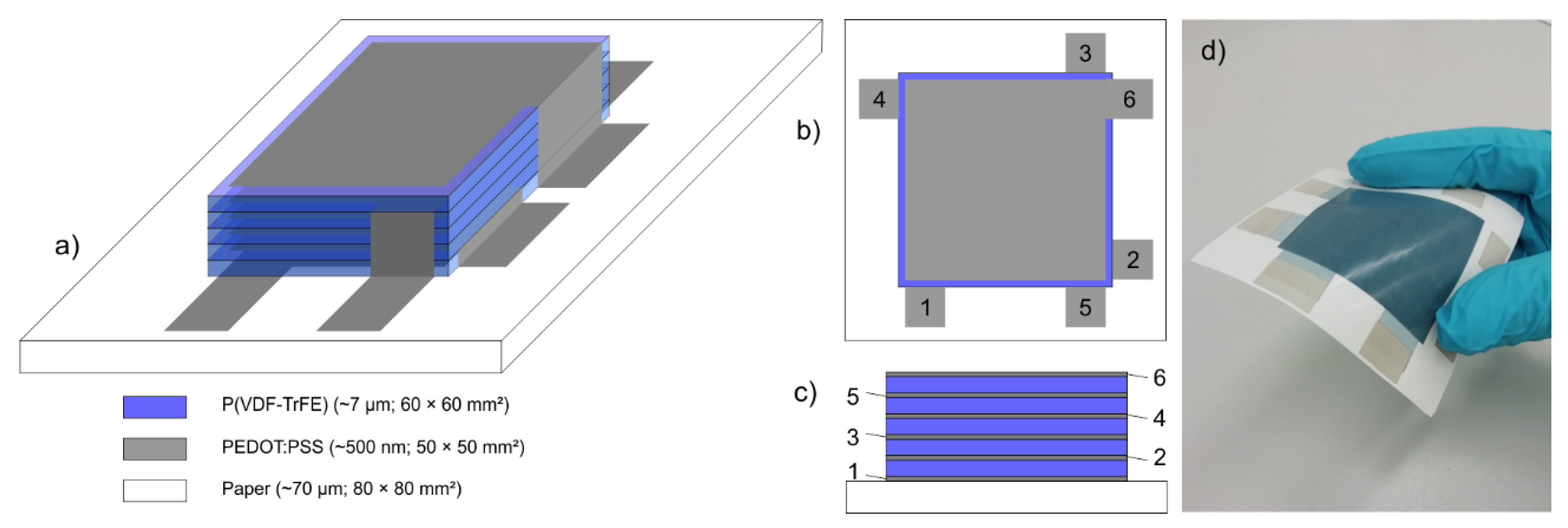
2.1. Device Set-Up and Printing
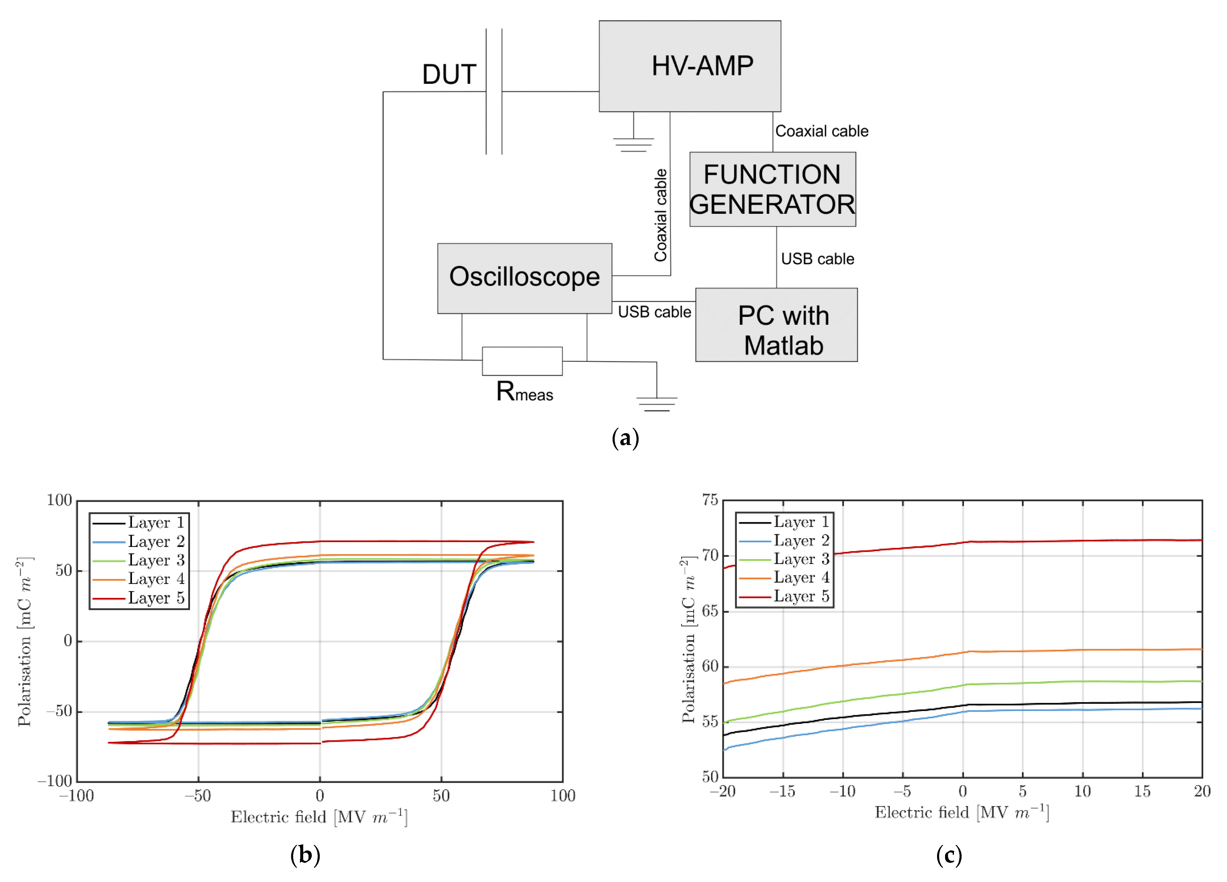
2.2. Poling
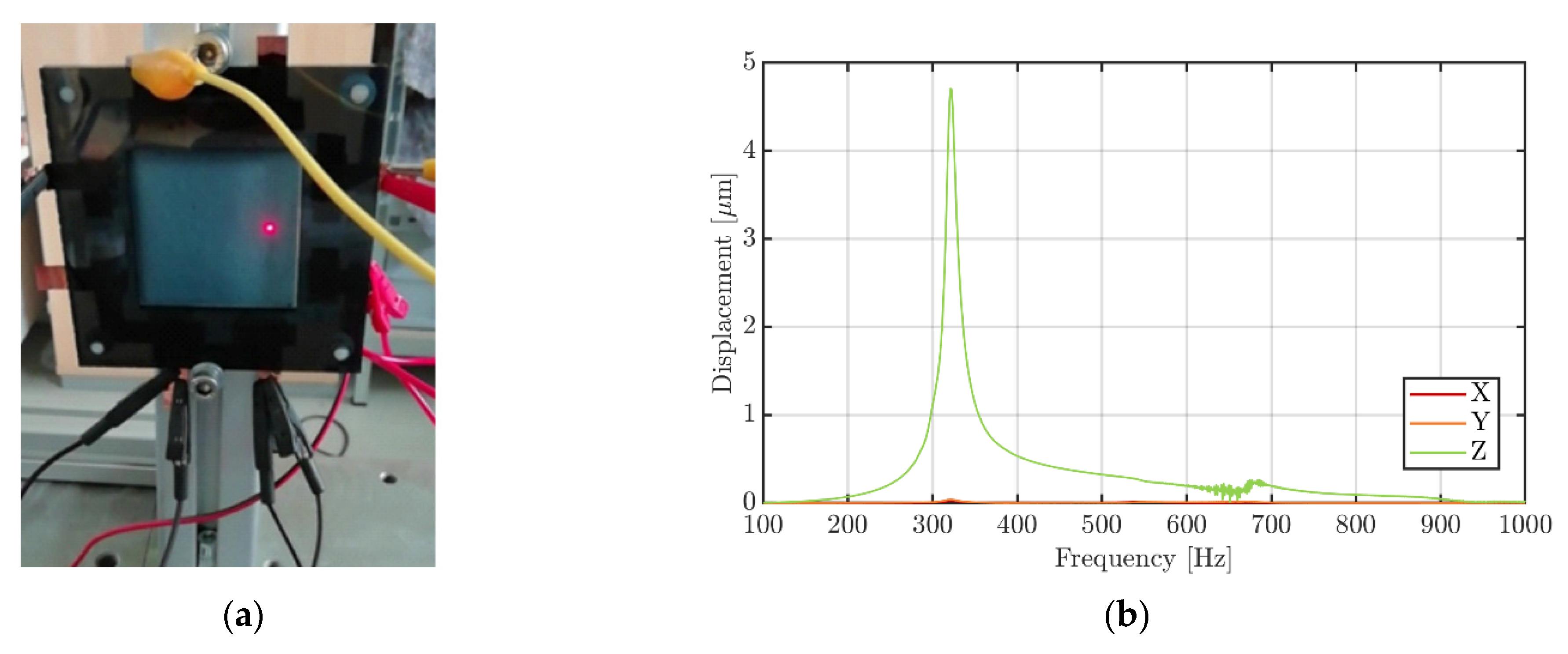
2.3. D-Vibrometry
3. Results and Discussion
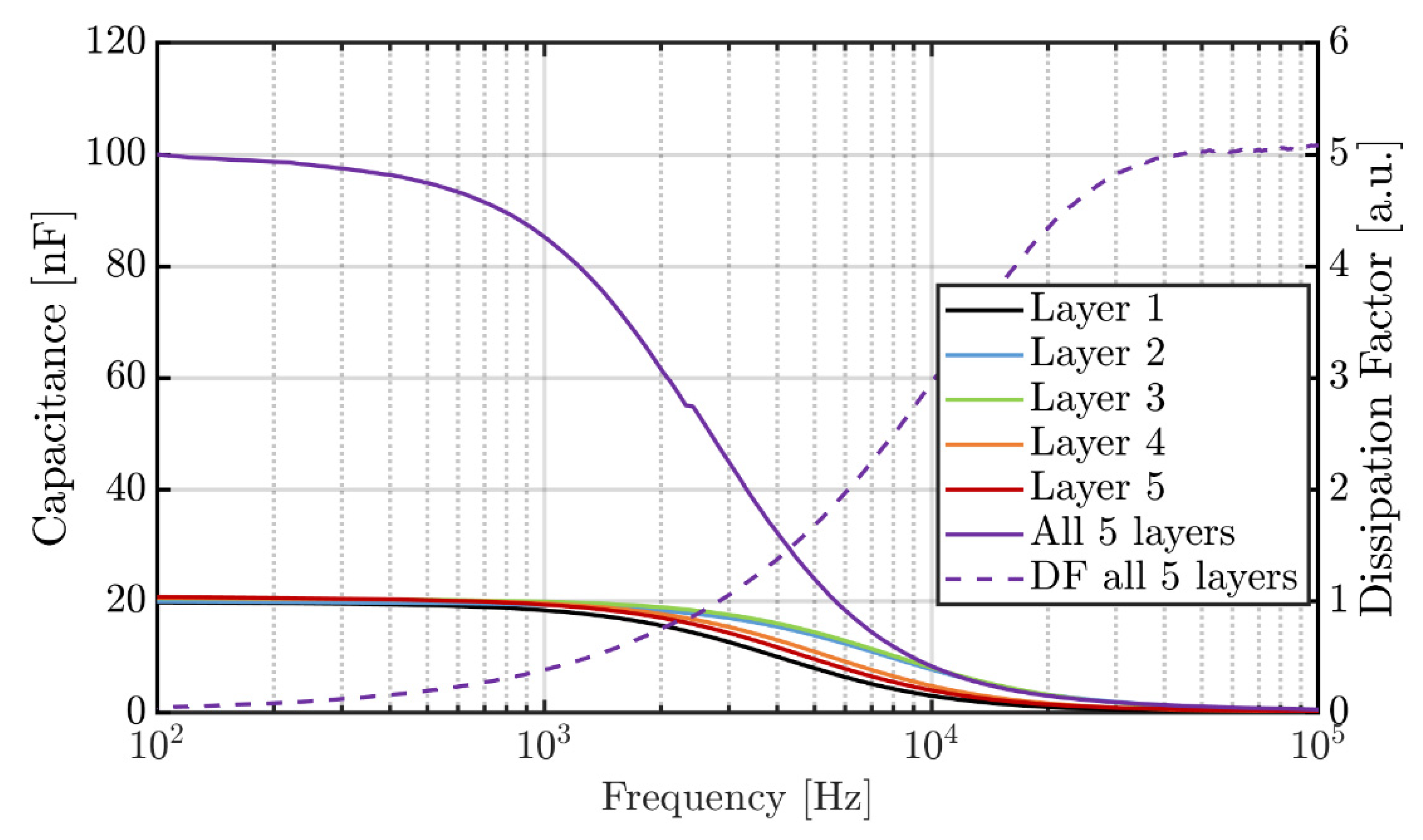
3.1. Poling and Dielectric Spectroscopy
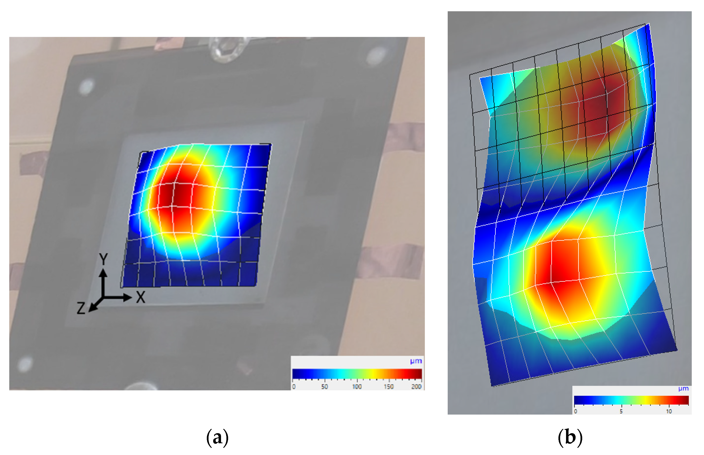
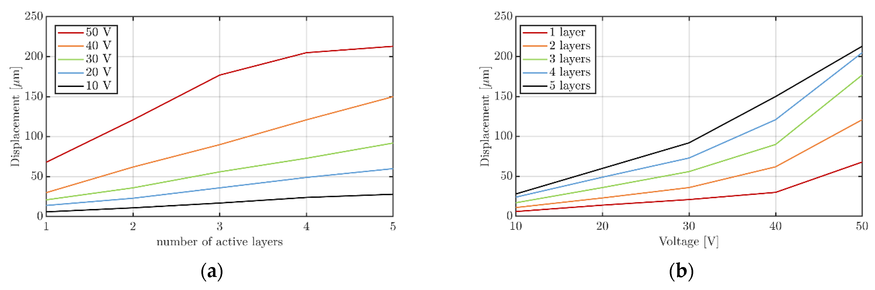
3.2. Resonance Frequency and Deflection under Variable Conditions

| Piezoelectric Material | Substrate | Size | Voltage [Vrms] | Active Layers | Working Frequency [Hz] | Out-of-Plane Displacement [µm] | Ref. |
|---|---|---|---|---|---|---|---|
| P(VDF-TrFE-CTFE) | PET, 188 µm | 65 × 40 mm² | 50 | 1 | 220 | 2 | [17] |
| P(VDF-TrFE-CTFE) | PET, 188 µm | 65 × 40 mm² | 35 | 2 | 220 | 3.5 | [17] |
| P(VDF-TrFE) | PEN, 125 µm | Ø12 mm | 35 | 1 | 3410 | 8 | [32] |
| P(VDF-TrFE) | n.a. | 14 × 19 mm² (incl. frame) | 53 | n.a. | 150 | 95 | [33] |
| P(VDF-TrFE) | paper, 67 µm | 50 × 50 mm² | 50 | 5 | 320 | 213 | this work |
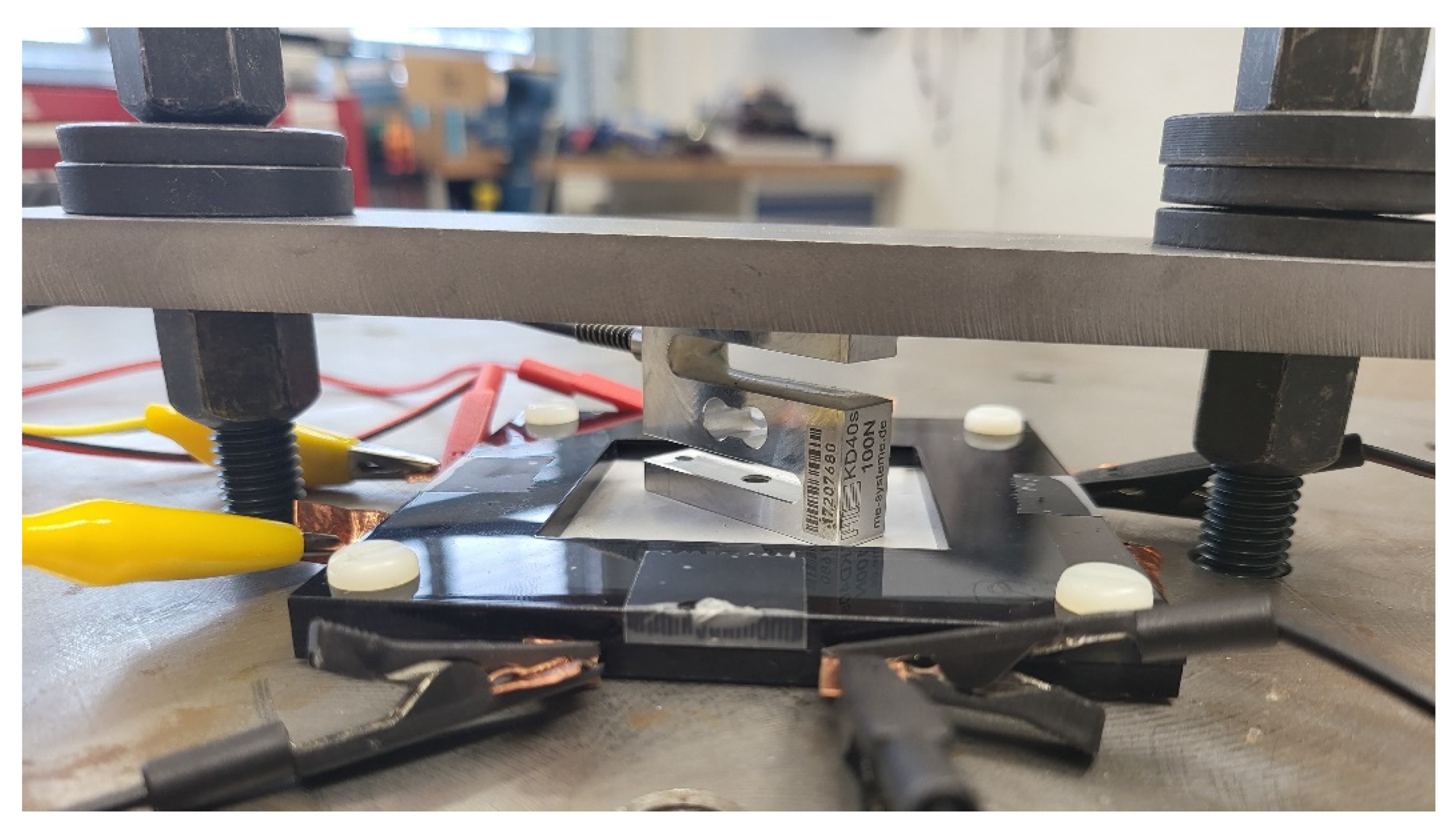
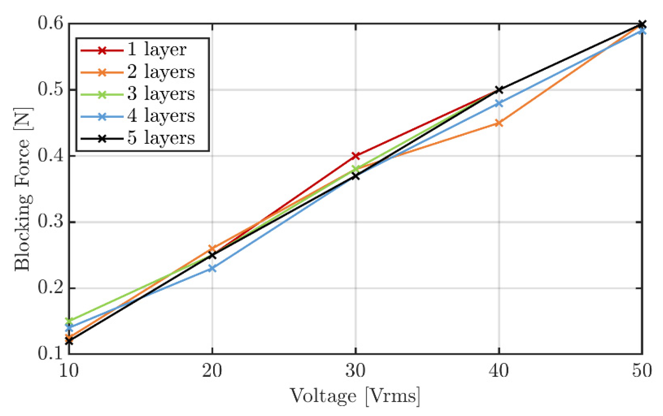
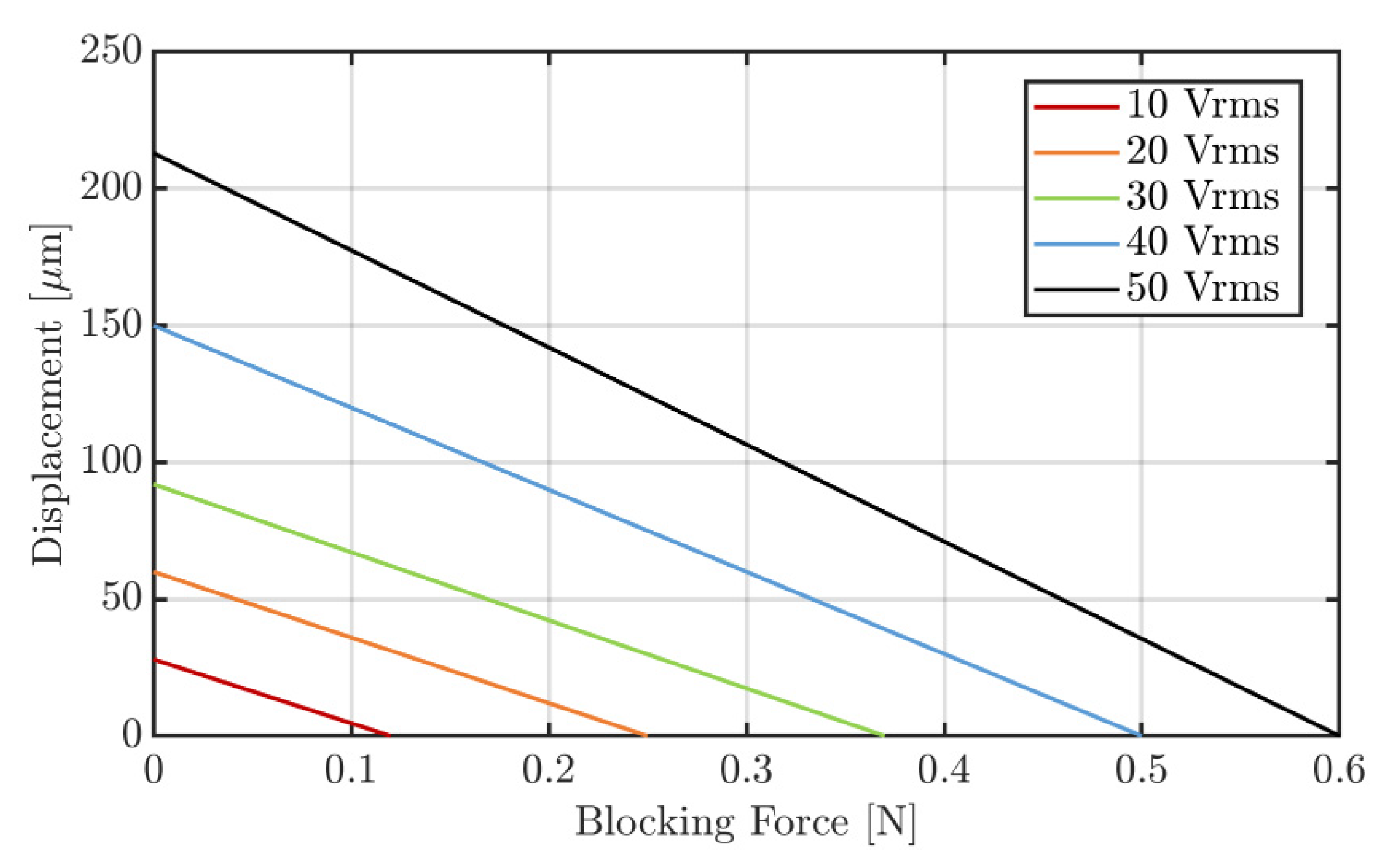
3.3. Blocking Force
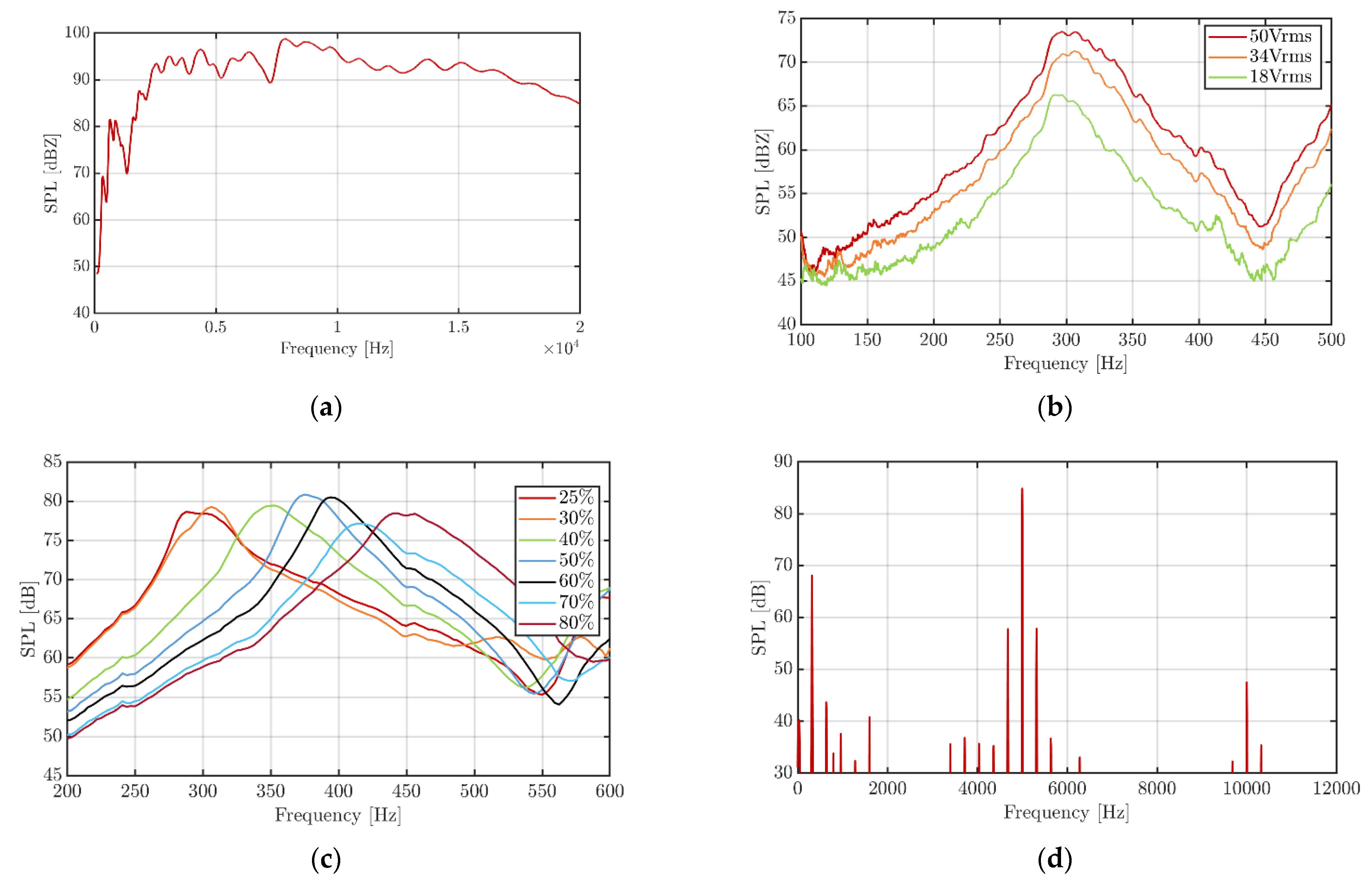
3.4. Acoustical Performance
4. Conclusions
Supplementary Materials
Author Contributions
Funding
Institutional Review Board Statement
Informed Consent Statement
Data Availability Statement
Acknowledgments
Conflicts of Interest
References
- Yin, J.; Hinchet, R.; Shea, H.; Majidi, C. Wearable soft technologies for haptic sensing and feedback. Adv. Funct. Mater. 2021, 31, 2007428. [Google Scholar] [CrossRef]
- Zhu, M.; Sun, Z.; Zhang, Z.; Shi, Q.; He, T.; Liu, H.; Chen, T.; Lee, C. Haptic-feedback smart glove as a creative human-machine interface (HMI) for virtual/augmented reality applications. Sci. Adv. 2020, 6, eaaz8693. [Google Scholar] [CrossRef]
- Sreelakshmi, M.; Subash, T.D. Haptic Technology: A comprehensive review on its applications and future prospects. Mater. Today Proc. 2017, 4 Pt B, 4182. [Google Scholar] [CrossRef]
- Varalakshmi, B.D.; Thriveni, J.; Venugopal, K.R.; Parnaik, L.M. Haptics: State of the art survey. Comput. Sci. Issues 2012, 9, 1694. [Google Scholar]
- Goksel, O.; Sapchuk, K.; Salcudean, S.E. Haptic simulator for prostate brachytherapy with simulated needle and probe interaction. IEEE Trans. Haptics 2011, 4, 188. [Google Scholar] [CrossRef] [PubMed]
- Morris, D.; Joshi, N.; Salisbury, K. Haptic Battle Pong: High-Degree-of-Freedom Haptics in a Multiplayer Gaming Environment. In Proceedings of the Experimental Gameplay Workshop, GDC, San Jose, CA, USA, 22–26 March 2004. [Google Scholar]
- Sun, Z.; Zhu, M.; Chen, Z.; Shan, X.; Lee, C. Haptic-Feedback Ring Enabled Human-Machine Interface (HMI) Aiming at Immersive Virtual Reality Experience. In Proceedings of the 21st International Conference on Solid-State Sensors, Actuators and Microsystems (Transducers), Orlando, FL, USA, 20–24 June 2021; pp. 333–336. [Google Scholar]
- Stramigioli, S.; Secchi, C.; Schaft, A.J.; Fantuzzi, C. Sampled data systems passivity and discrete port-hamiltonian systems. IEEE Trans. Robot. 2005, 21, 574. [Google Scholar] [CrossRef] [Green Version]
- Yao, H.Y.; Grant, D.; Manuel, J.; Hernandez, C. Perceived Vibration Strength in Mobile Devices: The Effect of Weight and Frequency. IEEE Trans. Haptics 2010, 3, 56. [Google Scholar]
- Paneels, S.; Roberts, J.C. Review of Designs for Haptic Data Visualization. IEEE Trans. Haptics 2010, 3, 119. [Google Scholar] [CrossRef] [Green Version]
- Niakosari, S.; Sirouspour, S. Improving Transparency in Network-based Haptics. In Proceedings of the IEEE World Haptics 2009, Salt Lake City, UT, USA, 18–20 March 2009; p. 547. [Google Scholar]
- Gerling, G.J.; Hauser, S.C.; Soltis, B.R.; Bowen, A.K.; Fanta, K.D.; Wang, Y. A bioinspired flexible organic artificial afferent nerve. IEEE Trans. Haptics 2018, 11, 498. [Google Scholar] [CrossRef]
- Huang, Y.; Fan, X.; Chen, S.; Zhao, N. Emerging Technologies of Flexible Pressure Sensors, Materials, Modeling, Devices and Manufacturing. Adv. Funct. Mater. 2019, 29, 1. [Google Scholar] [CrossRef]
- Bar-Cohen, Y. Electroactive Polymer (EAP) Actuators as Artificial Muscles: Reality, Potential, and Challenges; SPIE: Bellingham, WA, USA, 2004. [Google Scholar]
- Carpi, F.; De Rossi, D.; Kornbluh, R.; Pelrine, R.; Sommer-Larsen, P. Dielectric Elastomers as Electromechanical Transducers; Elsevier: Oxford, UK, 2008. [Google Scholar]
- Brochu, P.; Pei, Q. Advances in Dielectric Elastomers for Actuators and Artificial Muscles. Macromol. Rapid Commun. 2009, 31, 10. [Google Scholar] [CrossRef] [PubMed]
- Mistewicz, K.; Nowak, M.; Starczewska, A.; Jesionek, M.; Rzychoń, T.; Wrzalik, R.; Guiseppi-Elie, A. Determination of electrical conductivity type of SbSI nanowires. Mater. Lett. 2016, 182, 78. [Google Scholar] [CrossRef]
- Liu, Y.; Ji, Y.; Yang, Y. Growth, Properties and Applications of Bi0. 5Na0. 5TiO3 Ferroelectric Nanomaterials. Nanomaterials 2021, 11, 1724. [Google Scholar] [CrossRef] [PubMed]
- Gescheider, G.A.; Bolanowski, S.J.; Pope, J.V.; Verrillo, R.T. A four-channel analysis of the tactile sensitivity of the fingertip: Frequency selectivity, spatial summation, and temporal summation. Somatosens. Mot. Res. 2002, 19, 114. [Google Scholar] [CrossRef]
- Ju, W.E.; Moon, Y.-J.; Park, C.-H.; Choi, S.T. A Flexible Tactile-Feedback Touch Screen Using Transparent Ferroelectric Polymer Film Vibrators. Smart Mater. Struct. 2014, 24, 074004. [Google Scholar] [CrossRef]
- Poncet, P.; Casset, F.; Latour, A.; Domingues Dos Santos, F.; Gwoziecki, R.; Fanget, S. Development of haptic button based on electro active polymer actuator. Procedia Eng. 2016, 168, 1500. [Google Scholar] [CrossRef]
- Haque, R.I.; Vié, R.; Germainy, M.; Valbin, L.; Benaben, P.; Boddaert, X. Inkjet Printing of High Molecular Weight PVDF-TrFE for Flexible Electronics. Flex. Print. Electron. 2016, 1, 015001. [Google Scholar] [CrossRef] [Green Version]
- Schmidt, G.C.; Panicker, P.M.; Qiu, X.; Benjamin, A.J.; Quintana Soler, R.A.; Wils, I.; Hübler, A.C. Paper-Embedded Roll-to-Roll Mass Printed Piezoelectric Transducers. Adv. Mater. 2021, 33, 2006437. [Google Scholar] [CrossRef]
- Qiu, X.; Schmidt, G.C.; Panicker, P.M.; Quintana Soler, R.A.; Benjamin, A.J.; Hübler, A.C. Fully Printed Piezoelectric Polymer Loudspeakers with Enhanced Acoustic Performance. Adv. Eng. Mater. 2019, 21, 1900537. [Google Scholar] [CrossRef]
- Lheritier, P.; Noel, S.; Vaxelaire, N.; Domingues Dos Santos, F.; Defay, E. Actuation efficiency of polyvinylidene fluoride-based co-and ter-polymers. Polymer 2018, 156, 270. [Google Scholar] [CrossRef]
- Oh, S.R.; Wong, T.C.; Tan, C.Y.; Yao, K.; Eng-Hock Tay, F. Fabrication of piezoelectric polymer multilayers on flexible sub-strates for energy harvesting. Smart Mater. Struct. 2014, 23, 015013. [Google Scholar] [CrossRef]
- Snis, N.; Edqvist, E.; Simu, U.; Johansson, S. Monolithic fabrication of multilayer P(VDF-TrFE) cantilevers. Sens. Actuators 2008, 144, 314. [Google Scholar] [CrossRef]
- Legrand, J.F. Structure and ferroelectric properties of P(VDF-TrFE) copolymers. Ferroelectrics 1989, 91, 303–317. [Google Scholar] [CrossRef]
- Spampinato, N.; Maiz, J.; Portale, G.; Maglione, M.; Hadziioannou, G.; Paylopoulou, E. Enhancing the ferroelectric performance of P(VDF-co-TrFE) through modulation of crystallinity and polymorphism. Polymer 2018, 149, 66. [Google Scholar] [CrossRef]
- Hübler, A.C.; Bellmann, M.; Schmidt, G.C.; Zimmermann, S.; Gerlach, A.; Haentjes, C. Fully mass printed loudspeakers on paper. Org. Electron. 2012, 13, 2290. [Google Scholar] [CrossRef]
- Quintana Soler, R.A.; Qiu, X.; Benjamin, A.J.; Panicker, P.M.; Schmidt, G.C.; Hübler, A.C. The printed piezoelectric loud-speaker model: A modal perspective from system identification. Appl. Acoust. 2021, 174, 107722. [Google Scholar] [CrossRef]
- Poncet, P.; Casset, F.; Latour, A.; Domingues Dos Santos, F.; Pawlak, S.; Gwoziecki, R.; Devos, A.; Emery, P.; Fanget, S. Static and dynamic studies of electro-active polymer actuators and integration in a demonstrator. Actuators 2017, 6, 18. [Google Scholar] [CrossRef] [Green Version]
- Kemet. Piezoelectric Haptic Modules—Film Flex Assembled Actuators. Available online: https://content.kemet.com/datasheets/KEM_P0106_FFAA.pdf (accessed on 12 July 2021).
- Qiu, X.; Benjamin, A.J.; Venkatesan, T.R.; Schmidt, G.C.; Quintana Soler, R.A.; Panicker, P.M.; Hübler, A.C. Dielectric and electroacoustic assessment of screen-printed piezoelectric polymer layers as flexible transducers: Influence of the electrode material. IEEE Trans. Dielectr. Electr. Insul. 2020, 27, 1683. [Google Scholar] [CrossRef]
- Van Duong, Q.; Nguyen, V.P.; Luu, A.T.; Choi, S.T. Audio-tactile Skinny Buttons for touch User interfaces. Sci. Rep. 2019, 9, 13290. [Google Scholar] [CrossRef]


| Number of Layers | |||||
|---|---|---|---|---|---|
| 1 | 2 | 3 | 4 | 5 | |
| Voltage [Vrms] | Displacement [µm]/Slope [µm V−1 Layer−1] | ||||
| 10 | 6/0.6 | 11/0.55 | 17/0.57 | 24/0.6 | 28/0.56 |
| 20 | 14/0.7 | 23/0.58 | 36/0.6 | 49/0.61 | 60/0.6 |
| 30 | 21/0.7 | 36/0.6 | 56/0.62 | 73/0.61 | 92/0.61 |
| 40 | 30/0.75 | 62/0.78 | 90/0.75 | 121/0.76 | 150/0.75 |
| 50 | 68/1.36 | 121/1.21 | 177/1.18 | 205/1.03 | 213/0.85 |
Publisher’s Note: MDPI stays neutral with regard to jurisdictional claims in published maps and institutional affiliations. |
© 2022 by the authors. Licensee MDPI, Basel, Switzerland. This article is an open access article distributed under the terms and conditions of the Creative Commons Attribution (CC BY) license (https://creativecommons.org/licenses/by/4.0/).
Share and Cite
Schmidt, G.C.; Werner, J.M.; Weissbach, T.; Strutwolf, J.; Eland, R.; Drossel, W.-G.; Hübler, A.C. Printed Multilayer Piezoelectric Transducers on Paper for Haptic Feedback and Dual Touch-Sound Sensation. Sensors 2022, 22, 3796. https://doi.org/10.3390/s22103796
Schmidt GC, Werner JM, Weissbach T, Strutwolf J, Eland R, Drossel W-G, Hübler AC. Printed Multilayer Piezoelectric Transducers on Paper for Haptic Feedback and Dual Touch-Sound Sensation. Sensors. 2022; 22(10):3796. https://doi.org/10.3390/s22103796
Chicago/Turabian StyleSchmidt, Georg C., Jonas M. Werner, Thomas Weissbach, Jörg Strutwolf, Robert Eland, Welf-Guntram Drossel, and Arved C. Hübler. 2022. "Printed Multilayer Piezoelectric Transducers on Paper for Haptic Feedback and Dual Touch-Sound Sensation" Sensors 22, no. 10: 3796. https://doi.org/10.3390/s22103796
APA StyleSchmidt, G. C., Werner, J. M., Weissbach, T., Strutwolf, J., Eland, R., Drossel, W.-G., & Hübler, A. C. (2022). Printed Multilayer Piezoelectric Transducers on Paper for Haptic Feedback and Dual Touch-Sound Sensation. Sensors, 22(10), 3796. https://doi.org/10.3390/s22103796