Conformal Load-Bearing Antenna Structures—Mechanical Loading Considerations

 , ,
, , 
Abstract
:1. Introduction
2. Materials and Methods
- Simple tension;
- Biaxial state of stress;
- Twisting-induced shear loading; and
- Simple tension with disbond on the CLAS arising from manufacturing defect.
3. Results
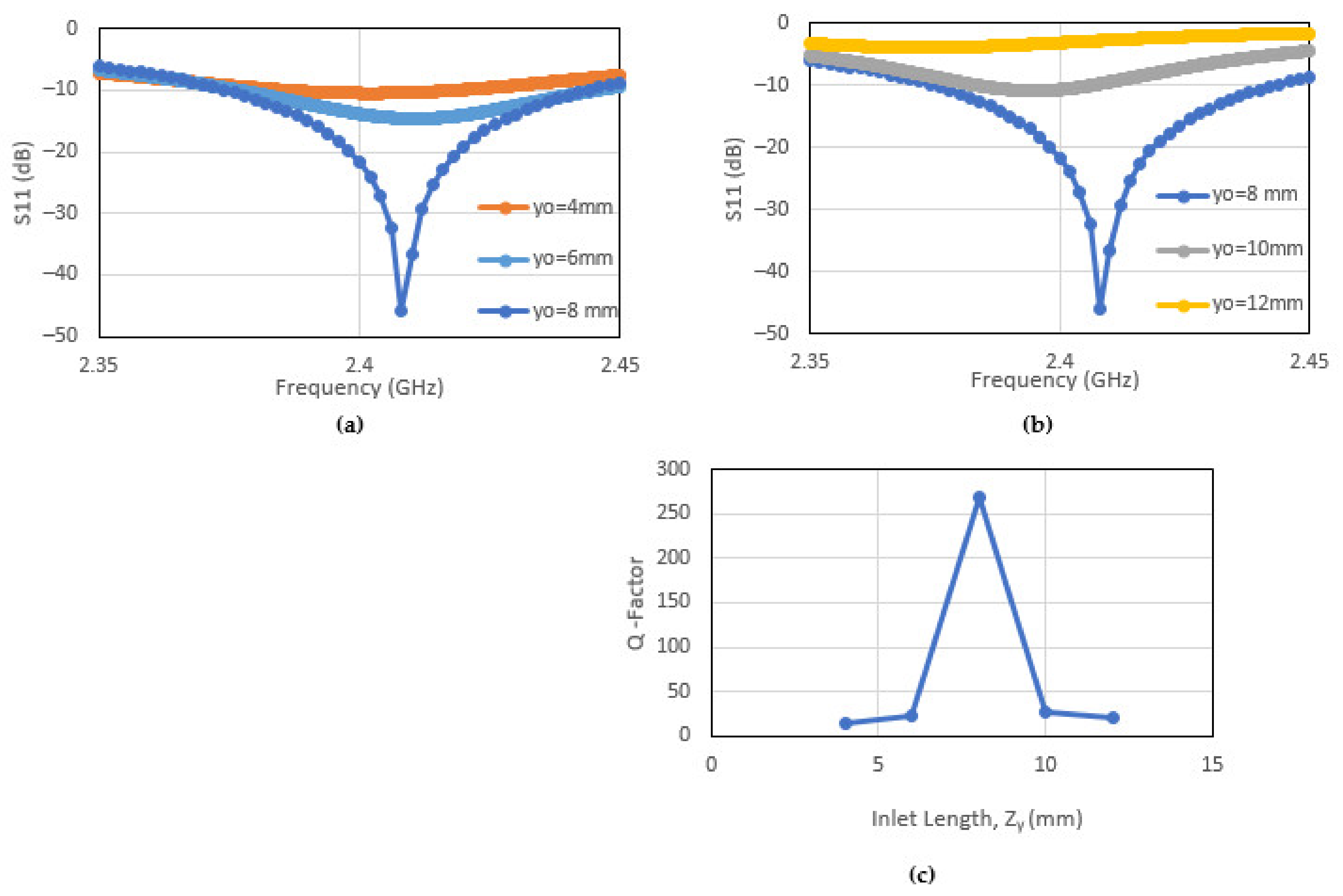
3.1. Patch Antenna Resonance—The Q Factor
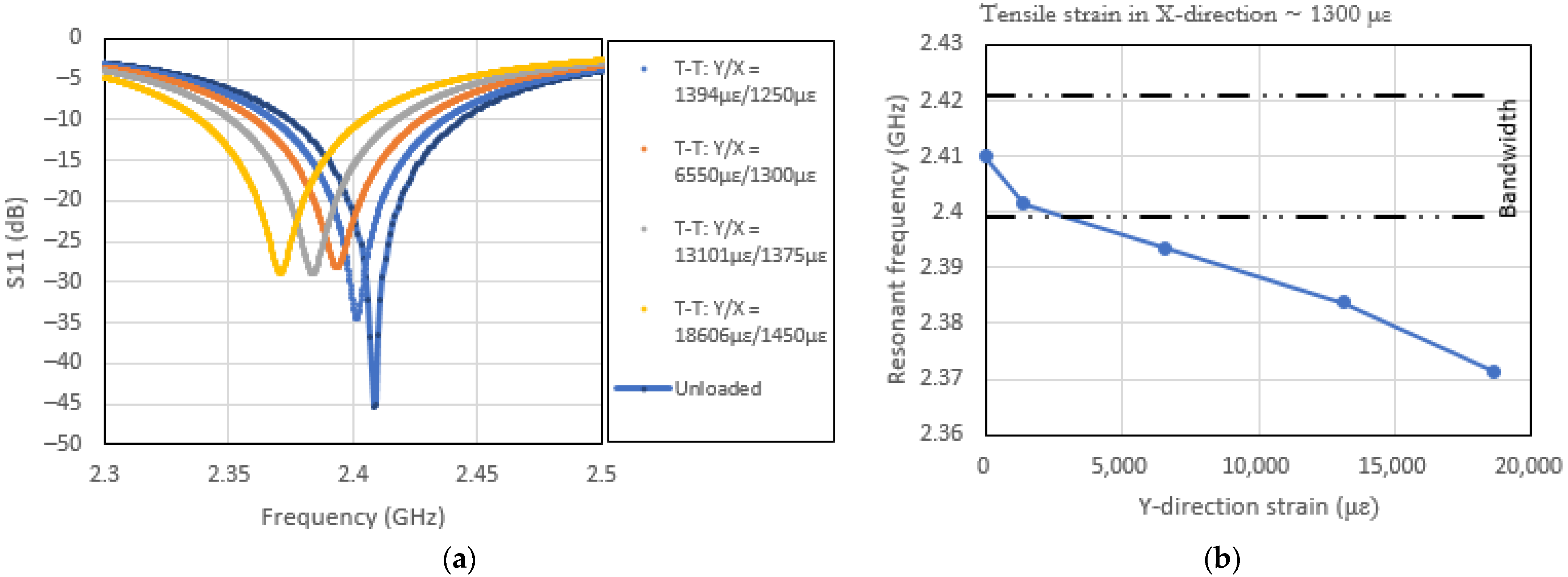
3.2. Effects of Uni-Axial Loading
3.3. Effects of Biaxial Loading
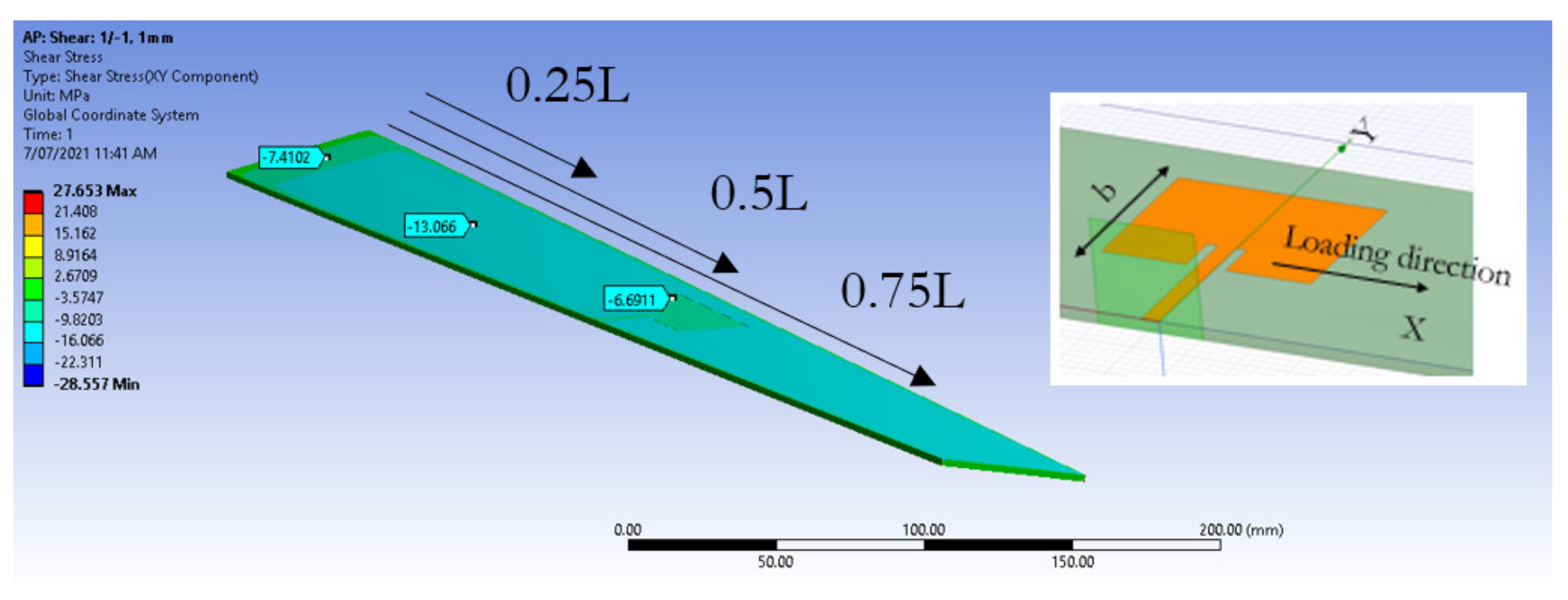
3.4. Effects of Twist
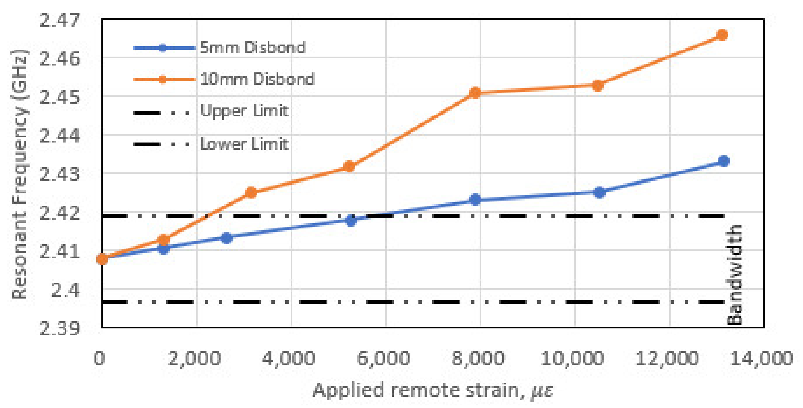
3.5. Effects of Antenna Disbond
4. Discussion
5. Conclusions
Author Contributions
Funding
Institutional Review Board Statement
Informed Consent Statement
Data Availability Statement
Acknowledgments
Conflicts of Interest
References
- Nicholson, K.J.; Rowe, W.S.T.; Callus, P.J.; Ghorbani, K. Split-Ring Resonator Loading for the Slotted Waveguide Antenna Stiffened Structure. IEEE Antennas Wirel. Propag. Lett. 2011, 10, 1524–1527. [Google Scholar] [CrossRef]
- Nicholson, K.J.; Baum, T.C.; Ghorbani, K. Conformal Voronoi Metasurface Antenna Embedded in a Composite Structural Laminate. IEEE Trans. Antennas Propag. 2020, 69, 3717–3725. [Google Scholar] [CrossRef]
- Beziuk, G.; Baum, T.C.; Ghorbani, K.; Nicholson, K.J. Structurally Integrated Radar in an Aerospace Composite Laminate. IEEE Trans. Compon. Packag. Manuf. Technol. 2021, 11, 1835–1843. [Google Scholar] [CrossRef]
- Lockyer, A.; Kudva, J.N.; Kane, D.; Hill, B.P.; Martin, C.A.; Goetz, A.C.; Tuss, J. Qualitative assessment of smart skins and avionic/structures integration. In Proceedings of the 1994 North American Conference on Smart Structures and Materials, Orlando, FL, USA, 13--18 February 1994; pp. 172–183. [Google Scholar]
- Hopkins, M.; Tuss, J.; Lockyer, A.; Alt, K.; Kinslow, R.; Kudva, J. Smart skin conformal load-bearing antenna and other smart structures developments. In Proceedings of the 38th Structures, Structural Dynamics, and Materials Conference, Kissimmee, FL, USA, 7–10 April 1997. [Google Scholar]
- Lockyer, A.; Alt, K.H.; Kudva, J.N.; Tuss, J. Air vehicle integration issues and considerations for CLAS successful implementation. In Proceedings of the SPIE—The International Society for Optical Engineering, Newport Beach, CA, USA, 14 June 2001; p. 4332. [Google Scholar]
- Konter, Y.; Heuts, C.; van Hengel, C. Exploration Of Radiating Aerostructures Ultimate Antenna And Structure Integration. In Proceedings of the I European Conference On Multifunctional Structures (EMuS2019), Barcelona, Spain, 11–12 June 2019. [Google Scholar]
- Callus, P.J. Conformal Load-Bearing Antenna Structure for Australian Defence Force Aircraft, DEFENCE SCIENCE AND TECHNOLOGY ORGANISATION VICTORIA (AUSTRALIA) AIR VEHICLES DIV: Canberra, Australia, March 2007.
- Baek, S.; Ko, M.G.; Kim, M.S.; Joo, Y.S. Structural design of conformal load-bearing array antenna structure (CLAAS). Adv. Compos. Mater. 2017, 26, 29–42. [Google Scholar] [CrossRef]
- Baek, S.; Lim, S.J.; Ko, M.G.; Park, M.Y.; Kim, M.S. Structural Design, Fabrication and Static Testing of Smart Composite Skin Structure: Conformal Load-Bearing SATCOM Array Antenna Structure (CLSAAS). Int. J. Aeronaut. Space Sci. 2019, 21, 50–62. [Google Scholar] [CrossRef]
- Schippers, H.; van Tongeren, H.; Verpoorte, J.; Vos, G. Distortion of conformal antennas on aircraft structures. In Proceedings of the SPIE’s 8th Annual International Symposium on Smart Structures and Materials, Newport Beach, CA, USA, 4–8 March 2001; SPIE: Bellingham, WA, USA, 2001; Volume 4334. [Google Scholar]
- Yoon, K.J.; Kim, Y.S.; Kim, Y.B.; Lee, J.D.; Park, H.C.; Goo, N.S.; Lee, J.H. Parametric study on compression deformation behavior of conformal load-bearing smart skin antenna structure. In Proceedings of the Advances in Fracture and Failure Prevention: Proceedings of the Fifth International Conference on Fracture and Strength of Solids (FEOFS2003): Second International Conference on Physics and Chemistry of Fracture and Failure Prevention (2nd ICPCF), Sendai, Japan, 20–22 October 2003; Trans Tech Publications Ltd.: Bäch, Switzerland, 2004. [Google Scholar]
- Zhong, J.; Kiourti, A.; Sebastian, T.; Bayram, Y.; Volakis, J.L. Conformal Load-Bearing Spiral Antenna on Conductive Textile Threads. IEEE Antennas Wirel. Propag. Lett. 2017, 16, 230–233. [Google Scholar] [CrossRef]
- Joe, J.S.; Park, H.C.; Yoon, K.J.; Goo, N.S. Compressive deformation analysis of smart skin structure embedded with round shape antenna. in Key Engineering Materials. Trans. Tech. Publ. 2006, 321, 963–967. [Google Scholar]
- Yao, L.; Jiang, M.; Zhou, D.; Xu, F.; Zhao, D.; Zhang, W.; Zhou, N.; Jiang, Q.; Qiu, Y. Fabrication and characterization of microstrip array antennas integrated in the three dimensional orthogonal woven composite. Compos. Part B Eng. 2011, 42, 885–890. [Google Scholar] [CrossRef]
- Lu, J.; Gu, Y.; Tang, Y.; Xu, J. Structure and Mechanical Performance Analysis of Functional Structure Integrated Antenna Array. In Proceedings of the 2021 4th International Conference on Electron Device and Mechanical Engineering (ICEDME), Guangzhou, China, 19–21 March 2021; IEEE: New York, NY, USA, 2021. [Google Scholar]
- Dai, F.; Du, S. Analysis of the mechanical and electrical performance of Conformal Load-bearing Antenna Structure. In Proceedings of the ASME 2010 Conference on Smart Materials, Adaptive Structures and Intelligent Systems, SMASIS 2010, Philadelphia, PA, USA, 28 September–1 October 2010; American Society of Mechanical Engineers: Philadelphia, PA, USA, 2010. [Google Scholar]
- Daliri, A.; Wang, C.-H.; John, S.; Galehdar, A.; Rowe, W.; Ghorbani, K.; Callus, P.J. Fea evaluation of the mechanical and electromagnetic performance of slot log-spiral antennas in conformal load-bearing antenna structure (CLAS). In Proceedings of the ASME 2011 Conference on Smart Materials, Adaptive Structures and Intelligent Systems, SMASIS 2011, Scottsdale, Arizona, USA, 18–21 September 2011; American Society of Mechanical Engineers: New York, NY, USA, 2011. [Google Scholar]
- Zhou, Y.; Bayram, Y.; Du, F.; Dai, L.; Volakis, J.L. Polymer-carbon nanotube sheets for conformal load bearing antennas. IEEE Trans. Antennas Propag. 2010, 58, 2169–2175. [Google Scholar] [CrossRef]
- Daliri, A.; Wang, C.-H.; Galehdar, A.; Tian, X.T.; John, S.; Rowe, W.; Ghorbani, K. A slot spiral in carbon-fibre composite laminate as a conformal load-bearing antenna. J. Intell. Mater. Syst. Struct. 2014, 25, 1295–1305. [Google Scholar] [CrossRef]
- Kim, C.K.; Lee, L.M.; Park, H.C.; Hwang, W.; Park, W.S. Impact damage and antenna performance of conformal load-bearing antenna structures. Smart Mater. Struct. 2003, 12, 672–679. [Google Scholar] [CrossRef]
- Yao, L.; Qiu, Y. Design and fabrication of microstrip antennas integrated in three dimensional orthogonal woven composites. Compos. Sci. Technol. 2009, 69, 1004–1008. [Google Scholar] [CrossRef]
- Xu, F.; Sun, L.; Zhang, K.; Wang, L.; Qiu, Y. Electromagnetic performance and impact damage of the microstrip antennas integrated in cylindrical three dimensional woven composite structures. Polym. Compos. 2018, 39, 3259–3267. [Google Scholar] [CrossRef]
- Semkin, V.; Bisognin, A.; Kyrö, M.; Kolmonen, V.-M.; Luxey, C.; Ferrero, F.; Devillers, F.; Räisänen, A. Conformal antenna array for millimeter-wave communications: Performance evaluation. Int. J. Microw. Wirel. Technol. 2017, 9, 241–247. [Google Scholar] [CrossRef] [Green Version]
- Li, P.; Xu, W.Y.; Song, L.W.; Qiu, Y.Y. A novel inversion method of manufacturing flaws in the packaging of conformal load-bearing antenna structure. Int. J. Antennas Propag. 2015, 2015, 795323. [Google Scholar] [CrossRef] [Green Version]
- Mehdipour, A.; Sebak, A.R.; Trueman, C.W.; Rosca, I.D.; Hoa, S.V. Conductive carbon fiber composite materials for antenna and microwave applications. In Proceedings of the 2012 29th National Radio Science Conference (NRSC), Cairo, Egypt, 10–12 April 2012. [Google Scholar]
- Todd, A.; Baum, T.C.; Nicholson, K.J.; Ziolkowski, R.; Ghorbani, K. Towards Carbon Based Artificial Impedance Surfaces for Conformal Aerospace Applications. In Proceedings of the 2018 48th European Microwave Conference (EuMC), Madrid, Spain, 23–27 September 2018. [Google Scholar]
- Rudd, M.; Baum, T.C.; Nicholson, K.J.; Ghorbani, K. Estimating the conductivity of carbon fibre veil (CFV) based on shielding effectiveness. In Proceedings of the 2017 IEEE Asia Pacific Microwave Conference (APMC), Kuala Lumpur, Malaysia, 13–16 November 2017. [Google Scholar]
- Kim, J.; Jeon, W.; Park, K.J.; Choi, J.P. Coexistence of full-duplex-based IEEE 802.15. 4 and IEEE 802.11. IEEE Trans. Ind. Inform. 2018, 14, 5389–5399. [Google Scholar] [CrossRef]
- Balanis, C. Antenna Theory: Analysis and Design; John Wiley & Sons, Inc.: Hoboken, NJ, USA, 2016; ISBN 1118642066. [Google Scholar]
- Nicholson, K.; Dunbabin, O.; Baum, T.; Ghorbani, K. Characterisation of integrated microstrip lines in aerospace composite structure. Electron. Lett. 2017, 53, 36–38. [Google Scholar] [CrossRef]


| 17,600 | 17,600 | 3500 | 0.33 | 0.33 | 0.33 | 6631 | 1250 | 1250 |
| (MPa) | (MPa) | ||
|---|---|---|---|
| 8500 | 0.326 | 814 | 321 |
| Carbon Veil | GMS EP-280 S-Glass | ||
|---|---|---|---|
| Bulk conductivity (S/m) | Dielectric loss tangent | ||
| 5333 | 4.37 | 1.00 | 0.02 |
Publisher’s Note: MDPI stays neutral with regard to jurisdictional claims in published maps and institutional affiliations. |
© 2021 by the authors. Licensee MDPI, Basel, Switzerland. This article is an open access article distributed under the terms and conditions of the Creative Commons Attribution (CC BY) license (https://creativecommons.org/licenses/by/4.0/).
Share and Cite
Healey, R.; Nicholson, K.J.; Wang, J.; Patniotis, J.E.; Lynch, T.; Chiu, W.K. Conformal Load-Bearing Antenna Structures—Mechanical Loading Considerations. Sensors 2022, 22, 48. https://doi.org/10.3390/s22010048
Healey R, Nicholson KJ, Wang J, Patniotis JE, Lynch T, Chiu WK. Conformal Load-Bearing Antenna Structures—Mechanical Loading Considerations. Sensors. 2022; 22(1):48. https://doi.org/10.3390/s22010048
Chicago/Turabian StyleHealey, Rowan, Kelvin J. Nicholson, John Wang, Joel E. Patniotis, Taylor Lynch, and Wing K. Chiu. 2022. "Conformal Load-Bearing Antenna Structures—Mechanical Loading Considerations" Sensors 22, no. 1: 48. https://doi.org/10.3390/s22010048
APA StyleHealey, R., Nicholson, K. J., Wang, J., Patniotis, J. E., Lynch, T., & Chiu, W. K. (2022). Conformal Load-Bearing Antenna Structures—Mechanical Loading Considerations. Sensors, 22(1), 48. https://doi.org/10.3390/s22010048