Abstract
For human head magnetic resonance imaging at 10.5 tesla (T), we built an 8-channel transceiver dipole antenna array and evaluated the influence of coaxial feed cables. The influence of coaxial feed cables was evaluated in simulation and compared against a physically constructed array in terms of transmit magnetic field (B1+) and specific absorption rate (SAR) efficiency. A substantial drop (23.1% in simulation and 20.7% in experiment) in B1+ efficiency was observed with a tight coaxial feed cable setup. For the investigation of the feed location, the center-fed dipole antenna array was compared to two 8-channel end-fed arrays: monopole and sleeve antenna arrays. The simulation results with a phantom indicate that these arrays achieved ~24% higher SAR efficiency compared to the dipole antenna array. For a human head model, we observed 30.8% lower SAR efficiency with the 8-channel monopole antenna array compared to the phantom. Importantly, our simulation with the human model indicates that the sleeve antenna arrays can achieve 23.8% and 21% higher SAR efficiency compared to the dipole and monopole antenna arrays, respectively. Finally, we obtained high-resolution human cadaver images at 10.5 T with the 8-channel sleeve antenna array.
1. Introduction
Fundamentally, the physics of magnetic resonance imaging (MRI) dictates that the achievable signal-to-noise ratio (SNR) increases with magnetic field strength [1,2,3,4]. Hence, ultra-high field (UHF) MRIs at 7 tesla (T) and above can yield higher resolution images or faster acquisition times over conventional high-field MRIs of 1.5 T or 3 T. Currently, a 10.5 T/447 MHz MRI system at University of Minnesota is the highest fully operational whole human body MRI scanner and is at the forefront of the MRI hardware technology [5,6,7,8]. Since the wavelength at 447 MHz (in the presence of human tissue) is within the dimension of the imaging subject, unique challenges, particularly related to overall field homogeneity, arise at UHF, and the design of radiofrequency (RF) coil arrays for MRI applications benefits from serious consideration of antenna concepts [9,10]. This is a significant change from the strict near-field regime-dominated RF coil arrays operating at clinical MRI frequencies below 3 T/128 MHz. At UHF frequencies, radiative-type antennas, particularly dipole antennas, have been suggested as excellent building blocks for transmit arrays and have, indeed, shown promising performance [11,12]. Compared to other coil types, such as loop [13,14] or microstrip antennas [15,16], dipole antennas have the additional advantage of symmetric B1+ field (defined as the transmit magnetic field generated by an RF coil) patterns, as well as a favorable direction of energy propagation (Poynting vector), which results in greater penetration depth. Consequently, both dipole antennas and the combination of loops with dipole antennas have been successfully used for UHF human imaging applications with high penetration, efficiency, and SNR [17,18,19]. However, for realistic head array housings, the coaxial feed cables for dipole antennas have to be routed in close proximity to one leg of the dipole and they interact with the antenna elements.
In a recent publication [8], we had started to evaluate alternative antenna arrays and compared 16-channel dipole and sleeve antenna arrays. Since intra-element coupling due to the tight spacing of the 16 channels can negatively affect the overall antenna array performance, for the study presented here, we compared more sparsely spaced 8-channel arrays. For an 8-channel dipole antenna head array, we first compared an ‘ideal’ coil (Figure 1a) without coaxial cables with a realistic array, which included coaxial cables (Figure 1c), in simulations, and evaluated the effect of coaxial feed cables on the dipole antenna performance. To investigate the influence of this effect experimentally, we built an 8-channel dipole antenna head array and compared two setups: one with a more ideal—but, in practice, unrealistic—coaxial feed cable path (Figure 1e) and the other with a realistic close-proximity coaxial feed cable path (Figure 1g). This allowed us to compare the performance of the 8-channel dipole antenna array with a defined phantom load, both in electromagnetic (EM) simulations and 10.5 T MR experiments with the phantom. To evaluate alternative antenna layouts with possibly more advantageous coaxial feed points for head imaging, we built two end-fed antenna arrays: an 8-channel monopole antenna array [20,21] and an 8-channel sleeve antenna array [8]. Then, we compared the B1+ efficiency (defined as B1+ field normalized by the square root of net input power) and specific absorption rate (SAR) efficiency (defined as B1+/√(peak 10 g SAR)) of the 8-channel dipole, monopole, and sleeve antenna arrays with the phantom. Finally, we compared the performance of these arrays with a human model.
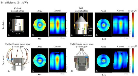
Figure 1.
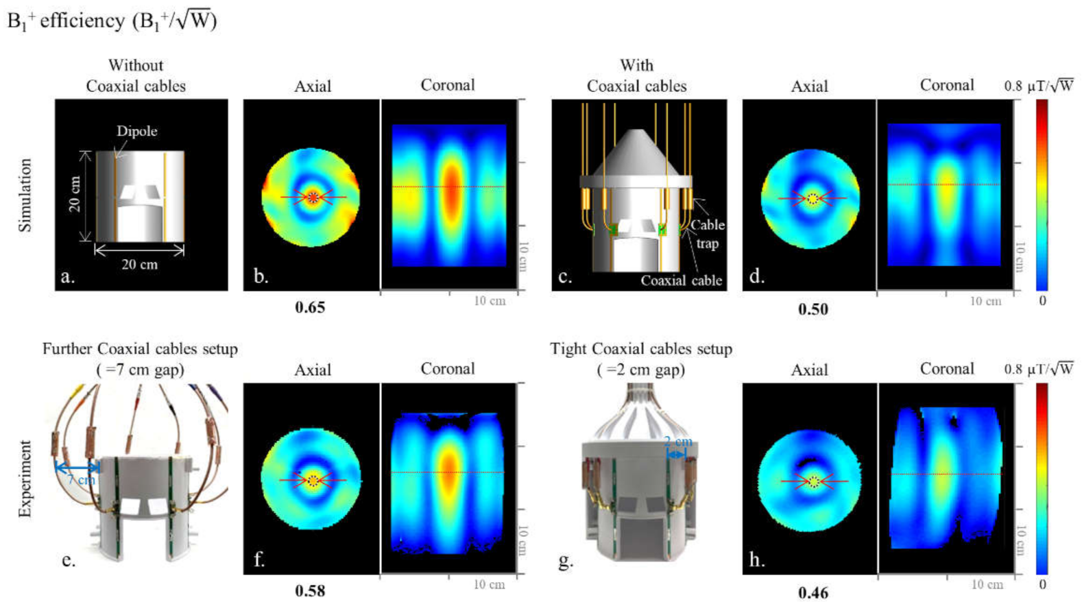
CAD models of the 8-channel inductor-shortened dipole antenna array without (a) and with (c) coaxial cable setups. Corresponding simulated B1+ efficiency maps of the dipole antenna array are shown in (b,d), respectively. Photographs of the 8-channel inductor-shortened dipole antenna array with further (e) and tight (g) coaxial cable setups. Corresponding experimental B1+ efficiency maps of the dipole antenna array are shown in (f,h), respectively.
2. Materials and Methods
2.1. Simulation and Numerical Analysis
Investigating the influence of coaxial cables in detail required that the 8-channel inductor-shortened dipole antenna array was modeled without (Figure 1a) and with (Figure 1c) coaxial cables. EM simulations were performed for both arrays, and the B1+ efficiency (Figure 1b,d,f,h)), 10 g SAR (Figure 2a,b), and SAR efficiency (Figure 2c,d) maps were compared between the two models. Then, for the comparison with 8-channel end-fed antenna arrays, 8-channel monopole (Figure 3a) and sleeve antenna (Figure 3b) arrays were modeled with coaxial cables. B1+ efficiency, 10 g SAR, and SAR efficiency maps of the monopole and sleeve antenna arrays were calculated and compared with the phantom.
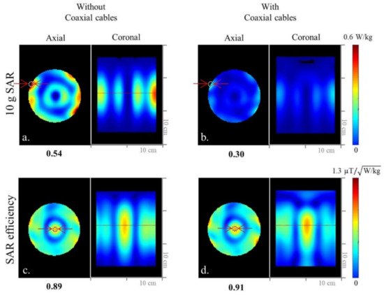
Figure 2.
Simulated 10 g SAR (a,b) and SAR efficiency (c,d) maps of the 8-channel inductor-shortened dipole antenna array without and with coaxial cable setups in the axial and coronal planes.
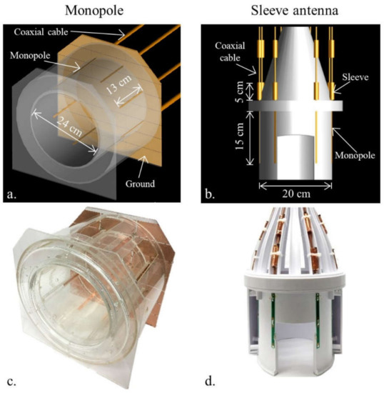
Figure 3.
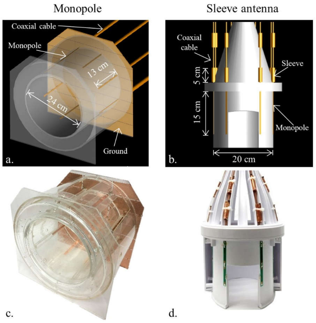
CAD models (a,b) and photographs (c,d) of the 8-channel monopole and sleeve antenna arrays.
A cylindrical phantom with εr = 49 and σ = 0.6 S/m was used to approximate human brain tissue properties for the performance comparison of the arrays. The diameter (=18 cm) and the length (=30.5 cm) of the phantom was chosen to emulate the comparable size of a human head and neck.
The performance of the modeled arrays (dipole, monopole, and sleeve antenna) was compared using a human model (Duke) [22]. To closely resemble the practical coil setup, in which the coaxial feed cables are inherently part of the coil, the antenna models included the coaxial cables and the cable traps. The simulated B1+ efficiency and SAR efficiency were calculated and compared among the three antenna arrays. B1+ efficiency, 10 g SAR, and SAR efficiency of each array were summarized in Table 1.

Table 1.
Quantitative comparison of B1+ efficiency, 10 g SAR, and SAR efficiency among the 8-channel dipole, monopole, and sleeve antenna arrays with human model in the ROI marked for the highest value.
Simulated B- and E-fields were obtained using XFdtd (REMCOM, State College, PA, USA). By driving each of the eight elements, with relative transmit phase increasing by 45 degrees with each channel, the net B1 field generated by the array was in a circularly polarized mode. The portion of the total RF magnetic field that can induce spin excitation, the B1+ fields, were obtained with the equation below:
where Bx and By are the complex amplitudes of the x- and y-oriented RF magnetic fields, respectively [23]. Based on the EM simulation, B1+ efficiency and SAR efficiency maps were calculated with MATLAB (The Mathworks, Inc., Natick, MA, USA). For quantitative comparison, the highest B1+ efficiency, 10 g SAR, and SAR efficiency areas were obtained from the region of interest (ROI) in the axial plane for all arrays. The related values obtained from 2 mm isotropic voxel ROI are indicated below each of the axial images. Red dotted lines of each coronal plane indicate the location of the axial plane and display of B1+ efficiency. Red arrows indicate ROIs where these B1+ efficiency values are measured.
2.2. Construction of 8-Channel Dipole, Monopole, and Sleeve Antenna Arrays
The coil formers for the dipole and sleeve antenna arrays were modeled (Fusion 360, Autodesk, Mill Valley, CA, USA) and then 3D printed (F410, Fusion3 Design, Greensboro, NC, USA). The dipole and sleeve antenna arrays have the same elliptically shaped physical dimensions, with a short and long axis of 20 cm × 22 cm and a length of 20 cm with eight equally spaced antenna elements distanced at 8.8 ± 1.4 cm between individual elements. The individual dipoles and sleeve antennas of the 8-channel dipole and sleeve antenna arrays were tuned to 447 MHz with wound inductors. In Figure 3c, the monopole antenna array was built with a 24 cm × 24 cm dimension and a length of 20 cm on a circular-shaped acrylic former [20,21]. Eight quarter-wave (~13 cm at 10.5 T) monopole antennas were connected to a 35 cm × 36 cm dimension copper ground plate, which was segmented and reconnected with 330 pF capacitors to reduce eddy currents. As shown in our previous research [6,8,17,19], all arrays were operated without an intra-element decoupling circuit.
A lattice balun with two ceramic capacitors (10 pF, 100B series, American Technical Ceramics, Huntington Station, NY, USA) and two inductors (12 nH, A04T_L, Coilcraft Inc., Cary, IL, USA) was used for all matching networks of the 8-channel dipole antenna array. Lattice balun circuits at the feed point and one floating cable trap on the feed cable reduced the sheath current for each element of the 8-channel dipole antenna array. For the comparison in the experiment, the coaxial cables of the dipole antenna array were positioned as a further and tight fit setup. The coaxial feed cable path of the 8-channel dipole antenna array was adjusted to maximize distance from the resonant structure to reduce the interaction between the coaxial cables and elements of the array.
The sleeve antenna array was basically designed with the combination of monopole antennas and floating cable traps [24,25]. To support a better comparison with the inductor-shortened dipole antenna array, the length of the sleeve antenna array elements was also shortened with inductors. For the sleeve antenna array [8], the length of each monopole conductor of the antenna was set to 15 cm with inductor shortening, and combined with a 5 cm floating cable trap for an overall length of 20 cm. For the dipole and sleeve antenna arrays, similar floating cable traps were equipped on the coaxial cables [8,26,27,28].
Supplementary Table S1 summarizes bench measurements obtained from each of the arrays and indicates the range of reflection coefficient (S11) and coupling coefficient (S21) values when the arrays are loaded with a cylindrical phantom. All S11 and S21 were measured in bench measurements using a 16-channel network analyzer (ZNBT8, Rohde & Schwarz, Munich, Germany). The S-parameters of each channel of the 8-channel dipole, monopole, and sleeve antenna arrays were measured in dB-scaled values.
2.3. Experimental Setup
A Siemens MAGNETOM console equipped with 16 independent transmit and 32 receive channels (Siemens, Erlangen, Germany) was used in conjunction with a Siemens SC72 body gradient coil inside the 88 cm diameter whole-body 10.5 T magnet (Agilent, Santa Clara, CA, USA). All data presented here were acquired using parallel transmit (pTx) with equal RF transmit power per channel. An in-house designed 8-channel transmit/receive interface (Virtumed, Minneapolis, MN, USA) with 25 dB receiver gain was used to connect the arrays to the MR scanner. The phantom with exactly the same physical dimensions and electrical properties of the simulation was used to compare the performance of arrays experimentally. The phantom was filled with sucrose, saline, and distilled water solution and measured with the DAKS-12 probe (SPEAG, Zurich, Switzerland) to confirm electrical properties [29]. The phantom was carefully positioned within each of the coil formers to achieve agreement between simulation and experiment and mimic the location for human brain imaging.
For the basic experimental antenna element coupling evaluation of all antenna arrays, noise covariance matrices were obtained in a 10.5 T MR experiment, as illustrated in Supplementary Figure S1. Noise covariance matrices of the dipole antenna with further (Supplementary Figure S1a) and close (Supplementary Figure S1b) coaxial setup, the monopole antenna (Supplementary Figure S1c), and sleeve antenna (Supplementary Figure S1d) arrays were acquired to experimentally evaluate the crosstalk between the elements [30]. Transmit B1+-field efficiency maps of individual elements were obtained using an actual flip-angle imaging (AFI) sequence (TR1/TR2 = 25/115 ms, TE = 3.39 ms, nominal flip angle = 60°, GRAPPA (R = 2), and resolution = 2 mm × 4 mm × 6 mm) with the cylindrical phantom. The flip angle with short TR1 and TR2 was calculated by:
where α = flip angle and n = TR2/TR1, and r ≈ [31]. The flip angle was converted to B1+ with:
where τ is the width in seconds of the RF pulse [32].
α = 2πγ B1+ τ,
To demonstrate overall imaging capabilities and brain coverage, we obtained high-resolution human cadaver images using B1-phase shimming with the 8-channel sleeve antenna array at 10.5 T. High-resolution human cadaver images were obtained for the evaluation of the 8-channel sleeve antenna array utilizing B1-phase shimming (defined as phase optimization using a pTx system). Turbo spin-echo (TSE) images (TR = 5000 ms, TE = 72 ms, TA = 15:18 min, BW = 488 Hz/pixel, NT = 4, FOV = 200 mm × 159 mm, and resolution = 0.39 mm × 0.39 mm × 1.0 mm) and T1-weighted gradient-recalled echo (GRE) images (TR = 150 ms, TE = 3.4 ms, TA = 4:58 min, BW = 421 Hz/pixel, NT = 4, FOV = 200 mm × 200 mm, and resolution = 0.3 mm × 0.3 mm × 1.8 mm) were acquired with the human cadaver.
3. Results
3.1. Evaluation of Interaction among Coaxial Cables and Antenna Elements with the Inductor-Shortened Dipole Antenna Array
As shown in Figure 1 and Figure 2, we evaluated the interaction among coaxial cables and antenna elements with an 8-channel inductor-shortened dipole antenna array in simulation and experiment. A good agreement between simulation (Figure 1b,f) and experiment (Figure 1d,h) of ~10% was achieved for the highest B1+ efficiency values. In simulation, the 8-channel dipole antenna array without coaxial cables (Figure 1b) produced 23.1% higher B1+ efficiency compared to the dipole antenna array with coaxial cables (Figure 1d). The experimental B1+ efficiency of the dipole antenna array with further (=7 cm gap) coaxial setup arrays was shown to be 20.7% higher compared to the tight (=2 cm gap) coaxial cable setup, as shown in Figure 1f,h. Degradation of the B1+ efficiency is the disadvantage from the interference between coaxial cables and antenna elements. However, SAR efficiency values of the dipole antenna array were similar between without (Figure 2c) and with (Figure 2d) coaxial cables, because SAR values (Figure 2a,b) were also decreased as B1+ efficiency values were decreased.
3.2. Comparison of the 8-Channel Monopole and Sleeve Antenna Arrays
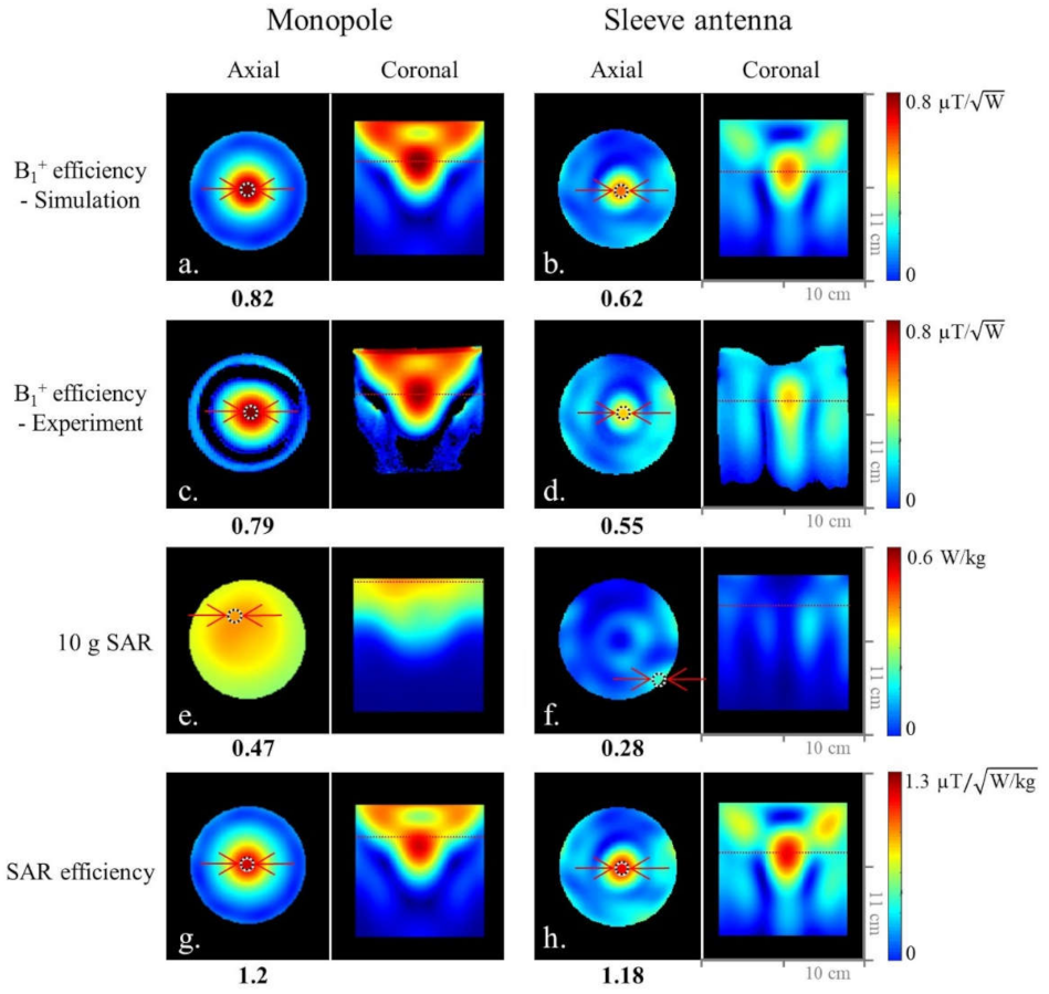
As shown in Figure 4, we compared the 8-channel monopole and sleeve antenna arrays to evaluate the end-fed antenna arrays. Figure 4 shows the simulated (Figure 4a,b)) and experimental (Figure 4c,d) B1+ efficiency comparison between the monopole and sleeve antenna arrays in the central axial and the coronal planes. Within the ROI in Figure 4, the 8-channel monopole antenna array displayed 24.4% and 30.4% higher B1+ efficiency than the 8-channel sleeve antenna array in the simulation and the experiment, respectively.
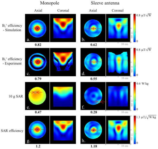
Figure 4.
Simulated (a,b) and experimental (c,d) B1+ efficiency maps of the 8-channel monopole and sleeve antenna arrays in the axial and coronal planes. Simulated 10 g SAR (e,f) and SAR efficiency (g,h) maps of the 8-channel monopole and sleeve antenna arrays in the axial and coronal planes.
The expected peak 10 g SAR values within the phantom of the 8-channel monopole (Figure 4e) and sleeve (Figure 4f) antenna arrays are 0.47 W/kg and 0.28 W/kg, respectively. Compared to the 8-channel monopole antenna array, the results indicate 40.4% higher peak 10 g SAR values of the 8-channel sleeve antenna array. Due to the lower peak 10 g SAR values of the 8-channel sleeve antenna array, both the monopole (Figure 4g) and the sleeve (Figure 4h) antenna arrays showed similar SAR efficiency values.
3.3. Comparison of the Dipole, Monopole, and Sleeve Antenna Arrays with Human Model and Human Cadaver Images with the Sleeve Antenna Array
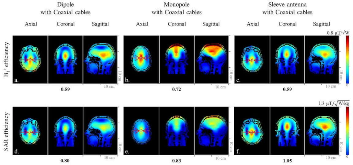
When the simulated human model data were compared within the ROI in Figure 5a–c), the 8-channel sleeve antenna array displayed similar B1+ efficiency to the 8-channel dipole antenna array, and 22% lower B1+ efficiency than the 8-channel monopole antenna array. However, due to the lower peak 10 g SAR values, the 8-channel sleeve antenna array (Figure 5f) showed 23.8% higher and 21% higher SAR efficiency compared to the 8-channel dipole antenna (Figure 5d) and monopole antenna (Figure 5e) arrays, respectively.
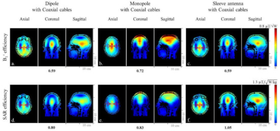
Figure 5.
Simulated B1+ efficiency (a–c) and SAR efficiency (d–f) maps of the 8-channel dipole, monopole, and sleeve antenna arrays with coaxial cables in the axial, coronal, and sagittal planes.
The sleeve antenna array showed relatively small coverage in the phantom (Figure 4b,d). However, with the human model, the sleeve antenna (Figure 5c) did not show smaller B1+ coverage compared to the dipole (Figure 5a) nor the monopole (Figure 5b) antenna arrays.
Figure 6 shows coronal high-resolution TSE and GRE cadaver images obtained at 10.5 T with the 8-channel sleeve antenna array, which demonstrate overall field distribution and coverage. Uniform whole-brain images were achieved with the 8-channel sleeve antenna array utilizing B1 phase shimming technique, while maintaining equal RF amplitude per channel. Optimized pTx excitation techniques can further improve homogeneity and local B1+ efficiency.
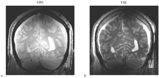
Figure 6.
B1-phase-shimmed GRE (a) and TSE (b) images of the 8-channel sleeve antenna array with human cadaver in the coronal plane.
4. Discussion
We focused on the following three points in this work. First, we evaluated how much degradation was present in an 8-channel dipole antenna array due to the interference among coaxial cables and antennas. Minimizing feed cable interferences is an important point, particularly for UHF head applications, due to the possibility for variance in the distance of the antenna element to the head tissue, which can result in possible stronger interaction of the antenna element with the coaxial feed cable than the imaging object. The second important point is a careful comparison among three different types of 8-channel head antennas. The third point is to demonstrate a close match between the simulation results and the physical experiment. It is important since the accurate simulation of RF coils with human models is ultimately used to estimate the RF coil safety at UHF [6].
The inductor-shortened dipole antenna array—albeit with a practically unrealistic coaxial feed cable routing (Figure 1e,f)—showed higher B1+ efficiency values compared to more practical tight cable routing (Figure 1g,h). This distant feed cable setup utilized for phantom imaging is not practical in most clinical research setups, and a substantial B1+ efficiency drop was observed with a more realistic coaxial feed cable setup. In this respect, the monopole and sleeve antenna arrays have a significant advantage in that the coaxial feed cables are routed away from the patient while keeping the performance of antennas optimal.
In our initial 16-channel research [8], the asymmetric sleeve antenna array concept showed lower peak 10 g SAR and higher SAR efficiency compared to a dipole antenna array. Besides the benefits of the balanced coaxial feed point, this is the result of the principal advantage of the sleeve antenna concept with the important degree of freedom to alter the geometry of the sleeve parts, as well as monopole antenna parts. This allows for a practical compromise between the high E- and B-fields close to the ground plane of classical monopole arrays (Figure 4) and the more advantageous field patterns of dipoles for central slices. The ability of a balanced array feed point positioned away from the tissue/load results in a unique advantage of the sleeve antenna concepts for head applications. As an outcome, in the head array research presented here, we observed reduced peak 10 g SAR for the sleeve antenna array compared to the dipole and monopole antenna arrays. Generally, the feed point of an antenna has high current flow and produces strong E-fields in the imaging sample. In recent 10.5 T dipole antenna work by Sadeghi-Tarakameh [6], this issue was elegantly addressed by increasing the physical distance of the dipole antenna feed point to the sample, resulting in what the author termed a ‘bumped’ dipole antenna. Similarly, the E-fields spread out around the feed points of the sleeve antenna array, since the feed points of the individual antennas were pulled away from the subject for the experimental setup. Consequently, the asymmetric sleeve antenna array has an increased region of 10 g SAR towards the feed point (Figure 4f); however, this spreading out of 10 g SAR distribution leads to lower peak 10 g SAR and higher SAR efficiency values compared to the inductor-shortened dipole antenna array.
The monopole antenna array showed the highest B1+ efficiency with the phantom and the human model compared to the dipole and sleeve antenna arrays close to the ground plane. However, it showed relatively higher peak 10 g SAR with the human model compared to the phantom. Based on comparison among Figure 2, Figure 4 and Figure 5, SAR efficiency of each array was consistently lowered with the human model compared to the phantom. The SAR efficiency of the phantom/human model was 0.91/0.8 (13.8% drop) with the dipole antenna array, 1.2/0.83 (44.6% drop) with the monopole antenna array, and 1.18/1.05 (12.4% drop) with the sleeve antenna array. Due to the nonuniform distance from the antenna to the human subject, SAR efficiency can differ between a human model and a phantom. The field-generating ‘monopole’ antenna parts of both the monopole and the sleeve antennas are expected to perform similarly; however, the classical monopole antenna is using a pronounced ‘RF ground plane’ as an electrical current mirror antenna element. This results in clear differences in E- and B-fields between the monopole and sleeve antenna arrays.
The low peak 10 g SAR leads to the highest SAR efficiency of the sleeve antenna array (Figure 5f) over the ROI compared to the dipole (Figure 5d) and the monopole (Figure 5e) antenna arrays. The highest SAR efficiency in the human model is a particularly important advantage of the asymmetric sleeve antenna array concept compared to both dipole and monopole antenna arrays. The sleeve antenna array has an asymmetric structure that is configured with monopole antennas (i.e., 15 cm) and sleeves (i.e., 5 cm). E-fields of a sleeve antenna change depending on the size of the sleeve. For the sleeve antenna concept, we have the freedom to modify both the geometry of the sleeve parts and the monopole antenna parts.
As shown in Supplementary Table S1 and Figure S1, without any decoupling circuitry, each 8-channel array produced acceptable decoupling values and noise covariance values to proceed with the imaging experiment. However, the coupling and noise covariance of the 8-channel sleeve antenna array (Supplementary Figure S1d) showed the lowest overall values compared to the 8-channel dipole (Supplementary Figure S1a,b) and monopole (Supplementary Figure S1c) antenna arrays. It is an additional advantage of the sleeve antenna concept.
5. Conclusions
We evaluated three types of 8-channel radiative antenna arrays for UHF MRI. Among them, the sleeve antenna array showed clear advantages in terms of lower peak 10 g SAR and higher SAR efficiency compared to the dipole and monopole antenna arrays. Finally, the incorporation of a sleeve into the feed structure has significant positive practical implications, and the variation in sleeve length adds an important degree of design freedom.
The sleeve antenna concepts can also support tighter element spacing, and thus, potentially, could allow for increased density of antenna elements in array configurations. The deliberate lower element counts of arrays presented in this work support better comparison of head-sized dipole and monopole antenna arrays, and they represent an important validation step. For future in vivo human brain imaging research with antenna arrays, the sleeve antenna concept can be further expanded towards a higher number of elements through, for example, dual row layouts and variations in the length of individual antennas. Eventually, we plan to explore combinations of sleeve transmitters with dedicated receiver inserts as an important step towards higher channel array configuration in excess of 32 receive elements. Furthermore, incorporation of high-permittivity materials in support of shorter elements will be considered in addition to further improved geometry arrangements for SAR optimization.
The future experiments will also utilize enhanced B1 field control techniques using pTx with individual control of the phase, amplitude, and RF pulse shape of each coil element and the possibility for significantly improved transmit homogeneity.
Supplementary Materials
The following are available online at https://www.mdpi.com/article/10.3390/s21186000/s1, Figure S1: Noise correlation values of the 8-channel dipole (further (a) and tight (b) coaxial cables setup), monopole (c), and sleeve antenna (d) arrays., Table S1: S-parameters of the 8-channel inductor-shortened dipole, monopole and sleeve antenna arrays. S21 of each array was measured between the nearest, the second nearest, and the third nearest elements.
Author Contributions
M.K.W. built the coils and designed the simulation and experiments. M.K.W. and L.D. collected the data. M.K.W. and S.J. designed the model of the coil former. M.K.W., L.D., R.L.L., Y.W.P., M.T.W., Y.E., S.-H.O., K.U. and G.A. analyzed the results. M.K.W., R.L.L., M.T.W., Y.E., K.U. and G.A. wrote the manuscript. All authors have read and agreed to the published version of the manuscript.
Funding
This research was funded by the U.S. Department of National Institutes of Health under Grants U01-EB025144, S10-RR029672, P41-EB015894, P41-EB027061, P30-NS076408, BK21 FOUR program of the Education and Research Program for Future ICT Pioneers, Seoul National University in A0426-20210100, National Research Foundation of Korea (NRF-2020R1A2C4001623), and the Hankuk University of Foreign Studies Research Fund.
Institutional Review Board Statement
Not applicable.
Informed Consent Statement
Not applicable.
Data Availability Statement
The data presented in this study are available on request from the corresponding author. The data are not publicly available due to the restriction of local law and government policy.
Acknowledgments
The authors would like to thank Andrea Grant, Jeromy Thotland, and Jerahmie Radder (all with the Center for Magnetic Resonance Research, University of Minnesota, Minneapolis, MN, USA) for their help with 3D printing, discussion, and feedback.
Conflicts of Interest
The authors declare no conflict of interest.
References
- Duyn, J.H.; van Gelderen, P.; Li, T.Q.; de Zwart, J.A.; Koretsky, A.P.; Fukunaga, M. High-field MRI of brain cortical substructure based on signal phase. Proc. Natl. Acad. Sci. USA 2007, 104, 11796–11801. [Google Scholar] [CrossRef] [PubMed] [Green Version]
- Guérin, B.; Villena, J.F.; Polimeridis, A.G.; Adalsteinsson, E.; Daniel, L.; White, J.K.; Wald, L.L. The ultimate signal-to-noise ratio in realistic body models. Magn. Reson. Med. 2017, 78, 1969–1980. [Google Scholar] [CrossRef]
- Ugurbil, K. Imaging at ultrahigh magnetic fields: History, challenges, and solutions. Neuroimage 2018, 168, 7–32. [Google Scholar] [CrossRef]
- Uğurbil, K. Magnetic resonance imaging at ultrahigh fields. IEEE Trans. Biomed. Eng. 2014, 61, 1364–1379. [Google Scholar] [CrossRef] [Green Version]
- He, X.; Ertürk, A.; Grant, A.; Wu, X.; Lagore, R.; DelaBarre, L.; Eryaman, Y.; Adriany, G.; Auerbach, E.; Van de Moortele, P.-F.; et al. First in-vivo human imaging at 10.5 T: Imaging the body at 447 MHz. Magn. Reson. Med. 2020, 84, 289–303. [Google Scholar] [CrossRef]
- Sadeghi-Tarakameh, A.; DelaBarre, L.; Lagore, R.; Torrado-Carvajal, A.; Wu, X.; Grant, A.; Adriany, G.; Metzger, G.; Van de Moortele, P.-F.; Ugurbil, K.; et al. In vivo human head MRI at 10.5 T: A radiofrequency safety study and preliminary imaging results. Magn. Reson. Med 2020, 84, 484–496. [Google Scholar] [CrossRef]
- Woo, M.K.; Lagore, R.; DelaBarre, L.; Lee, B.-Y.; Eryaman, Y.; Radder, J.; Erturk, A.; Metzger, G.; Van de Moortele, P.-F.; Ugurbil, K.; et al. A 16-channel transceiver loop+ dipole antennas head array for human head imaging at 10.5 T. In Proceedings of the 9th International Conference on Electromagnetics in Advanced Applications (ICEAA), Verona, Italy, 11–15 September 2017; pp. 1649–1652. [Google Scholar]
- Woo, M.K.; DelaBarre, L.; Waks, M.; Lee, J.; Lagore, R.; Jungst, S.; Grant, A.; Eryaman, Y.; Ugurbil, K.; Adriany, G. Comparison of 16-channel asymmetric sleeve antenna and dipole antenna transceiver arrays at 10.5 Tesla MRI. IEEE Trans. Med. Imaging 2020, 40, 1147–1156. [Google Scholar] [CrossRef] [PubMed]
- Bluem, P.; van de Moortele, P.-F.; Adriany, G.; Popović, Z. Excitation and RF field control of a human-size 10.5-T MRI system. IEEE Trans. Microw. Theory Tech. 2018, 67, 1184–1196. [Google Scholar] [CrossRef] [PubMed]
- Imran, A.I.; Elwi, T.A. A cylindrical wideband slotted patch antenna loaded with frequency selective surface for MRI applications. Eng. Sci. Technol. Int. J. 2017, 20, 990–996. [Google Scholar] [CrossRef]
- Raaijmakers, A.; Ipek, O.; Klomp, D.W.J.; Possanzini, C.; Harvey, P.R.; Lagendijk, J.J.W.; Van den Berg, C.A.T. Design of a radiative surface coil array element at 7 T: The single-side adapted dipole antenna. Magn. Reson. Med. 2011, 66, 1488–1497. [Google Scholar] [CrossRef] [PubMed]
- Wiggins, G.C.; Zhang, B.; Lattanzi, R.; Chen, G.; Sodickson, D. The electric dipole array: An attempt to match the ideal current pattern for central SNR at 7 Tesla. In Proceedings of the 20th Annual Meeting ISMRM, Melbourne, Australia, 5–11 May 2012; p. 541. [Google Scholar]
- Avdievich, N.I.; Hoffmann, J.; Shajan, G.; Pfrommer, A.; Giapitzakis, I.A.; Scheffler, K.; Henning, A. Evaluation of transmit efficiency and SAR for a tight fit transceiver human head phased array at 9.4 T. NMR Biomed. 2017, 30, e3680. [Google Scholar] [CrossRef]
- Shajan, G.; Kozlov, M.; Hoffmann, J.; Turner, R.; Scheffler, K.; Pohmann, R. A 16-channel dual-row transmit array in combination with a 31-element receive array for human brain imaging at 9.4 T. Magn. Reson. Med. 2014, 71, 870–879. [Google Scholar] [CrossRef]
- Adriany, G.; Van de Moortele, P.-F.; Ritter, J.; Moeller, S.; Auerbach, E.J.; Akgun, C.; Snyder, C.J.; Vaughan, T.; Ugurbil, K. A geometrically adjustable 16-channel transmit/receive transmission line array for improved RF efficiency and parallel imaging performance at 7 Tesla. Magn. Reson. Med. 2008, 59, 590–597. [Google Scholar] [CrossRef] [PubMed]
- Adriany, G.; Auerbach, E.J.; Snyder, C.J.; Gözübüyük, A.; Moeller, S.; Ritter, J.; Van de Moortele, P.-F.; Vaughan, T.; Ugurbil, K. A 32-channel lattice transmission line array for parallel transmit and receive MRI at 7 tesla. Magn. Reson. Med. 2010, 63, 1478–1485. [Google Scholar] [CrossRef] [Green Version]
- Ertürk, M.A.; Raaijmakers, A.J.E.; Adriany, G.; Uğurbil, K.; Metzger, G.J. A 16-channel combined loop-dipole transceiver array for 7 tesla body MRI. Magn. Reson. Med. 2017, 77, 884–894. [Google Scholar] [CrossRef] [PubMed] [Green Version]
- Eryaman, Y.; Guerin, B.; Keil, B.; Mareyam, A.; Herraiz, J.L.; Kosior, R.K.; Martin, A.; Torrado-Carvajal, A.; Malpica, N.; Hernandez-Tamames, J.A.; et al. SAR reduction in 7T C-spine imaging using a “dark modes” transmit array strategy. Magn. Reson. Med. 2015, 73, 1533–1539. [Google Scholar] [CrossRef] [PubMed] [Green Version]
- Woo, M.; DelaBarre, L.; Lee, B.-Y.; Waks, M.; Lagore, R.; Radder, J.; Eryaman, Y.; Ugurbil, K.; Adriany, G. Evaluation of a 16-Channel Transceiver Loop+ Dipole Antenna Array for Human Head Imaging at 10.5 Tesla. IEEE Access 2020, 8, 203555–203563. [Google Scholar] [CrossRef]
- Hong, S.M.; Park, J.H.; Woo, M.K.; Kim, Y.B.; Cho, Z.H. New design concept of monopole antenna array for UHF 7T MRI. Magn. Reson. Med. 2014, 71, 1944–1952. [Google Scholar] [CrossRef]
- Woo, M.; Hong, S.-M.; Lee, J.; Kang, C.-K.; Park, S.-Y.; Son, Y.-D.; Kim, Y.-B.; Cho, Z.-H. Extended Monopole antenna Array with individual Shield (EMAS) coil: An improved monopole antenna design for brain imaging at 7 tesla MRI. Magn. Reson. Med. 2016, 75, 2566–2572. [Google Scholar] [CrossRef]
- Christ, A.; Kainz, W.; Hahn, E.G.; Honegger, K.; Zefferer, M.; Neufeld, E.; Rascher, W.; Janka, R.; Bautz, W.; Chen, J.; et al. The Virtual Family—development of surface-based anatomical models of two adults and two children for dosimetric simulations. Phys. Med. Biol. 2009, 55, N23. [Google Scholar] [CrossRef]
- Collins, C.M.; Smith, M.B. Signal-to-noise ratio and absorbed power as functions of main magnetic field strength, and definition of “90°” RF pulse for the head in the birdcage coil. Magn. Reson. Med. 2001, 45, 684–691. [Google Scholar] [CrossRef]
- Kissick, W.; Ingram, W.J.; Vanderau, J.; Jennings, R. Antenna System Guide NIJ Guide 202–00. NCJ 2001, 20531, 18. [Google Scholar]
- Stutzman, W.L.; Thiele, G.A. Antenna Theory and Design; John Wiley & Sons: Hoboken, NJ, USA, 2012. [Google Scholar]
- Mispelter, J.l.; Lupu, M.; Briguet, A. NMR Probeheads for Biophysical and Biomedical Experiments: Theoretical Principles & Practical Guidelines; Imperial College Press: London, UK, 2006; p. 283. [Google Scholar]
- Peterson, D.M.; Beck, B.L.; Duensing, R.C.; Fitzsimmons, J.R. Common mode signal rejection methods for MRI: Reduction of cable shield currents for high static magnetic field systems. Concepts Magn. Reson. B 2003, 19b, 1–8. [Google Scholar] [CrossRef]
- Seeber, D.A.; Jevtic, I.; Menon, A. Floating shield current suppression trap. Concepts Magn. Reson. B 2004, 21b, 26–31. [Google Scholar] [CrossRef]
- Beck, B.; Jenkins, K.A.; Rocca, J.; Fitzsimmons, J. Tissue-equivalent phantoms for high frequencies. Concepts Magn. Reson. B 2004, 20, 30–33. [Google Scholar] [CrossRef]
- Jesmanowicz, A.J.; Hyde, S.; Froncisz, W.; Kneeland, B.J. Noise correlation. Magn. Reson. Med. 1991, 20, 36–47. [Google Scholar] [CrossRef] [PubMed]
- Yarnykh, V.L. Actual flip-angle imaging in the pulsed steady state: A method for rapid three-dimensional mapping of the transmitted radiofrequency field. Magn. Reson. Med. 2007, 57, 192–200. [Google Scholar] [CrossRef] [PubMed]
- Hartwig, V.; Vanello, N.; Giovannetti, G.; De Marchi, D.; Lombardi, M.; Landini, L.; Santarelli, M.F. B1+/actual flip angle and reception sensitivity mapping methods: Simulation and comparison. Magn. Reson. Med. 2011, 29, 717–722. [Google Scholar] [CrossRef] [PubMed]


Publisher’s Note: MDPI stays neutral with regard to jurisdictional claims in published maps and institutional affiliations. |
© 2021 by the authors. Licensee MDPI, Basel, Switzerland. This article is an open access article distributed under the terms and conditions of the Creative Commons Attribution (CC BY) license (https://creativecommons.org/licenses/by/4.0/).