Letter

A Dynamic Hysteresis Model and Nonlinear Control System for a Structure-Integrated Piezoelectric Sensor-Actuator

State Key Laboratory of Robotics and System, Harbin Institute of Technology, Harbin 150001, China
*
Author to whom correspondence should be addressed.
Sensors 2021, 21(1), 269; https://doi.org/10.3390/s21010269
Submission received: 7 December 2020 / Revised: 23 December 2020 / Accepted: 30 December 2020 / Published: 3 January 2021
(This article belongs to the Special Issue Advanced Flexible Sensors and Electronics)

Abstract

:
The piezoelectric sensor-actuator plays an important role in micro high-precision dynamic systems such as medical robots and micro grippers. These mechanisms need high-precision position control, while the size of the sensor and actuator should be as small as possible. For this paper, we designed and manufactured a structure-integrated piezoelectric sensor-actuator and proposed its PID (Proportion Integral Differential) control system based on the dynamic hysteresis nonlinear model and the inverse model. Through simplifying the structure of the piezoelectric sensor-actuator by the centralized parameter method, this paper establishes its dynamic model and explores the input–output transfer function by taking the relationship between the output force and displacement as the medium. The experiment shows the maximum distance of the hysteresis curve is 0.26 μm. By parsing the hysteresis curve, this paper presents a dynamic hysteresis nonlinear model and its inverse model based on a 0.5 Hz quasi-static model and linear transfer function. Simulation results show that the accuracy of the static model is higher than that of the dynamic model when the frequency is 0.5 Hz, but the compensation accuracy of the dynamic model is obviously better than that of the static model with the increase of the frequency. This paper also proposes a control system for the sensor-actuator by means of the inverse model. The simulation results indicate that the output root mean square error was reduced to one-quarter of the original, which proves that the structure-integrated piezoelectric sensor-actuator and its control system have a great significance for signal sensing and output control of micro high-precision dynamic systems.

1. Introduction

The research about piezoelectric sensor-actuators involves the development of composite materials with integrated sensing functions [1], structural health detection and correction [2], flexible actuators with variable stiffness [3,4], nano-level manipulators [5,6], medical robots and micro grippers [7,8]. Piezoelectric sensor-actuators can be divided into two types: structure-integrated and function-integrated. In structure-integrated mode, two devices are utilized to realize the sensing function and actuating function, respectively. However, the function-integrated type takes the sensing function and actuating function as one device, which always leads to the coupling of driving signal and sensing signal. Therefore, the research on function-integrated piezoelectric sensor-actuators is mainly concentrated on how to separate the driving electric signal and sensing electric signal [9]. This paper focusses on the structure-integrated piezoelectric sensor-actuator.
Boukabache et al. [10] studied the application of piezoelectric sensor-actuators in nondestructive testing of aerospace equipment. Zhang et al. [11] utilized the piezoelectric effect to expound a piezoelectric bimorph pump using discrete categories of piezoelectric ceramic as pistons to control the liquid flow while sensing the difference between internal and external pressure. Lee et al. [12] researched the use of adaptive wave cancellation in a new multilayer smart skin sensor which contains piezoelectric materials as actuators and sensors to attenuate the primary low-frequency noise underwater. Varanis et al. [13] discussed the piezoelectric sensor-actuator as an MEMS accelerometer for mechanical vibration analysis while Rathod [14] summarized the applications of piezoelectric sensor and actuators for MENS.
At the same time, some inherent problems of piezoelectric materials have come to people’s attention. Inherent defects such as the creep and hysteresis nonlinear characteristics of piezoelectric ceramics mean the accuracy of high-precision displacement output system cannot be guaranteed, especially in a dynamic system. In some conditions the maximum relative output displacement error is 25% without control [15]. Therefore, many researchers commenced to design operational units to characterize the nonlinearity and establish various hysteresis models in order to analyze and solve the hysteresis problem [16]. For example, Hu [17] demonstrated that the classical Preisach model is efficient enough only when the load fluctuation is relatively small. Mayergoyz [18] proposed a generalized Preisach model while introducing an integral function. Chen et al. [19], Luo et al. [20] and other researchers tried to improve the accuracy of the Preisach model [21]. Meanwhile, Tan et al. [22] essentially derived a singularity free Prandtl–Ishlinskii model from the Preisach model to extend the P-I operator to map the hysteresis data, and developed a feedforward controller. Based on this, there are still many researchers looking to further develop this kind of model, such as Al Janaideh et al. [23,24], Gu et al. [25,26,27] and Hao et al. [28] In addition, Banks et al. [29] derived the Krasonsel’skii–Pokrovskii (K-P) model from the Preisach model. Goldfarb [30] presented a generalized Maxwell resistive capacitor as a lumped parameter causal representation of rate-independent hysteresis. Chen et al. [31] proposed a dynamic model to describe the voltage-force hysteresis curve based on the piezoelectric actuator, as Li et al. [32] did. As for the control system, Ang et al. [33] developed a feedforward controller with an inverse rate-dependent model. Gan et al. [16] thought that feedforward-feedback control and feedback control were the emphasis in the future. Yi et al. [34] reported an adaptive feedforward controller to solve the hysteresis problem. Some other researchers such as Tan et al. [22], Davoodi et al. [35] and Saleem et al. [36] focused on developing feedforward controls. Combining the PID controller with the inverse hysteresis model, the feedforward-feedback control [25] is part of the most popular and effective controls.
However, existing related research on piezoelectric sensor-actuators mainly focuses on how to improve the accuracy of the model to describe the dynamic characteristics of piezoelectric materials. Mostly it focuses on the material properties and the lack of research on the background of structure-integrated piezoelectric sensor-actuators, which means that the research on structural integrated piezoelectric sensor-actuators and their control systems is very scarce. In the existing related research on structural integrated piezoelectric sensor-actuators, the difficulties with the inverse hysteresis model [37] and the poor output accuracy of the actuator [38] are still to be solved. Therefore, based on research on the structure-integrated piezoelectric sensor-actuator, this paper presents a dynamic hysteresis model based on building a nonlinear control system to achieve the displacement correction of the microsystem after sensing, which provided a fine application foreground for a structure-integrated piezoelectric sensor-actuator in a micro high-precision integrated system.

2. Design of Piezoelectric Sensor-Actuator

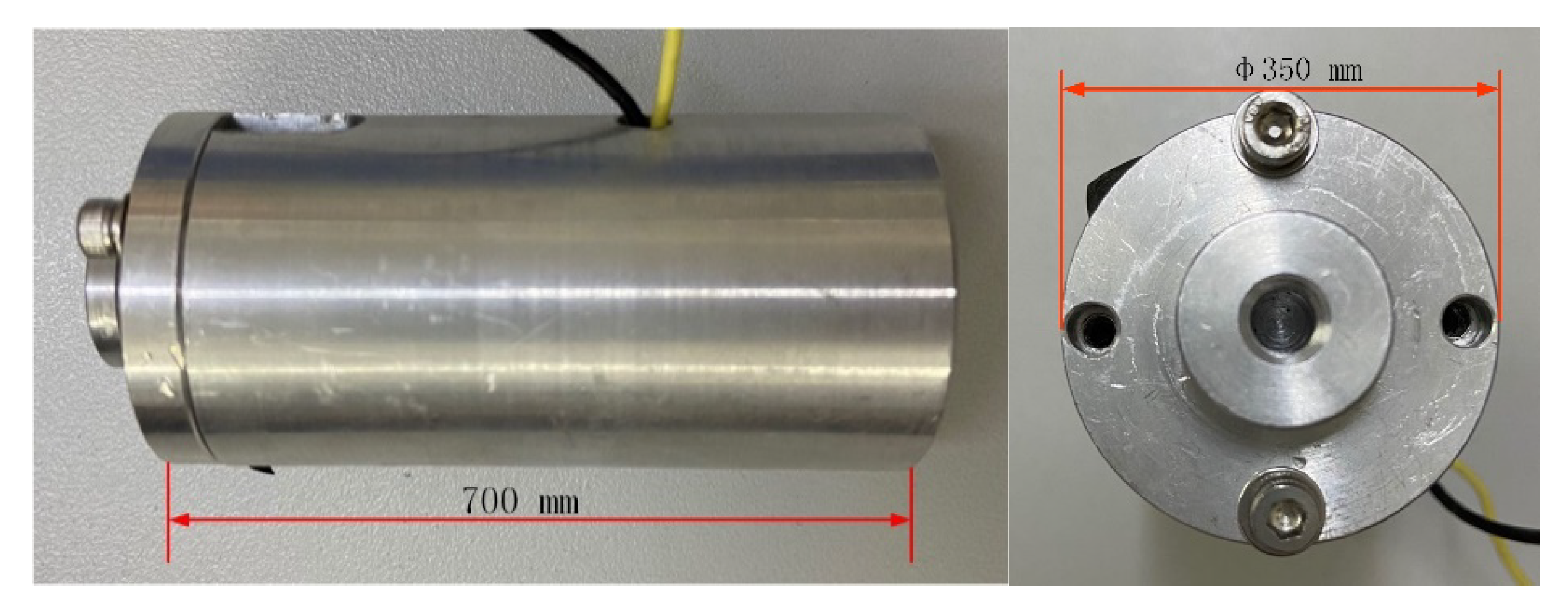
2.1. Structure Design of Piezoelectric Sensor-Actuator

In order to meet the frequency response characteristics, the annular quartz wafer (5 × 12 × 1 mm) was selected and packaged with stainless steel as the sensor part of the system. Considering the load and preload for the structure-integrated sensor-actuator, we employed an electron beam to seal. As for the actuator, the structure of the PZT was 11 × 11 × 37 mm (284 pieces × 0.13 mm). Figure 1 illustrates the structure of the piezoelectric sensor-actuator. The prototype of the piezoelectric sensor-actuator is shown in Figure 2. The parameters of the PZT are listed in Table 1.

2.2. The Mathematical Model of the Piezoelectric Sensor-Actuator

The piezoelectric sensor in this paper was an x-direction cut quartz wafer, which can produce a tensile piezoelectric effect. The piezoelectric actuator works under the first boundary condition which is that the mechanical end is free and the electrical signal is short-circuited (Specific description is that the piezoelectric stack working under the condition in which stress on the boundary of the piezoelectric stack is zero, but the strain is not zero and the internal electric field is zero or constant, but the potential displacement was not zero or constant). In this way, we calculated the output displacement of the piezoelectric stack as
x = S 3 n h = ( s 33 E T 3 + d 33 E 3 ) h n = n ( h s 33 E l b F o u t + d 33 u a )
where x means the displacement of the actuator, S3 means the strain of the piezoelectric stack, T3 means the stress, d33 means the piezoelectric constant, E3 means the external electric field, S 33 E means the short circuit elastic compliance coefficient with constant electric field, h means the thickness of a single piezoelectric ceramic sheet, n is the number of layers of piezoelectric laminated ceramics, l means the length of the piezoelectric ceramic sheet, b means the width of the piezoelectric ceramic sheet, Fout means the direction output force of piezoelectric stack, ua means the drive voltage of the piezoelectric stack.
This paper describes the piezoelectric driving amplifier as a series circuit of gain kamp and resistance R. Piezoelectric ceramic actuators are described as capacitors Ca. The equivalent physical model of piezoelectric driving amplifier is
R C a d u a ( t ) d t + u a ( t ) = k a m p u c ( t )
where uc means the output voltage of driving amplifier.
The equivalent voltage produced by quartz sensor is
u s = q C s = q h ε 0 ε r A = d 11 h F o u t ε 0 ε r A
where q means the charge produced by quartz, A means the area of the piezoelectric quartz, h means the thickness of the quartz, εr means the relative permittivity of quartz, ε0 means the dielectric constant of air.
Using the centralized parameter method to simplify the system as shown in Figure 3, the system can be equivalent to a spring damping system and the piezoelectric actuator pushes the push rod to carry out one-dimensional reciprocating motion, so that the dynamical model of the system is
m x ¨ + c f x ˙ + ( k f + k a ) x = F o u t
where m is the equivalent mass of moving parts of the piezoelectric sensor-actuator system, cf is the equivalent viscosity coefficient of actuator structure, kf is the stiffness coefficient of actuator, ka means the equivalent stiffness of preload, Fout is the input force of piezoelectric ceramic stack on push rod spring, x is the displacement of push rod end.
Simultaneously, (1)~(4), the differential equation of the system is
R C a d u a ( t ) d t + u a ( t ) = k a m p u c ( t ) m x ¨ + c f x ˙ + ( k f + k a ) x = k a n d 33 u a = k a k d u a
Laplace transforming the above equation, the transfer function from the control voltage generated by the sensor to the displacement output is
G s y s ( s ) = K ω 2 s 2 + 2 ξ ω n s + ω n 2 k d k a m p R C a s + 1

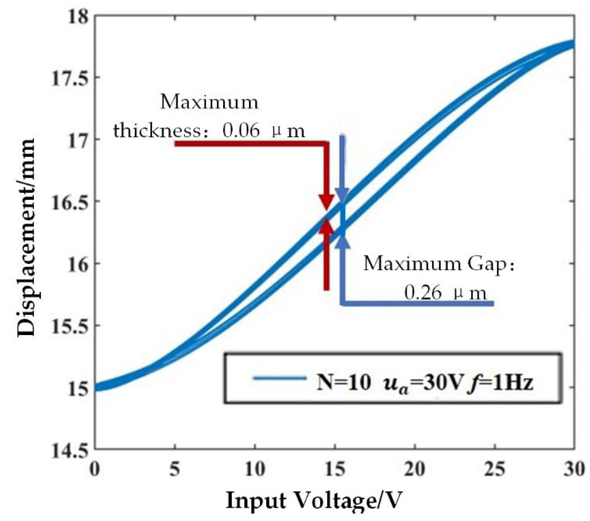
2.3. Experimental Study on Hysteresis of Piezoelectric Sensor-Actuator

Because of the hysteresis of piezoelectric material, the prototype is checked to explore the relationship between the input and output of piezoelectric sensor-actuator. In this paper, the hysteresis characteristics of the actuator made of piezoelectric ceramic stack are mainly considered. Therefore, the driving voltage generated by the sensor is equal to a sinusoidal excitation signal with 0 ~ 30 V and 0.5 Hz.
The experiment is shown in Figure 4. Figure 5 illustrates the curve of the end displacement of the push rod with the input voltage signal.
As shown as Figure 5, when the voltage is 15 V, the hysteresis phenomenon is the most obvious, and the distance between the two voltage curves is 0.26 μm. For the same voltage value, the thickest part of the curve is 0.06 μm which means the maximum displacement repetition deviation is 0.06 μm.

3. Dynamic Hysteresis Model of Piezoelectric Sensor-Actuator

3.1. Dynamic Hysteresis Nonlinear Model of Piezoelectric Sensor-Actuator

The classical Prandtl–Ishlinskii (P-I) model is a static model which is greatly affected by the value of the play operator and the density function, and it is a linear model. However, as shown in Equation (5), the hysteresis characteristics of piezoelectric actuators with ceramic stacks are closely related to the driving voltage frequency. In order to improve the accuracy of the model, this paper proposed a dynamic model based on the static model. The excitation signal collected by the piezoelectric sensor is input to the 0.5 Hz quasi-static model through the calculation and processing of the transfer function, and then the output signal of the piezoelectric actuator is obtained, as shown in Figure 6.
The modeling accuracy of the classical P-I model is mainly determined by the experimental data acquisition accuracy, the number of operators and the initial value of the density function. In order to obtain a 0.5 Hz quasi-static model, simplify the identification process and shorten the modeling period, the function relationship between the threshold value of independent variable r and the density function q is simplified to the corresponding relationship with the weight ω.
Therefore, the mathematical expression of the model can be simplified as
Π [ v ] ( t ) = q v ( t ) + i = 1 n w i F r i [ v ] ( t )
Nine threshold values are taken as r= [0,0.1,0.2,0.3,0.4,0.5,0.6,0.7,0.8]. The identification results are
ω = [ 0.58751 , 0.46211 , 0.06758 , 0.00092 , 0.30240 , 0.99999 , 0.20197 , 0.73566 , 0.15913 ] . By changing the excitation signal frequency to 0.5, 10, 20 and 50 Hz, the static model and dynamic model of the system are simulated and analyzed. The results are listed in Table 2.
As listed in Table 2, the dynamic model can more accurately describe the dynamic hysteresis characteristics of the piezoelectric actuator after comparing the errors of different models. The relative error of the static model increased with the frequency increasing from 0.5 Hz to 50 Hz. When the frequency is 50 Hz, the average relative error of the static model is four times that of the dynamic hysteresis model. Therefore, the static model can only describe the hysteresis nonlinearity of the piezoelectric sensor-actuator under the input voltage signal near the identification frequency of the reference model for parameter identification. The dynamic model can accurately describe the dynamic hysteresis characteristics of piezoelectric ceramic actuators in a wide frequency range.

3.2. Dynamic Hysteresis Nonlinear Inverse Model of Piezoelectric Sensor-Actuator

The dynamic inverse model is designed as a linear inverse model superimposed on the static inverse model. Invert the transfer function G s y s ( s ) and identify the system by results so that
G i n v ( s ) = ( 42.29 s 100400 ) / ( s 2 + 467.8 s + 27470 )
From Equation (7), the inverse P-I model is expressed as
Π 1 [ v ] ( t ) = q 1 v ( t ) + i = 1 n p ^ ( r i ) F r ^ i [ v ] ( t )
A mathematical expression of the initial load curve is
φ ( r ) = q r + 0 r p ( ξ ) g ( ξ ) d ξ φ
Taking the derivative of Equation (10) and simplifying it while r [ r j , r j + 1 ) , we got
φ ( r ) = q + 0 r p ( ξ ) d ( ξ )
Threshold of inverse model is r ^ l = φ ( r l ) , and the recurrence formula is
r ^ l = r ^ l 1 + η 1 η φ ( r ) d r = r ^ l 1 + ( q + i = 1 l 1 p i ) ( r l r l 1 )
Mathematical model of the P-I model and its inverse model is
φ 1 ( r ^ j ) = 1 / φ ( r ^ j )   ,   φ ( r ) = q + i = 1 j p i   ,   φ 1 ( r ^ ) = q ^ 1 + i = 1 j p ^ i
When [ r j , r j + 1 ) , simultaneous Equations (9)–(13), we got
q ^ 1 + i = 1 j p ^ i = 1 / ( q + i = 1 j p i ) .
While j = 1 ,
q ^ 1 + p ^ 1 = 1 / ( q + p 1 )   means   p ^ 1 = p 1 / [ ( q ( q + p 1 ]
While j = 2 ,
q ^ 1 + p ^ 1 + p ^ 2 = 1 / ( q + p 1 + p 2 )   means   p ^ 2 = p 2 / [ ( q + p 1 + p 2 ) ( q + p 1 ) ]
While j = n ,
q ^ 1 + p ^ 1 + p ^ 2 + + p ^ n = 1 / ( q + p 1 + p 2 + + p n )   means   p ^ n = p n / [ q + i = 1 n p i ( q + i = 1 n 1 p i ) ]
The mathematical model of the P-I inverse model is
q 1 = 1 / q   ,   r ^ j = q r j + i = 1 j 1 p i ( r j r i )   ,   p ^ j = p j / [ q + i = 1 j p i ( q + i = 1 j 1 p i ) ]
Based on the threshold r = [ 0 , 0.0588 , 0.1637 , 0.2619 , 0.3600 , 0.5167 , 0.5653 , 0.4884 , 0.687 ] and the initial value y 0 = [ 0.5000 , 0.5587 , 0.6637 , 0.7015 , 0.6034 , 0.4750 , 0.4467 , 0.3981 , 0.2760 ] , identification results of   w   are
ω = [ 1.70209 , 0.74937 , 0.06556 , 0.00096 , 0.24013 , 2.74803 , 1.46737 , 1.24088 , 0.09441 ] . This paper shows the results of the simulation according to the identification result in Figure 7 and lists the errors in Table 3.
Figure 7 shows that when the frequency is 0.5 Hz, the output displacement curve of the static hysteresis inverse model feedforward compensation had a minute distortion within 1 μm and a phase deviation. However, the input–output curve based on the dynamic model almost coincided and the error is smaller than that of the static inverse model except for the first period. With the increase of frequency, the output displacement curve of the static hysteresis inverse model showed obvious distortion and phase deviation but the dynamic model still coincided and the error is significantly reduced. When the frequency reached 50 Hz, there is a large overshoot in the first cycle even though the input and output curves of the dynamic model are basically coincident and the peak displacement is properly compensated.
It can be seen from Table 3 that compared with the static inverse model, the output displacement error of the piezoelectric actuator under the feed-forward compensation of the dynamic inverse model is smaller. With the increase of input voltage frequency, the maximum error, average error and root mean square error of the stationary inverse model after pure adjustment show an upward trend. The maximum error and root mean square error of the output displacement of the dynamic inverse model after pure adjustment are approximate, but the average error is greatly reduced and the fluctuation is small, which is about ¼ ~¹/3 that of the static model. The static inverse model is only suitable for improving the hysteresis nonlinearity of the piezoelectric sensor-actuator under quasi-static condition, and the dynamic inverse model has better performance in a wide frequency band.

4. PID Control System of the Piezoelectric Sensor-Actuator

In order to make the output displacement more accurate and stable, it is necessary to reduce the displacement overshoot in the first cycle. The design used the inverse model feedforward and feedback as the control system, as shown in Figure 8.
The design amplitude is 45 V, the frequency is 0.5, 10, 20 and 50 Hz. Sinusoidal AC signals are the excitation signal; the piezoelectric sensor-actuator with PID control system is simulated. The results are shown in Figure 9, and the calculated output displacement errors are listed in Table 4.
As shown in Figure 9, the output displacement hysteresis curve is narrower, the peak value is closer to the ideal value, and the overall curve is more suitable for the ideal linear relationship between input voltage and output displacement. Compared with the other two control schemes which only applied inverse model feedforward control, the error of the output displacement curve entered the stable range more quickly.
It can be seen from Table 4 that the maximum error is not significantly improved under the integrated scheme of feedforward and feedback control of hysteresis inverse model; for example, the output displacement error of inverse dynamic inverse model feedforward control even appeared at 20 Hz, but its average error and root mean square error are effectively improved within the tested frequency range. When the input frequency is 0.5 Hz, the average error is reduced from 0.270 to 0.071, and the root mean square error is reduced from 0.337 to 0.079, which is about 1/4 of the original. When the input frequency is 50 Hz, the average error is reduced from 0.464 to 0.133, and the root mean square error is reduced from 1.052 to 0.250, about ¹/3 and ¼ of the original, respectively.

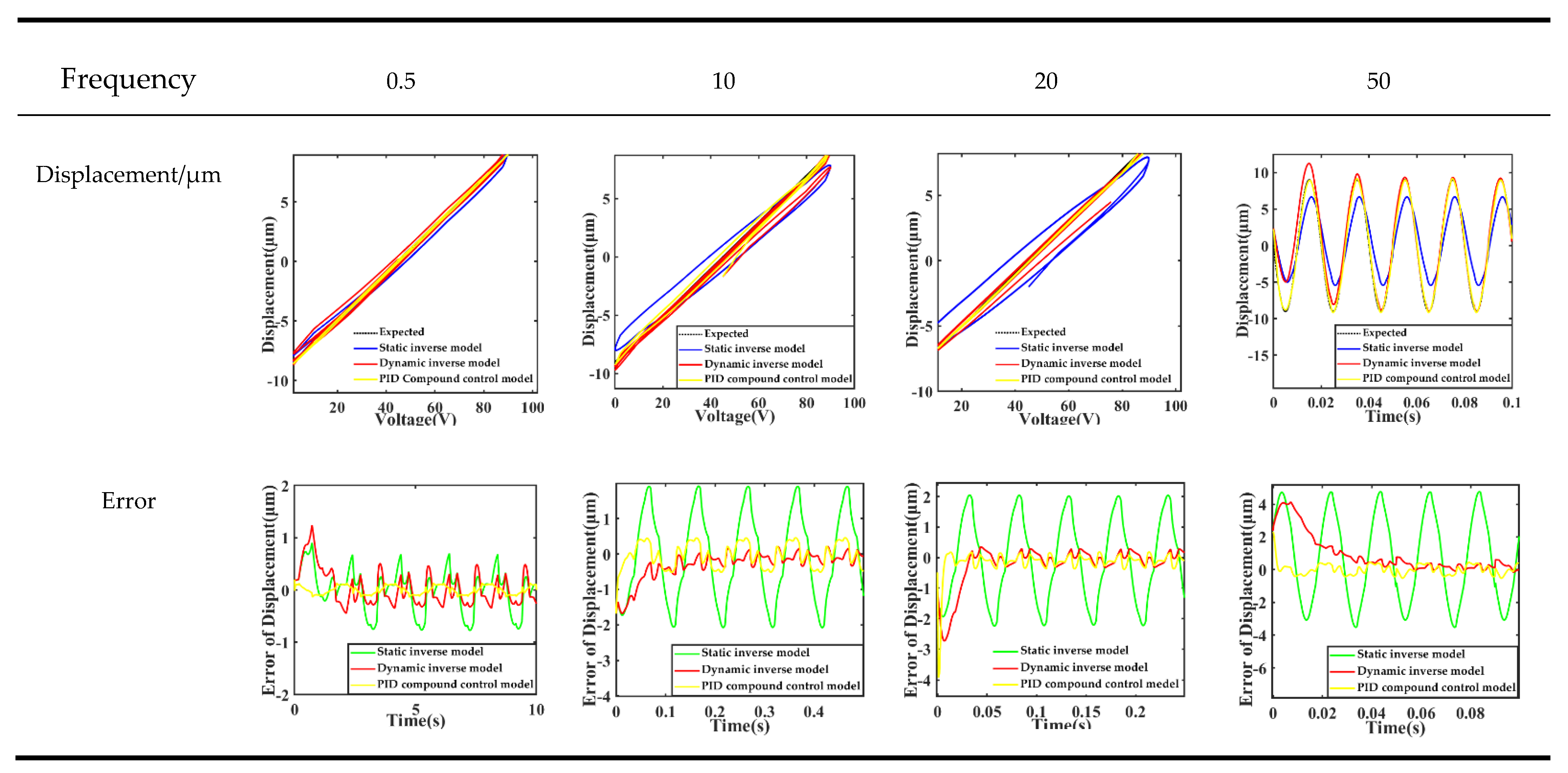
5. Result and Discussion

For this paper, a structure-integrated piezoelectric sensor-actuator and its control system are designed and built. The static model of the output displacement is derived theoretically and the stationary model parameters and the dynamic model are calculated by the system identification. This paper proposed the input–output transfer function. Comparing the different models, we found that it can be concluded from the simulation as follows:
(1) When the frequency increased from 0.5 Hz to 50 Hz, the average fitting error of static hysteresis model increased from 0.027 to 0.187, and for the dynamic hysteresis model from 0.044 to 0.052. The increase for the static inverse model is from 0.316 to 1.248, and for the dynamic inverse model is from 0.27 to 0.464. The results of the average fitting errors showed that the fitting accuracy of the static model is slightly higher than that of the dynamic model at low frequency (0.5 Hz).
(2) The compensation accuracy of the dynamic model is obviously better than that of the static model with the increase of frequency, and the fitting accuracy of the dynamic inverse model is always better than that of the static inverse model in the range of 0.5 to 50 Hz.
(3) Based on the dynamic inverse model, the average error of piezoelectric sensor-actuator is reduced from 0.270 to 0.071, and the root mean square error is reduced from 0.337 to 0.079 when the input frequency is 0.5 Hz. The root mean square error of the system output displacement is reduced from 1.052 to 0.250, which is about ¼ of the original. This shows that the piezoelectric sensor-actuator control system designed for this paper can basically realize the input–output control of the sensor-actuator.
In summary, the accuracy of the static model is greater than that of the dynamic model when the frequency is 0.5 Hz but the case is obviously opposite beyond 0.5 Hz. This is consistent with the discussion in the theoretical part. However, for the inverse model, the accuracy of the dynamic model is always higher than that of the static model, which shows that the hysteresis characteristics of piezoelectric stacks are nonlinear and are greatly affected by the frequency. In the application background of industrial machinery, the frequency is usually greater than 0.5 Hz. Therefore, comparing with the static model, the dynamic model proposed in this paper obviously has higher accuracy and wider applicable bandwidth.
This structure-integrated sensor-actuator makes full use of the characteristics of piezoelectric materials such as fast response rate. Meanwhile, it can collect deformation signals and control the output of the actuator in real time. This means that we can improve the response rate and accuracy of the system and solve the problem of interference between two signals for function-integrated sensor-actuators.

6. Conclusions

As shown in our results, the dynamic model can improve the accuracy of sensor-actuators with the increase of frequency and broaden the available bandwidth of the systems. When combined with the PID control presented in this paper, the root mean square error of the system output displacement is reduced by about one-quarter of the original, which means that the structure-integrated piezoelectric sensor-actuator and its control system could be applied to micro high-precision integrated systems such as medical manipulators and end-effectors for industrial robots. The structure implemented solved the sensing and actuating function problems at the same time.

Author Contributions

All the authors have made great contributions to the design of the system. X.S. and J.F. supervised the experimental measurements and the writing of the manuscript. H.S. and H.C. designed and processed the structure, performed the experiment, analyzed the data, and wrote the paper. L.Z. and X.Z. provided valuable suggestions and comments on the interpretation of results and on the paper. All authors have read and agreed to the published version of the manuscript.

Funding

This work is supported by the National Key R&D Program of China under Grant No. 2018YFB1308500.

Institutional Review Board Statement

Not applicable.

Informed Consent Statement

Not applicable.

Data Availability Statement

Not applicable.

Conflicts of Interest

The authors declare no conflict of interest.

Nomenclature

xthe displacement of the actuator
S3the strain of the piezoelectric stack
T3stress
d33piezoelectric constant
E3external electric field
S 33 E short circuit elastic compliance coefficient with constant electric field
hthe thickness of a single piezoelectric ceramic sheet
nthe number of layers of piezoelectric laminated ceramics
lthe length of the piezoelectric ceramic sheet
bthe width of the piezoelectric ceramic sheet
Foutthe direction output force of piezoelectric stack
uathe drive voltage of the piezoelectric stack
kampseries circuit of gain
Rresistance
Cacapacitors
ucthe output voltage of driving amplifier
qthe charge produced by quartz
Athe area of the piezoelectric quartz
εrthe relative permittivity of quartz
ε0the dielectric constant of air
mthe equivalent mass of moving part of piezoelectric sensor-actuator system
cfthe equivalent viscosity coefficient of actuator structure
kfthe stiffness coefficient of actuator
kathe equivalent stiffness of preload

References

  1. Hao, Y.; Wang, T.; Xie, Z.; Sun, W.; Liu, Z.; Fang, X.; Yang, M.; Wen, L. A eutectic-alloy-infused soft actuator with sensing, tunable degrees of freedom, and stiffness properties. J. Micromech. Microeng. 2018, 28, 024004. [Google Scholar] [CrossRef] [Green Version]
  2. Di Rito, G.; Chiarelli, M.R.; Luciano, B. Dynamic Modelling and Experimental Characterization of a Self-Powered Structural Health-Monitoring System with MFC Piezoelectric Patches. Sensors 2020, 20, 950. [Google Scholar] [CrossRef] [PubMed] [Green Version]
  3. Chen, L.; Weng, M.; Zhou, P.; Huang, F.; Liu, C.; Fan, S.; Zhang, W. Graphene-Based Actuator with Integrated-Sensing Function. Adv. Funct. Mater. 2019, 29, 1806057. [Google Scholar] [CrossRef]
  4. Sun, G.; Hu, Y.; Dong, M.; He, Y.; Yu, M.; Zhu, L. Posture measurement of soft pneumatic bending actuator using optical fibre-based sensing membrane. Ind. Robot Int. J. Robot. Res. Appl. 2019, 46, 118–127. [Google Scholar] [CrossRef]
  5. Oh, H.; Dayeh, S.A. Physics-Based Device Models and Progress Review for Active Piezoelectric Semiconductor Devices. Sensors 2020, 20, 3872. [Google Scholar] [CrossRef] [PubMed]
  6. He, J.P.; Huo, Q.; Li, Y.H.; Wang, K.; Zhu, M.C.; Xu, Z.B. Neural network control of space manipulator based on dynamic model and disturbance observer. IEEE Access 2019, 7, 130101–130112. [Google Scholar]
  7. Zeng, X.; Wang, J.; Song, P.; Huang, S. A novel piezoelectric micro-gripper’s control based on modified smith predictor. In Proceedings of the 2017 International Conference on Electronic Industry and Automation; Babaei, E., Reig, C., Sung, W.T., Eds.; Atlantis Press: Paris, France, 2017; Volume 145, pp. 277–281. [Google Scholar]
  8. Gonzalez, C.; Lumia, R. An IPMC microgripper with integrated actuator and sensing for constant finger-tip displacement. Smart Mater. Struct. 2015, 24, 24. [Google Scholar] [CrossRef]
  9. Rakotondrabe, M.; Ivan, I.A.; Khadraoui, S.; Lutz, P.; Chaillet, N. Simultaneous Displacement/Force Self-Sensing in Piezoelectric Actuators and Applications to Robust Control. IEEE/ASME Trans. Mechatron. 2014, 20, 519–531. [Google Scholar] [CrossRef] [Green Version]
  10. Boukabache, H.; Escriba, C.; Fourniols, J.-Y. Toward Smart Aerospace Structures: Design of a Piezoelectric Sensor and Its Analog Interface for Flaw Detection. Sensors 2014, 14, 20543–20561. [Google Scholar] [CrossRef] [Green Version]
  11. Zhang, Z.; Kan, J.W.; Wang, S.; Wang, H.; Ma, J.; Jiang, Y. Development of a self-sensing piezoelectric pump with a bimorph transducer. J. Intell. Mater. Syst. Struct. 2015, 27, 581–591. [Google Scholar] [CrossRef]
  12. Lee, H.; Park, H.; Park, K.K.; Yi, H. Park Application of Adaptive Wave Cancellation Underwater to a Piezoelectric-Material-Based Multilayer Sensor. Sensors 2019, 20, 134. [Google Scholar] [CrossRef] [PubMed] [Green Version]
  13. Varanis, M.; Silva, A.; Mereles, A.; Pederiva, R. MEMS accelerometers for mechanical vibrations analysis: A comprehensive review with applications. J. Braz. Soc. Mech. Sci. Eng. 2018, 40, 527. [Google Scholar] [CrossRef]
  14. Rathod, V.T. A Review of Electric Impedance Matching Techniques for Piezoelectric Sensors, Actuators and Transducers. Electronics 2019, 8, 169. [Google Scholar] [CrossRef] [Green Version]
  15. El Rifai, O.; Aumond, B.; Youcef-Toumi, K. Imaging at the nano-scale. In Proceedings of the 2003 IEEE/ASME International Conference on Advanced Intelligent Mechatronics (AIM 2003); Institute of Electrical and Electronics Engineers (IEEE): Piscataway, NJ, USA, 2004; Volume 2, pp. 715–722. [Google Scholar]
  16. Gan, J.; Zhang, X. A review of nonlinear hysteresis modeling and control of piezoelectric actuators. AIP Adv. 2019, 9, 040702. [Google Scholar] [CrossRef] [Green Version]
  17. Hu, H.; Ben Mrad, R. On the classical Preisach model for hysteresis in piezoceramic actuators. Mechatronics 2003, 13, 85–94. [Google Scholar] [CrossRef]
  18. Mayergoyz, I.; Friedman, G. Generalized Preisach model of hysteresis. IEEE Trans. Magn. 1988, 24, 212–217. [Google Scholar] [CrossRef]
  19. Chen, Y.; Huang, Q.; Wang, H.; Qiu, J. Hysteresis modeling and tracking control for piezoelectric stack actuators using neural-Preisach model. Int. J. Appl. Electromagn. Mech. 2019, 61, 445–459. [Google Scholar] [CrossRef]
  20. Luo, Y.; Qu, Y.; Zhang, Y.; Xu, M.; Xie, S.; Zhang, X. Hysteretic modeling and simulation of a bilateral piezoelectric stack actuator based on Preisach model. Int. J. Appl. Electromagn. Mech. 2019, 59, 271–280. [Google Scholar] [CrossRef]
  21. Bernard, Y.; Maalej, A.H.; Lebrun, L.; Ducharne, B. Preisach modelling of ferroelectric behaviour. Int. J. Appl. Electromagn. Mech. 2007, 25, 729–733. [Google Scholar] [CrossRef]
  22. Tan, U.-X.; Latt, W.T.; Shee, C.Y.; Riviere, C.N.; Ang, W.T. Feedforward Controller of Ill-Conditioned Hysteresis Using Singularity-Free Prandtl–Ishlinskii Model. IEEE/ASME Trans. Mechatron. 2009, 14, 598–605. [Google Scholar] [CrossRef] [Green Version]
  23. Al Janaideh, M.; Rakheja, S.; Su, C.-Y. A generalized Prandtl–Ishlinskii model for characterizing the hysteresis and saturation nonlinearities of smart actuators. Smart Mater. Struct. 2009, 18, 18. [Google Scholar] [CrossRef]
  24. Al Janaideh, M.; Aljanaideh, O. Further results on open-loop compensation of rate-dependent hysteresis in a magnetostrictive actuator with the Prandtl-Ishlinskii model. Mech. Syst. Signal Process. 2018, 104, 835–850. [Google Scholar] [CrossRef]
  25. Gu, G.; Zhu, L. High-speed tracking control of piezoelectric actuators using an ellipse-based hysteresis model. Rev. Sci. Instrum. 2010, 81, 85104. [Google Scholar] [CrossRef] [PubMed]
  26. Gu, G.-Y.; Li, C.-X.; Zhu, L.-M.; Su, C.-Y. Modeling and Identification of Piezoelectric-Actuated Stages Cascading Hysteresis Nonlinearity with Linear Dynamics. IEEE/ASME Trans. Mechatron. 2015, 21, 1792–1797. [Google Scholar] [CrossRef]
  27. Gu, G.-Y.; Yang, M.-J.; Zhu, L.-M. Real-time inverse hysteresis compensation of piezoelectric actuators with a modified Prandtl-Ishlinskii model. Rev. Sci. Instrum. 2012, 83, 065106. [Google Scholar] [CrossRef] [PubMed]
  28. Jiang, H.; Ji, H.; Qiu, J.; Chen, Y. A modified prandtl-ishlinskii model for modeling asymmetric hysteresis of piezoelectric actuators. IEEE Trans. Ultrason. Ferroelectr. Freq. Control. 2010, 57, 1200–1210. [Google Scholar] [CrossRef]
  29. Banks, H.T.; Kurdila, A.J.; Webb, G. Identification of hysteretic control influence operators representing smart actuators part I: Formulation. Math. Probl. Eng. 1997, 3, 287–328. [Google Scholar] [CrossRef]
  30. Goldfarb, M.; Celanovic, N. Modeling piezoelectric stack actuators for control of micromanipulation. IEEE Control Syst. 1997, 17, 69–79. [Google Scholar] [CrossRef]
  31. Chen, J.; Peng, G.; Hu, H.; Ning, J. Dynamic Hysteresis Model and Control Methodology for Force Output Using Piezoelectric Actuator Driving. IEEE Access 2020, 8, 205136–205147. [Google Scholar] [CrossRef]
  32. Li, K.; Yang, Z.; Lallart, M.; Kwok, N.M.; Chen, Y.; Liu, H. Hybrid hysteresis modeling and inverse model compensation of piezoelectric actuators. Smart Mater. Struct. 2019, 28, 115038. [Google Scholar] [CrossRef]
  33. Ang, W.T.; Khosla, P.K.; Riviere, C.N. Feedforward controller with inverse rate-dependent model for piezoelectric actuators in trajectory-tracking applications. IEEE/ASME Trans. Mechatron. 2007, 12, 134–142. [Google Scholar] [CrossRef] [Green Version]
  34. Yi, S.; Yang, B.; Meng, G. Ill-conditioned dynamic hysteresis compensation for a low-frequency magnetostrictive vibration shaker. Nonlinear Dyn. 2019, 96, 535–551. [Google Scholar] [CrossRef]
  35. Davoodi, A.A.; Izadi, I.; Ghaisary, J. Design and Implementation of a Feedforward Feedback Controller for a Piezoelectric Actuator. In Proceedings of the 2019 27th Iranian Conference on Electrical Engineering (ICEE); Institute of Electrical and Electronics Engineers (IEEE): Piscataway, NJ, USA, 2019; pp. 1070–1074. [Google Scholar]
  36. Saleem, A.; Al Hattali, M.; Shafiq, M.; Bahadur, I. Tracking Control of Piezoelectric Actuators using Feedforward/Feedback Learning-based Controller. In Proceedings of the 2019 6th International Conference on Control, Decision and Information Technologies (CoDIT); Institute of Electrical and Electronics Engineers (IEEE); Piscataway, NJ, USA, 2019; pp. 1981–1985. [Google Scholar]
  37. Bichurin, M.I.; Petrov, V.; Petrov, R. Direct and inverse magnetoelectric effect in layered composites in electromechanical resonance range: A review. J. Magn. Magn. Mater. 2012, 324, 3548–3550. [Google Scholar] [CrossRef]
  38. Al Janaideh, M.; Rakotondrabe, M. On hysteresis modeling of a piezoelectric precise positioning system under variable temperature. Mech. Syst. Signal Process. 2020, 145, 106880. [Google Scholar] [CrossRef]
Figure 1. The structure of the piezoelectric sensor-actuator.
Sensors 21 00269 g001
Figure 2. The prototype of the piezoelectric sensor-actuator.
Sensors 21 00269 g002
Figure 3. The dynamical model of the piezoelectric sensor-actuator.
Sensors 21 00269 g003
Figure 4. Experimental schematic diagram.
Sensors 21 00269 g004
Figure 5. Hysteresis curve of piezoelectric sensor-actuator.
Sensors 21 00269 g005
Figure 6. Dynamic Prandtl–Ishlinskii model.
Sensors 21 00269 g006
Figure 7. The error between output displacement and ideal output displacement.
Sensors 21 00269 g007
Figure 8. Control system structure with inverse model feedforward and feedback.
Sensors 21 00269 g008
Figure 9. The results of displacement of different control systems.
Sensors 21 00269 g009
Table 1. The parameters of the PZT.
ComponentMaterialElastic Modulus (GPa)Poisson RatioDensity ρ (kg/m3)
Piezoelectric stackPZT-5540.347600
Quartz waferx-quartz0.172650
Sensor housingsteel2060.257900
Package cavityaluminum720.332810
Fixed seataluminum720.332810
Thrust baraluminum720.332810
Table 2. Error of hysteresis model under different excitation signal frequencies.
Frequency of Input Signal/Hz.0.5102050
Errors
Maximum error of static model0.065290.244790.276720.29893
Average error of static model0.027070.076150.099840.18748
Root mean square error of static model0.033940.086340.112560.20978
Maximum error of dynamic model0.126780.176870.155770.78268
Average error of dynamic model0.044340.046140.040960.05255
Root mean square error of dynamic model0.059400.052880.047460.08927
Table 3. Errors of the hysteresis inverse model under different excitation signal frequencies.
Frequency of Input Signal/Hz.0.5102050
Errors
Maximum error of static inverse model0.901162.082092.241394.76271
Average error of static inverse model0.316380.283820.309301.24777
Root mean square error of static inverse model0.402790.637550.700531.99596
Maximum error of dynamic inverse model1.238271.683362.732864.13814
Average error of dynamic inverse model0.270030.082090.087250.46418
Root mean square error of dynamic inverse model0.337450.250770.336721.05211
Table 4. The calculated output displacement error of different control systems.
Input Signal Frequency /Hz0.5102050
Maximum error0.200941.683363.924992.28057
Averahe error0.071360.075450.050280.13326
Root mean square error0.079980.178400.224150.24960
Publisher’s Note: MDPI stays neutral with regard to jurisdictional claims in published maps and institutional affiliations.

