1. Introduction
One of the critical tasks in the industry is diagnostics of the state and dynamic structural monitoring of constructions in a multilayer media to ensure their reliability and safe operation [
1]. At the same time, the features of wave propagation in layered media, multiple reflections of disturbances from the boundaries of layers make such problems very difficult to interpret. Instrumental support of dynamic tests of buried objects is inevitably associated with the solution of dynamic problems of wave propagation and assessment of the stress-strain state of structures under various influences.
Problems of the dynamics of layered media have long attracted the attention of researchers. Many concepts of strength have changed with the advent of laminates. Damascus steels used to make weapons have excellent toughness and cutting properties due to their layered structure. Bulletproof vests are made of composite laminates and revolutionized personal firearm protection.
The geophysical structure of the Earth’s surface makes it possible to formulate the problems of the dynamics of buildings and structures lying on layered media under seismic influences. The dynamic behavior of buildings and structural elements under seismic influences are considered in the works of Terenzi et al. [
2], Di Lorenzo et al. [
3], and Sabino et al. [
4].
At the same time, it is being improved as an instrumental base for digital measurements (Li Zhu et al. [
5], Xiao-Wei Ye et al. [
6]), and methods of signal processing and analysis. Anaissi et al. [
7] presented a new algorithm for detecting and assessing damage in bridge structures. This technique uses tensor analysis to combine data and feature extraction, and additionally uses one-class support vector machines to detect structural damage. The indirect boundary element method was proposed by Ba et al. [
8] to study three-dimensional (3D) dynamic responses of a two-dimensional (2D) hill in a layered elastic half-space subject to obliquely incident waves. The proposed method is applied to construct a scattered field in closed areas.
The spatial problem (3D) of the dynamic interaction of the soil structure was investigated by Hana et al. [
9] using a model of a system with several degrees of freedom on a cylindrical rigid foundation embedded in a layered fluid-saturated poroelastic half-space using the indirect boundary element method (IBEM).
An efficient method for calculating layered composite materials was proposed in [
10,
11] based on the contact layer model.
The problems of non-destructive testing (NDT) and monitoring of the state of structures of engineering structures, such as oil and gas pipelines, rails, aircraft components, and adhesive joints, are considered in the work of Lugovtsova [
12]. Modeling and analysis of wave propagation and their interaction with damage due to dispersion and multimodal nature was carried out on the basis of the finite element method with a scaled boundary. The results obtained made it possible to analyze the propagation of waves in multilayer structures and are important for the further development of non-destructive testing of engineering structures consisting of several layers.
The dynamics of layered structures is effectively used in the analysis of the stability of landslide slopes. In the works of Zhan et al. [
13], the behavior of landslide slopes under the action of dynamic loads was considered. Experimental studies by Zou et al. [
14] made it possible to simulate the behavior of bridge elements with different peak accelerations. Evaluation of the behavior of earthen dams was performed by Cai et al. [
15]. The design and analysis of the destruction of sand structures was carried out by Zhou [
16] to study their stability under dynamic loads. Using nonlinear and machine learning methods, i.e., grouped data processing (GMDH) and multivariate adaptive regression spline (MARS), two models were applied and developed to predict slope deformation in earth dams for different types of earthquakes. An analytical solution was presented by Guo [
17] based on a limit equilibrium analysis.
The influence of geological factors of the coal seam on the initiation pressure and crack propagation under dynamic impacts was studied by Cao et al. [
18]. As a result of theoretical analysis, a model was created for calculating pressure on a multilayer coal seam based on the fracture criterion in the theory of maximum tensile stress.
Analysis of the dynamic response of heterogeneous layered media with the aim of developing a method of NDT and determining their mechanical and strength characteristics was carried out in [
19,
20]. A comprehensive diagnostic method was proposed in [
21] based on the analysis of the unsteady response of a multilayer structure, on the surface of which a shock load acts. During the solution procedure, various methods of genetic algorithms are used which have shown good results. The NDT method (Bertocci et al. [
22]), based on scanning acoustic microscopy, for damage detection becomes very useful for detecting defects in multilayer structures with a thickness of several microns, providing a low time investment (limitation for other NDT methods) and quantitative analysis based on measurements.
Some problems of nonstationary dynamics are solved by direct methods using numerical analysis. Kuvat et al. [
23] applied methods for determining the dynamic properties of mixtures of sand and bitumen, which can be used as damping materials in the foundations of building structures. In cyclic tests, the influence of the content and properties of bitumen on the ability to absorb energy was studied.
The design of buildings and structures under dynamic loads from moving vehicles is considered in the works of Zhou et al. [
24] and Ai et al. [
25]. Sun et al. [
26] noted that high-performance roads require a reliable tool that can calculate the structural response caused by moving vehicles. Models based on the method of spectral elements are proposed for efficiently predicting the three-dimensional dynamic response of layered systems under a moving load. The study of the dynamic characteristics of a layered poroelastic soil lying under an uneven pavement exposed to traffic loads was carried out by Lyu et al. [
27]. The pavement layer is modeled as a thin Kirchhoff plate, while the underlying base and substrate are treated as a saturated two-layer poroelastic medium. A numerical verification of the proposed models allows one to accurately predict the dynamic response of layered systems caused by a moving load.
Algorithms for artificial intelligence and creation of a neural network were developed in the articles by Beskopylny et al. [
28] and Lyapin [
29] based on direct algorithms for solving (Lyapin et al. [
30]). The data of the response of the time domain of the multilevel structure to the diagnostic shock load are used as input information. This approach provides a tool for restoring the elastic properties of layers according to the corresponding thickness coordinates.
The above analysis of the literature shows that many problems of the dynamics of multilayer media are very relevant, are of great practical importance, and are solved either numerically or experimentally. At the same time, the dynamic features of wave reflections from the boundaries of media and the resonance properties of objects can be determined with great difficulty from the numerical or experimental analysis. In addition, in the process of designing a sensor system, frequency-dependent characteristics of the environment appear, leading to nonlinear responses and complicating data analysis. Thus, the purpose of this article is to construct an analytical method that allows simulating dynamic effects in layered media, as well as obtaining fundamental solutions, identifying resonance zones and features of the dynamic response of a structure using the example of underground structures.
2. Analytical Approach to the Problem of the Underground Object Dynamics in a Layered Medium
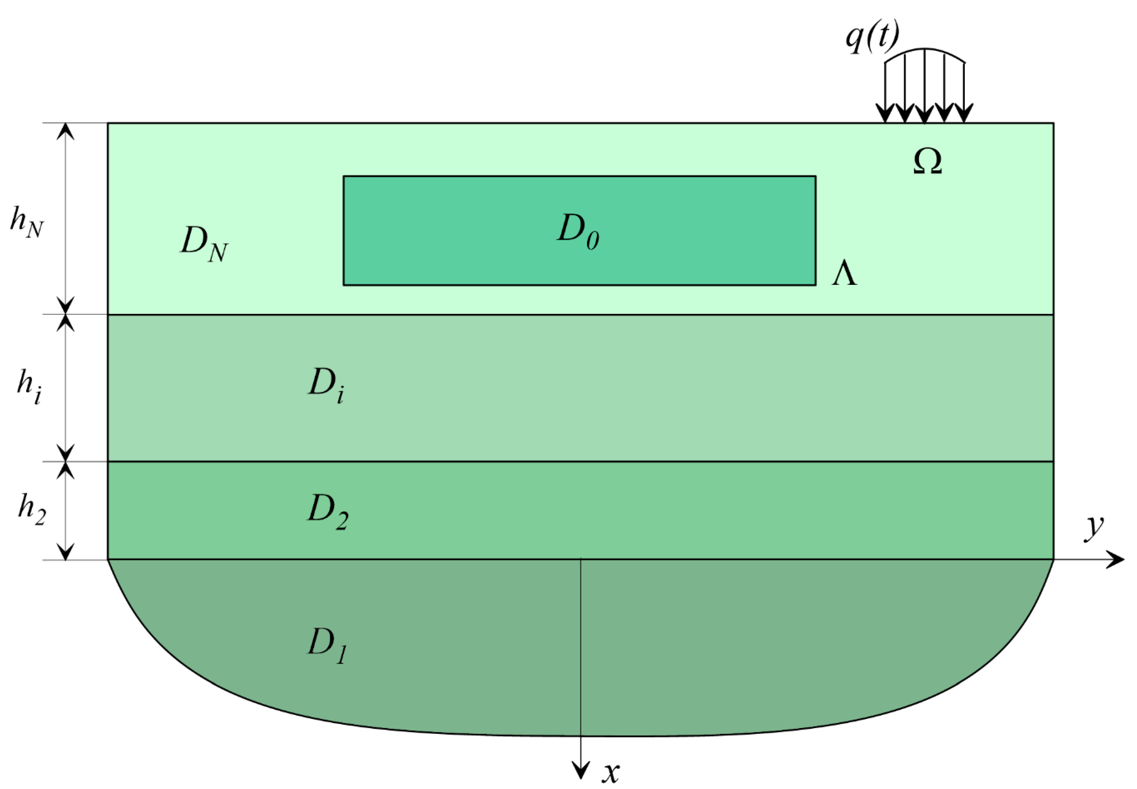
Let us consider the area occupied by a linear elastic (viscoelastic) medium, which is a multilayer half-space, under the surface of which an underground structure of arbitrary shape is located (
Figure 1).
A multilayer half-space consists of a set of layers where is occupied by the half-space. is jth layer (j = 2, …, N); and is the area occupied by an underground structure.
The physical properties of the medium are described by the density and propagation velocities of transverse and longitudinal waves .
The conditions for joining dissimilar layers are considered rigid with the requirement of continuity of the vectors of displacements and stresses when passing through the interface.
Without limiting generalization, rigid connection conditions can be changed to homogeneous frictionless contact conditions including continuity of normal displacements and absence of tangential stresses as well as Coulomb friction.
On the surface of the medium outside the structure in a limited area , a system of forces oscillating with a frequency is set.
The wave fields for the displacements of the foundation points and the layered medium are described by integral representations (1) obtained on the basis of the dynamic reciprocity theorem
The components of the displacement vector at the boundary of the final body (structure) and the stress vector in the area of joining the structure with the layered foundation are unknown. Functions describing stresses and displacements at a point for a homogeneous plane with a source are selected as fundamental solutions for the region .
For a layered foundation, the matrices of fundamental solutions
are implemented using the superposition principle. This construction of a solution for a multilayer medium is based on the derivation of constitutive relations for one layer with stress vectors specified on its faces [
26].
Let, in the local coordinate system for the
jth layer
, the amplitude functions of displacements under the action of a lumped source
have the form
The functions
satisfying the equations of motion, according to the proposed method are sought in the form
In a similar consideration of the half-plane, we assume .
Here,
, the terms of this representation, are solutions of the Lamé equations for a homogeneous half-plane satisfying the boundary conditions
We represent the displacement vector
in the form of a Fourier integral through the transformants of the stress vector
The contour is determined by the principle of limiting absorption: it bypasses the positive poles of the integrand from below, negative from above, and coincides with the real axis in the rest of the part.
Matrix components
are given in
Appendix A and depend on relative frequencies
, where
are the wave speeds for corresponding medium.
To take into account the viscoelastic properties of the medium, the loss tangents are introduced for longitudinal and shear waves , equal to ratio of imaginary parts of relative frequencies squares to real ones . In this case, contour equals the real axis completely.
Similar to formula (5), the displacements for the half-plane
through functions
are determined, where the elements
satisfy the relations
is the Kronecker symbol.
Determining the stress state of the layer as the sum of the corresponding solutions for two half-planes, we obtain
where
are given in
Appendix B.
For the second group of terms, we find
The functions
determine displacements in a homogeneous plane with the parameters of the layer under consideration from the action of a concentrated source of oscillations
in the form of a set of cylindrical waves and correspond to the components of the matrix
Using the decomposition formulas, they can be written in the Fourier transform form
The form of functions
is given in
Appendix A.
Following the same logics for fundamental solutions for stresses, we get:
in Fourier transformation form are given in
Appendix B.
The introduced Fourier transforms of the stress functions
of representations (2), (7) are unknown and must be determined from the conditions for joining the dissimilar components of the layered half-plane with each other. Satisfying the equalities of the components of the vectors of displacements and stresses when passing through the interfaces between the media in the Fourier transforms, we obtain a system of linear algebraic equations
with unknowns
where
is the general vector of unknown stresses for a multilayer structure.
In the frictionless case and under coupling conditions, the view of matrix
will change. This leads to change in dispersion properties of construction and difference in properties for wave’s refraction and transition through partition boundary which is also presented in [
31,
32]. In particular, for road related constructions, the effects of smooth contact lead to decreasing in structural properties and physically to redistribution of vibration energy to higher frequency area especially in side zones around loading area. Such effect can be used for methods of road coatings quality inspection.
The fundamental solutions obtained in this way have the important property of the absence of stresses on the day surface . This excludes from participation in representations (1) unknown displacements on this part of the boundary of the region .
Letting the point
be further to the boundary of the area occupied by the foundation, we obtain a system of boundary integral equations for the vectors
and
The system of Equations (13) is solved by the method of linear or constant boundary elements with subsequent spline approximation of the obtained distributions of unknown functions and . The centers of boundary elements and docking nodes are chosen as collocation points.
Using the solution to system (13) and subsequent numerical differentiation, the authors consider the concentration of dynamic stresses at the boundary of the foundation depending on its depth and the ratio of the elastic parameters of the foundation layers.
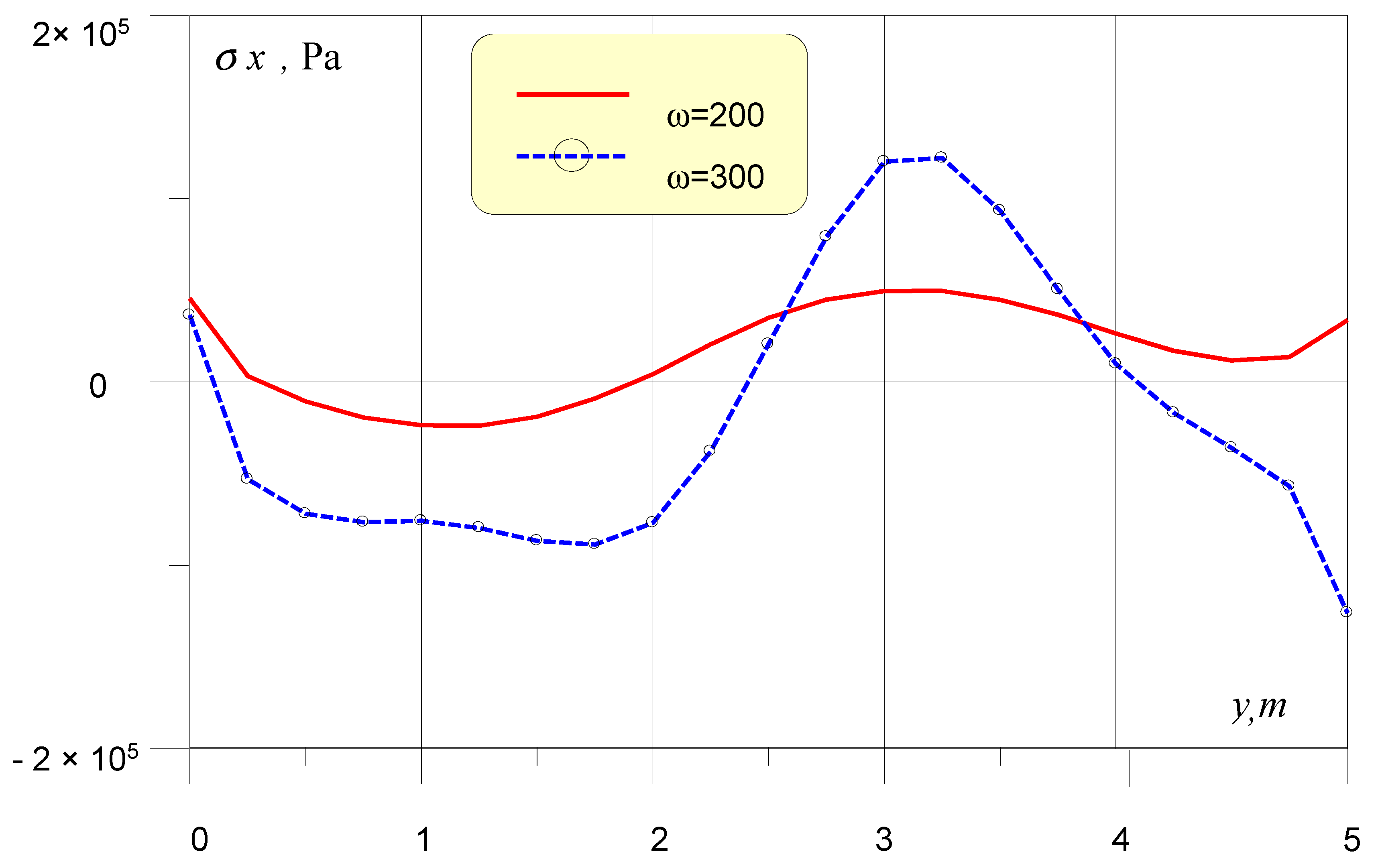
As a computational example,
Figure 2 represents
normal stresses distribution on lower edge of buried by 0.4 m in triple layered foundation of 0.5 m height. The soil foundation structure is supposed to be normal with increasing of wave speeds values along the layers thickness. The dynamic load is created by surface point sources, moved from foundation by 2.5 m and with the level of 100 kN. The plots represent cases of source oscillations with frequencies
= 200 and 300 rad/s. The figure shows that stresses distribution can have areas of equal sign, which leads to bending and rotation of the foundation.
3. Experimental Methods
3.1. Experimental Technique
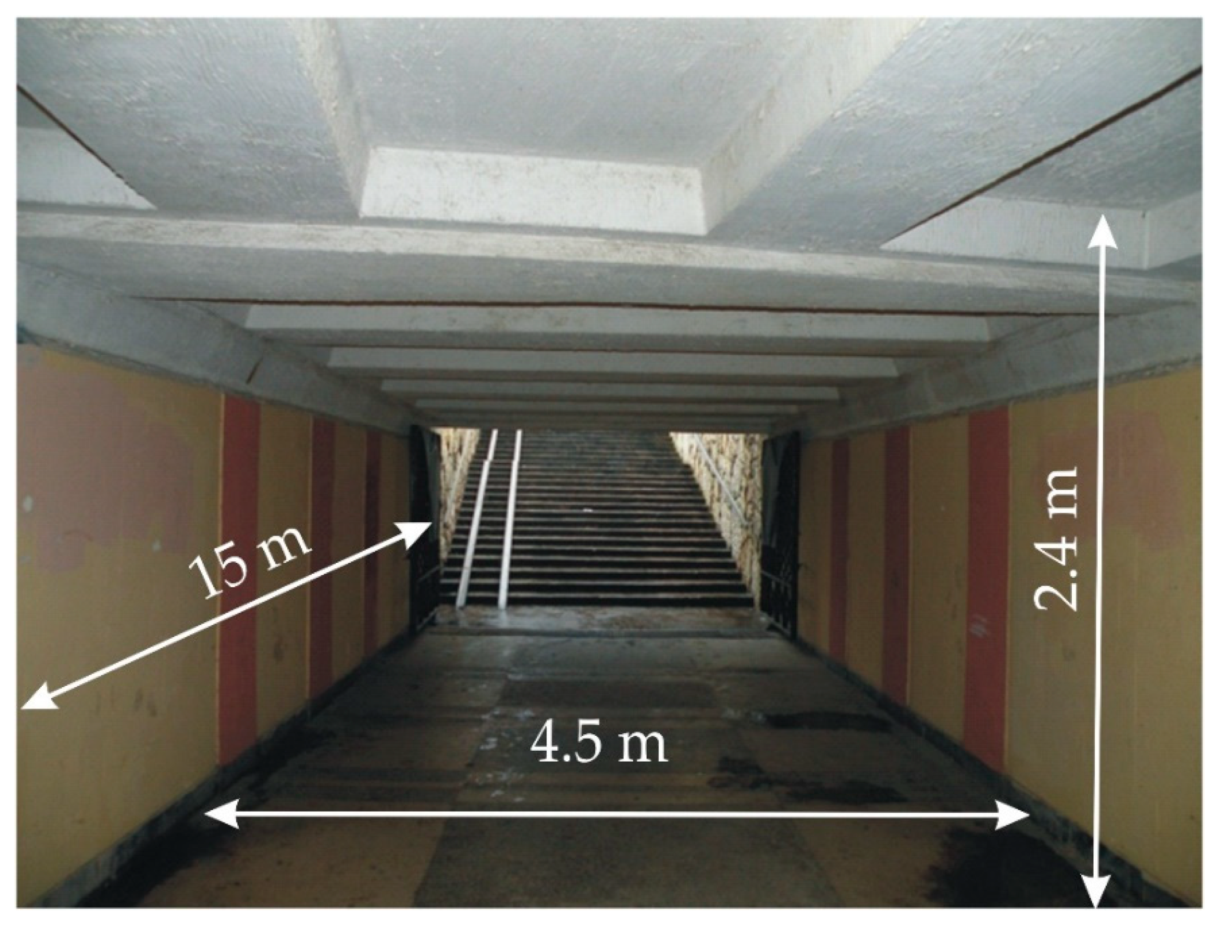
Experimental studies were carried out at an underground pedestrian crossing located in the city center of Rostov-on-Don, Russia. The total volume of the structure is up to 1200 m
3, the depth of the footing is up to 3.8 m, and the depth of occurrence under the carriageway above the upper beams is 0.5 m. The view of the pedestrian crossing is shown in
Figure 3.
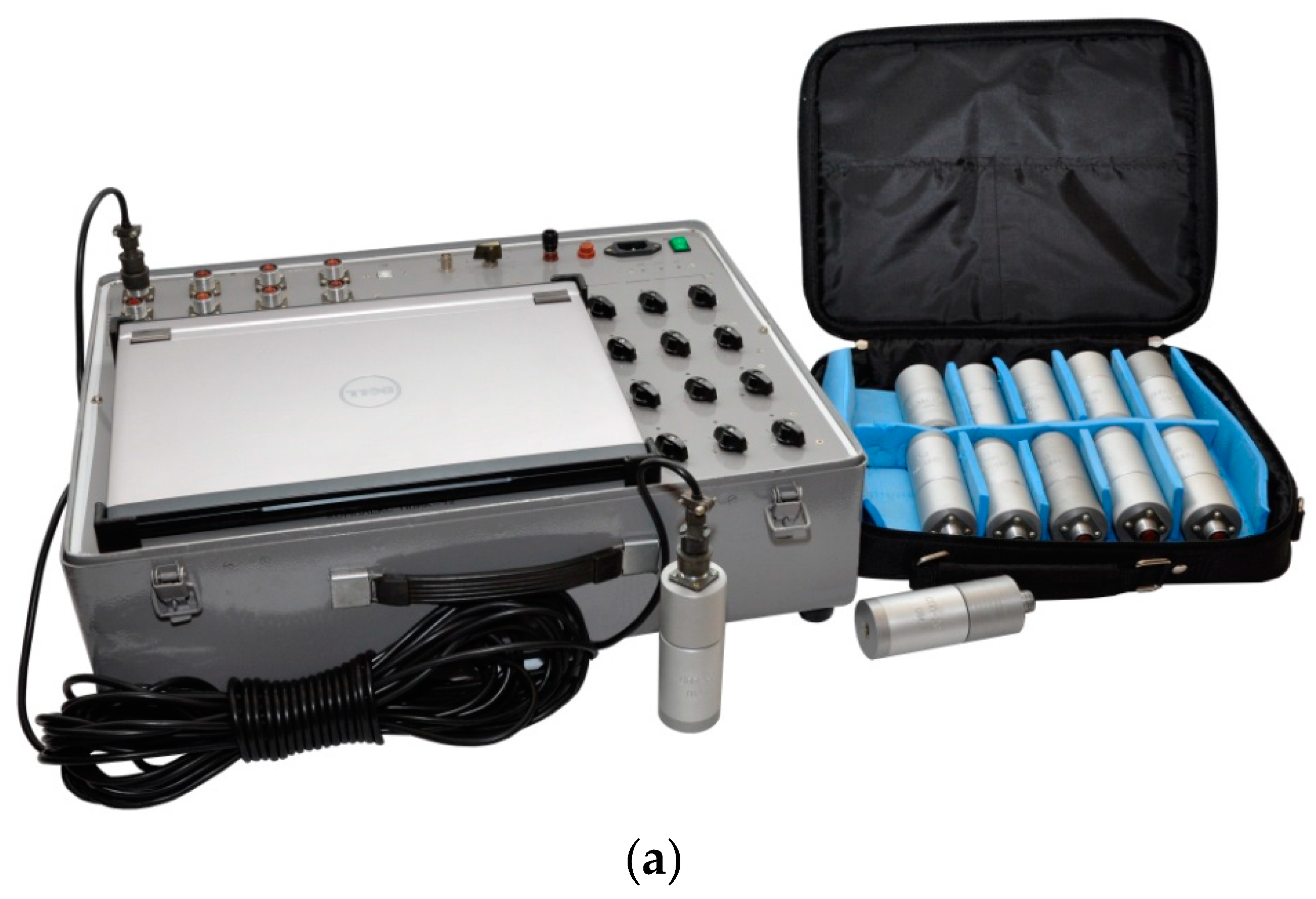
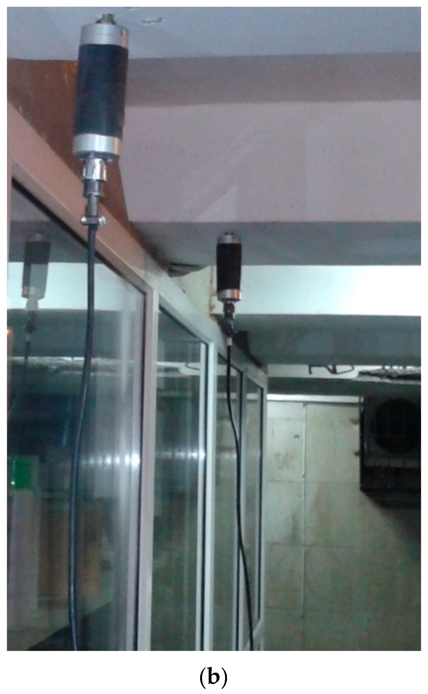
Vibration measuring 12-channel device VK-12 (
Figure 4) is developed and implemented on the basis of the E14–440 module manufactured by the company “L-Card” the level of noise (micro seismic vibrations) and transmission of signals in digital form for further processing in a computer (
Table 1).
During experimental studies, the accelerometers sensors were fixed in the center of the ceilings using anchor bolts. This type of fastening provides the best match between the sensor and the overlap.
During experimental studies, the level of vibration velocities from the following sources was investigated:
- (1)
passage of a KamAZ vehicle weighing 20.5 tons at a speed of 30 km/h;
- (2)
passage of a KamAZ vehicle weighing 20.5 tons at a speed of 50 km/h;
- (3)
impact on the floor.
Programs for signal processing are based on the transformation of data arrays, and the construction of amplitude–frequency characteristics (AFC) on the basis of the obtained AVX by applying the fast Fourier transform. For a more correct result, for each series of measurements, a correlation analysis was carried out, followed by averaging and smoothing of the results.
Amplitude–frequency characteristics obtained from ABX using fast Fourier transform reflect the integral values of the amplitudes for each of the frequencies, in a given interval of the original signal.
It should also be noted that, when choosing the method of vibrations excitation for evaluating the mechanical properties of surface layers and the structural state of the shallow laying object, it is possible to use effectively such diagnostic installations as falling weight of large mass HWD.
3.2. Results Processing Technique
In accordance with GOST R 52892–2007, the vibration velocities were obtained using the integral Fourier transform to the recorded amplitude–time characteristics of the vibration accelerations. Namely, considering the properties of the Fourier transform, as well as that
, the following dependence is valid
Here,
is the circular frequency of oscillations,
i is the imaginary unit,
A(
t) and
V(
t) are the accelerations and velocities of oscillations,
are the Fourier images of the velocities and accelerations of oscillations, respectively, and
Thus, having registered vibration accelerations, the transition to vibration velocities was carried out by the formula
For the experimental determination of the frequency of natural bending vibrations of the beam, we used the results of recording the vibration accelerations under impact.
The shock impact corresponds to a Gaussian pulse [
31]
Here,
P is the peak value of the shock load and
is the duration of the pulse. The spectrum of a Gaussian pulse is determined by the formula
where
is the circular vibration frequency and
f is the linear vibration frequency.
With a short exposure time, the spectrum of a Gaussian pulse is close to a constant over a wide frequency range.
Under external influence on the structure, the spectrum of the recorded response depends on the spectrum of external influence and the spectral characteristics of the structure. This dependence is expressed by the formula
where
S0 is the response spectrum,
SB is the spectrum of external influences, and
SK is the structure’s own spectrum. Then, the spectrum of the structure is determined by the formula
Thus, it follows from formula (21) that under impact action the response spectrum will differ very little from the structure’s own spectrum.
Since the direct registration of the dynamic response of the structural elements of the transition to an arbitrary dynamic impact is difficult due to the large flow of pedestrians and vehicles, the calculated response spectra from the reference load can be used to assess the impact of an arbitrary non-stationary load on the structural elements. In this study, the impact was taken as a reference effect when a KamAZ vehicle with a mass of 20.5 t passed at speeds of 30 and 50 km/h.
To determine the dynamic response to an arbitrary dynamic action, it is necessary to do the following:
Perform test registration of the response to the dynamic impact under investigation in an arbitrary place (for example, on a road with low traffic volume).
Register the response to the reference action in the same place.
Get the design response by the formula
where
is the spectrum of response rates to the reference impact,
is the spectrum of response rates to the investigated non-stationary impact, and
is the spectrum of response rates to the reference impact recorded on the structural elements of the pedestrian crossing.
4. Results and Discussion
As an example of the application of the proposed calculation method, let us consider the problem of determining the dynamic stresses on the inner boundary of a buried object caused by loads on the day surface of a multilayer medium. The problem is relevant when analyzing the strength and performance of underground structures. One of the approaches to its solution is to establish links between the maximum (peak) voltage values and the maximum values of vibration velocities recorded by sensors at measurement points. When considering the vibrations of beams (slabs) as elements of ground structures, usually GOST R 52892–2007 uses a ratio of the form
where, in accordance with GOST R 52892–2007,
is dynamic modulus of elasticity of the beam;
is the density of the beam material;
is the total weight of the beam, including dead weight
and surface load;
is modal coefficient corresponding to the fundamental mode of vibration, having a value in the range from 1 to 1.33; and
is the maximum value of the vibration velocity along the entire length of the beam
However, the presence of a layered medium, into which a buried object is immersed, does not allow applying this formula directly to underground structures and requires taking into account the processes of wave propagation in inhomogeneous media.
Note also that, when waves propagate in homogeneous media, the relationship between the maximum values of stresses and velocities is preserved. Thus, for the simplest case of wave propagation from a surface lumped oscillating
source of shear in the
direction of
the axis, the displacements have the form
where
is the reduced vibration frequency,
is the Hankel function of the first kind, and
is the shear modulus of the material. Hence, it is easy to show that, for all frequencies with distance
from the source,
.
Thus, in the case of an object immersed in a layered medium, it can be established that
The dimensionless characteristic function depends on the material properties of the components of the layered medium and the thicknesses of the layers , , primarily located above the object.
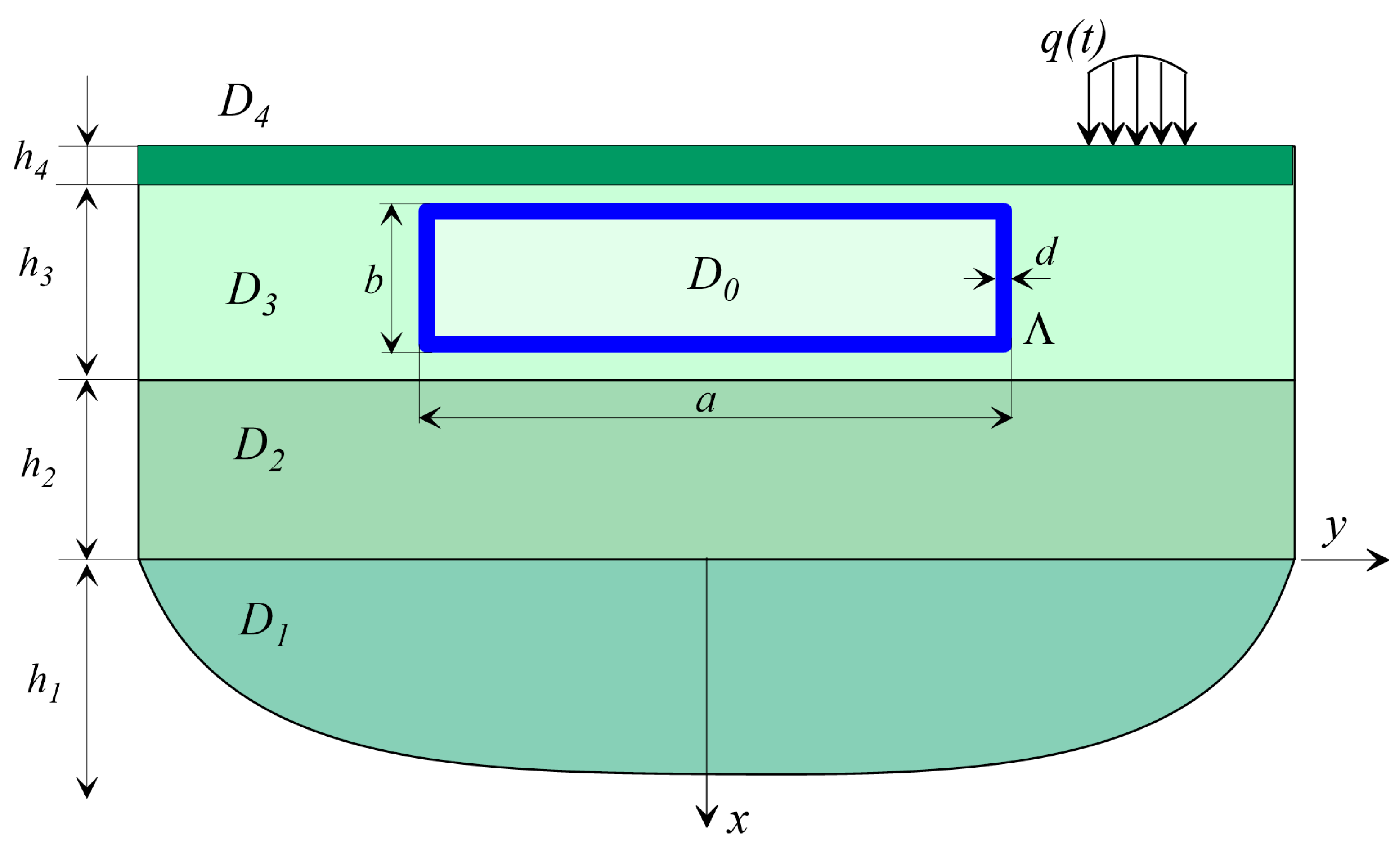
As examples of calculations (
Figure 5), a problem is considered in which an object is located at a depth in Layer 3 and experiences dynamic effects
q(
t).
Figure 6 and
Figure 7 show the dependences
on the parameters of the problem.
4.1. The Underground Object Is Buried in the D3 Layer and the D4 Layer Is Missing
Consider the problem of the dynamics of an underground object located according to the scheme in
Figure 5, when the
D4 layer is absent. The properties of the media (parameters with index 0 refer to an underground facility) are as follows:
E0 = 2 e
4 MPa,
E1 = 100 MPa,
E2 = 80 MPa,
= 2400 kg/m
3,
= 2000 kg/m
3, and
= 1900 kg/m
3. Layer thicknesses are
,
m, and
m. Since there is no
D4 layer,
h4 = 0. Object dimensions are
a = 6 m and
b = 2.5 m. The wall thickness is 0.3 m. Depth of the object is
m.
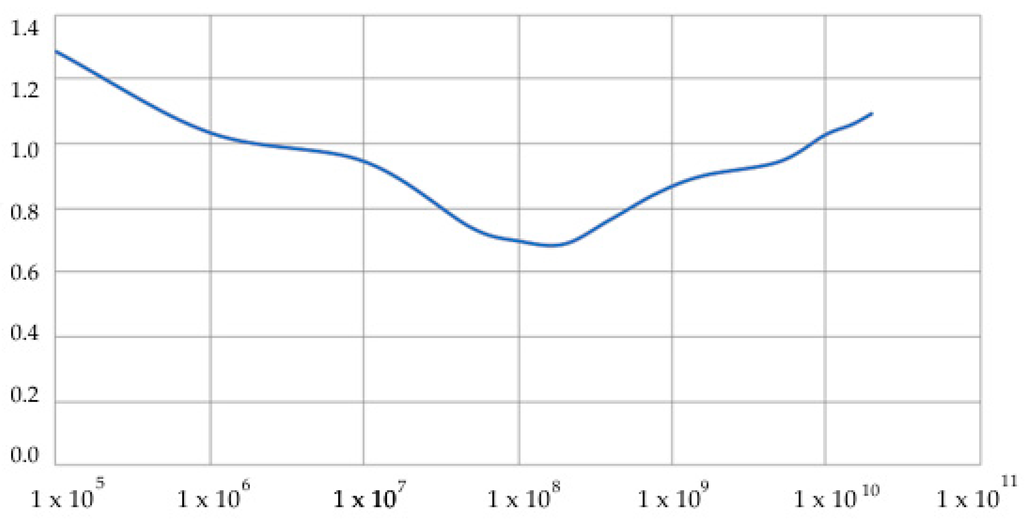
Figure 6 shows the results of calculating the characteristic function
depending on the elastic modulus of the layer in which the object is immersed. A wide range of elastic moduli is considered, from
E = 1 × 10
5 Pa (that is, silty soils) to
E = 1 × 10
10 Pa (granite and harder).
Figure 5 shows that soft layers and very hard layers increase the characteristic function
, and, in the zone of materials corresponding to sandy loams and loams, the characteristic function is close to 1. This makes it possible to effectively use dependence (25) in a wide range of experimental data.
4.2. Underground Object Buried in D3 Layer and D4 Layer Available
Medium properties are as follows: E0 = 2 e4 MPa, E1 = 100 MPa, E2 = 80 MPa, E3 = 200 MPa, = 2400 kg/m3, = 2000 kg/m3, = 1900 kg/m3, and = 2000 kg/m3. Layer thicknesses are , m, m, and m. Object dimensions are a = 6 m and b = 2.5 m. Wall thickness is 0.3 m. Depth of the object is m.
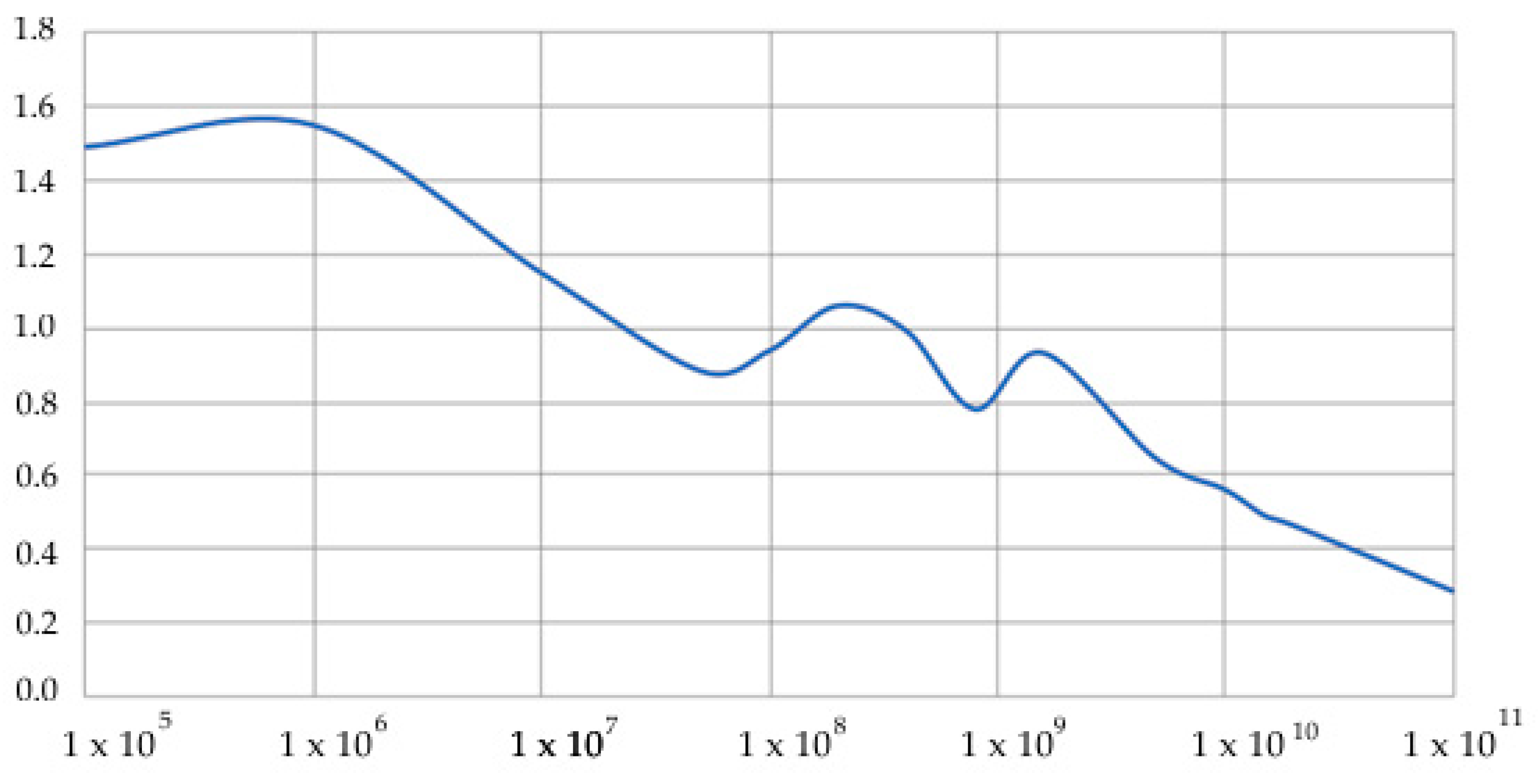
Figure 7 shows the dependence of the characteristic function on the modulus of elasticity of the surface layer
E4; the layer height is conventionally assumed to be 1 m.
Figure 7 shows that, in soft layers, when
E4 of the surface layer
D4 is less than the elastic modulus of the underlying layer
E3, that is,
E4 <<
E3, the characteristic function increases significantly, which is due to resonance phenomena in a layered medium. The upper layer resonates and makes a significant nonlinear contribution to the general picture of the dynamics of a layered medium. If the modulus of elasticity of the near-surface layer
E4 is close to the modulus of the underlying layer
E3, the characteristic function is close to 1. In the case when the rigidity of the surface layer
E4 is greater than the underlying
E3, that is,
E4 >>
E3, the harder layer dampens all resonances, being a kind of low-frequency filter in the system, and the characteristic function drops to 0.3.
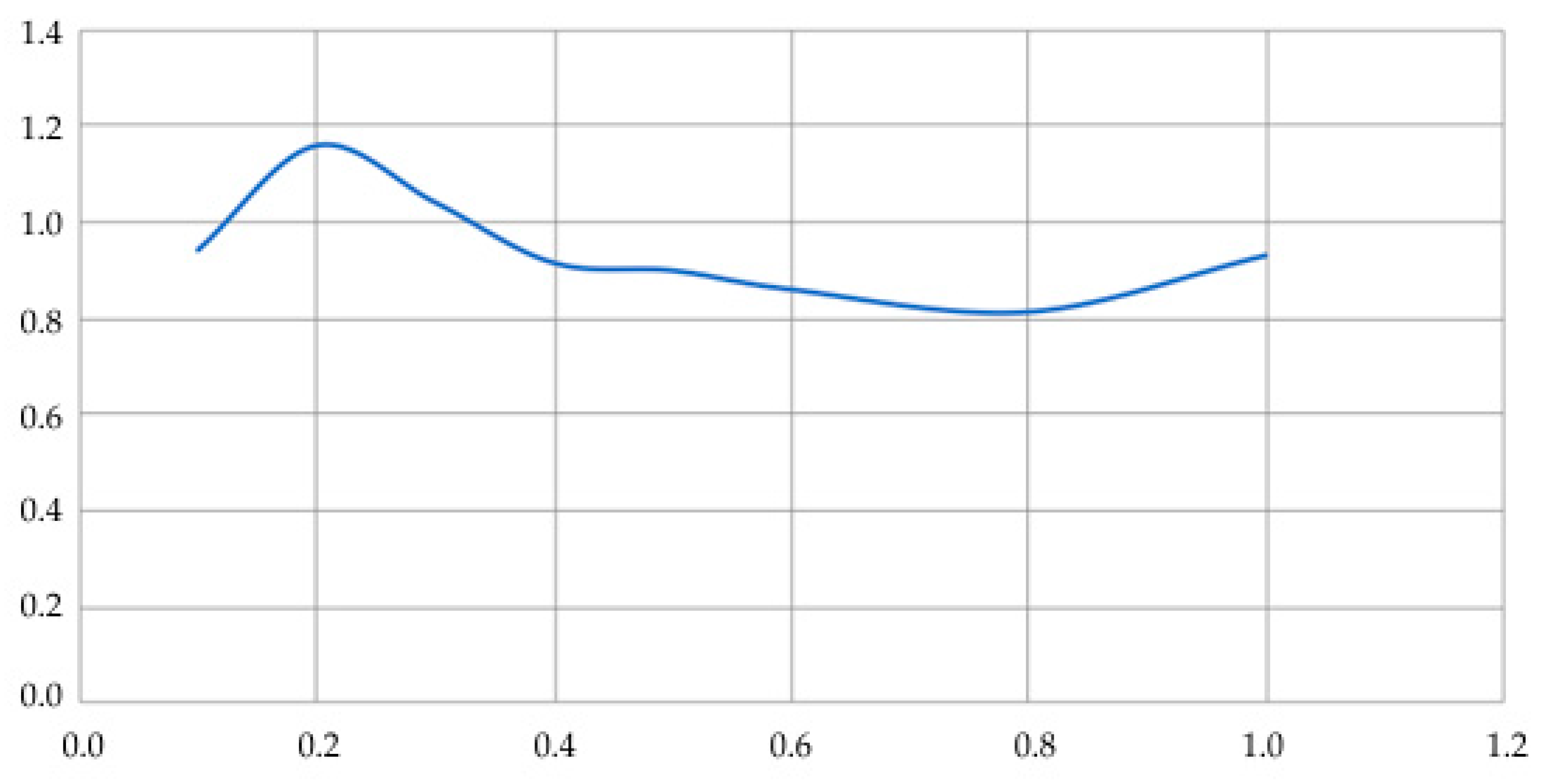
Figure 8 shows the dependence of the characteristic function on the thickness of the surface layer. Asphalt concrete with a modulus of elasticity
E4 = 1600 MPa was taken as a layer material.
Figure 8 shows that for the accepted value of the modulus of elasticity
E4 = 1600 MPa in a wide range of layer thickness
D4; the characteristic function is in the range from 0.8 to 1.2, which makes it possible to effectively apply dependence (25) in practical measurements of the stress–strain state.
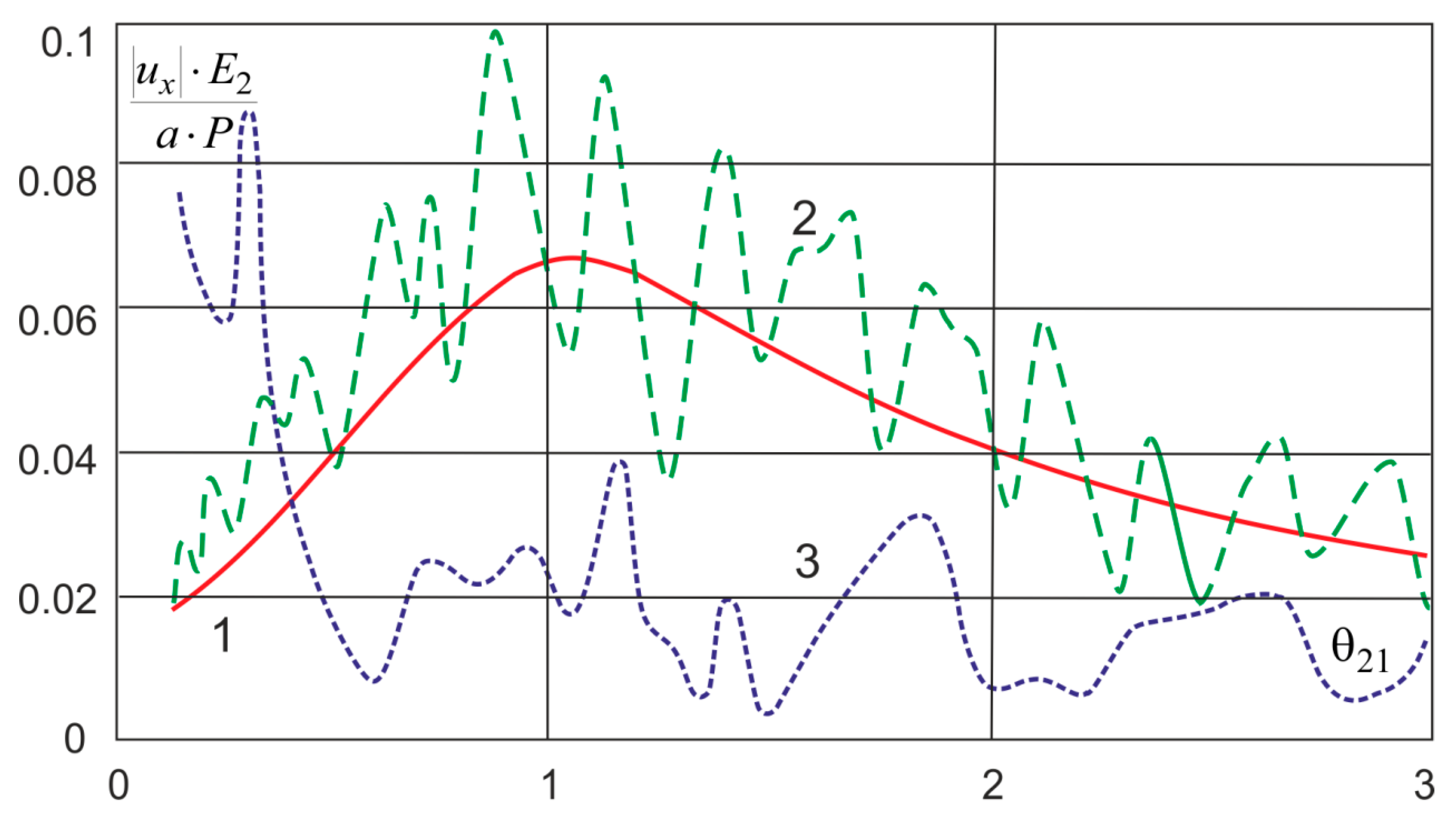
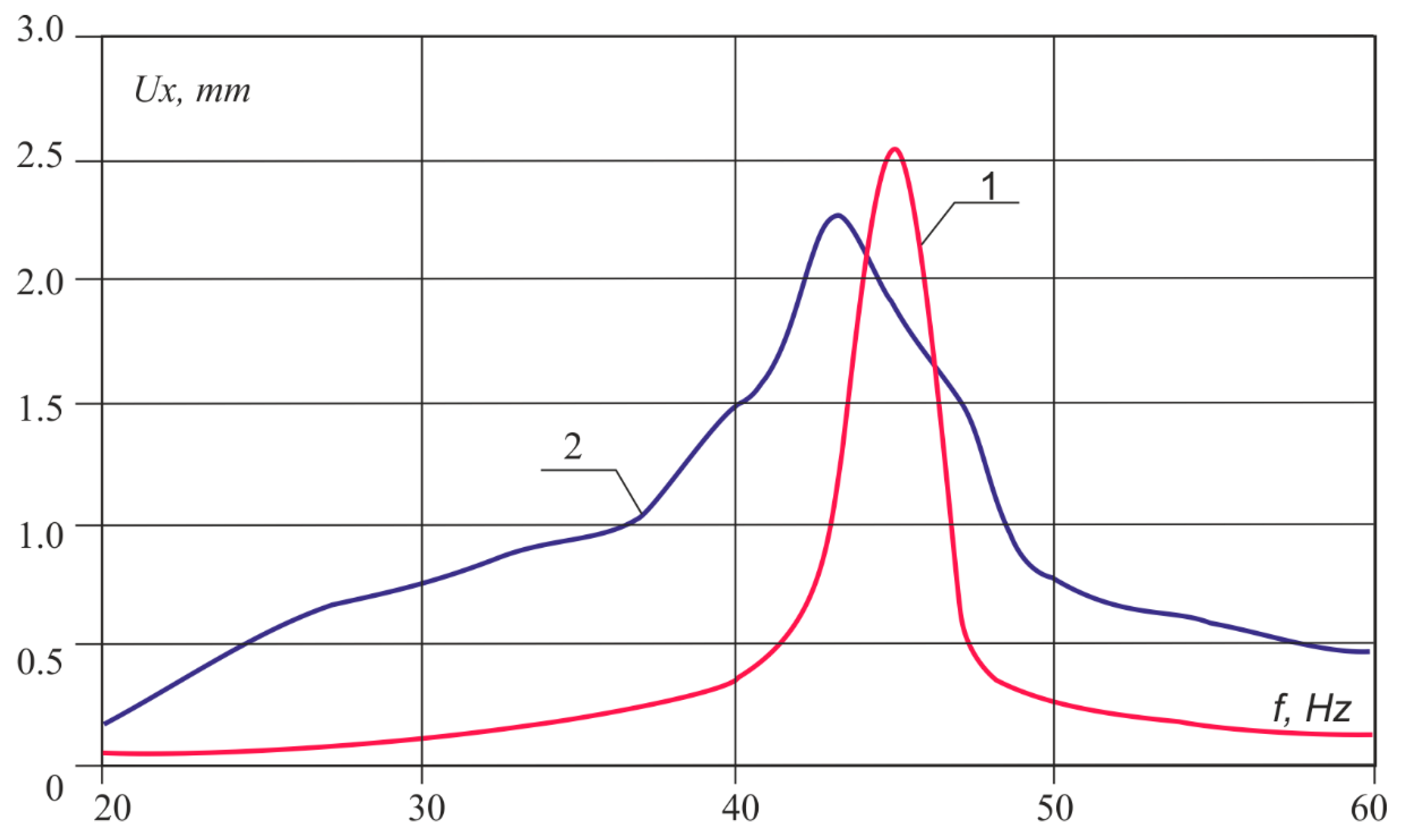
Figure 9 shows the dependences of the amplitude–frequency characteristics of the layered medium. Here, 1 is a half-space; 2 is a softer near-surface layer
E4 <
E3; and 3 is a harder near-surface layer
E4 >
E3.
P is the load,
a is the coordinate of the point of deepening of the object, and
E2 is the elastic modulus of the half-space. The dependence is plotted in dimensionless quantities.
Figure 9 shows that the softer near-surface layer
E4 <
E3 resonates and, due to multiple reflections from the layer boundaries, gives a change in the vibration amplitude. This effect differs from the results obtained by Pryakhina et al. [
33], since, in our case, a massive object differs from a solid inclusion. A tougher layer works differently. Only in the low-frequency region there are still resonance frequencies corresponding to bending vibrations; in the rest of the range, resonances are damped by the upper hard layer. The results obtained are in good agreement with those of Zhou et al. [
24], who obtained a solution for a cylindrical region in a layered medium.
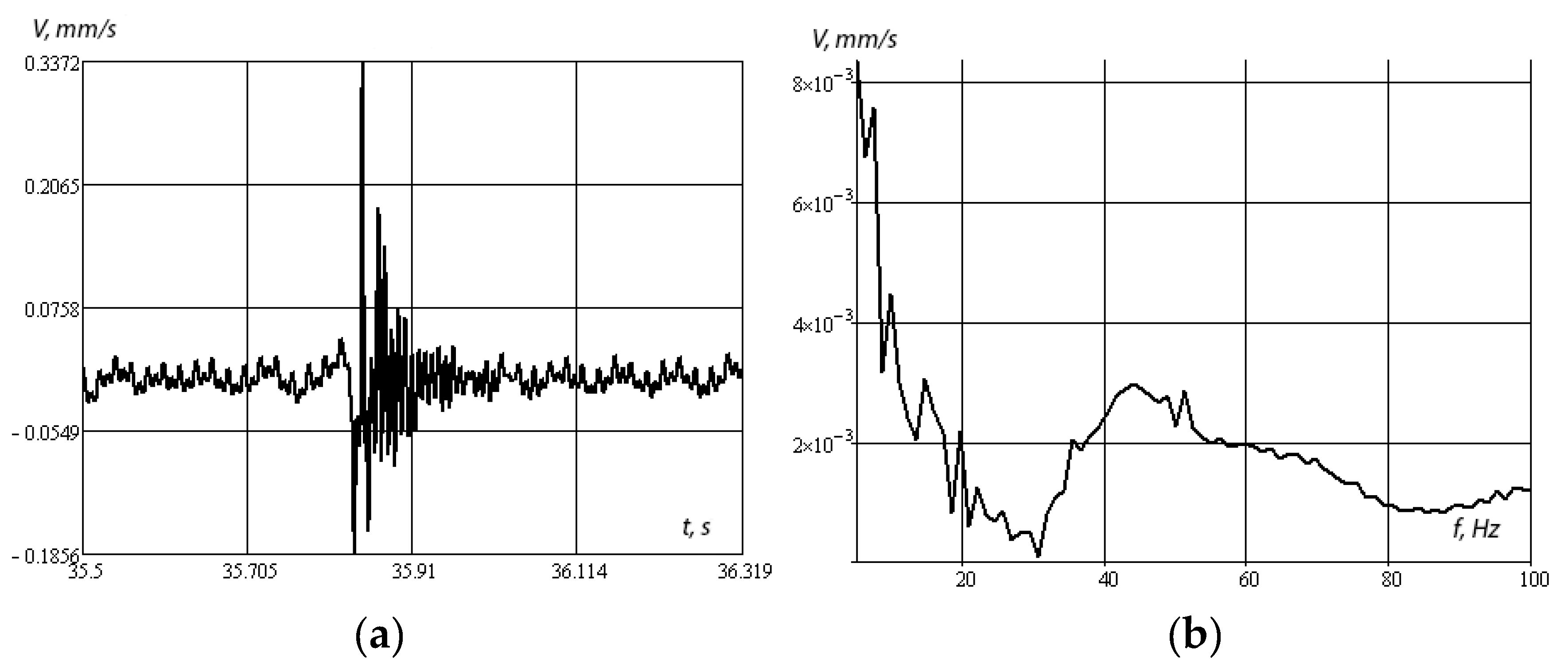
Figure 10a,b shows the amplitude–time and amplitude–frequency dependences under shock loading.
Figure 10b shows that, under shock loading, the most energetic resonances lie in the low-frequency region and in the region of about 43 Hz, and then the frequency response fades. Note that the presence of low-frequency maxima of the amplitude–frequency characteristic is explained by the presence of a massive object immersed in a layered medium as a whole. In the case of significant rigidity of the underlying half-space, such maxima can be significant. In the limiting case of a rigidly clamped layer, the presence of isolated low-frequency resonances for a surface object was considered in the works of I.I. Vorovich [
34,
35].
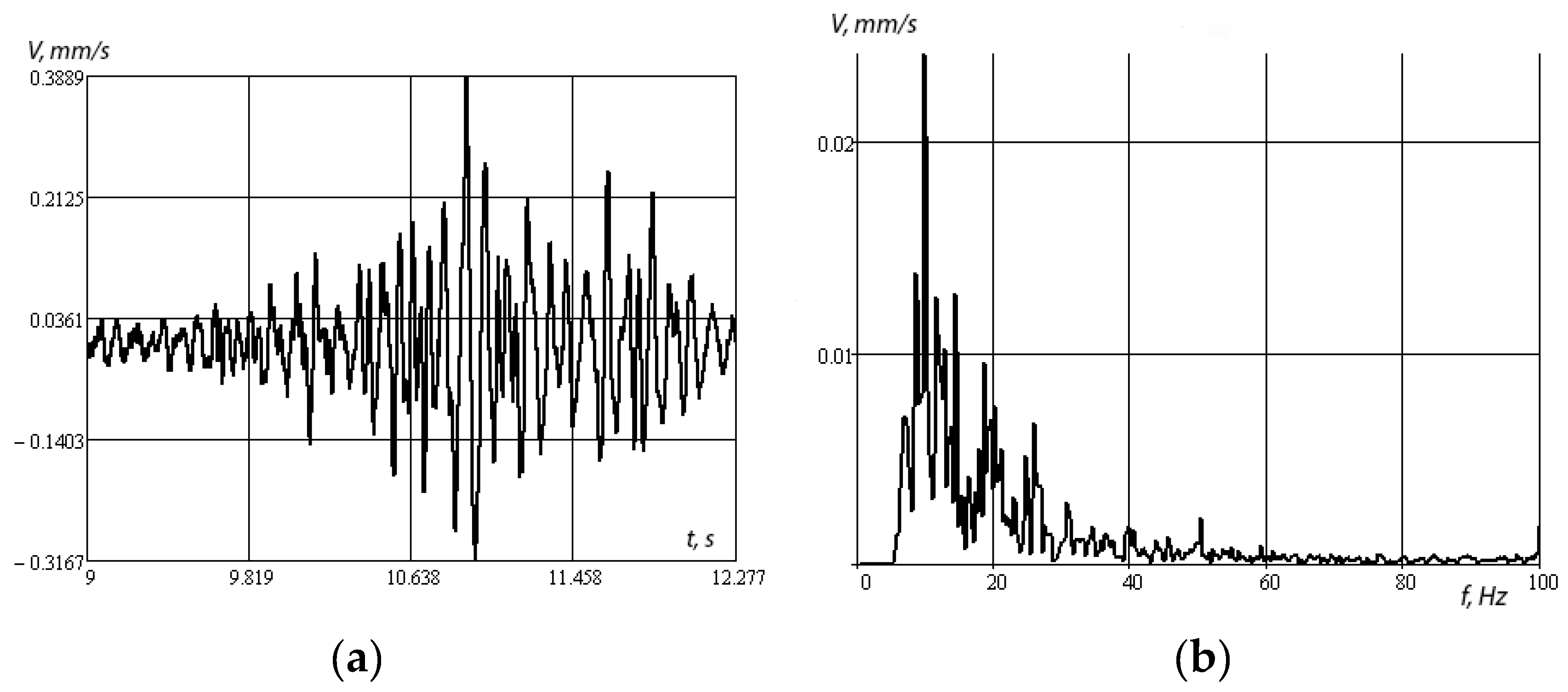
Figure 11a,b shows the amplitude–time and amplitude–frequency dependences when a KamAZ car is driven at a speed of 50 km/h.
Figure 11 shows that the energy resonances lie in the low-frequency region. Resonance frequencies at 10, 17, and 19 Hz are due to the frequency of external influences when driving a car. Accordingly, the response of the structure changes its vibration spectrum.
Figure 12 shows an example of calculating the overlap spectrum using the amplitude–frequency characteristic of the vibration velocities of the overlap under impact and the Gaussian pulse spectrum. The figure clearly shows a peak around 42 Hz. It should be noted that, when passing vehicles on the amplitude–frequency characteristics, resonance peaks were not observed at frequencies above 20 Hz. It follows from this that the frequency range of the impact of vehicles lies below the natural frequencies of bending vibrations of floors.
5. Conclusions
The article discusses the problem and proposes a method for monitoring underground structures of arbitrary shape, lying in layered media, under various external dynamic influences. An analytical solution to the problem of the dynamics of layered media with buried objects of arbitrary shape is obtained. On the example of an underground passage, a practical example of the estimation of resonance frequencies and characteristic function for various characteristics and geometry of layers, is considered.
The instrumental analysis of the stress–strain state is complicated by the fact that at the characteristic function, which depends on the properties of the medium and has a nonlinear character. The frequency ranges in which the characteristic function is close to 1 are identified and recommendations are given for processing sensor signals for buried objects.
It is shown that the softer near-surface layer E4 < E3 resonates and, due to multiple reflections from the layer boundaries, gives a change in the vibration amplitude. A tougher layer works differently. Only in the low-frequency region there are still resonance frequencies corresponding to bending vibrations; in the rest of the range, resonances are damped by the upper hard layer.
As part of the research methodology development, it is proposed to use it in solving of inverse structural mechanics problems for reconstruction of buried object properties by measuring and analyzing vibration responses on a medium surface and an internal object geometry, as well as in the development of linear consolidation theory methods for layered water-saturated soils.


