Direct Georeferencing for the Images in an Airborne LiDAR System by Automatic Boresight Misalignments Calibration


Abstract
1. Introduction
2. Materials and Methods
2.1. Sample Materials
2.2. Methods
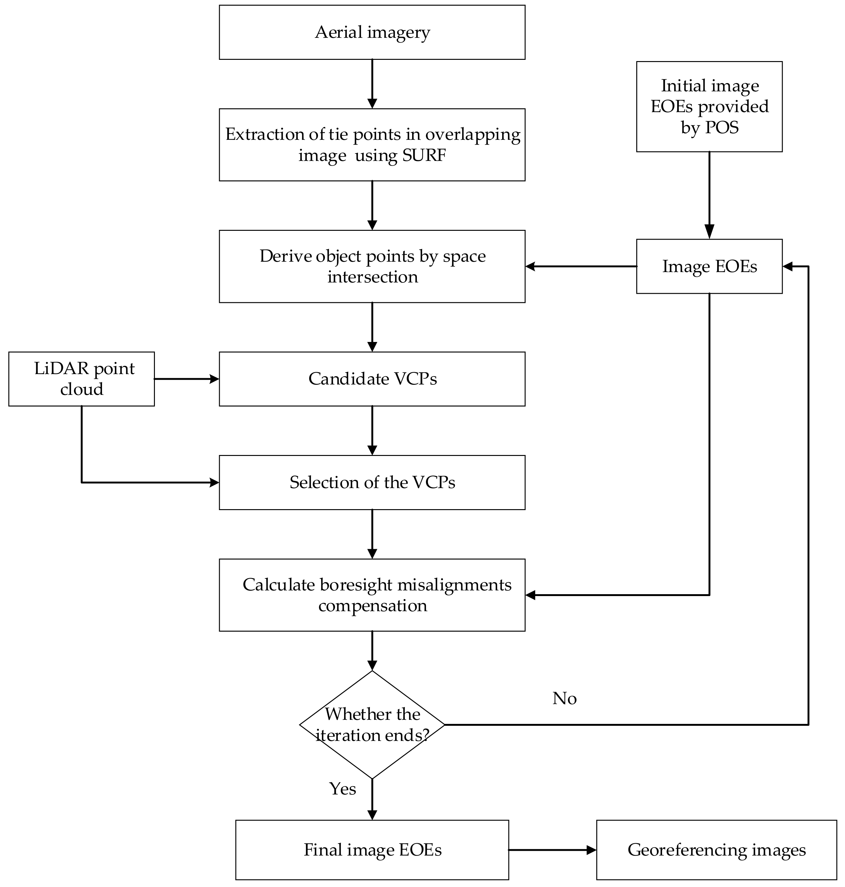
2.2.1. Overview of the Methods
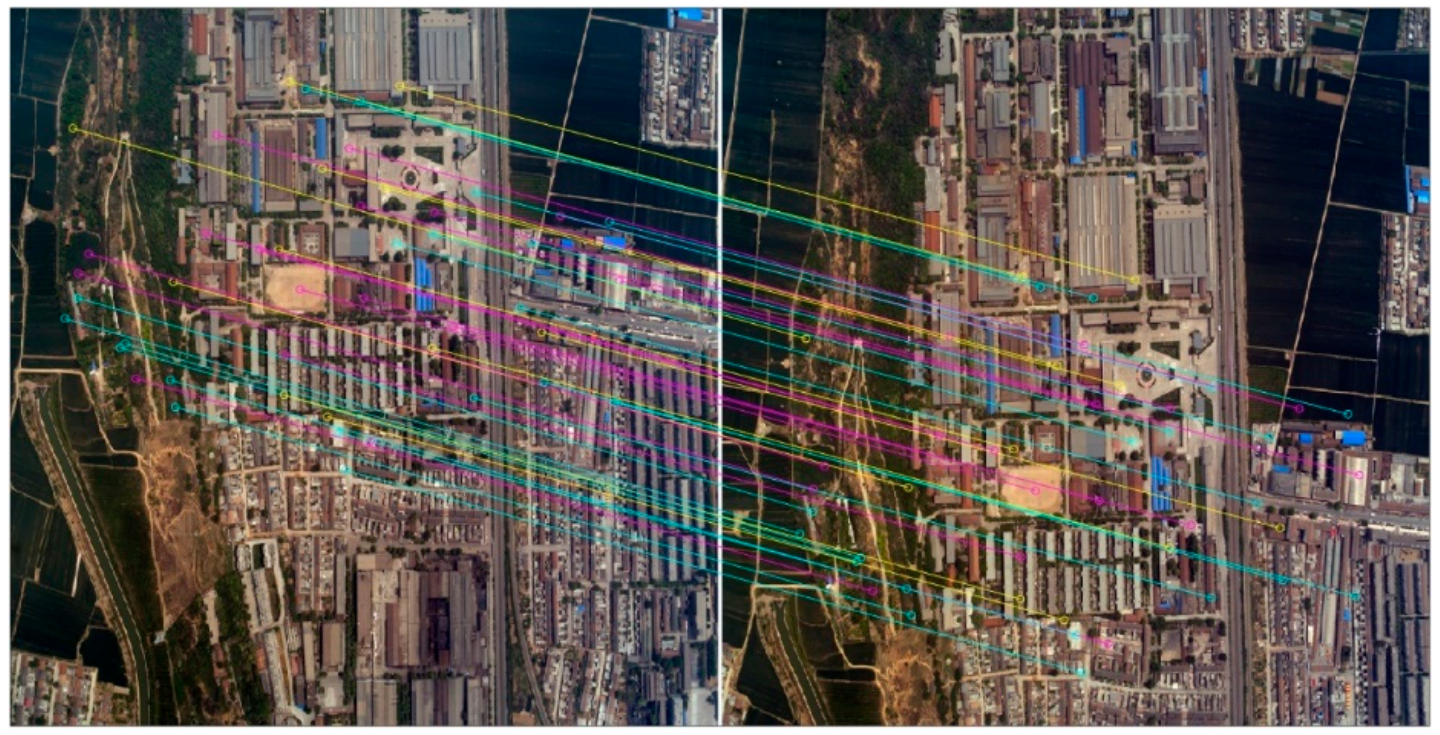
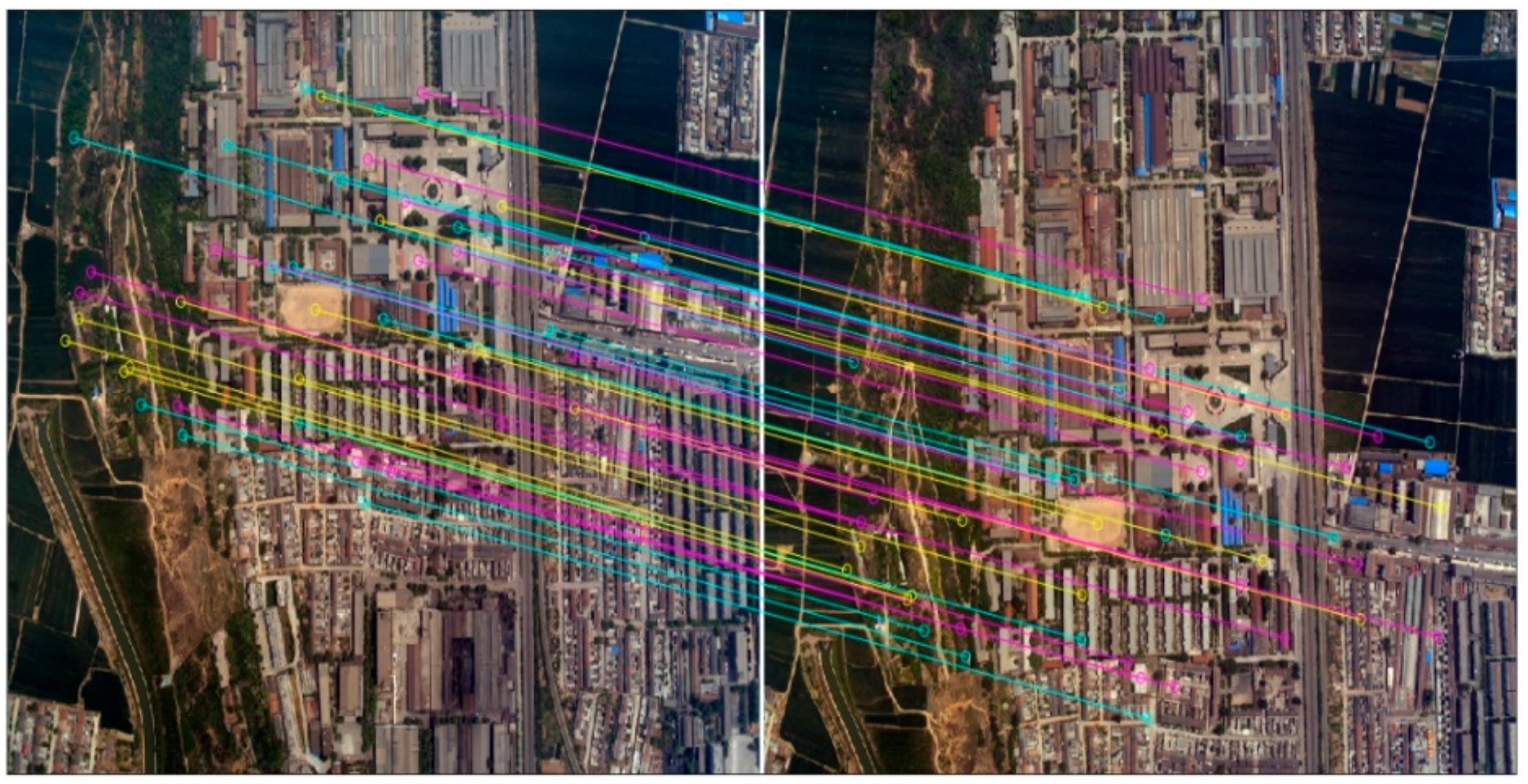
- Select sub-block images collected over a relatively flat area from image set and extract tie points in the overlapping areas of the sub-block images using a Speed-Up Robust Features (SURF) algorithm [49].
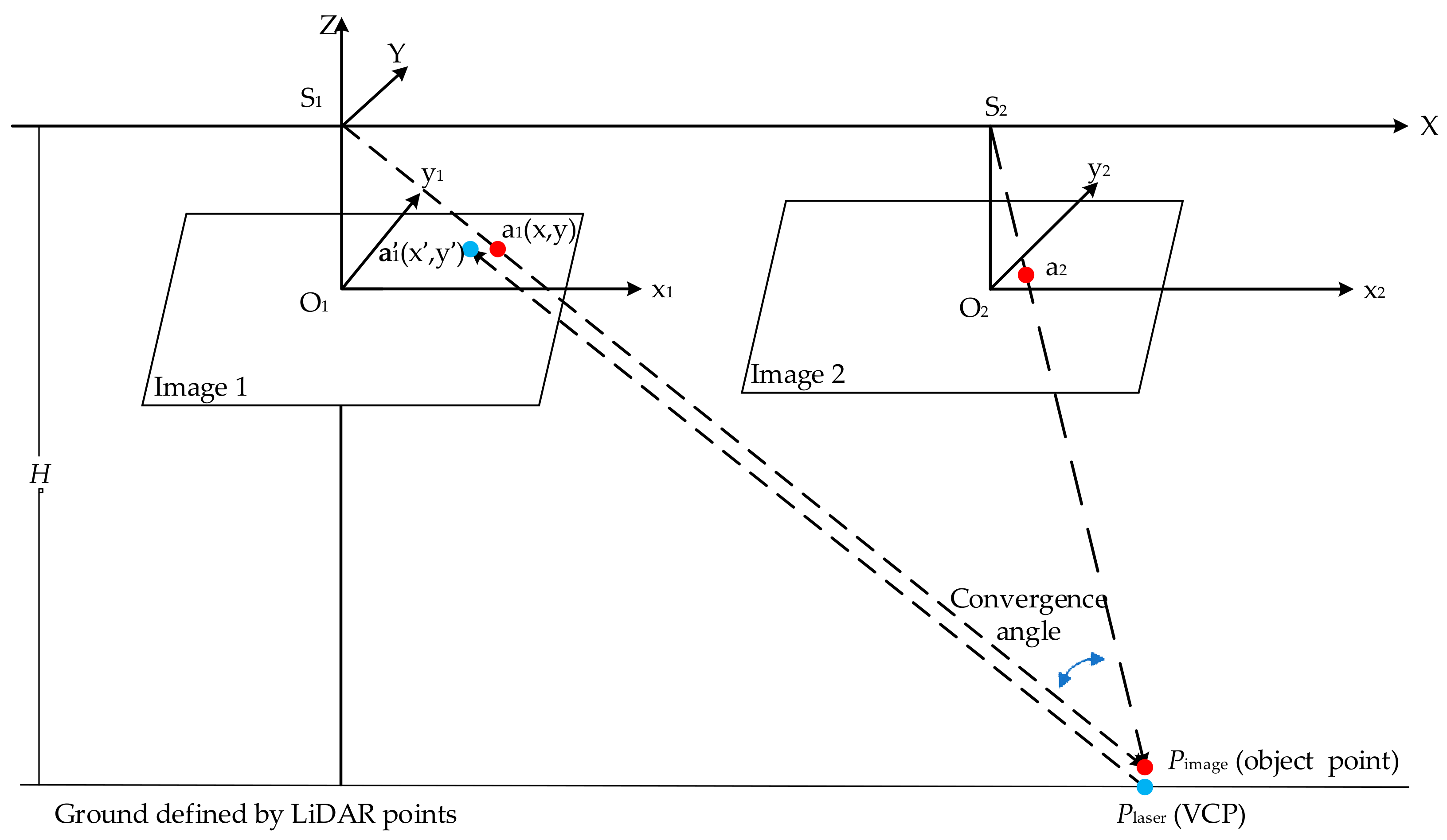
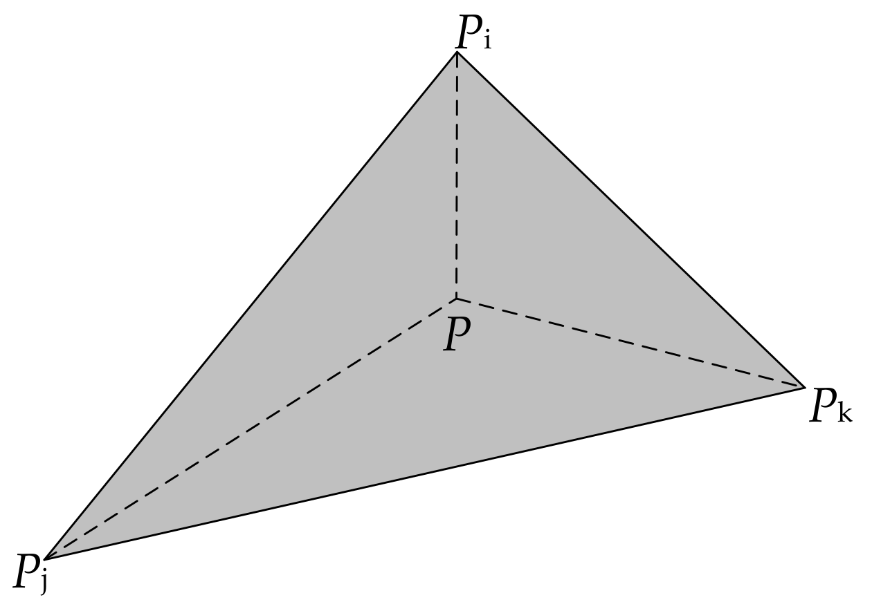
- For each pair of tie points, the object point can be derived by space intersection.
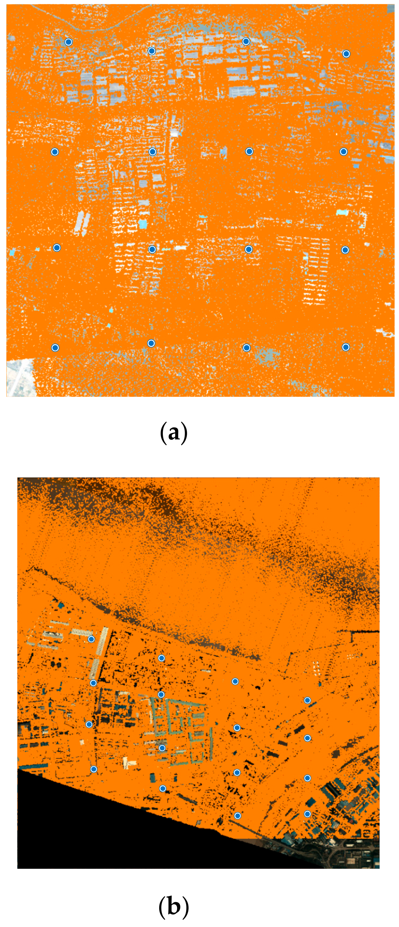
- Replace the elevation values of object points by those derived from LiDAR point cloud. These new points are called VCPs.
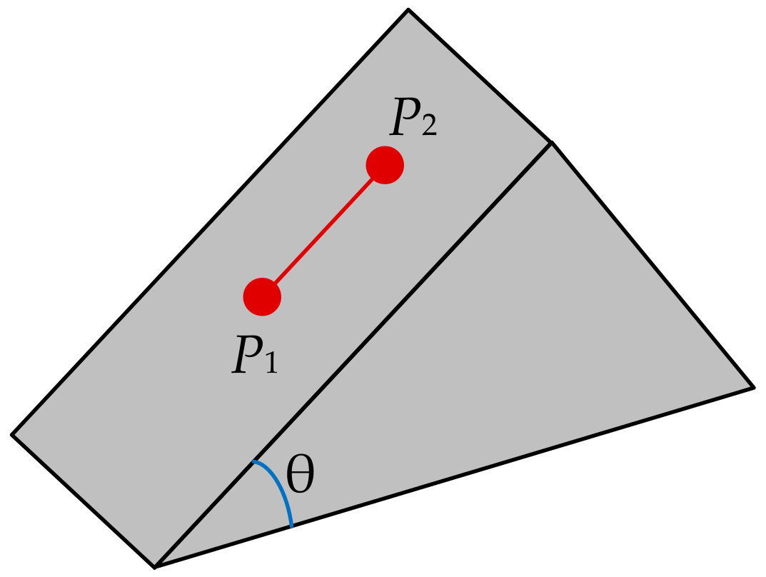
- An automatic VCP selection procedure is designed to perform various assessments to guarantee high quality VCPs can be selected.
- Adjustment equation is established to perform boresight misalignments compensation based on the combination of the VCP set and collinearity equations.
- Repeat Steps 2–5 until the total distance between all tie points and their corresponding points that are derived from VCPs remains stable in the iteration or the maximum iteration has been reached.
2.2.2. Detection and Matching of Tie Points in Overlapping Images Using SURF Algorithm
2.2.3. Selection of the VCPs
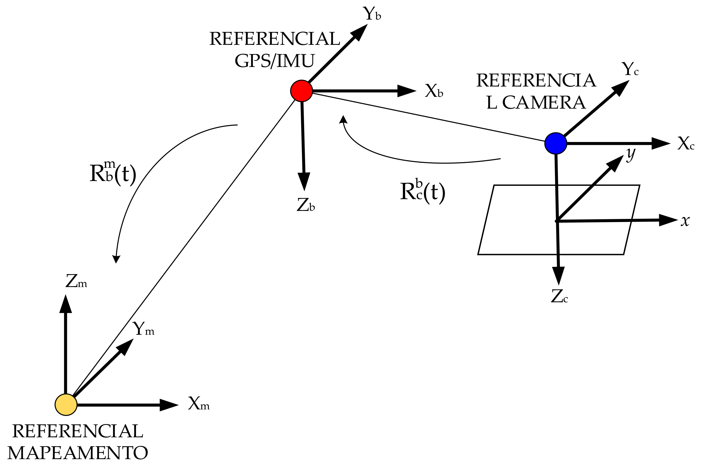
2.2.4. Boresight Misalignments Calibration
3. Results
3.1. Results of Tie Points Detection and Matching
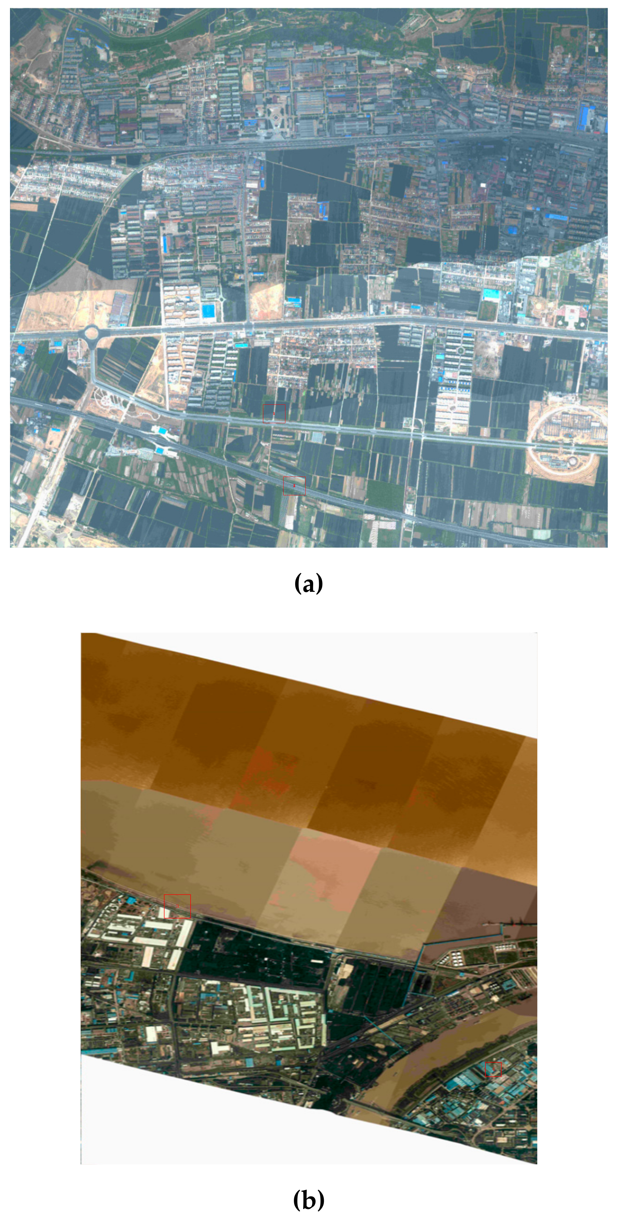
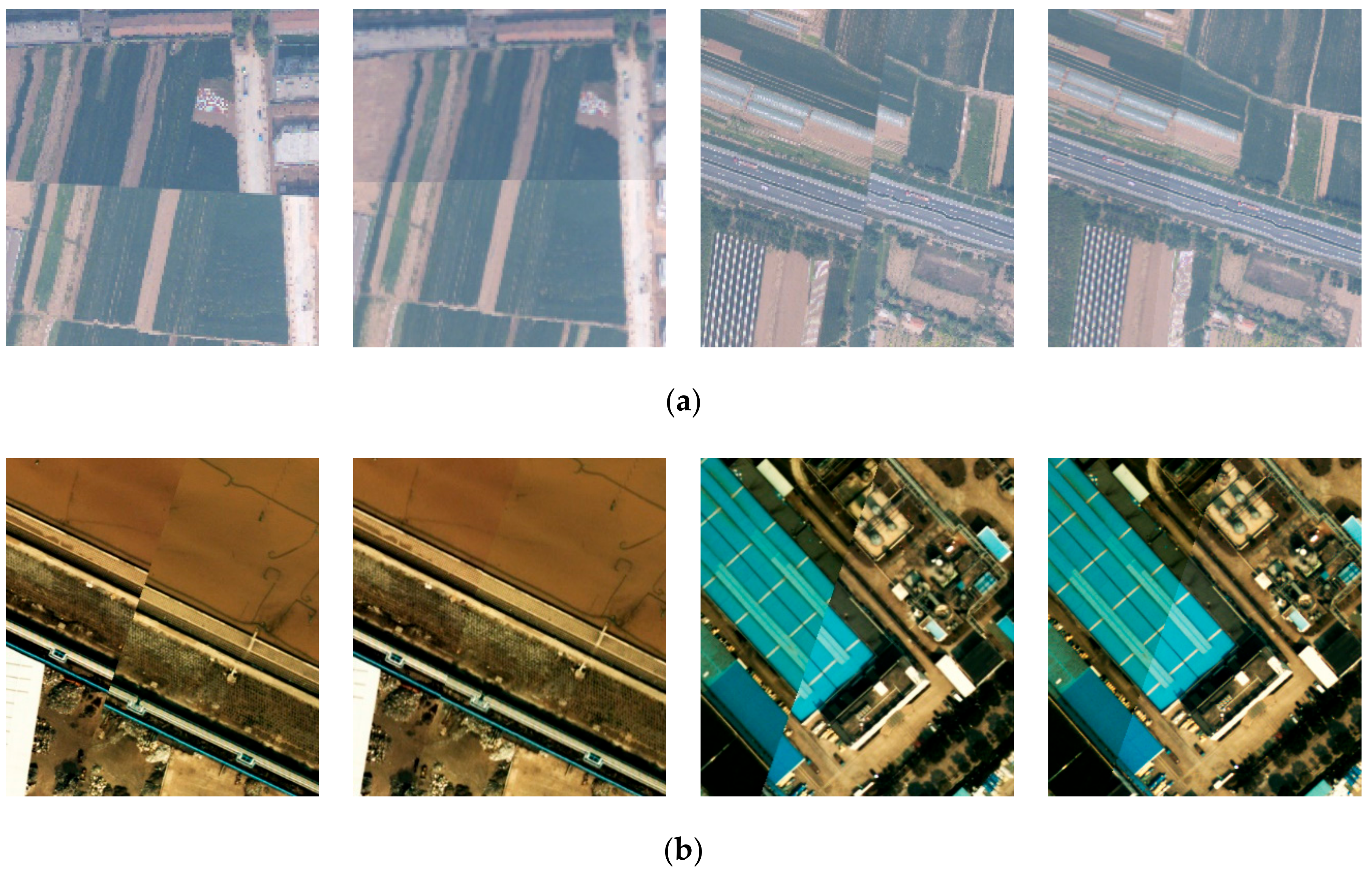
3.2. Results of Direct Georeferencing by Boresight Misalignments Calibration
4. Discussions
5. Conclusions
Author Contributions
Funding
Conflicts of Interest
References
- Kobler, A.; Pfeifer, N.; Ogrinc, P.; Todorovski, L.; Oštir, K.; Džeroski, S. Repetitive interpolation: A robust algorithm for DTM generation from Aerial Laser Scanner Data in forested terrain. Remote. Sens. Environ. 2007, 108, 9–23. [Google Scholar] [CrossRef]
- Polat, N.; Uysal, M.M. Investigating performance of Airborne LiDAR data filtering algorithms for DTM generation. Measurement 2015, 63, 61–68. [Google Scholar] [CrossRef]
- Ma, H.; Zhou, W.; Zhang, L.; Wang, S. Decomposition of small-footprint full waveform LiDAR data based on generalized Gaussian model and grouping LM optimization. Meas. Sci. Technol. 2017, 28, 045203. [Google Scholar] [CrossRef]
- Meng, X.; Wang, L.; Currit, N. Morphology-based Building Detection from Airborne Lidar Data. Photogramm. Eng. Remote Sens. 2009, 75, 437–442. [Google Scholar] [CrossRef]
- Hamraz, H.; Jacobs, N.; Contreras, M.A.; Clark, C.H. Deep learning for conifer/deciduous classification of airborne LiDAR 3D point clouds representing individual trees. ISPRS J. Photogramm. Remote Sens. 2019, 158, 219–230. [Google Scholar] [CrossRef]
- Axelsson, P. DEM generation from laser scanner data using adaptive TIN models. Int. Arch. Photogram. Remote Sens. 2000, 33, 110–118. [Google Scholar]
- Mitishita, E.; Cortes, J.; Centeno, J.A.S. Indirect georeferencing of digital SLR imagery using signalised lidar control points. Photogramm. Rec. 2011, 26, 58–72. [Google Scholar] [CrossRef]
- Huang, Y.; Zhuo, L.; Tao, H.; Shi, Q.; Liu, K. A Novel Building Type Classification Scheme Based on Integrated LiDAR and High-Resolution Images. Remote Sens. 2017, 9, 679. [Google Scholar] [CrossRef]
- Castagno, J.; Atkins, E.M. Roof Shape Classification from LiDAR and Satellite Image Data Fusion Using Supervised Learning. Sensors 2018, 18, 3960. [Google Scholar] [CrossRef]
- Luo, S.; Wang, C.; Xi, X.; Zeng, H.; Li, D.; Xia, S.; Wang, P. Fusion of Airborne Discrete-Return LiDAR and Hyperspectral Data for Land Cover Classification. Remote Sens. 2015, 8, 3. [Google Scholar] [CrossRef]
- Xu, Z.; Guan, K.; Casler, N.; Peng, B.; Wang, S. A 3D convolutional neural network method for land cover classification using LiDAR and multi-temporal Landsat imagery. ISPRS J. Photogramm. Remote Sens. 2018, 144, 423–434. [Google Scholar] [CrossRef]
- Han, X.; Wang, H.; Lu, J.; Zhao, C. Road detection based on the fusion of Lidar and image data. Int. J. Adv. Robot. Syst. 2017, 14, 1–10. [Google Scholar] [CrossRef]
- Sameen, M.; Pradhan, B. A Two-Stage Optimization Strategy for Fuzzy Object-Based Analysis Using Airborne LiDAR and High-Resolution Orthophotos for Urban Road Extraction. J. Sens. 2017, 2017, 1–17. [Google Scholar] [CrossRef]
- Matsuki, T.; Yokoya, N.; Iwasaki, A. Hyperspectral Tree Species Classification of Japanese Complex Mixed Forest With the Aid of Lidar Data. IEEE J. Sel. Top. Appl. Earth Obs. Remote Sens. 2015, 8, 2177–2187. [Google Scholar] [CrossRef]
- Pham, L.; Brabyn, L.; Ashraf, S. Combining QuickBird, LiDAR, and GIS topography indices to identify a single native tree species in a complex landscape using an object-based classification approach. Int. J. Appl. Earth Obs. Geoinf. 2016, 50, 187–197. [Google Scholar] [CrossRef]
- Gneeniss, A.; Mills, J.P.; Miller, P.E. In-flight photogrammetric camera calibration and validation via complementary lidar. ISPRS J. Photogramm. Remote Sens. 2015, 100, 3–13. [Google Scholar] [CrossRef]
- Grussenmeyer, P.; Al Khalil, O. Solutions for Exterior Orientation in Photogrammetry: A Review. Photogramm. Rec. 2002, 17, 615–634. [Google Scholar] [CrossRef]
- Mikolajczyk, K.; Schmid, C. Indexing Based on Scale Invariant Interest Points. In Proceedings of the Eighth IEEE International Conference on Computer Vision ICCV, Vancouver, BC, Canada, 7–14 July 2001; Volume 1, pp. 525–531. [Google Scholar] [CrossRef]
- Honkavaara, E.; Markelin, L.; Ahokas, E.; Kuittinen, R.; Peltoniemi, J. Calibrating digital photogrammetric airborne imaging systems in a test field. Int. Arch. Photogramm. Remote Sens. Spat. Inf. Sci. 2008, 37, 555–560. [Google Scholar]
- Yastikli, N.; Jacobsen, K. Direct Sensor Orientation for Large Scale Mapping—Potential, Problems, Solutions. Photogramm. Rec. 2005, 20, 274–284. [Google Scholar] [CrossRef]
- Gautam, D.; Lucieer, A.; Watson, C.; McCoull, C. Lever-arm and boresight correction, and field of view determination of a spectroradiometer mounted on an unmanned aircraft system. ISPRS J. Photogramm. Remote Sens. 2019, 155, 25–36. [Google Scholar] [CrossRef]
- Seo, J.; Lee, H.K.; Jee, G.; Park, C.G. Lever arm compensation for GPS/INS/Odometer integrated system. Int. J. Control Autom. Syst. 2006, 4, 247–254. [Google Scholar]
- Heier, H.; Kiefner, M.; Zeitler, W. Calibration of the Digital Modular Camera. In Proceedings of the FIG XXII International Congress, Washington, DC, USA, 19–26 April 2002; p. 11. [Google Scholar]
- Skaloud, J.; Cramer, M.; Schwarz, K.P. Exterior orientation by direct measurement of position and attitude. Bmc Health Serv. Res. 1996, 8, 789. [Google Scholar]
- Skaloud, J. Optimizing Georeferencing of Airborne Survey Systems by INS/GPS. Ph.D. Thesis, Department of Geomatics Engineering, The University of Calgary, Calgary, Alberta, 1999. [Google Scholar]
- Heipke, C.; Jacobsen, K.; Wegmann, H. The OEEPE Test on Integrated Sensor Orientation—Results of Phase I. In Proceedings of the Photogrammetric Week, Stuttgart, Germany, 24-28 September 2001; Fritsch, D., Spiller, R., Eds.; Wichmann Verlag: Berlin, Germany, 2001; pp. 195–204. [Google Scholar]
- Jacobsen, K. Aspects of Handling Image Orientation by Direct Sensor Orientation. In Proceedings of the American Society of Photogrammetry and Remote Sensing Annual Convention, St. Louis, MO, USA, 23–27 April 2001; pp. 629–633. [Google Scholar]
- Mostafa, M.M.R.; Corporation, A. Camera/IMU Boresight Calibration: New Advances and Performance Analysis. In Proceedings of the American Society of Photogrammetry and Remote Sensing Annual Conference, Washington, DC, USA, 21–26 April 2002; p. 12. [Google Scholar]
- Honkavaara, E. Calibration field structures for GPS/IMU/camera-system calibration. Photogramm. J. Finl. 2003, 18, 3–15. [Google Scholar]
- Honkavaara, E. Calibration in direct georeferencing: Theoretical considerations and practical results. Photogramm. Eng. Remote Sens. 2004, 70, 1207–1208. [Google Scholar]
- Jacobsen, K. Direct integrated sensor orientation—Pros and Cons. Int. Arch. Photogramm. Remote Sens. 2004, 35, 829–835. [Google Scholar]
- Filho, L.E.; Mitishita, E.A.; Kersting, A.P.B. Geometric Calibration of an Aerial Multihead Camera System for Direct Georeferencing Applications. IEEE J. Sel. Top. Appl. Earth Obs. Remote Sens. 2017, 10, 1–12. [Google Scholar] [CrossRef]
- Kruck, E.J. Simultaneous calibration of digital aerial survey cameras. In Proceedings of the EuroSDR Commission I and ISPRS Working Group 1/3 Workshop EuroCOW, Castelldefels, Spain, 25–27 January 2006; p. 7. [Google Scholar]
- Jacobsen, K. Geometric handling of large size digital airborne frame camera images. Opt. 3D Meas. Tech. 2007, 8, 164–171. [Google Scholar]
- Delara, R.; Mitishita, E.; Habib, A. Bundle adjustment of images from nonmetric CCD camera using LiDAR data as control points. Int. Arch. Photogramm. Remote Sens. Spat. Inf. Sci. 2004, 20, 13–18. [Google Scholar]
- Habib, A.; Ghanma, M.; Mitishita, E.; Kim, E.; Kim, C.J. Image georeferencing using LIDAR data. In Proceedings of the 2005 IEEE International Geoscience and Remote Sensing Symposium, 2005. IGARSS ’05, Seoul, Korea, 29 July 2005; Volume 2, pp. 1158–1161. [Google Scholar] [CrossRef]
- Habib, A.; Ghanma, M.; Morgan, M.; Al-Ruzouq, R. Photogrammetric and Lidar Data Registration Using Linear Features. Photogramm. Eng. Remote. Sens. 2005, 71, 699–707. [Google Scholar] [CrossRef]
- Kwak, T.-S.; Kim, Y.-I.; Yu, K.-Y.; Lee, B.K. Registration of aerial imagery and aerial LiDAR data using centroids of plane roof surfaces as control information. KSCE J. Civ. Eng. 2006, 10, 365–370. [Google Scholar] [CrossRef]
- Liu, X.; Zhang, Z.; Peterson, J.; Chandra, S. Lidar-derived high quality ground control information and DEM for image orthorectification. GeoInformatica 2007, 11, 37–53. [Google Scholar] [CrossRef]
- Yastikli, N.; Toth, C.; Brzezinska, D. In-Situ camera and boresight calibration with lidar data. In Proceedings of the 5th International Symposium on Mobile Mapping Technology, Padua, Itália, 29–31 May 2007; p. 6. [Google Scholar]
- Mitishita, E.; Habib, A.F.; Centeno, J.A.S.; Machado, A.M.L.; Lay, J.C.; Wong, C. Photogrammetric and lidar data integration using the centroid of a rectangular roof as a control point. Photogramm. Rec. 2008, 23, 19–35. [Google Scholar] [CrossRef]
- Ding, M.; Lyngbaek, K.; Zakhor, A. Automatic registration of aerial imagery with untextured 3D LiDAR models. In Proceedings of the 2008 IEEE Conference on Computer Vision and Pattern Recognition, Anchorage, AK, USA, 24–26 January 2008; pp. 23–28. [Google Scholar] [CrossRef]
- Wang, L.; Neumann, U. A Robust Approach for Automatic Registration of Aerial Images with Untextured Aerial LiDAR Data. In Proceedings of the 2009 IEEE Computer Society Conference on Computer Vision and Pattern Recognition, Miami, FL, USA, 20–25 June 2009; pp. 2623–2630. [Google Scholar] [CrossRef]
- Wildan, F.; Aldino, R.; Aji, P.P. Application of LIDAR Technology for GCP Determination in Papua Topographic Mapping Scale 1:50,000. In Proceedings of the 10th Annual Asian Conference & Exhibition on Geospatial Information, Technology & Applications, Jakarta, Indonesia, 17–19 October 2011; p. 13. [Google Scholar]
- Siying, C.; Hongchao, M.; Yinchao, Z.; Liang, Z.; Jixian, X.; He, C. Boresight Calibration of Airborne LiDAR System Without Ground Control Points. IEEE Geosci. Remote Sens. Lett. 2011, 9, 85–89. [Google Scholar] [CrossRef]
- Gneeniss, A.S. Integration of LiDAR and Photogrammetric Data for Enhanced Aerial Triangulation and Camera Calibration. Ph.D. Thesis, Newcastle University, Newcastle upon Tyne, UK, 2014. [Google Scholar]
- Rusu, R.B.; Cousins, S. 3D Is here: Point Cloud Library (PCL). In Proceedings of the 2011 IEEE International Conference on Robotics and Automation, Shanghai, China, 9–13 May 2011; pp. 1–4. [Google Scholar] [CrossRef]
- Dharmapuri, S.S. Vertical accuracy validation of LiDAR data. LiDAR Mag. 2014, 4, 1. [Google Scholar]
- Bay, H.; Ess, A.; Tuytelaars, T.; Van Gool, L. Speeded-Up Robust Features (SURF). Comput. Vis. Image Underst. 2008, 110, 346–359. [Google Scholar] [CrossRef]
- Goshtasby, A.; Stockman, G.; Page, C. A Region-Based Approach to Digital Image Registration with Subpixel Accuracy. IEEE Trans. Geosci. Remote Sens. 1986, 24, 390–399. [Google Scholar] [CrossRef]
- You, J.; Bhattacharya, P. A wavelet-based coarse-to-fine image matching scheme in a parallel virtual machine environment. IEEE Trans. Image Process. 2000, 9, 1547–1559. [Google Scholar] [CrossRef]
- Lowe, D.G. Distinctive Image Features from Scale-Invariant Keypoints. Int. J. Comput. Vis. 2004, 60, 91–110. [Google Scholar] [CrossRef]
- Gonçalves, H.; Corte-Real, L.; Gonçalves, J.A. Automatic Image Registration Through Image Segmentation and SIFT. IEEE Trans. Geosci. Remote Sens. 2011, 49, 2589–2600. [Google Scholar] [CrossRef]
- Ye, F.; Su, Y.; Xiao, H.; Zhao, X.; Min, W. Remote Sensing Image Registration Using Convolutional Neural Network Features. IEEE Geosci. Remote. Sens. Lett. 2018, 15, 232–236. [Google Scholar] [CrossRef]
- Jeong, J. Imaging Geometry and Positioning Accuracy of Dual Satellite Stereo Images: A Review. ISPRS Ann. Photogramm. Remote Sens. Spat. Inf. Sci. 2017, 4, 235–242. [Google Scholar] [CrossRef]
- Kodors, S.; Kangro, I. Simple method of LiDAR point density definition for automatic building recognition. Eng. Rural Dev. 2016, 5, 415–424. [Google Scholar]
- Jacobsen, K. BLUH Bundle Block Adjustment; Program User Manual; Institute of Photogrammetry and GeoInformation, Leibniz University Hannover: Hannover, Germany, 2008; p. 34. [Google Scholar]
- Baumker, M.; Heimes, F.J. New Calibration and Computing Method for Direct Georeferencing of Image and Scanner Data Using the Position and Angular Data of an Hybrid Inertial Navigation System. Integr. Sens. Orientat. 2002, 43, 197–212. [Google Scholar]
- Zhao, H.; Zhang, B.; Wu, C.; Zuo, Z.; Chen, Z. Development of a Coordinate Transformation method for direct georeferencing in map projection frames. ISPRS J. Photogramm. Remote Sens. 2013, 77, 94–103. [Google Scholar] [CrossRef]
- Mistry, D.; Banerjee, A. Comparison of Feature Detection and Matching Approaches: SIFT and SURF. GRD J. Global Res. Dev. J. Eng. 2017, 2, 7–13. [Google Scholar]


| Flight Information | Target Area | Max Flight Height | Min Flight Height | Number of Flights | Number of Images |
| Xi’an, China | 1450 m | 1387 m | 4 | 49 | |
| LiDAR Points | Sensor | Point Cloud Density | FOV | Size of Area | Average Overlap |
| Leica ALS60 | 1.9/m2 | 45° | 11 km2 | 48% | |
| Aerial Images | Type of Camera | Pixel Size | Focal Length | Forward Overlap | Side Overlap |
| RCD105 | 0.0068 mm | 60 mm | 70% | 45% |
| Flight Information | Target Area | Max Flight Height | Min Flight Height | Number of Flights | Number of Images |
| Ningbo, China | 2397 m | 2304 m | 3 | 27 | |
| LiDAR Points | Sensor | Point Cloud Density | FOV | Size of Area | Average Overlap |
| Leica ALS70 | 0.60/m2 | 45° | 15 km2 | 20% | |
| Aerial Images | Type of Camera | Pixel Size | Focal Length | Forward Overlap | Side Overlap |
| RCD30 | 0.006 mm | 53 mm | 60% | 30% |
| Algorithm | Tie Points Offset | Time Cost | Number of Tie Points | Correct Tie Points | Accuracy |
|---|---|---|---|---|---|
| SURF | 1–3 pixels | 17 s | 1036 | 832 | 80.3% |
| SIFT | 1–3 pixels | 329 s | 2259 | 1830 | 81.0% |
| Number of Strips | Number of Images | |||
|---|---|---|---|---|
| 2 | 2 | 0.3973 | 0.6913 | 0.3122 |
| 4 | −0.3022 | 0.5170 | 0.1613 | |
| 6 | −0.3014 | 0.5640 | 0.3399 | |
| 8 | −0.3719 | 0.5918 | 0.2766 | |
| 10 | −0.3519 | 0.6018 | 0.2966 | |
| 3 | 3 | −0.3767 | 0.6529 | 0.3835 |
| 6 | −0.3255 | 0.5621 | 0.3029 | |
| 9 | −0.3240 | 0.5587 | 0.2987 | |
| 12 | −0.3320 | 0.5301 | 0.2758 | |
| 15 | −0.3120 | 0.5605 | 0.2951 | |
| 4 | 4 | −0.3552 | 0.4682 | 0.3967 |
| 8 | −0.3417 | 0.5592 | 0.2964 | |
| 16 | −0.3223 | 0.5619 | 0.2957 | |
| 20 | −0.3221 | 0.5615 | 0.2962 | |
| 24 | −0.3222 | 0.5616 | 0.2958 |
| Residual Errors (m) | Georeferenced Images Before Boresight Misalignments Calibration | Georeferenced Images After Boresight Misalignment Calibration | ||||
|---|---|---|---|---|---|---|
| dX | dY | dXY | dX | dY | dXY | |
| Average value | 1.0241 | 2.9382 | 3.1115 | 0.2398 | −0.3511 | 0.5065 |
| Max value | 1.7276 | 5.4239 | 5.6924 | 0.8113 | 1.1249 | 1.3869 |
| RMSE | 0.8943 | 1.6423 | 1.8700 | 0.3915 | 0.5135 | 0.6459 |
| Method from Literature Numbered | RMSEx (m) | RMSEy (m) | RMSExy (m) |
|---|---|---|---|
| [16] | 0.11 | 0.05 | 0.12 |
| [35] | 0.35 | 0.45 | 0.57 |
| [36] | 0.25 | 0.16 | 0.30 |
| [39] | 0.45 | 1.18 | 1.26 |
| [40] | 0.33 | 0.33 | 0.47 |
| [45] | 0.35 | 0.77 | 0.85 |
| Ours | 0.39 | 0.51 | 0.64 |
© 2020 by the authors. Licensee MDPI, Basel, Switzerland. This article is an open access article distributed under the terms and conditions of the Creative Commons Attribution (CC BY) license (http://creativecommons.org/licenses/by/4.0/).
Share and Cite
Ma, H.; Ma, H.; Liu, K.; Luo, W.; Zhang, L. Direct Georeferencing for the Images in an Airborne LiDAR System by Automatic Boresight Misalignments Calibration. Sensors 2020, 20, 5056. https://doi.org/10.3390/s20185056
Ma H, Ma H, Liu K, Luo W, Zhang L. Direct Georeferencing for the Images in an Airborne LiDAR System by Automatic Boresight Misalignments Calibration. Sensors. 2020; 20(18):5056. https://doi.org/10.3390/s20185056
Chicago/Turabian StyleMa, Haichi, Hongchao Ma, Ke Liu, Wenjun Luo, and Liang Zhang. 2020. "Direct Georeferencing for the Images in an Airborne LiDAR System by Automatic Boresight Misalignments Calibration" Sensors 20, no. 18: 5056. https://doi.org/10.3390/s20185056
APA StyleMa, H., Ma, H., Liu, K., Luo, W., & Zhang, L. (2020). Direct Georeferencing for the Images in an Airborne LiDAR System by Automatic Boresight Misalignments Calibration. Sensors, 20(18), 5056. https://doi.org/10.3390/s20185056