Article

Investigation on Insulated, Brain-Implanted Antenna for Highly Reliable Biotelemetry Communication in MICS and ISM Bands

Department of Electrical Engineering, Chungnam National University, Daejeon 34134, Korea
*
Author to whom correspondence should be addressed.
Sensors 2020, 20(1), 242; https://doi.org/10.3390/s20010242
Submission received: 24 October 2019 / Revised: 28 November 2019 / Accepted: 28 December 2019 / Published: 31 December 2019
(This article belongs to the Special Issue Wireless Body Area Networks: Applications and Technologies)

Abstract

:
We derived a closed-form expression of the maximum power transfer efficiency (MPTE) between a transmitting antenna inside the brain and a receiving antenna outside the head using spherical wave expansion. The derived expression was validated using a FEKO simulation. The properties of the insulator and radiation mode were analyzed in each available medical implant communications service (MICS) and industrial, scientific and medical (ISM) band as a means of increasing the reliability of wireless biotelemetry implementation. Some interesting preceding results in the literature were revisited with the figure-of-merit MPTE. It was also newly found that the effect on MPTE by the physical size and material properties of the insulator in both transverse magnetic (TM) and transverse electric (TE) mode decreases for 2.4 GHz and 5.8 GHz and the loss of the insulator does not have a severe impact on MPTE once the dielectric constant is greater than a certain value. This work can be used as an implanted-antenna design guide for building reliable biotelemetry communication.

1. Introduction

Treatment of brain diseases through the analysis of electrical signals from the brain is an interesting research topic. A variety of implantable biotelemetry devices have been developed for this purpose, and methods for the wireless transmission of the detected brain signals are also being actively studied to maximize convenience for patients while avoiding recurrent surgical interventions and the possible risk of infection [1,2,3]. However, the sensor used to detect weak μV–mV brain signals must be located in the lossy brain medium which is difficult for electromagnetic waves to travel through. Moreover, the physical and electrical size of the antenna in such implanted devices must be very small, and this makes the realization of a reliable wireless communication link between the implanted antenna and the external receiver even more challenging.
Despite these difficulties, a number of implanted antennas for biotelemetry systems are currently being studied [4,5,6,7]. To be more specific, they are a multi-layered spiral antenna operating in the MedRadio band (401–406 MHz), an industrial, scientific and medical (ISM) band at 2.4 GHz [4], a planar-inverted F antenna operating in the medical implant communications service (MICS: 402–405 MHz) band, an ISM band at 900 MHz [5], a circular polarized patch antenna operating in the 2.4 GHz ISM band [6] and a microstrip patch antenna operating in the ultra-wideband (UWB: 3.1–10.6 GHz) [7]. The antennas reported in the literature are small enough to be placed in the brain with a good impedance matching characteristic at each medical service band. However, the transmitted signal levels, or radiation power, remain extremely low due to the lossy medium of the brain and the electrically-small size of the antennas. A number of analytic studies have been conducted to learn the effects of lossy medium on the performance of the antennas [8,9,10,11,12,13,14,15]. Due to its small size, the implanted antenna generally radiates the lowest mode only and its radiation characteristic in the presence of a lossy medium, such as one of the human tissues, can be analyzed using spherical wave expansion. This spherical wave analysis can be used not only when the transmitting antenna is located inside the human tissue [8,9,10,11], but when it is located outside as well [12,13]. Such a technique also can be used for studying the radiation characteristics of the antennas immersed in an infinite lossy medium without boundaries [14,15]. For that, the properties of an antenna’s insulating layer, which is essential to protect the device and prevent metal oxidation, were studied undertaken in [8] to examine the poor radiation power of the implanted antennas. It showed how the material property of the insulator influences on the radiated power of the implanted transmitting antenna. One noteworthy finding is that, in the MedRadio band, the total radiated power measured outside the head differs according to the insulator material and the radiation mode of the antenna. This is an interesting result but is limited to MedRadio, although several other frequency bands have been released for medical applications, including the MICS, a particular ISM and UWB [4,5,6,7]. Furthermore, we found that the power transfer ratio between the implanted transmitting antenna and the external receiving antenna of the monitoring system could be more intuitive than the radiated power of the antenna in the brain itself.
In this paper, we study the properties of the insulating layer of the implanted antenna as a means of minimizing path loss to the external antenna of the monitoring system in the MICS and relevant ISM bands. To this end, we derive a closed-form expression of maximum transfer power efficiency (MPTE) between the antennas separated by a multi-layered spherical shell (MSS) to mimic the human head, including the brain. The closed-form expression of MPTE is verified by full-wave EM simulations. Next, the derived solution is used to analyze the effects of different insulator properties on MPTE including: (i) commercially available biocompatible insulators; (ii) variation in the dielectric properties and thickness of the insulator; (iii) the gap size between antenna and insulator; and (iv) the radiation mode. A practical design guide for small implanted antennas with appropriate insulator permittivity and thickness values is also presented. Some preliminary results have been briefly discussed in [16].

2. Derivation and Validation of Analytic Solution

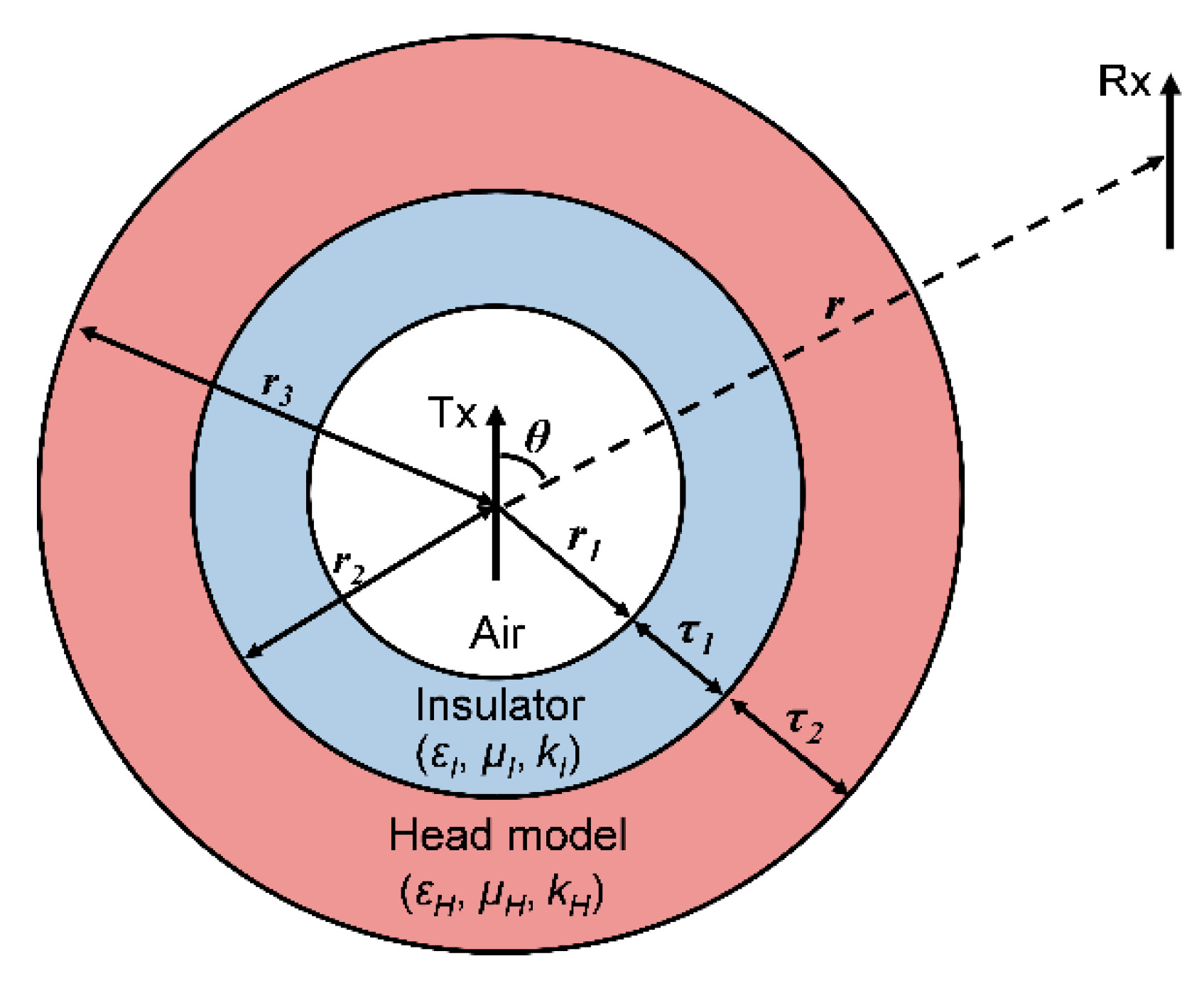
2.1. The Derivation of an Analytical Soultion

First, we constructed an MSS consisting of three sections; namely, air, insulator and head (Figure 1), to analyze the influence of the implanted antenna’s insulating layer on MPTE. That MSS configuration was the same as the configuration used in [8]. The head section was filled with a homogeneous material that can satisfactorily replace an inhomogeneous model [12]. The homogeneous, frequency-dependent material properties of the head layer were based on the SAR values reported in [17]. Spherical shell models have been used in deriving analytic solutions for various situations of power loss due to the lossy material with the antenna [8,9,10,11,12,13,14,15]. In particular, it has been shown in [11] that the electric field intensity values of a brain-implanted antenna calculated from an MSS model and from a numerical head phantom are very close. In this work, a transmitting antenna (Tx) surrounded by an insulator was immersed inside a head shell, and the receiving antenna (Rx) was located outside the MSS.
A spherical wave radiator located in an unbounded lossy medium should be isolated from that medium through a lossless layer [14,15]. Otherwise, infinite power must be supplied for a Hertzian dipole to radiate [8]. In order to obtain meaningful results from our analysis of the insulating layer, we located the Tx in a region of lossless air, as depicted in Figure 1. The distance between the Tx and the Rx is r, and the position of the Rx with respect to the Tx is expressed as θ . The radius of the air layer is r1; the radius of the insulator is r2 with a thickness of τ1; and the radius of the overall head model is r3 with a thickness of τ2, meaning that r = r1 + τ1 + τ2. The wave propagation constants for the insulator and the head are k I = ω μ I ε I and k H = ω μ H ε H , respectively.
To derive MPTE between the Tx and the Rx in the given MSS model, the theoretical upper bound of MPTE between two small antennas in free space in [18] was utilized, given as:
M P T E f s = | X | 2 2 R e [ X 2 ] + 4 ( 1 R e [ X 2 ] ) I m [ X 2 ] 2 X = η e f f · T T = 3 2 · [ s i n 2   θ 1 j k 0 r + ( 3 c o s 2   θ 1 ) · ( 1 ( j k 0 r ) 2 + 1 ( j k 0 r ) 3 ) ] · e j k 0 r ,
where η e f f is the antenna radiation efficiency, r is the distance between the antennas, and k 0 = ω μ 0 ε 0 is the wave propagation constant in free space. An optimal load to achieve maximum coupling is established at the Rx, and the lowest spherical TM10 or TE10 radiation mode from an electrically small antenna is assumed. This assumption holds true for the present work because the electrical size of the implanted antenna should be limited to being very small.
To extend MPTE in free space to the MSS model, we first calculate the field intensity from the Tx outside of the MSS. To this end, vector potentials in each region of the MSS are defined. The electric vector potential when the Tx radiates in TE10 mode can be defined as:
F r = { P 1 ( c o s   θ ) · [ 1 · H ^ 1 ( 2 ) ( k 0 r ) + a T E J ^ 1 ( k 0 r ) ] ( r r 1 ) P 1 ( c o s   θ ) · [ b T E · J ^ 1 ( k I r ) + C T E Y ^ 1 ( k I r ) ] ( r 1 r r 2 ) P 1 ( c o s   θ ) · [ d T E · J ^ 1 ( k H r ) + e T E Y ^ 1 ( k H r ) ] ( r 2 r r 3 ) P 1 ( c o s   θ ) · f T E H ^ 1 ( 2 ) ( k 0 r ) ( r 3 r )
where H ^ n ( 2 ) ( x ) = x h n ( 2 ) ( x ) is the alternative spherical Hankel function of the second kind, and J ^ n ( x ) = x j n ( x ) and Y ^ n ( x ) = x y n ( x ) are the alternative, spherical Bessel functions of the first and second kinds [19] (page 460), respectively. We assume e j w t time dependence. Further, aTE is the amplitude coefficient of the standing wave in the air region ( r r 1 ); bTE and cTE are the standing wave coefficients of the insulator ( r 1 r r 2 ); dTE and eTE are the coefficients of the standing waves in the head layer ( r 2 r r 3 ); and the coefficient fTM is for the outgoing wave external to the MSS ( r r 3 ). We set n to be 1 since the Tx and the Rx are assumed to radiate only the lowest TE10 mode due to their small size. The coefficient values can be determined using the boundary condition of the tangential components of EΦ and Hθ defined by the Fr at every interface of the region is continuous. In this way, the following matrix can be obtained as:
1 ε 0 J ^ 1 ( k 0 r 1 ) 1 ε I J ^ 1 ( k I r 1 ) 1 ε I Y ^ 1 ( k I r 1 ) 0 0 0 k 0 ε 0 μ 0 J ^ 1 ( k 0 r 1 ) k I ε I μ I J ^ 1 ( k I r 1 ) k I ε I μ I Y ^ 1 ( k I r 1 ) 0 0 0 0 1 ε I J ^ 1 ( k I r 2 ) 1 ε I Y ^ 1 ( k I r 2 ) 1 ε H J ^ 1 ( k H r 2 ) 1 ε H Y ^ 1 ( k H r 2 ) 0 0 k I ε I μ I J ^ 1 ( k I r 2 ) k I ε I μ I Y ^ 1 ( k I r 2 ) k H ε H μ H J ^ 1 ( k H r 2 ) k H ε H μ H Y ^ 1 ( k H r 2 ) 0 0 0 0 1 ε H J ^ 1 ( k H r 3 ) 1 ε H Y ^ 1 ( k H r 3 ) 1 ε 0 H ^ 1 ( 2 ) ( k 0 r 3 ) 0 0 0 k H ε H μ H J ^ 1 ( k H r 3 ) k H ε H μ H Y ^ 1 ( k H r 3 ) k 0 ε 0 μ 0 H ^ 1 ( 2 ) ( k 0 r 3 ) · a T E b T E c T E d T E e T E f T E = 1 ε 0 H ^ 1 ( 2 ) ( k 0 r 1 ) k 0 ε 0 μ 0 H ^ 1 ( 2 ) ( k 0 r 1 ) 0 0 0 0
Next, to extend MPTE in free space to the MSS model using the obtained coefficients, we define the shell efficiency, η s h e l l , which shows the ratio between the input power of the Tx and the power radiating out of the shell as:
η s h e l l = P o u t s h e l l P i n s h e l l ,
where P i n s h e l l is the input power of the Tx in the air region from:
P i n s h e l l = 1 2 R e [ E r < r 1 × H r < r 1 * ] · d S = 4 3 π η 0 · R e [ j { H ^ 1 ( 2 ) ( k 0 r ) + a T E · J 1 ^ ( k 0 r ) } · { H ^ 1 ( 2 ) ( k 0 r ) * + a T E * · J ^ 1 ( k 0 r ) * } ] ,
and P o u t s h e l l is the radiating power of the Tx leaving the shell from:
P o u t s h e l l = 1 2 R e [ E r 3 < r × H r 3 < r * ] · d S = 4 3 π η 0 · R e [ j · { f T E · H ^ 1 ( 2 ) ( k 0 r ) · f T E * · H ^ 1 ( 2 ) ( k 0 r ) * } ]
Ultimately, the MPTE of the MMS model is obtained by multiplying the MPTE in free space by η s h e l l . The final expression is, thus, given by:
M P T E s h e l l = η s h e l l × M P T E f s .
MPTE for TM modes can also be derived using duality. It is worth noting that the described derivation procedure follows the work in [20] which solved the case of TM radiation separated by a single shell.

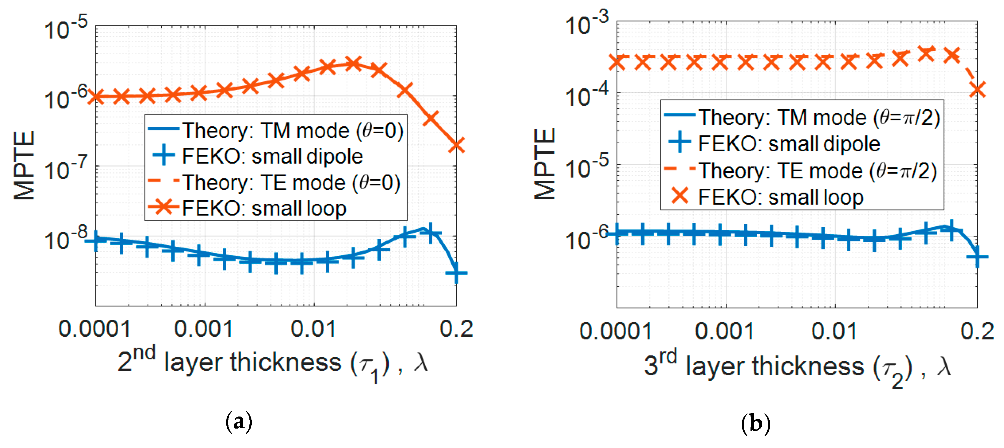
2.2. Validation of the Analytical Solution Using a Numerical Simluator

We used the numerical simulator FEKO by Altair to verify the derived MPTE expressions. The FEKO simulation uses λ/200-long dipoles for both the Tx and Rx radiating TM10 waves and loops with a diameter of λ/200 radiating TE10 waves, as shown in Figure 2, where λ is the free space wavelength. A perfect electric conductor was used for the dipoles and loops (i.e., η e f f = 1 ), and an optimal Linville load for maximum coupling of a two-port network was loaded at the Rx [21] (page 476). In the validation, we considered a dielectric material without magnetic loss (εr″ ≠ 0; μr″ = 0) since the human head is a generally electrically lossy medium with no magnetic loss [22].
The validation results are shown in Figure 3. Specifically, Figure 3a presents the MPTE values according to insulator thickness (τ1) when r and θ are fixed as 1.0 λ and 0, respectively. The radius of the air-filled region containing the antenna (r1) was 0.005 λ and the thickness of the head layer (τ2) was fixed at 0.05 λ, and τ1 was changed from 0.0001 λ to 0.2 λ. The free-space region was set with material properties of εr = 1.0 and tanδ = 0.0. The insulating and head layers of the MSS were set with εr and tanδ values of 5.0 and 1.0 and 10 and 5.0, respectively. The values were arbitrarily chosen in the validation. With θ at π/2, the insulator properties were then changed to εr = 3.0 and tanδ = 0.5, and those of the head layer to εr = 5.0 and tanδ = 1.0, and the resulting MPTE values are shown in Figure 3b. Then, τ1 was fixed at 0.05 λ and τ2 was varied from 0.0001 λ to 0.2 λ. In Figure 3a,b, it can be seen that the MPTE values derived from the proposed solution and from the numerical simulations show good agreement.
Whether or not the MSS model can accurately represent an antenna implanted in the head may be questioned, since the antenna is located at the center of the MSS, while it would be close to the top of the head in practice. To address this question and justify the model used here, we compare the calculations from our solution with numerical values when the Tx is located towards the top of the spherical model (Figure A1 and Figure A2). It can be observed that the overall tendency is largely matched with only a small difference of 1–2 dB.

3. Insulator Layer and Radiation Mode

In this section, we analyze the effect of the material properties and size of the insulator on MPTE using the derived closed-form expression to find the optimal configuration and radiation mode for implanted antennas. The frequencies of 403.5 MHz, 2.4 GHz and 5.8 GHz were chosen for this analysis. Table 1 presents the properties of commercially available biocompatible insulators and of the homogenous head layer in the MSS; the radius of the overall MSS (r3) was fixed at 9 cm [8,9,10,11,12,13]. Although the characteristics of the biocompatible materials in Table 1 could have been frequency dependent, they were set as constant in this study for convenience. That is because we focused on the generalized influence from dielectric properties, and the frequency dependence of real, specific material does not have impact on it.
Table 2 shows the calculated MPTE values using the derived solution for TM mode at 5.8 GHz when r1 and τ1 are both 1 mm and the insulator layer exhibits the dielectric constant and loss tangent of polyamide (i.e., εr = 4.3 and tanδ = 0.004). The external monitoring system could be located either close to or far from the head. The results shown in Table 2 demonstrate that the absolute value of MPTE understandably varies depending on the distance to the Rx from the outer edge of the MSS (r-r3) and the position of the Rx with respect to the Tx (θ). To explore how much improvement might be made by changing the properties of the insulator, we then calculate the relative MPTE (MPTErel) in comparison to an antenna without an insulating layer; that is, the MPTE of an MSS consisting of two layers of air and a homogenous head shell. As presented in Table 2, a clear improvement in MPTE of about 3.9 dB is observed for every case, with little difference between the various antenna distances and angles. In this preliminary study, the insulating layer was, therefore, found to improve MPTE regardless of the relative positions of the transmitting and receiving antennas. Subsequently, we fixed r = 5 m and θ = π/2, considering the situation that a patient and external monitoring system are far apart.

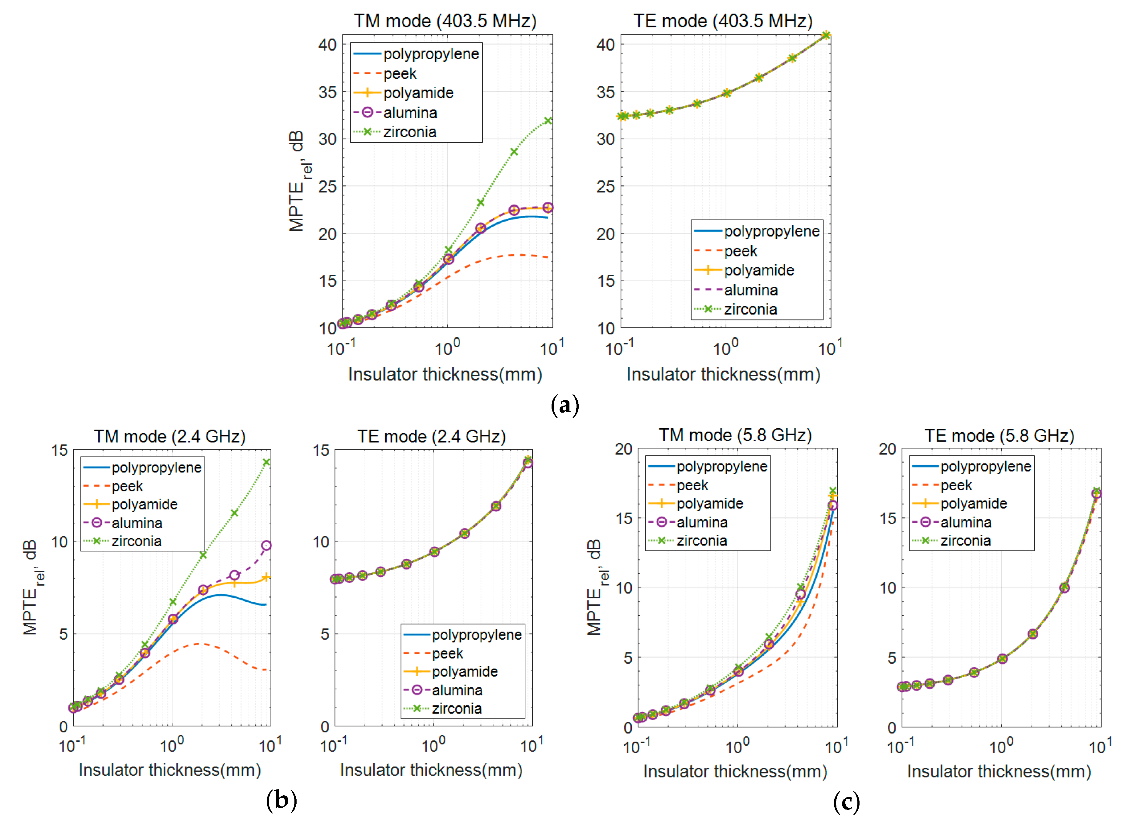
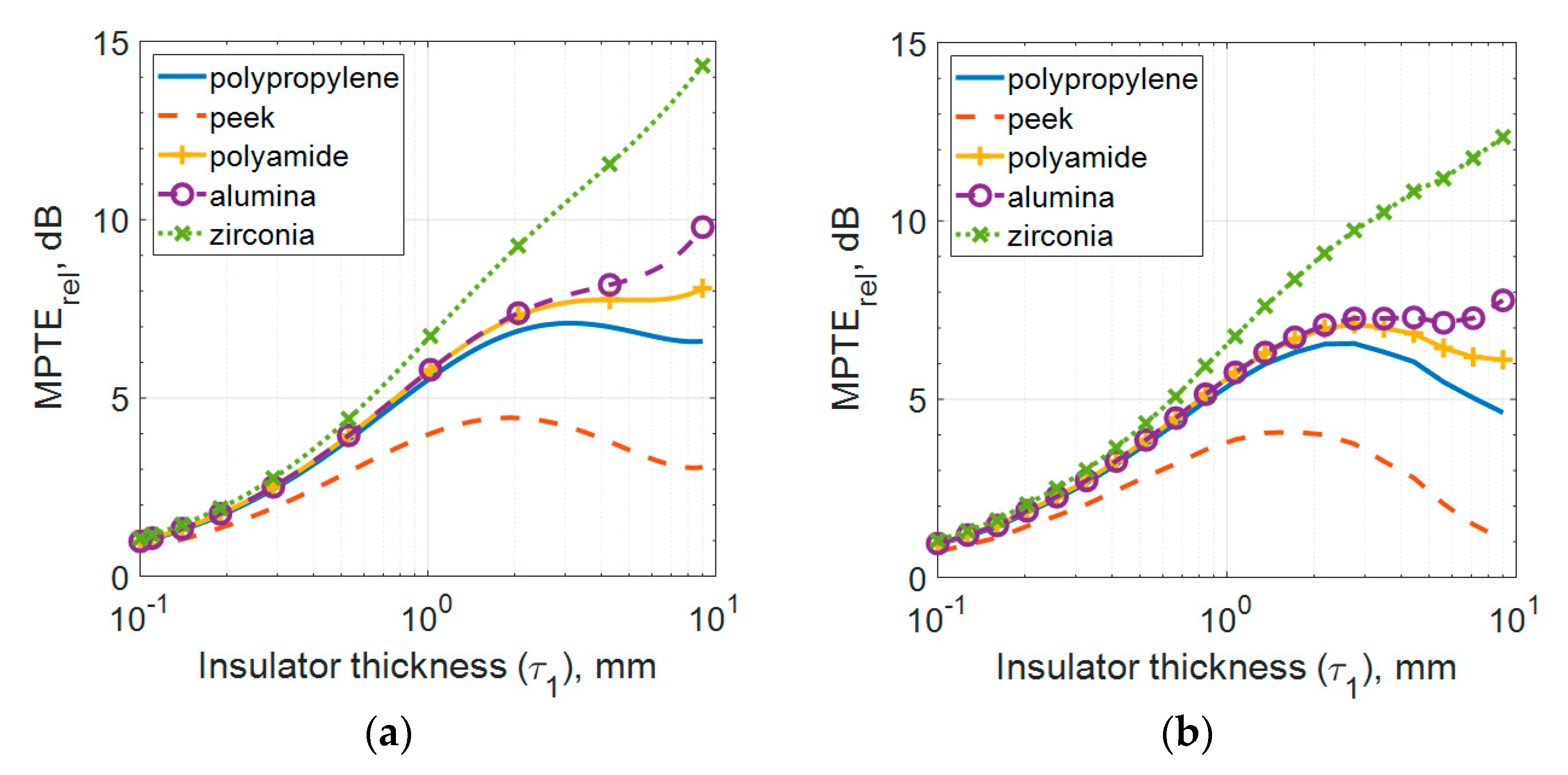
3.1. Effect of the Commercially Biocompatible Insulators

The MPTErel values according to τ1 thickness as it varies from 0.1 to 9 mm are shown in Figure 4 with r1 fixed at 1 mm. Although the insulator thicknesses up to 10 mm is not realistic for implanted antenna designs, such the long study range could show a clearer behavior of MPTE along the thickness. Both TM and TE modes are expressed in MPTErel with respect to the TM mode having no insulating layer. As shown in Figure 4, MPTErel for both TM and TE modes increases as the insulating layer becomes thicker in all frequency bands. In addition, MPTErel differs according to the kind of insulator used for the TM mode, where there is little difference for TE radiation, because the distribution of the magnetic near-field is less affected by the dielectric medium with no magnetic loss than that of the electric near-field.
Due to this characteristic, magnetic TE mode sources are known to be more efficient in power transfer than electric sources in a medium with dielectric loss, such as the human body [8,9,10,15]. However, as observed in Figure 4, the difference in MPTErel by insulator type also becomes smaller for TM radiation as frequency increases.
The stored electric and magnetic energy densities of a small electric dipole according to distance in free space are plotted in Figure 5 to illustrate this phenomenon. The losses caused by MSS are divided into reactive near-field loss, propagating field absorption loss and reflection loss. The biggest influence on the difference between TM mode and TE mode loss is reactive near-field loss [10]. Here, it is shown that electric energy density (we) is dominant closer to the source and that the difference between we and the magnetic energy density (wm) becomes very small at greater distances. The colored areas represent the physical location of the insulating and head layers at each frequency band which occurs, for 403.5 MHz, with we dominating, and, for 5.8 GHz, with the two density levels at almost the same value. Thus, the effect of the insulator is reduced at higher frequencies and the difference in MPTErel also decreases with small deviations between we and wm. These findings from this sub-section can be summarized as follows:
  • MPTErel is higher with thicker insulators.
  • MPTErel of the TM mode varies according to insulator material but is almost negligible for TE radiation.
  • As frequency increases, the effect on MPTErel by insulator type and the difference in both TM and TE mode MPTErel decreases.

3.2. The Effects of Variation in Dielectric Properties of Insulators

In Figure 4, it can also be observed that MPTErel is highest when zirconia, which has the lowest tanδ among the tested materials, is used and that MPTErel is lowest when peek, with the highest tanδ, is utilized. In contrast, alumina shows higher MPTErel than polypropylene and polyamide despite its tanδ being higher. In this section, MPTErel values are compared according to variations in the dielectric constant and loss tangent of the insulator, and this phenomenon is explained.
The MPTErel values for TM mode radiation according to these properties are plotted across τ1 in Figure 6. In Figure 6a, relative permittivity is adjusted while loss tangent is maintained, and in Figure 6b, loss tangent varied while keeping relative permittivity constant. The properties of the head layer still follow those in Table 1. The figures show that higher MPTErel values are obtained as the dielectric constant of the insulator increases and the loss decreases. This explains the high MPTErel of zirconia (Figure 4), which has the highest dielectric constant and the lowest loss tangent among the tested materials. When comparing polypropylene, polyamide and alumina in terms of MPTErel (see Figure 4), it is found that alumina, with its higher loss tangent and higher dielectric constant, shows a higher MPTErel than the other two materials. For polypropylene and peek, also as shown in Figure 4, peek demonstrates a lower MPTErel due to its loss being three times higher, although its dielectric constant is only marginally higher.
We plotted MPTErel against the variations in dielectric constant and loss tangent at 403.5 MHz in Figure 6c to explore which configuration has the greatest impact on MPTErel. Therein, τ1 is fixed at 1 mm because practical insulator thickness is usually around 1 mm [4,5,6,7]. It is interesting to observe that there is significant variation in MPTErel values as tanδ changes when εr is less than 5.0, as with polypropylene, peek and polyamide. In contrast, MPTErel is less affected by relatively large tanδ values when εr is greater than 5.0, as with alumina and zirconia. This explains why alumina, with a higher tanδ, shows better MPTErel than polypropylene and polyamide. Similar trends are observed for higher frequencies, although the effect is not as pronounced as with 403.5 MHz. This can be inferred from the case of 5.8 GHz in Figure 6a,b where the differences between the MPTErel values are not huge.
From the findings presented in this section, it can be said that improvement in MPTErel is not significant when the dielectric constant is greater than 5.0 with an insulator thickness of 1 mm. Materials with a high dielectric constant and low loss are rare and usually expensive, but these findings indicate that materials with a dielectric constant greater than 5.0 are sufficient for selection as the insulating layer, since they will be much less affected from the higher loss tangent.

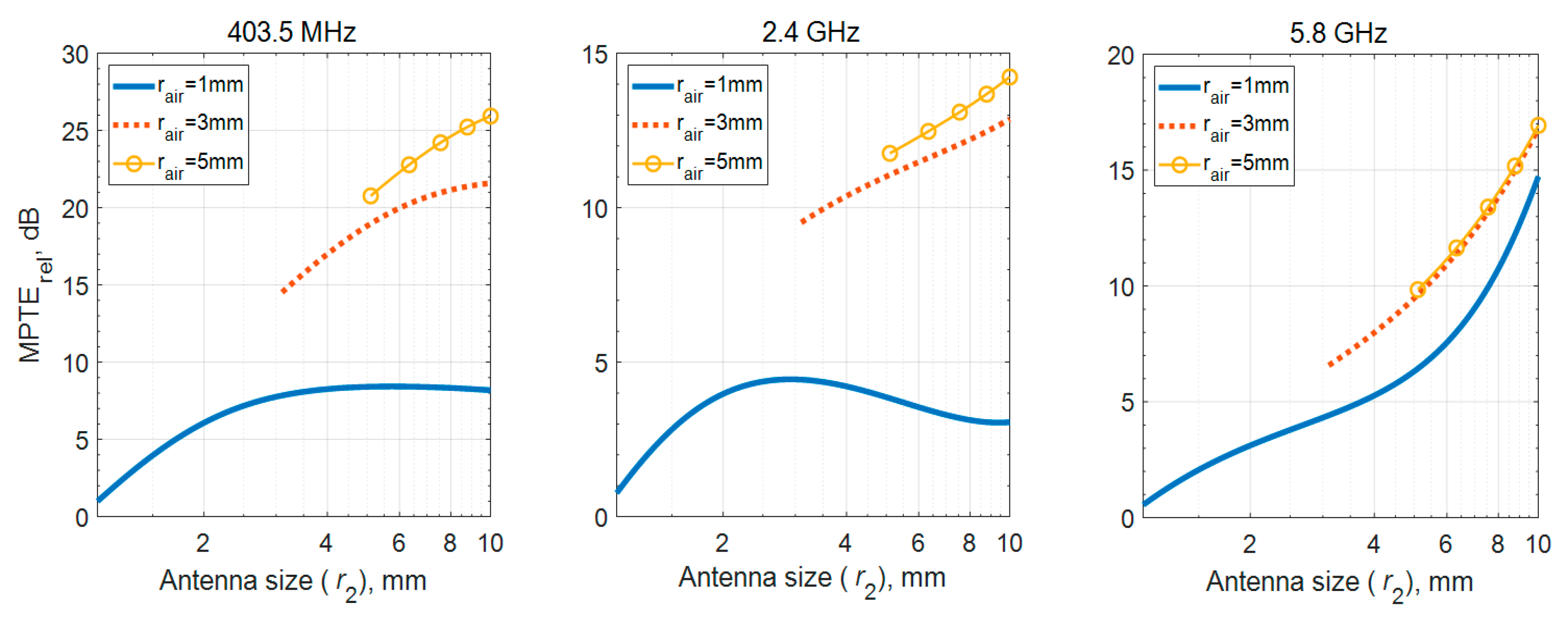
3.3. Lossless Air Region
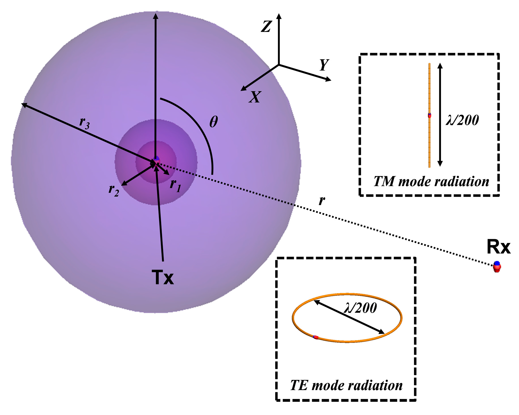
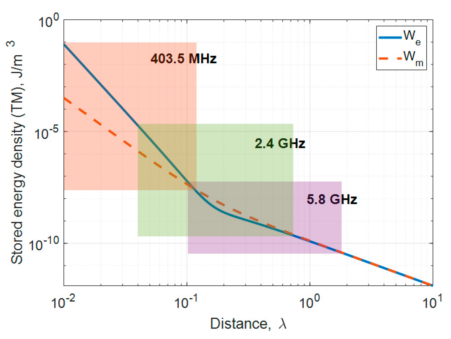
In the MSS model, we placed the Tx in a lossless air region to address the limitations of the small antenna being located in a lossy medium. It was shown in the previous section that MPTErel can be improved with the thicker thickness and higher dielectric constant of the insulating layer. Such a MPTErel improvement is also possible by the increased size of the lossless region [10]. The implanted antenna may be insulated in one of two ways: One is to coat the antenna directly with the insulating material [7], and the other is to place the antenna in a structure such as a capsule, which works as an insulator [4].
The biggest difference between these two insulating methods is the presence or absence of the lossless area. To analyze the effect of the lossless air region, the MPTErel values are compared according to different r1 sizes with the same antenna. Antenna size (r2) combines the thickness of the insulating layer and the radius of the air region. To examine the effect on the MPTErel from the lossless air region clearer, the peek with the lowest MPTErel is chosen as the insulator material. Figure 7 shows the MPTErel according to r2. It is shown that the higher MPTErel values are obtained at the same r2 when the lossless air region is larger, meaning that having more lossless region could be more suitable for increasing MPTErel than using thick insulating layer, as observed from Figure 7. From a practical point of a view, using a capsule to secure the air region should inevitably increase the size, but it can also increase the MPTErel of the antenna immersed in the lossy medium. If a thin and rigid cover could be built for a planar implanted antenna, it not only improve antenna radiation properties but also work as insulation.

3.4. Radiation Mode

As previously outlined, it is known that a magnetic source in the human body is less affected than an electrical source. However, as shown in Section 3.1, the difference between TM and TE radiation modes decreases as frequency increases for a model with a specific physical size. In addition, the upper bound of radiation efficiency for a TE10 mode dipole has been found to be limited [23]. Thus, we compare MPTErel for the different radiation modes using zirconia, which has the highest dielectric constant and lowest loss, and a fixed r1 of 5 mm. As shown in Figure 8, the MPTErel of the TE mode appeared several dB higher than TM at 403.5 MHz, whereas no big differences were observed at 2.4 GHz or 5.8 GHz. These results assume 100% radiation efficiency. However, antennas made of metals with finite conductivity such as copper, should present an upper limit to radiation efficiency obtainable from the finite electrical antenna size. When the antenna is electrically small, the radiation efficiency of the TE mode is significantly lower than that of the TM mode. For example, whereas TE mode radiators could be designed to have radiation efficiency close to 100% at 2.4 GHz and 5.8 GHz with 10 mm of the maximum dimension of the antenna, but at 403.5 MHz only 4.4%, according to [23]. An implanted antenna at 403.5 MHz must be very small and thin which will affect MPTErel.
Furthermore, an electrically small antenna has a minimum Q bound depending on its size, and the Q value of a TE mode antenna is twice as high as a TM mode antenna of the same size [24]. In order to overcome the narrow bandwidth limitation of such antennas, they are designed either in a relatively complex three-dimensional configuration [25,26,27] or with an active circuit such as a non-Foster element [28,29]. Thus, considering actual antenna design, TM mode may be more suitable across each frequency band.

4. Conclusions

In this study, the influence of the insulating layer of an implanted transmitting antenna on the relative maximum power transfer efficiency to an external receiving antenna was analyzed through a derived analytic solution. Theoretical MPTE values were obtained using an MSS model which separates the Tx and Rx antennas using spherical wave theory. The derived expression was validated through the full-wave EM simulator FEKO. The effects of the insulating layer on MPTErel at 403.5 MHz, 2.4 GHz and 5.8 GHz were analyzed using variance in dielectric properties, different insulator sizes, and possible radiation modes.
The insulating material has very small effects on TE mode radiation, but there is a meaningful difference in MPTErel in the case of the TM mode. In TM mode, it was shown that a higher dielectric constant can produce a higher MPTErel value. This property holds true even for a material with a higher loss tangent if its dielectric constant is greater than 5.0. It was also shown that the loss tangent does not have a significant impact on MPTErel when the dielectric constant is very high. However, for low dielectric constants, the effects of the surrounding lossy material become significant. This general behavior explains the different MPTErel values derived from commercially available biocompatible insulating materials. Next, the proper layout of the insulator was discussed as inferred from the size of the air region around the Tx in the MSS model. It was shown that MPTErel was improved when the lossless air region increased. It will be challenging to create such an antenna within a thin and rigid cover, but using the novel design methods of 3D printing technologies, we hope to present further results imminently. Finally, it was shown that MPTErel differed by radiation mode. For perfect radiation efficiency, the TE mode shows higher MPTErel at 403.5 MHz, whereas the values are approximately equal with TM radiation for the higher frequencies. When taking into account the limited upper radiation efficiency bound of a small TE mode antenna, however, the achievable MPTErel becomes significantly lower, leading to the conclusion that a small TM10 antenna would be more effective across all possible medical bands in terms of power transfer efficiency. Overall, optimum insulator design and radiation mode were thoroughly investigated, and the results of this study represent robust design guidelines for increasing the reliability of wireless biotelemetry systems involving brain-implanted antennas.

Author Contributions

Conceptualization, G.S. and I.-J.Y.; methodology, G.S. and I.-J.Y.; software, G.S. and I.-J.Y.; validation, G.S. and I.-J.Y.; formal analysis, G.S. and I.-J.Y.; investigation, G.S. and I.-J.Y.; resources, G.S. and I.-J.Y.; data curation, G.S. and I.-J.Y.; writing—original draft preparation, G.S.; writing—review and editing, I.-J.Y.; visualization, G.S.; supervision, I.-J.Y. All authors have read and agreed to the published version of the manuscript.

Funding

This research was supported by Institute of Information and communications Technology Planning and Evaluation (IITP) grant funded by the Korea government (MSIT) (number 2017-0-00659, Brain implanted bio-telemetry platform for brain signal sensing and monitoring).

Conflicts of Interest

The authors declare no conflict of interest.

Appendix A

In Section 3, the insulating layer of the implanted antenna was analyzed using an MSS model. The biggest limitation of our MSS is that the Tx is at the center of the shell where it would be located near the top of the head in practice. In order to demonstrate that the conclusions using the derived solution are applicable to an actual implanted antenna, we compare an off-center Tx simulation where the antenna is not centered but close to the edge of the shell in Figure A1.
Figure A1. Off-center Tx model: (a) conceptual diagram; (b) model used for FEKO simulation.
Sensors 20 00242 g0a1
Figure A1a is a conceptual diagram of the Tx off-center by a certain distance, and the actual simulation model is shown in Figure A1b. The r1 is fixed at 1 mm and moved so that the outermost edge of the antenna is 10 mm away from the top edge of the outer layer. The Rx is in parallel with Tx and is 5 m away. An electric dipole measuring λ/125 in length with a radius of 1 mm is used. Figure A2a repeats Figure 4b, and Figure A2b compares the simulation results of Figure A1b under the same conditions. As can be seen, the MPTErel values of either case deviate by just 1–2 dB, and, importantly, the tendency is well maintained.
According to [9,30] the radiating power of the implanted antenna is higher when the TM or TE dipole stands parallel to the shell edge and when the source antenna is located closer to the shell edge. In other words, MPTErel is dependent on both the polarization of the electric field joining the MSS edge and the variation of the propagation path. The MPTErel decreases for the off-set case in Figure A2b compared to Figure A2a despite that the Tx is located closer to the edge (see. Figure A1b), because Tx dipole is no more parallel to the shell edge but is very tilted. The fact that the insulating layer mostly affects the mismatch at the adjacent boundary of the head layer [8] can explain the same trend of the graphs in Figure A2a,b.
Figure A2. MPTErel results with commercially available biocompatible materials as an insulating layer at 2.4 GHz: (a) Figure 4b; (b) results of the off-center Tx model.
Sensors 20 00242 g0a2

Appendix B

A list of acronyms and abbreviations is given in Table A1 for the convenience of the readers.
Table A1. List of acronyms and abbreviations.
Acronym (Abbreviation)Definition
MPTEmaximum power transfer efficiency
MICSmedical implant communication system
ISMindustrial, scientific and medical
UWBultra-wideband
MSSmulti-layered spherical shell
Txtransmitting antenna
Rxreceiving antenna
MPTErelrelative maximum power transfer efficiency

References

  1. Lee, C.W.L.; Kiourti, A.; Chae, J.; Volakis, J.L. A high-sensitivity fully passive neurosensing system for wireless brain signal monitoring. IEEE Trans. Microw. Theory Tech. 2015, 63, 2060–2068. [Google Scholar] [CrossRef]
  2. Kiourti, A.; Lee, C.W.L.; Chae, J.; Volakis, J.L. A wireless fully passive neural recording device for unobtrusive neuropotential monitoring. IEEE Trans. Biomed. Eng. 2016, 63, 131–137. [Google Scholar] [CrossRef] [PubMed]
  3. Song, L.; Rahmat-Samii, Y. An end-to-end implanted brain-machine interface antenna system performance characterizations and development. IEEE Trans. Antennas Propag. 2017, 65, 3399–3408. [Google Scholar] [CrossRef]
  4. Merli, F.; Bolomey, L.; Zürcher, J.-F.; Corrandini, G.; Meurville, E.; Skrivervik, A.K. Design, realization and measurements of a miniature antenna for implantable wireless communication system. IEEE Trans. Antennas Propag. 2011, 59, 3544–3555. [Google Scholar]
  5. Kiourti, A.; Nikita, K.S. Miniature scalp-implantable antennas for telemetry in the MICS and ISM bands: Design, safety considerations and link budget analysis. IEEE Antennas Propag. 2012, 60, 3568–3575. [Google Scholar] [CrossRef]
  6. Liu, C.; Guo, Y.-X.; Xiao, S. Capacitively loaded circularly polarized implantable patch for ISM band biomedical applications. IEEE Tans. Antennas Propag. 2014, 62, 2407–2417. [Google Scholar] [CrossRef]
  7. Bahrami, H.; Mirbozorgi, S.A.; Ameli, R.; Rusch, L.A.; Gosselin, B. Biological channel modeling and implantable UWB antenna design for neural recording systems. IEEE Trans. Biomed. Eng. 2015, 62, 88–98. [Google Scholar] [CrossRef]
  8. Merli, F.; Fuchs, B.; Mosig, J.R.; Skrivervik, A.K. The effect of insulating layers on the performance of implanted antennas. IEEE Trans. Antennas Propag. 2011, 59, 21–31. [Google Scholar]
  9. Bosiljevac, M.; Sipus, Z.; Skrivervik, A.K. Propagation in finite lossy media: An application to WBAN. IEEE Antennas Wireless Propag. Lett. 2015, 14, 1546–1549. [Google Scholar] [CrossRef]
  10. Skrivervik, A.K.; Bosiljevac, M.; Sipus, Z. Fundamental limits for implanted antennas: Maximum power density reaching free space. IEEE Trans. Antennas Propag. 2019, 67, 4978–4988. [Google Scholar] [CrossRef]
  11. Kim, J.; Rahmat-Samii, Y. Implanted antennas inside a human body: Simulations, designs, and characterizations. IEEE Trans. Microw. Theory Tech. 2004, 52, 1934–1943. [Google Scholar] [CrossRef]
  12. Nikita, K.S.; Stamatakos, G.S.; Uzunoglu, N.K.; Karafotias, A. Analysis of the interaction between a layered spherical human head model and finite-length dipole. IEEE Trans. Microw. Theory Tech. 2000, 48, 2003–2012. [Google Scholar]
  13. Reyhani, S.M.S.; Ludwig, S.A. An implanted spherical head model exposed to electromagnetic fields at a mobile communication frequency. IEEE Trans. Biomed. Eng. 2006, 53, 2092–2101. [Google Scholar] [CrossRef]
  14. Tai, C.T.; Collin, R.E. Radiation of a Hertzian dipole immersed in a dissipative medium. IEEE Trans. Antennas Propag. 2000, 48, 1501–1506. [Google Scholar] [CrossRef]
  15. Karlsson, A. Physical limitations of antennas in a lossy medium. IEEE Trans. Antennas Propag. 2004, 52, 2027–2033. [Google Scholar] [CrossRef]
  16. Shin, G.; Yoon, I.-J. Analytic study on the small antennas coupling for wireless biotelemetry. In Proceedings of the International Symposium on Antennas and Propagation (ISAP 2018), Busan, Korea, 23–26 October 2018. [Google Scholar]
  17. Evaluating Compliance with FCC Guidelines for Human Exposure to Radiofrequency Electromagnetic Fields, 97-01 ed.; Supplement C, OET Bulletin 65; Federal Communication Commission (FCC) Std.: Washington, DC, USA, 2001.
  18. Lee, J.; Nam, S. Fundamental aspects of near-field coupling small antennas for wireless power transfer. IEEE Trans. Antennas Propag. 2010, 58, 3442–3449. [Google Scholar]
  19. Harrington, R.F. Time-Harmonic Electromagnetic Fields; IEEE Press: New York, NY, USA, 2001; p. 460. [Google Scholar]
  20. Yoon, I.-J.; Ling, H. Investigation of near-field wireless power transfer in the presence of lossy dielectric materials. IEEE Trans. Antennas Propag. 2013, 61, 482–488. [Google Scholar] [CrossRef]
  21. Balanis, C.A. Antenna Theory: Analysis and Design, 3rd ed.; Wiley-Interscience: New York, NY, USA, 2005; pp. 476–478. [Google Scholar]
  22. Drossos, A.; Santomaa, V.; Kuster, N. The dependence of electromagnetic energy absorption upon human head tissue composition in the frequency range of 300–3000 MHz. IEEE Trans. Microw. Theory Tech. 2000, 48, 1988–1995. [Google Scholar]
  23. Pfeiffer, C. Fundamental efficiency limits for small metallic antennas. IEEE Trans. Antennas Propag. 2017, 65, 1642–1650. [Google Scholar] [CrossRef] [Green Version]
  24. Thal, H.L., Jr. New radiation Q limits for spherical wire antennas. IEEE Trans. Antennas Propag. 2006, 54, 2757–2763. [Google Scholar] [CrossRef]
  25. Best, S.R. The radiation properties of electrically small folded spherical helix antennas. IEEE Trans. Antennas Propag. 2004, 52, 953–960. [Google Scholar] [CrossRef]
  26. Kong, M.; Shin, G.; Lee, S.-H.; Yoon, I.-J. Investigation of 3D printed electrically small folded spherical meander wire antenna. J. Electromagn. Eng. Sci. 2017, 17, 228–232. [Google Scholar] [CrossRef] [Green Version]
  27. Kim, O.S. Low-Q electrically small spherical magnetic dipole antennas. IEEE Trans. Antennas Propag. 2010, 58, 2210–2217. [Google Scholar] [CrossRef] [Green Version]
  28. Ha, S.-G.; Cho, J.; Jung, K.-Y. Design of miniaturized microstrip patch antennas using non-Foster circuits for compact controlled reception pattern antenna array. J. Electromagn. Eng. Sci. 2017, 17, 108–110. [Google Scholar] [CrossRef]
  29. Yoon, I.-J.; Christensen, S.; Zhurbenko, V.; Kim, O.S.; Breinbjerg, O. Non-Foster impedance matching sensitivity of electrically small electric and magnetic spherical dipole antennas. Electron. Lett. 2016, 52, 996–998. [Google Scholar] [CrossRef] [Green Version]
  30. Nikolayev, D.; Zhadobov, M.; Karban, P.; Sauleau, R. Electromagnetic radiation efficiency of body-implanted devices. Phys. Rev. Appl. 2018, 9, 024033. [Google Scholar] [CrossRef] [Green Version]
Figure 1. Multi-layered spherical shell (MSS) model for a brain-implanted antenna (Tx) with a receiver antenna (Rx) outside the model.
Sensors 20 00242 g001
Figure 2. FEKO simulation setup for verification of the derived solution.
Sensors 20 00242 g002
Figure 3. Maximum power transfer efficiency (MPTE) results using the derived theory and FEKO simulation according to (a) the thickness of the insulting layer (τ1) and (b) the thickness of the head layer (τ2).
Sensors 20 00242 g003
Figure 4. MPTErel results with different commercially available biocompatible materials as the insulating layer: (a) 403.5 MHz; (b) 2.4 GHz; (c) 5.8 GHz.
Sensors 20 00242 g004
Figure 5. Stored electric and magnetic energy densities of a small dipole antenna.
Sensors 20 00242 g005
Figure 6. MPTErel results according to dielectric properties: (a) varying dielectric constant with stable loss tangent; (b) varying loss tangent with stable dielectric constant; (c) variations in εr and tanδ at 403.5 MHz.
Sensors 20 00242 g006
Figure 7. MPTErel results according to antenna size adjusted by air region.
Sensors 20 00242 g007
Figure 8. MPTErel results when the insulator layer is composed of zirconia, which is the optimal material based on previous results.
Sensors 20 00242 g008
Table 1. Material properties of biocompatible insulators and the homogenous head layer.
MaterialDielectric Constant (εr)Loss Tangent (tanδ)
Polypropylene *2.550.003
Peek *3.200.010
Polyamide *4.300.004
Alumina *9.200.008
Zirconia *29.00.002
Head tissue (400 MHz)43.50.799
Head tissue (2.4 GHz)39.20.344
Head tissue (5.8 GHz)35.30.463
* biocompatible material. Note: the biocompatible materials are dependent on frequency but were set to be frequency independent in this study.
Table 2. Absolute and relative MPTE results by distance and angle between Tx and Rx when insulator is polyamide at 5.8 GHz.
MPTE
(Absolute)
MPTE
(w/o Insulator)
Improved MPTE
(Relative)
rr3 = 1 cm
and θ = 0
1.11 × 10−174.51 × 10−183.911 dB
rr3 = 1 cm,
and θ = π/2
1.64 × 10−246.67 × 10−253.907 dB
rr3 = 5 m,
and θ = 0
4.01 × 10−161.63 × 10−163.910 dB
rr3 = 5 m,
and θ = π/2
1.57 × 10−196.38 × 10−203.911 dB

