Abstract
The negative pressure wave (NPW) signals generated by a pipeline leakage often have a long signal duration. When these signals are utilized to compute the leakage position, the long signal duration will result in a large area being considered as leakage area. The localization resolution is low. A novel high-resolution localization algorithm is developed for pipeline leakage detection using piezoceramic transducers in this paper. The proposed algorithm utilizes multiple temporal convolutions to decrease the localization functional values at the points close to the leakage, in order to reduce the range of the leakage area revealed by the proposed algorithm. As a result, the localization resolution is improved. A measured experiment was conducted to study the proposed algorithm. In the experiment, the proposed algorithm was used to monitor a 55.8 m pressurized pipeline with two controllable valves and two Lead Zirconate Titanate (PZT) sensors. With the aid of the piezoceramic sensor, the experimental results show that the proposed algorithm results in a resolution which is better than that of the traditional method.
1. Introduction
As a multi-disciplinary research field [1,2,3,4], structural health monitoring (SHM) is applied in multiple areas [5,6,7]. SHM technology can evaluate the condition of structural health and, through appropriate data processing and interpretation, issue early warning, if needed. Recently, structural health monitoring with Lead Zirconate Titanate (PZT) transducer has gained extensive attraction [8,9]. PZT transducers can exchange energy between mechanical energy and electrical energy [10,11], and therefore, they can work as an actuator to general stress or ultrasonic waves or a sensor to detect such waves [12,13,14,15]. PZTs are often used to build vibrations sensors, such as accelerometers, for vibration detection and control [16,17], as well as ultrasonic transducers [18,19,20] and acoustic emission probes [21,22,23] for SHM. Furthermore, this type of transducer can be bonded onto a structural surface or embedded in a concrete or composite structure during the structural fabrication process.
The SHM with PZT transducer can be performed by using several methods. One method is based on wave propagation [24]. Usually, two PZT transducers are integrated with the monitoring structures: one works as the actuator, and the other works as the receiver. By analyzing the energy change of the received signal, the health status of the structures can be evaluated. A number of SHM investigations have been adopted that have a monitoring scheme, such as the bolt connection status and bolt loosening monitoring [25,26,27], the damage evaluation [28,29,30] and detection [31,32], bonding status monitoring of composite structures [33,34,35,36], grouting compactness monitoring [37,38,39]. Furthermore, to obtain the detail of the structural damage, some investigators developed imaging algorithms which process the wave signals captured by a PZT transducer array to reveal damages of the structures [40,41,42,43]. In addition to the active SHM based on PZT, the PZT transducers are also employed for passive monitoring. For example, PZT sensor arrays were used to detect and localize the impact on various structures [44,45]. Another type of PZT application is based on electromechanical impedance (EMI) [46,47,48]. EMI is widely used for the health monitoring of various structures, for example, strength development monitoring of cementitious material [49], cable force monitoring in tendon-anchorage [50], bolt-joint structural health monitoring [51], impedance monitoring in tendon-anchorage [52], and local strand-breakage detection in multi-strand anchorage system [53]. Furthermore, the performance of EMI based SHM method can be improved by using multilevel wavelet decomposition [54], metamaterial plasmons [55], artificial neural networks [56] and fuzzy network [57], locally resonant piezoelectric metastructure [58] and so on.
As an important part of infrastructure, pipelines play an important role in a nation’s economy. However, pipelines are subjected to adverse factors, such as impacts and corrosion [59,60,61,62], which may lead to leakage. Since leakages in pipelines can cause serious accidents, PZT transducers have been widely used for pipeline leakage detection to provide early warning [63,64,65,66], taking their advantages of wide bandwidth and dual actuating and sensing capacities. When a leakage occurs, the negative pressure wave (NPW) [67], which is generated by the leak, propagates toward both sides of the pipeline and is captured by PZT transducers. By analyzing the NPW signals, the leakage’s location can be revealed. For instance, Zhao et al. [68] developed a wavelet analysis based leak localization method of the natural gas pipeline. Hu et al. [69] developed a harmonic wavelet-based pipeline small leakage detection method with noise suppression. Liu et al. [70] proposed a new leak detection and location method based on the propagation law of leakage acoustic waves.
Time reversal (TR) can make the signals focus on the signal source by the physical method [71,72,73] or by computation [74,75,76,77]. Therefore, a lot of localization methods based on time reversal are developed. Zhao et al. proposed a cross-sectional scanning-based time reversal defect localization method [74]. Zheng et al. developed a unique location-specified signature based high accuracy TR localization approach [75]. Qiu et al. propose a TR localization method which can obtain the impact region image by processing the signals estimated with using the digital sequences [76]. However, when the time reversal method is applied to localize impact region or leakage area, due to the long duration of the impact signal and the leakage signal, the localization method often has a low localization resolution [76,77].
In this paper, a new high-resolution localization algorithm for pipeline leakage detection using PZT transducers and multiple temporal convolutions is developed. The proposed algorithm is based on the temporal characteristic of the back-propagation signal. With using multiple temporal convolutions, the localization functional values at the points close to the leakage drop dramatically. Therefore, the size of the leakage area revealed by the proposed algorithm gets small, and the localization resolution can be improved. The proposed algorithm was employed for the pipeline leakage localization and a measured experiment was executed. The results show that the proposed algorithm can give a good idea of the two leakage positions in a PVC pipeline with 55.8 m length. Moreover, the novel localization algorithm offers a resolution of about 2.5 m which cannot be obtained by using the traditional localization algorithm.
2. Theory of the Proposed Algorithm
For corresponding to the pipeline leakage experiment, a model of pipeline is built to describe the proposed algorithm. For a gas pipeline, an NPW generated by a leakage will propagate from the leakage location to the two ends of the pipeline. Assume that two PZT transducers are used to catch the NPW, and the nth sensor locates at , as shown in Figure 1. A leakage happens at . Assume the time of NPW occurrence is TL. All sensors work synchronously. The Fourier transform of the leakage signal captured by the sensor can be represented as:
where is the Fourier transform of , and is the measured transfer function representative of propagation from the leakage to the sensor. The subscript “o” emphasizes that this is obtained by the experimental approach.
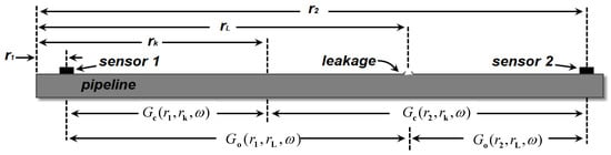
Figure 1.
Model of the proposed algorithm.
First reverse the NPW signal in the time domain. Since inverse a signal in time domain is equivalent to taking the complex conjugate in frequency domain, the inversion version of Equation (1) can be represented as:
where “*” represents the complex conjugate.
Then, the signal back-propagates at the sensor’s position. In the proposed algorithm, the back-propagation is realized via convoluting with , where is the computational transfer function representing the “propagator” from location to generic observation point . The symbol “c” emphasizes that this is computed in software. At the generic observation point of the monitoring domain, the back-propagation signal of the sensor is illustrated as:
Due to the reciprocity of NPW, we can assume that the computational transfer function matches the measured data, namely . All back-propagation signals will focus at the leakage position at the time t = −TL. To cancel TL, the signals will be processed as following. is inversed in time domain and then convolved with . The corresponding output signal can be represented by:
where is the frequency domain expression of , is the frequency domain expression of , “” represents the convolution operation.
is symmetric with respect to the reference time t = 0 at , neither is at other position. For using the focal characteristic of , self-convolution for is carried out as follows:
Design the localization functional as:
The localization functional value of the proposed algorithm at the leakage position is:
The flow diagram of the proposed algorithm is shown in Figure 2.
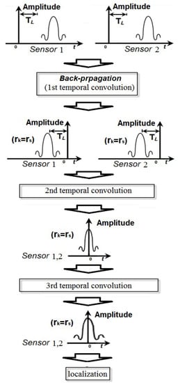
Figure 2.
The flow diagram of the proposed algorithm.
3. Analysis About Resolution Improvement
For pipeline leakage, the localization functional of the traditional time reversal localization algorithm based on the maximum value [77] is represented as follows:
where is the back-propagation temporal signal of the sensor.
The localization functional value of the traditional time reversal localization algorithm at the leakage position is:
Take into account a generic observation point on the pipeline, and then, the computational transfer function at can be represented as:
where is the phase difference between and .
According to Equation (8), the localization functional value of the traditional time reversal localization algorithm at can be represented as:
The localization functional value of the proposed algorithm at can be written as:
where the point is very close to the leak point, namely , approaches to zero, . The generic observation point will be classified as the leakage area. However, due to the superposition of various phase difference and the phase difference amplification of two times, the phase difference in Equation (12) enlarges apparently, decreases. Due to the decrease of the localization functional value at the point close to the leakage, the number of the points considered as the leakage area declines, the leakage area given by the proposed algorithm gets small. Therefore, the localization resolution is improved.
4. Experimental Result and Discussion
As shown in Figure 3, a pipeline with 55.8 m length was composed of five 0.2 m sections, six 9.1 m straight sections and ten 90° elbow connectors. Two PZT sensors with size of 15 mm × 10 mm × 0.4 mm were located at 1.52 m and 54.08 m respectively. The Two PZT sensors were mounted on the outer surfaces of the pipeline by using the super glue [78]. Two valves located respectively at 24.84 m and 34.21 m are used to produce leakage signals. The special locations of the leakages and the sensors are listed in Table 1. The PZT is APC850 whose properties are available from the manufacturer [79]. The parameters of APC850 are shown in Table 2. The data acquisition system is a NI PXI-5105 Digitizer. The equipment was triggered by the voltage signal of the sensor 1 with a −0.02 V trigger level. The sampling rate of the experiment is 100 KS/s. A compressor pumped air into the pipeline, and a leakage was produced when a valve on the pipeline is opened. Then, the PZT sensors caught the leakage signals.
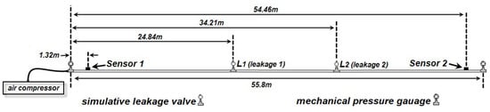
Figure 3.
Schematic diagram of the measured experiment.

Table 1.
Coordinates of sensors and leakages.
Table 2.
Parameters of Lead Zirconate Titanate (PZT) sensor.
The computational transfer function is represented as:
where is the wave number, and is the NPW velocity. In this experiment, the velocity is 300 m/s [63]. For the observation point , we let
denote the distance between the sensor at and the observation point .
The measured data is processed by using the traditional time reversal localization algorithm [77] and the proposed algorithm. It is worthwhile mentioning that the traditional time reversal localization algorithm used the maximum value of time reversed signal to localize the leakage, since the occurrence time of the leakages is unknown. In addition, in the results based on the two methods, the localization functional values are normalized for the purpose of investigating the resolution, as shown in Figure 4. From Figure 4, it can be seen that the traditional time reversal localization algorithm can identify the leakages’ positions. However, since the duration of the signal is long, the time reversed signals still superposed with each other. The localization functional value of the traditional time reversal localization attenuated slowly. Therefore, numbers of points close to the leakages are classified into the leakage area. That means the localization resolution of the traditional time reversal localization algorithm based on the maximum of the time reversed signal declines. On the other hand, the proposed algorithm applies multiple temporal convolutions to increase the phase deference between the signal at the leakage point and the signals at non-leakage points, thus decreasing the localization functional values at the points close to the leakage. That means that fewer points are classified into the leakage area, and the localization resolution is improved.
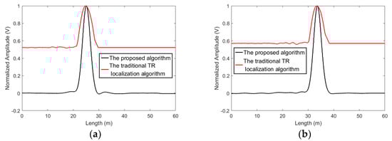
Figure 4.
The localization results obtained by using the proposed algorithm and the traditional time reversal localization algorithm based on the maximum of the time reversed signal. (a) L1 and (b) L2.
The resolution is highly related to the question of the maximum size of leakage areas. It sets a boundary limit between points having different signal signatures. Usually, the boundary is chosen at 0.7 (−3 dB) [77]. The points with localization functional values larger than −3 dB will be classified into the leakage area. As shown in Figure 4, for the traditional time reversal localization algorithm, the −3 dB area of the L1 is from length = 22.8 m to length = 27.9 m and the −3 dB area of the L2 ranges from length = 30.8 m to length = 36.5 m. The resolution of the traditional time reversal localization algorithm is unsatisfied. Using the proposed algorithm, the −3dB area of the L1 covers from length = 23.9 m to length = 26.4 m and the −3 dB area of the L2 is from length = 32.5 m to length = 34.9 m. Apparently, the −3 dB areas based on the proposed algorithm are smaller than those based on the traditional time reversal localization algorithm.
The four extra measured experiments were conducted to investigate repeatability of the proposed algorithm. As shown in Figure 5 and Figure 6, in the all results, the curves of the proposed algorithm are narrower than those of the traditional time reversal localization algorithm at the leakage areas. This means that the repeatable performance can be achieved by using the proposed algorithm.
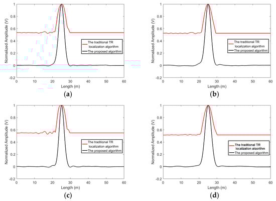
Figure 5.
The four extra experiment results obtained by using the proposed algorithm and the traditional time reversal localization algorithm for Leakage 1, (a) Data 1, (b) Data 2, (c) Data 3, (d) Data 4.
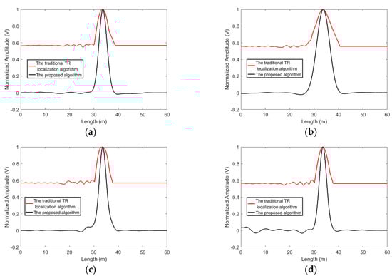
Figure 6.
The four extra experiment results obtained by using the proposed algorithm and the traditional time reversal localization algorithm for Leakage 2. (a) Data 1, (b) Data 2, (c) Data 3, (d) Data 4.
The proposed algorithm can better reject the noise. To compare the proposed algorithm with the traditional time reversal localization algorithm and the algorithm presented in [80], experiments are conducted and the standard white Gaussian noise is added to the acquired signals. The results of the proposed algorithm and the traditional time reversal localization algorithm at SNR = −5 dB and −10 dB are shown in Figure 7 and Figure 8. When SNR = −5 dB, the proposed algorithm can suppress the interference of noise and give a good idea of the leakage’s position. When SNR drops to −10 dB, the noise causes the localization curves of the proposed algorithm to distort. However, the leakage locations can still be distinguished. Contrastingly, in the results based on the traditional time reversal localization algorithm, due to the effect of the noise, the red curves are not smooth. It is difficult to identify the exact location of the leakage.
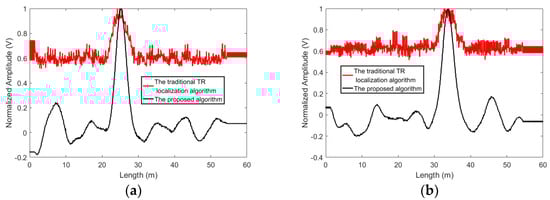
Figure 7.
The localization results obtained by using the proposed algorithm and the traditional time reversal localization algorithm at SNR = −5dB, (a) L1 and (b) L2.
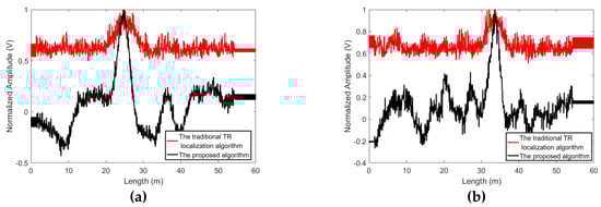
Figure 8.
The localization results obtained by using the proposed algorithm and the traditional time reversal localization algorithm at SNR = −10dB, (a) L1 and (b) L2.
The focusing signal is symmetric with respect to the reference time t = 0 at the leakage location, neither is the noise. Therefore, the proposed algorithm which localizes the leakage by computing the symmetry of the signals can enhance the focusing signal energy and suppress the noise. On the other hand, since the traditional time reversal localization algorithm identified the leak position by superposing the two acquired signals directly, the NPW signals and the noise can be strengthened synchronously via the traditional time reversal localization algorithm. Therefore, the effect of the noise is more remarkable on the results of the traditional time reversal localization algorithm. Additionally, since the algorithm presented in [80] also localized the leakages by superposing the two signals directly, the same influence of the noise can be seen in Figure 9. Obviously, the proposed method can better reject the noise.
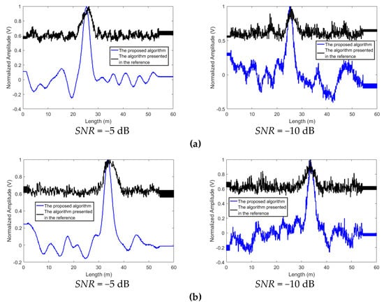
Figure 9.
The localization results obtained by using the proposed algorithm and the method (the parameter p = 1) presented in [80] at various SNRs, (a) L1 and (b) L2.
The L2’s time reversed signals from the two sensors are shown in Figure 10. As shown in Figure 10, at the observation points, the time reversed signals from the two sensors are slowly far from each other, with the increase of the distance between the observation point and the leakage point. At the point of intersection of two waveform curves, the amplitudes of the signals attenuate slowly. Therefore, the maximum signal amplitude of the traditional time reversal localization algorithm at the points close to the leakage position slowly decreases. The waveforms of and at various are shown in Figure 11. Since Equation (7) enlarges the phase of the output signal, the waveform of is further away from the reference time t = 0, as compared to the waveform of . Furthermore, at t = 0, the amplitude of is lower than that of . Therefore, the localization functional values of the proposed algorithm attenuate fast.
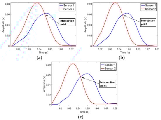
Figure 10.
The L2’s time reversed signals, (a) 34.71 m, (b) 35.21 m, (c) 35.71 m.
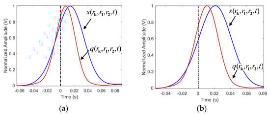
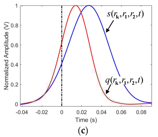
Figure 11.
The waveforms of and at various . (a) = 34.71 m, (b) = 35.21 m, (c) = 35.71 m.
The temperature can affect the acquired signals, and the effect has been investigated [47]. In this experiment, the effect of temperature variation on the performance of the proposed method was not investigated, due to the limitation of the current experiment condition. However, the corresponding investigation will be considered in future work.
5. Conclusions
When the conventional localization algorithms are applied for low frequency signal passive detection, such as pipeline leakage detection, their resolutions will be quite low due to the long signal duration. In this paper, a novel localization algorithm is designed to enhance the resolution of pipeline leakage localization using piezoceramic transducers. Based on the temporal characteristic of the time reversal signals, multiple convolution operations were designed and performed. The multiple convolution operations can increase the phase deference between the signal at the leakage point and the signals at non-leakage points, in order to decrease the localization functional values at the points close to the leakage. Therefore, the leakage area revealed by the proposed algorithm gets smaller, and the localization resolution is improved. The proposed localization algorithm was employed in a detection system with PZT sensors for localizing leakages in a pressurized pipeline. The results indicate the proposed algorithm can provide a good localization map of the leakage. Furthermore, the proposed algorithm can obtain a resolution of about 2.5 m, which represents a significant improvement, as compared to those of the traditional one.
Author Contributions
G.Z. and S.C.M.H. developed the original concept. J.Z. and S.C.M.H. conducted the experiments. G.Z. and L.H. wrote the paper. L.H. and J.Z. proofread the paper.
Funding
This work was partially supported by the Ph.D. Start-up Fund of Natural Science Foundation of Guangdong Province, China (No. 2014A030310271), Foundation for Distinguished Young Talents in Higher Education of Guangdong, China (No.2014KQNCX216), and Dongguan Municipal Science and Technology Bureau under grant (No.2016508140).
Conflicts of Interest
The authors declare no conflict of interest.
References
- Song, G.; Wang, C.; Wang, B. Structural health monitoring (SHM) of civil structures. Appl. Sci. 2017, 7, 789. [Google Scholar] [CrossRef]
- Lize, E.; RÉbillat, M.; Mechbal, N.; Bolzmacher, C. Optimal dual-PZT sizing and network design for baseline-free SHM of complex anisotropic composite structures. Smart Mater. Struct. 2018, 27, 115018. [Google Scholar] [CrossRef]
- Dziendzikowski, M.; Niedbala, P.; Kurnyta, A.; Kowalczyk, K.; Dragan, K. Structural health monitoring of a composite panel based on pzt sensors and a transfer impedance framework. Sensors 2018, 18, 1521. [Google Scholar] [CrossRef] [PubMed]
- Li, D.; Ho, S.C.M.; Song, G.; Ren, L.; Li, H. A review of damage detection methods for wind turbine blades. Smart Mater. Struct. 2015, 24, 033001. [Google Scholar] [CrossRef]
- Rébillat, M.; Hmad, O.; Kadri, F.; Mechbal, N. Peaks Over Threshold–based detector design for structural health monitoring: Application to aerospace structures. Struct. Health Monit. 2018, 17, 91–107. [Google Scholar] [CrossRef]
- Kong, Q.; Robert, R.; Silva, P.; Mo, Y. Cyclic crack monitoring of a reinforced concrete column under simulated pseudo-dynamic loading using piezoceramic-based smart aggregates. Appl. Sci. 2016, 6, 341. [Google Scholar] [CrossRef]
- Huo, L.; Wang, F.; Li, H.; Song, G. A fractal contact theory based model for bolted connection looseness monitoring using piezoceramic transducers. Smart Mater. Struct. 2017, 26, 104010. [Google Scholar] [CrossRef]
- Andreades, C.; Mahmoodi, P.; Ciampa, F. Characterisation of smart CFRP composites with embedded PZT transducers for nonlinear ultrasonic applications. Compos. Struct. 2018, 206, 456–466. [Google Scholar] [CrossRef]
- Xu, K.; Deng, Q.; Cai, L.; Ho, S.; Song, G. Damage detection of a concrete column subject to blast loads using embedded piezoceramic transducers. Sensors 2018, 18, 1377. [Google Scholar] [CrossRef]
- Wu, A.; He, S.; Ren, Y.; Wang, N.; Ho, S.C.M.; Song, G. Design of a New Stress Wave-Based Pulse Position Modulation (PPM) Communication System with Piezoceramic Transducers. Sensors 2019, 19, 558. [Google Scholar] [CrossRef] [PubMed]
- Qi, B.; Kong, Q.; Qian, H.; Patil, D.; Lim, I.; Li, M.; Liu, D.; Song, G. Study of impact damage in PVA-ECC beam under low-velocity impact loading using piezoceramic transducers and PVDF thin-film transducers. Sensors 2018, 18, 671. [Google Scholar] [CrossRef]
- Venugopal, V.P.; Wang, G. Modeling and analysis of Lamb wave propagation in a beam under lead zirconate titanate actuation and sensing. J. Intell. Mater. Syst. Struct. 2015, 26, 1679–1698. [Google Scholar] [CrossRef]
- Huo, L.; Chen, D.; Kong, Q.; Li, H.; Song, G. Smart washer-a piezoceramic-based transducer to monitor looseness of bolted connection. Smart Mater. Struct. 2017, 26, 025033. [Google Scholar] [CrossRef]
- Wang, Y.; Zhu, X.; Hao, H.; Ou, J. Guided wave propagation and spectral element method for debonding damage assessment in RC structures. J. Sound Vib. 2009, 324, 751–772. [Google Scholar] [CrossRef]
- Li, J.; Hao, H.; Xia, Y.; Zhu, H.P. Damage detection of shear connectors in bridge structures with transmissibility in frequency domain. Int. J. Struct. Stab. Dyn. 2014, 14, 1350061. [Google Scholar] [CrossRef]
- Yin, X.; Song, G.; Liu, Y. Vibration suppression of wind/traffic/bridge coupled system using multiple pounding tuned mass dampers (MPTMD). Sensors 2019, 19, 1133. [Google Scholar] [CrossRef] [PubMed]
- Wang, W.; Hua, X.; Chen, Z.; Wang, X.; Song, G. Modeling, simulation, and validation of a pendulum-pounding tuned mass damper for vibration control. Struct. Control Health Monit. 2019, 26, e2326. [Google Scholar] [CrossRef]
- Jiang, X.J.; Liu, M.W.; Shi, F.F.; Wang, W.; Wu, X.M.; Chen, J.Y. A microscale linear phased-array ultrasonic transducer based on PZT ceramics. Sensors 2019, 19, 1244. [Google Scholar] [CrossRef] [PubMed]
- Dumoulin, C.; Deraemaeker, A. Design optimization of embedded ultrasonic transducers for concrete structures assessment. Ultrasonics 2017, 79, 18–33. [Google Scholar] [CrossRef]
- Huo, L.; Li, X.; Li, H.; Wang, Z.; Song, G. Dynamic modelling of embeddable Piezoceramic transducers. Sensors 2017, 17, 2801. [Google Scholar] [CrossRef]
- Wei, P.; Han, X.; Xia, D. Measurement method for the velocity of acoustic emission wave in liquid nitrogen. IEEE Trans. Ind. Electron. 2018, 65, 8232–8238. [Google Scholar] [CrossRef]
- Di, B.; Wang, J.; Li, H.; Zheng, J.; Zheng, Y.; Song, G. Investigation of bonding behavior of FRP and steel bars in self-compacting concrete structures using acoustic emission method. Sensors 2019, 19, 159. [Google Scholar] [CrossRef]
- Li, W.; Kong, Q.; Ho, S.C.M.; Mo, Y.L.; Song, G. Feasibility study of using smart aggregates as embedded acoustic emission sensors for health monitoring of concrete structures. Smart Mater. Struct. 2016, 25, 115031. [Google Scholar] [CrossRef]
- Zhang, J.; Li, Y.; Du, G.; Song, G. Damage detection of L-Shaped concrete filled steel tube (L-CFST) columns under cyclic loading using embedded Piezoceramic transducers. Sensors 2018, 18, 2171. [Google Scholar] [CrossRef]
- Wang, F.; Huo, L.; Song, G. A piezoelectric active sensing method for quantitative monitoring of bolt loosening using energy dissipation caused by tangential damping based on the fractal contact theory. Smart Mater. Struct. 2017, 27, 015023. [Google Scholar] [CrossRef]
- Huynh, T.C.; Dang, N.L.; Kim, J.T. Preload monitoring in bolted connection using Piezoelectric-based smart interface. Sensors 2018, 18, 2766. [Google Scholar] [CrossRef]
- Wang, C.; Wang, N.; Ho, S.C.; Chen, X.; Pan, M.; Song, G. Design of a novel wearable sensor device for real-time bolted joints health monitoring. IEEE Internet Things J. 2018, 5, 5307–5316. [Google Scholar] [CrossRef]
- Zhang, H.; Hou, S.; Ou, J. Feasibility of SA–based concrete seismic stress monitoring for high-strength concrete. J. Intell. Mater. Syst. Struct. 2017, 28, 2428–2436. [Google Scholar] [CrossRef]
- Hong, X.; Zhou, J.; Huang, G.; Ni, L. Synergetic damage recognition approach for messenger wire in icing environment using piezoceramic transducers. Meas. J. Int. Meas. Confederation 2017, 122, 522–531. [Google Scholar] [CrossRef]
- Li, D.; Tan, M.; Zhang, S.; Qu, J. Stress corrosion damage evolution analysis and mechanism identification for prestressed steel strands using acoustic emission technique. Struct. Control Health Monit. 2018, 25, e2189. [Google Scholar] [CrossRef]
- Yan, S.; Qi, J.; Zhao, N.Z.; Cheng, Y.; Qi, S.W.J. Multiple crack detection of pipes using PZT-based guided waves. Appl. Mech. Mater. 2013, 448–453, 3702–3708. [Google Scholar] [CrossRef]
- Yan, S.; Li, Y.; Zhang, S.; Song, G.; Zhao, P. Pipeline damage detection using piezoceramic transducers: Numerical analyses with experimental validation. Sensors 2018, 18, 2106. [Google Scholar] [CrossRef] [PubMed]
- Xu, K.; Ren, C.; Deng, Q.; Jin, Q.; Chen, X. Real-time monitoring of bond slip between GFRP bar and concrete structure using piezoceramic transducer-enabled active sensing. Sensors 2018, 18, 2653. [Google Scholar] [CrossRef] [PubMed]
- Xu, B.; Chen, H.; Mo, Y.L.; Zhou, T. Dominance of debonding defect of CFST on PZT sensor response considering the meso-scale structure of concrete with multi-scale simulation. Mech. Syst. Sig. Process. 2018, 107, 515–528. [Google Scholar] [CrossRef]
- Feng, Q.; Kong, Q.; Jiang, J.; Liang, Y.; Song, G. Detection of interfacial debonding in a rubber–steel-layered structure using active sensing enabled by embedded Piezoceramic transducers. Sensors 2017, 17, 2001. [Google Scholar] [CrossRef] [PubMed]
- Hong, X.; Liu, Y.; Liufu, Y.; Lin, P. Debonding detection in hidden frame supported glass curtain walls using the nonlinear ultrasonic modulation method with Piezoceramic transducers. Sensors 2018, 18, 2094. [Google Scholar] [CrossRef]
- Jiang, T.; Kong, Q.; Wang, W.; Huo, L.; Song, G. Monitoring of grouting compactness in a post-tensioning tendon duct using Piezoceramic transducers. Sensors 2016, 16, 1343. [Google Scholar] [CrossRef]
- Yan, S.; Fu, J.; Sun, W.; Qi, B.; Liu, F. PZT-Based detection of compactness of concrete in concrete filled steel tube using time reversal method. Math. Prob. Eng. 2014, 2014, 909682. [Google Scholar] [CrossRef]
- Luo, M.; Li, W.; Hei, C.; Song, G. Concrete infill monitoring in concrete-filled FRP tubes using a PZT-Based ultrasonic time-of-flight method. Sensors 2016, 16, 2083. [Google Scholar] [CrossRef]
- Dziendzikowski, M.; Dragan, K.; Katunin, A. Localizing impact damage of composite structures with modified RAPID algorithm and non-circular PZT arrays. Arch. Civ. Mech. Eng. 2017, 17, 178–187. [Google Scholar] [CrossRef]
- Gao, W.; Huo, L.; Li, H.; Song, G. An Embedded tubular PZT transducer based damage imaging method for two-dimensional concrete structures. IEEE Access 2018, 6, 30100–30109. [Google Scholar] [CrossRef]
- Gao, W.; Zhang, G.; Li, H.; Huo, L.; Song, G. A novel time reversal sub-group imaging method with noise suppression for damage detection of plate-like structures. Struct. Control Health Monit. 2017, 25, e2111. [Google Scholar] [CrossRef]
- Dziendzikowski, M.; Kurnyta, A.; Dragan, K.; Klysz, S.; Leski, A. In situ barely visible impact damage detection and localization for composite structures using surface mounted and embedded PZT transducers: A comparative study. Mech. Syst. Sig. Process. 2016, 78, 91–106. [Google Scholar] [CrossRef]
- Zhu, J.; Wang, N.; Ho, S.C.; Song, G. Method for rapid impact localization for subsea structures. IEEE Sens. J. 2018, 18, 3554–3563. [Google Scholar] [CrossRef]
- Zhu, J.; Ho, S.C.M.; Patil, D.; Wang, N.; Hirsch, R.; Song, G. Underwater pipeline impact localization using piezoceramic transducers. Smart Mater. Struct. 2017, 26, 107002. [Google Scholar] [CrossRef]
- Huynh, T.C.; Dang, N.L.; Kim, J.T. Advances and challenges in impedance-based structural health monitoring. Struct. Monit. Maintenance 2017, 4, 301–329. [Google Scholar]
- Huynh, T.C.; Kim, J.T. Quantification of temperature effect on impedance monitoring via PZT interface for prestressed tendon anchorage. Smart Mater. Struct. 2017, 26, 125004. [Google Scholar] [CrossRef]
- Annamdas, V.G.; Radhika, M.A. Electromechanical impedance of piezoelectric transducers for monitoring metallic and non-metallic structures: A review of wired, wireless and energy-harvesting methods. J. Intell. Mater. Syst. Struct. 2013, 24, 1021–1042. [Google Scholar] [CrossRef]
- Lu, X.; Lim, Y.Y.; Soh, C.K. A novel electromechanical impedance-based model for strength development monitoring of cementitious materials. Struct. Health Monit. 2018, 17, 902–918. [Google Scholar] [CrossRef]
- Huynh, T.C.; Kim, J.T. Impedance-based cable force monitoring in tendon-anchorage using portable PZT-interface technique. Math. Prob. Eng. 2014, 2014, 784731. [Google Scholar] [CrossRef]
- Pavelko, I.; Pavelko, V.; Kuznetsov, S.; Ozolinsh, I. Bolt-joint structural health monitoring by the method of electromechanical impedance. Aircr. Eng. Aerosp. Technol. Int. J. 2014, 86, 207–214. [Google Scholar] [CrossRef]
- Huynh, T.C.; Park, Y.H.; Park, J.H.; Kim, J.T. Feasibility verification of mountable PZT-interface for impedance monitoring in tendon-anchorage. Shock Vibr. 2015, 2015, 262975. [Google Scholar] [CrossRef]
- Dang, N.-L.; Huynh, T.-C.; Kim, J.-T. Local Strand-Breakage Detection in Multi-Strand Anchorage System Using an Impedance-Based Stress Monitoring Method—Feasibility Study. Sensors 2019, 19, 1054. [Google Scholar] [CrossRef]
- Vieira Filho, J.; Guimarães Baptista, F.; Inman, D.J. Time-domain analysis of piezoelectric impedance-based structural health monitoring using multilevel wavelet decomposition. Mech. Syst. Sig. Process. 2011, 25, 1550–1558. [Google Scholar] [CrossRef]
- Annamdas, V.G.M.; Soh, C.K. Evaluation of peak-free electromechanical piezo-impedance and electromagnetic contact sensing using metamaterial surface plasmons for load monitoring. Smart Mater. Struct. 2016, 26, 015003. [Google Scholar] [CrossRef]
- Selva, P.; Cherrier, O.; Budinger, V.; Lachaud, F.; Morlier, J. Smart monitoring of aeronautical composites plates based on electromechanical impedance measurements and artificial neural networks. Eng. Struct. 2013, 56, 794–804. [Google Scholar] [CrossRef]
- De Oliveira, M.A.; Araujo, N.V.S.; Da Silva, R.N.; Da Silva, T.I.; Epaarachchi, J. Use of savitzky-golay filter for performances improvement of SHM systems based on neural networks and distributed PZT sensors. Sensors 2018, 18, 152. [Google Scholar] [CrossRef] [PubMed]
- Sugino, C.; Leadenham, S.; Ruzzene, M.; Erturk, A. An investigation of electroelastic bandgap formation in locally resonant piezoelectric metastructures. Smart Mater. Struct. 2017, 26, 055029. [Google Scholar] [CrossRef]
- Likhanova, N.V.; Nava, N.; Olivares-Xometl, O.; Domínguez-Aguilar, M.A.; Arellanes-Lozada, P.; Lijanova, I.V.; Arriola-Morales, J.; Lartundo-Rojas, L. Corrosion evaluation of pipeline steel API 5L X52 in partially deaerated produced water with high chloride content. Int. J. Electrochem. Sci. 2018, 13, 7949–7967. [Google Scholar] [CrossRef]
- Hoa, L.Q.; Baessler, R.; Bettge, D. On the corrosion mechanism of CO2 transport pipeline steel caused by condensate: Synergistic effects of NO2 and SO2. Materials 2019, 12, 364. [Google Scholar]
- Teixeira, A.; Palencai, O.; Soares, C.G. Reliability Analysis of Pipelines With Local Corrosion Defects Under External Pressure. J. Offshore Mech. Arct. Eng. 2018, 141, 051601. [Google Scholar] [CrossRef]
- Cheng, Y.; Bai, Y.; Li, Z.; Liu, J. The corrosion behavior of X65 steel in CO2/oil/water environment of gathering pipeline. Anti Corros. Methods Mater. 2019, 66, 174–187. [Google Scholar] [CrossRef]
- Zhu, J.X.; Ren, L.; Ho, S.C.; Jia, Z.; Song, G.B. Gas pipeline leakage detection based on PZT sensors. Smart Mater. Struct. 2017, 26, 025022. [Google Scholar] [CrossRef]
- Chen, B.; Chuang, H.; Luo, M.; Ho, M.; Song, G. Pipeline two-dimensional impact location determination using time of arrival with instant phase (TOAIP) with piezoceramic transducer array. Smart Mater. Struct. 2018, 27, 105003. [Google Scholar] [CrossRef]
- Ma, Y.; Gao, Y.; Cui, X.; Brennan, M.J.; Almeida, F.C.L.; Yang, J. Adaptive phase transform method for pipeline leakage detection. Sensors 2019, 19, 310. [Google Scholar] [CrossRef]
- Hong, X.; Lin, X.; Yang, B.; Li, M. Crack detection in plastic pipe using piezoelectric transducers based on nonlinear ultrasonic modulation. Smart Mater. Struct. 2017, 26, 104012. [Google Scholar] [CrossRef]
- Jia, Z.G.; Ren, L.; Li, H.N.; Ho, S.C.; Song, G. Experimental study of pipeline leak detection based on hoop strain measurement. Struct. Control Health Monit. 2015, 22, 799–812. [Google Scholar] [CrossRef]
- Zhao, Y.; Zhuang, X.; Min, S. A new method of leak location for the natural gas pipeline based on wavelet analysis. Energy. 2010, 35, 3814–3820. [Google Scholar]
- Hu, J.; Zhang, L.; Liang, W. Detection of small leakage from long transportation pipeline with complex noise. J. Loss Prev. Process Ind. 2011, 24, 449–457. [Google Scholar] [CrossRef]
- Liu, C.; Li, Y.; Yan, Y.; Fu, J.; Zhang, Y. A new leak location method based on leakage acoustic waves for oil and gas pipelines. J. Loss Prev. Process Ind. 2015, 35, 236–246. [Google Scholar] [CrossRef]
- Huo, L.; Wang, B.; Chen, D.; Song, G. Monitoring of pre-Load on rock bolt using Piezoceramic-transducer enabled time reversal method. Sensors 2017, 17, 2467. [Google Scholar] [CrossRef]
- Liang, Y.; Feng, Q.; Li, D. Loosening monitoring of the threaded pipe connection using time reversal technique and piezoceramic transducers. Sensors 2018, 18, 2280. [Google Scholar] [CrossRef] [PubMed]
- Yang, Y.; Wang, B.Z.; Ding, S. Performance comparison with different antenna properties in time reversal ultra-wideband communications for sensor system applications. Sensors 2018, 18, 88. [Google Scholar] [CrossRef]
- Zhao, G.Q.; Zhang, D.; Zhang, L.; Wang, B. Detection of defects in reinforced concrete structures using ultrasonic nondestructive evaluation with piezoceramic transducers and the time reversal method. Sensors 2018, 18, 4176. [Google Scholar] [CrossRef]
- Zheng, L.L.; Hu, B.J.; Chen, H.X. A high accuracy time-reversal based wifi indoor localization approach with a single antenna. Sensors 2018, 18, 3437. [Google Scholar] [CrossRef]
- Qiu, L.; Yuan, S.F.; Mei, H.F.; Qian, W.F. Digital sequences and a time reversal-based impact region localization and localization method. Sensors 2013, 13, 13356–13381. [Google Scholar] [CrossRef]
- Ing, R.K.; Quieffin, N.; Catheline, S.; Fink, M. In solid localization of finger impacts using acoustic time-reversal process. Appl. Phys. Lett. 2005, 87, 204104. [Google Scholar] [CrossRef]
- Gorilla Super Glue. Available online: https://www.gorillatough.com/product/gorilla-super-glue/ (accessed on 20 April 2019).
- Physical and Piezoelectric Properties of APC Materials (850). Available online: https://www.americanpiezo.com/apc-materials/physical-piezoelectric-properties.html (accessed on 21 March 2019).
- Zhang, G.; Zhu, J.; Song, Y.; Peng, C.; Song, G. A Time Reversal Based Pipeline Leakage Localization Method with the Adjustable Resolution. IEEE Access. 2018, 6, 26993–27000. [Google Scholar] [CrossRef]
© 2019 by the authors. Licensee MDPI, Basel, Switzerland. This article is an open access article distributed under the terms and conditions of the Creative Commons Attribution (CC BY) license (http://creativecommons.org/licenses/by/4.0/).