Tapered Fiber-Optic Mach-Zehnder Interferometer for Ultra-High Sensitivity Measurement of Refractive Index


Abstract
1. Introduction
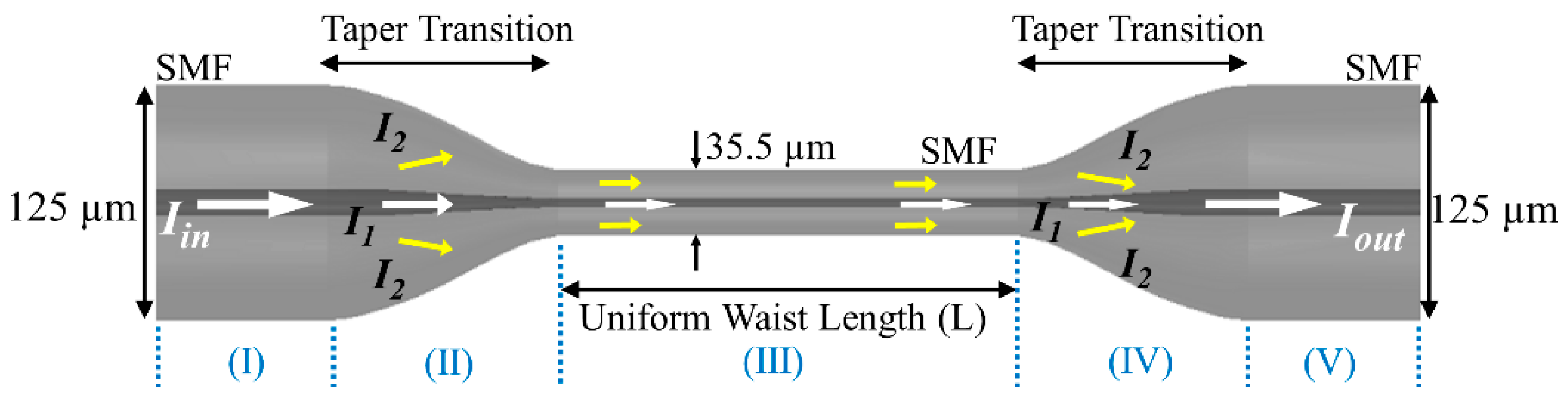
2. Principle of Sensor Operation
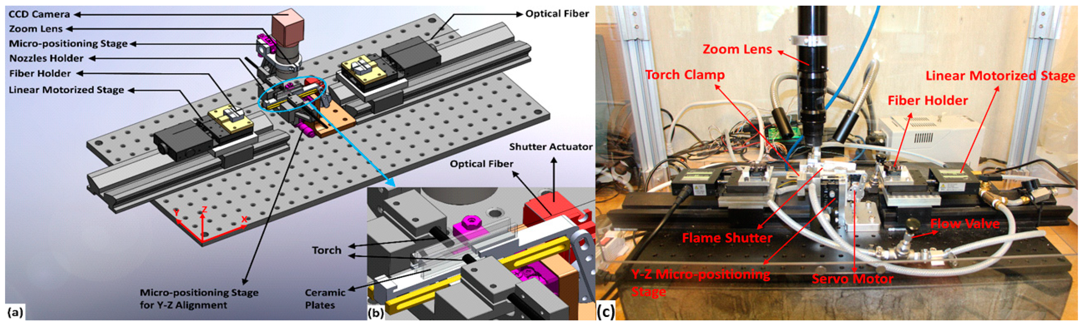
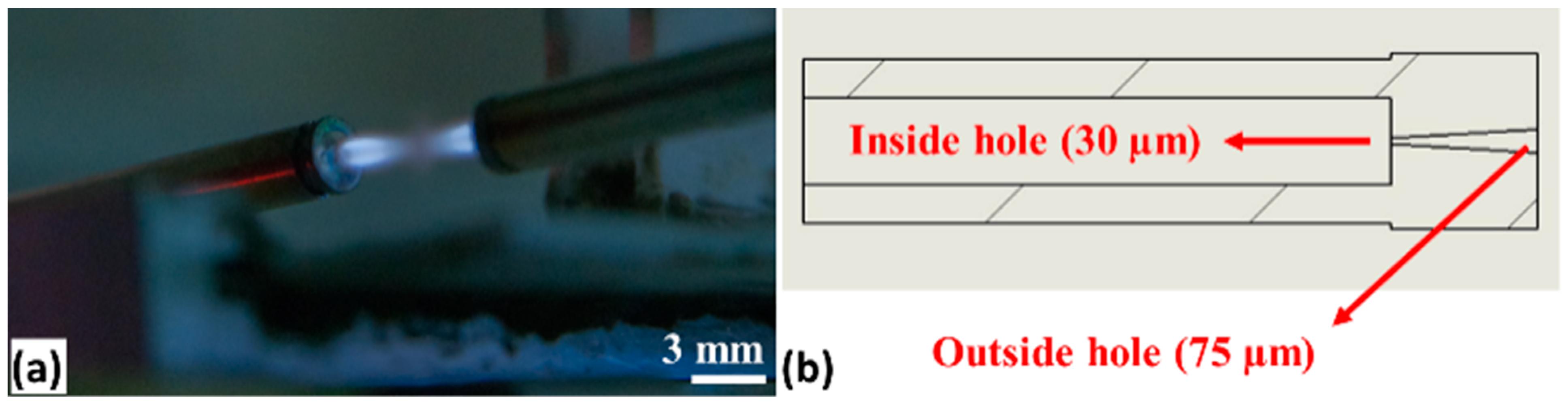
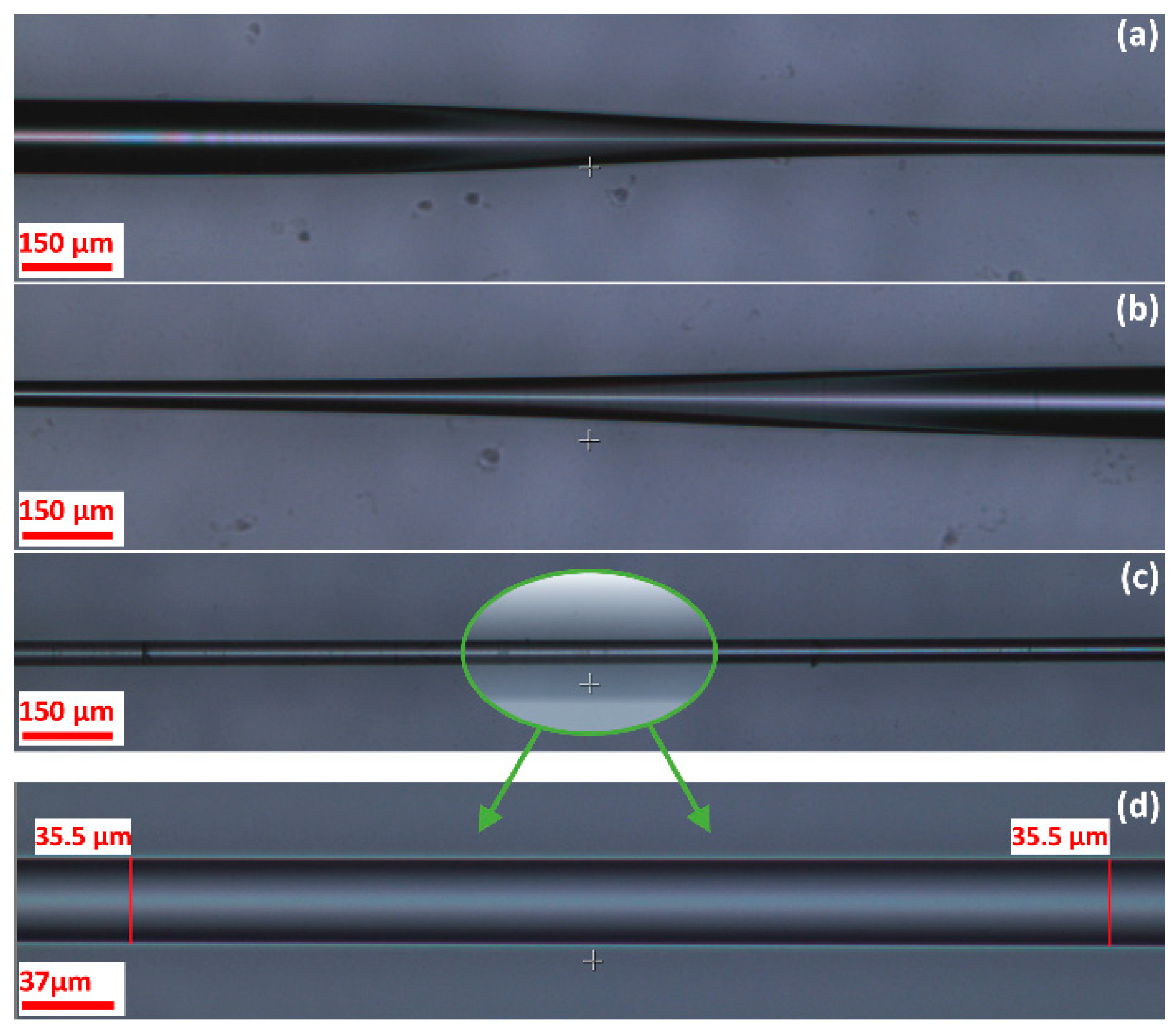
3. Sensor Fabrication
4. Results and Discussion
5. Conclusions
Author Contributions
Funding
Acknowledgments
Conflicts of Interest
References
- Wang, X.-d.; Wolfbeis, O.S. Fiber-Optic Chemical Sensors and Biosensors (2013–2015). Anal. Chem. 2016, 88, 203–227. [Google Scholar] [CrossRef] [PubMed]
- Wu, D.; Zhu, T.; Deng, M.; Duan, D.-W.; Shi, L.-L.; Yao, J.; Rao, Y.-J. Refractive index sensing based on Mach–Zehnder interferometer formed by three cascaded single-mode fiber tapers. Appl. Opt. 2011, 50, 1548–1553. [Google Scholar] [CrossRef] [PubMed]
- Shao, M.; Qiao, X.; Fu, H.; Liu, Y.; Zhao, X.; Yao, N. High sensitivity refractive index sensing of Mach–Zehnder interferometer based on multimode fiber core sandwiched between two waist-enlarged fiber tapers. Opt. Commun. 2013, 311, 359–363. [Google Scholar] [CrossRef]
- Monzón-Hernández, D.; Villatoro, J. High-resolution refractive index sensing by means of a multiple-peak surface plasmon resonance optical fiber sensor. Sens. Actuators B 2006, 115, 227–231. [Google Scholar] [CrossRef]
- Li, L.; Xia, L.; Xie, Z.; Hao, L.; Shuai, B.; Liu, D. In-line fiber Mach–Zehnder interferometer for simultaneous measurement of refractive index and temperature based on thinned fiber. Sens. Actuators A 2012, 180, 19–24. [Google Scholar] [CrossRef]
- Wang, H.; Meng, H.; Xiong, R.; Wang, Q.; Huang, B.; Zhang, X.; Yu, W.; Tan, C.; Huang, X. Simultaneous measurement of refractive index and temperature based on asymmetric structures modal interference. Opt. Commun. 2016, 364, 191–194. [Google Scholar] [CrossRef]
- Ni, K.; Dong, X.; Chan, C.C.; Li, T.; Hu, L.; Qian, W. Miniature refractometer based on Mach–Zehnder interferometer with waist-enlarged fusion bitaper. Opt. Commun. 2013, 292, 84–86. [Google Scholar] [CrossRef]
- Tian, Z.; Yam, S.S.H.; Loock, H.-P. Single-Mode Fiber Refractive Index Sensor Based on Core-Offset Attenuators. IEEE Photonics Technol. Lett. 2008, 20, 1387–1389. [Google Scholar] [CrossRef]
- Xu, Y.; Lu, P.; Chen, L.; Bao, X. Recent Developments in Micro-Structured Fiber Optic Sensors. Fibers 2017, 5, 3. [Google Scholar] [CrossRef]
- Joo-Nyung, J.; Se Yoon, K.; Sun-Wook, K.; Min-Sung, K. Temperature insensitive long-period fibre gratings. Electron. Lett. 1999, 35, 2134–2136. [Google Scholar] [CrossRef]
- Li, B.; Jiang, L.; Wang, S.; Tsai, H.-L.; Xiao, H. Femtosecond laser fabrication of long period fiber gratings and applications in refractive index sensing. Opt. Laser Technol. 2011, 43, 1420–1423. [Google Scholar] [CrossRef]
- Smietana, M.; Korwin-Pawlowski, M.L.; Bock, W.J.; Pickrell, G.R.; Szmidt, J. Refractive index sensing of fiber optic long-period grating structures coated with a plasma deposited diamond-like carbon thin film. Meas. Sci. Technol. 2008, 19, 085301. [Google Scholar] [CrossRef]
- Ahmed, F.; Joe, H.-E.; Min, B.-K.; Jun, M.B.G. Characterization of refractive index change and fabrication of long period gratings in pure silica fiber by femtosecond laser radiation. Opt. Laser Technol. 2015, 74, 119–124. [Google Scholar] [CrossRef]
- Ahsani, V.; Amin-Naseri, M.; Knickerbocker, S.; Sharma, A. Quantitative analysis of probe data characteristics: Coverage, speed bias and congestion detection precision. J. Intell. Transp. Syst. 2019, 23, 103–119. [Google Scholar] [CrossRef]
- Lee, B.H.; Kim, Y.H.; Park, K.S.; Eom, J.B.; Kim, M.J.; Rho, B.S.; Choi, H.Y. Interferometric fiber optic sensors. Sensors 2012, 12, 2467–2486. [Google Scholar] [CrossRef]
- Wo, J.; Wang, G.; Cui, Y.; Sun, Q.; Liang, R.; Shum, P.P.; Liu, D. Refractive index sensor using microfiber-based Mach–Zehnder interferometer. Opt. Lett. 2012, 37, 67–69. [Google Scholar] [CrossRef]
- Ahmed, F.; Ahsani, V.; Melo, L.; Wild, P.; Jun, M.B.-G. Miniaturized Tapered Photonic Crystal Fiber Mach-Zehnder Interferometer for Enhanced Refractive Index Sensing. IEEE Sens. J. 2016, 16, 8761–8766. [Google Scholar] [CrossRef]
- Viet Nguyen, L.; Hwang, D.; Moon, S.; Seung Moon, D.; Chung, Y. High temperature fiber sensor with high sensitivity based on core diameter mismatch. Opt. Express 2008, 16, 11369–11375. [Google Scholar] [CrossRef]
- Talataisong, W.; Wang, D.N.; Chitaree, R.; Liao, C.R.; Wang, C. Fiber in-line Mach–Zehnder interferometer based on an inner air-cavity for high-pressure sensing. Opt. Lett. 2015, 40, 1220–1222. [Google Scholar] [CrossRef] [PubMed]
- Sierra-Hernandez, J.M.; Castillo-Guzman, A.; Selvas-Aguilar, R.; Vargas-Rodriguez, E.; Gallegos-Arellano, E.; Guzman-Chavez, D.A.; Estudillo-Ayala, J.M.; Jauregui-Vazquez, D.; Rojas-Laguna, R. Torsion sensing setup based on a three beam path Mach–Zehnder interferometer. Microwave Opt. Technol. Lett. 2015, 57, 1857–1860. [Google Scholar] [CrossRef]
- Bao, Y.; Huang, Y.; Hoehler, M.S.; Chen, G. Review of Fiber Optic Sensors for Structural Fire Engineering. Sensors 2019, 19, 877. [Google Scholar] [CrossRef]
- Fu, H.; Li, H.; Shao, M.; Zhao, N.; Liu, Y.; Li, Y.; Yan, X.; Liu, Q. TCF-MMF-TCF fiber structure based interferometer for refractive index sensing. Opt. Lasers Eng. 2015, 69, 58–61. [Google Scholar] [CrossRef]
- Ahmed, F.; Ahsani, V.; Saad, A.; Jun, M.B.G. Bragg Grating Embedded in Mach-Zehnder Interferometer for Refractive Index and Temperature Sensing. IEEE Photonics Technol. Lett. 2016, 28, 1968–1971. [Google Scholar] [CrossRef]
- Zhao, Y.; Wu, D.; Wang, Q. All-fiber Mach-Zehnder interferometer using a tapered photonic crystal fiber for refractive index measurement. In Proceedings of the IEEE SENSORS 2014, Valencia, Spain, 2–5 November 2014; pp. 1080–1083. [Google Scholar]
- Grunwald, B.; Holst, G. Fibre optic refractive index microsensor based on white-light SPR excitation. Sens. Actuators A 2004, 113, 174–180. [Google Scholar] [CrossRef]
- Sharma, A.K.; Jha, R.; Gupta, B.D. Fiber-Optic Sensors Based on Surface Plasmon Resonance: A Comprehensive Review. IEEE Sens. J. 2007, 7, 1118–1129. [Google Scholar] [CrossRef]
- Rong, Q.; Qiao, X.; Wang, R.; Sun, H.; Hu, M.; Feng, Z. High-Sensitive Fiber-Optic Refractometer Based on a Core-Diameter-Mismatch Mach–Zehnder Interferometer. IEEE Sens. J. 2012, 12, 2501–2505. [Google Scholar] [CrossRef]
- Cao, Y.; Liu, H.; Tong, Z.; Yuan, S.; Su, J. Simultaneous measurement of temperature and refractive index based on a Mach–Zehnder interferometer cascaded with a fiber Bragg grating. Opt. Commun. 2015, 342, 180–183. [Google Scholar] [CrossRef]
- Chakraborty, P.; Adu-Gyamfi, Y.O.; Poddar, S.; Ahsani, V.; Sharma, A.; Sarkar, S. Traffic Congestion Detection from Camera Images using Deep Convolution Neural Networks. Transp. Res. Rec. 2018, 2672, 222–231. [Google Scholar] [CrossRef]
- Wu, D.; Zhao, Y.; Li, J. PCF taper-based Mach–Zehnder interferometer for refractive index sensing in a PDMS detection cell. Sens. Actuators B 2015, 213, 1–4. [Google Scholar] [CrossRef]
- Yin, G.; Lou, S.; Zou, H. Refractive index sensor with asymmetrical fiber Mach–Zehnder interferometer based on concatenating single-mode abrupt taper and core-offset section. Opt. Laser Technol. 2013, 45, 294–300. [Google Scholar] [CrossRef]
- Zhao, Y.; Li, X.-g.; Cai, L. A highly sensitive Mach–Zehnder interferometric refractive index sensor based on core-offset single mode fiber. Sens. Actuators A 2015, 223, 119–124. [Google Scholar] [CrossRef]
- Wang, Q.; Wei, W.; Guo, M.; Zhao, Y. Optimization of cascaded fiber tapered Mach–Zehnder interferometer and refractive index sensing technology. Sens. Actuators B 2016, 222, 159–165. [Google Scholar] [CrossRef]
- Yadav, T.K.; Narayanaswamy, R.; Abu Bakar, M.H.; Kamil, Y.M.; Mahdi, M.A. Single mode tapered fiber-optic interferometer based refractive index sensor and its application to protein sensing. Opt. Express 2014, 22, 22802–22807. [Google Scholar] [CrossRef]
- Jauregui-Vazquez, D.; Haus, J.W.; Negari, A.B.H.; Sierra-Hernandez, J.M.; Hansen, K. Bitapered fiber sensor: Signal analysis. Sens. Actuators B 2015, 218, 105–110. [Google Scholar] [CrossRef]
- Ghatak, A. Optics, 4th ed.; Tata McGraw-Hill Publishing Company Limited: New Delhi, India, 2009. [Google Scholar]
- Piao, X.; Yu, S.; Park, N. Control of Fano asymmetry in plasmon induced transparency and its application to plasmonic waveguide modulator. Opt. Express 2012, 20, 18994–18999. [Google Scholar] [CrossRef]


| Pushing Speed (µm/s) | Pushing Distance (mm) | Pulling Speed (µm/s) | Pulling Distance (mm) | Shutter Open Delay (ms) | Shutter Close Delay (ms) | TWD (µm) |
|---|---|---|---|---|---|---|
| 25 | 5 | 100 | 20 | 2000 | 0 | 62 |
| 25 | 3.5 | 140 | 19.6 | 2000 | 500 | 51.5 |
| 30 | 3 | 195 | 19.5 | 2000 | 500 | 49 |
| 25 | 2.2 | 225 | 19.6 | 2000 | 500 | 40 |
| 25 | 1.8 | 275 | 19.8 | 2000 | 500 | 35.5 |
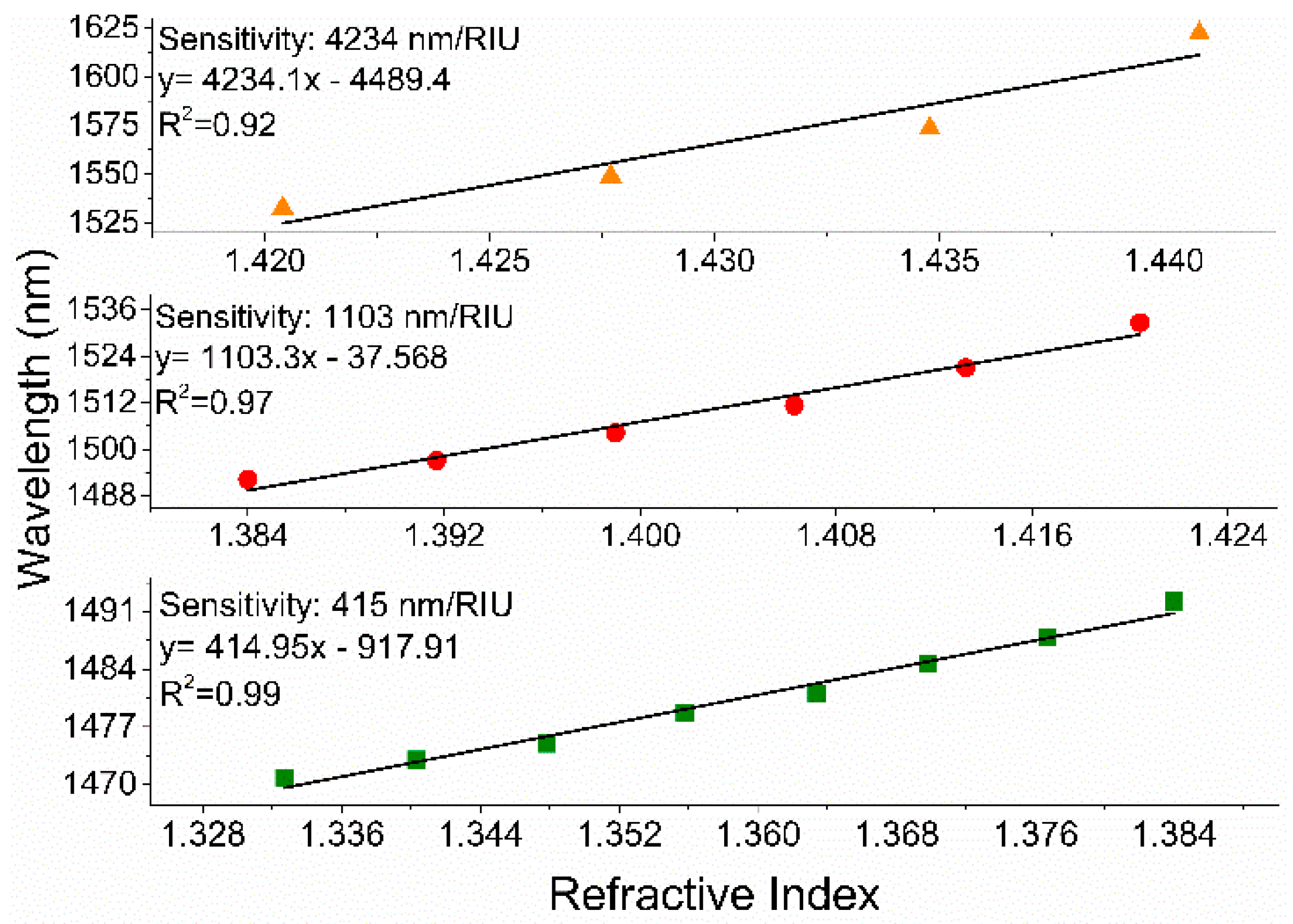
| RI Range | 1.3327 to 1.3767 | 1.3767 to 1.4063 | 1.4063 to 1.4348 | 1.3327 to 1.3840 | 1.3840 to 1.4204 | 1.4204 to 1.4408 | |
|---|---|---|---|---|---|---|---|
| TWD | |||||||
| Microfiber MZI (62 µm) | 203 nm/RIU | 290 nm/RIU | 957 nm/RIU | NA | NA | NA | |
| Microfiber MZI (49 µm) | 277 nm/RIU | 550 nm/RIU | 1520 nm/RIU | NA | NA | NA | |
| Microfiber MZI (35.5 µm) | NA | NA | NA | 415 nm/RIU | 1103 nm/RIU | 4234 nm/RIU | |
© 2019 by the authors. Licensee MDPI, Basel, Switzerland. This article is an open access article distributed under the terms and conditions of the Creative Commons Attribution (CC BY) license (http://creativecommons.org/licenses/by/4.0/).
Share and Cite
Ahsani, V.; Ahmed, F.; Jun, M.B.G.; Bradley, C. Tapered Fiber-Optic Mach-Zehnder Interferometer for Ultra-High Sensitivity Measurement of Refractive Index. Sensors 2019, 19, 1652. https://doi.org/10.3390/s19071652
Ahsani V, Ahmed F, Jun MBG, Bradley C. Tapered Fiber-Optic Mach-Zehnder Interferometer for Ultra-High Sensitivity Measurement of Refractive Index. Sensors. 2019; 19(7):1652. https://doi.org/10.3390/s19071652
Chicago/Turabian StyleAhsani, Vahid, Farid Ahmed, Martin B.G. Jun, and Colin Bradley. 2019. "Tapered Fiber-Optic Mach-Zehnder Interferometer for Ultra-High Sensitivity Measurement of Refractive Index" Sensors 19, no. 7: 1652. https://doi.org/10.3390/s19071652
APA StyleAhsani, V., Ahmed, F., Jun, M. B. G., & Bradley, C. (2019). Tapered Fiber-Optic Mach-Zehnder Interferometer for Ultra-High Sensitivity Measurement of Refractive Index. Sensors, 19(7), 1652. https://doi.org/10.3390/s19071652