An Interoperable Component-Based Architecture for Data-Driven IoT System


Abstract
1. Introduction
- System interoperability: We define system interoperability for IoT systems as the ability of the system to accommodate and support the interoperation of hardware devices with different operating systems (OS) and protocols seamlessly. Since existing IoT devices operates under diverse OS and protocols, the creation of a IoT platform architecture that is flexible to integrate with these devices is a challenge.
- Lack of flexibility in data-driven approach: The increase in data volume that is beyond possible for human effort to extract information reduces the usability of IoT systems. The data-driven approach is proven to be a solution to this issue. However, the currently available data-driven approaches lack flexibility and programmability to support the interoperation of application domains.
- A component-based IoT architecture that supports system interoperation between IoT devices with different OS: The proposed architecture treats each component as an individual service provider that operates independent of other services components. This enables the accommodation of model-based IoT systems under one architecture with only the least required interface between each system.
- The realization of flexible data-driven feedback control for IoT architecture: A proof-of-concept IoT system with the mechanism to perform data-driven automation is showcased. Furthermore, the easiness of data-driven optimization model interchange and update is demonstrated.
2. Related Work
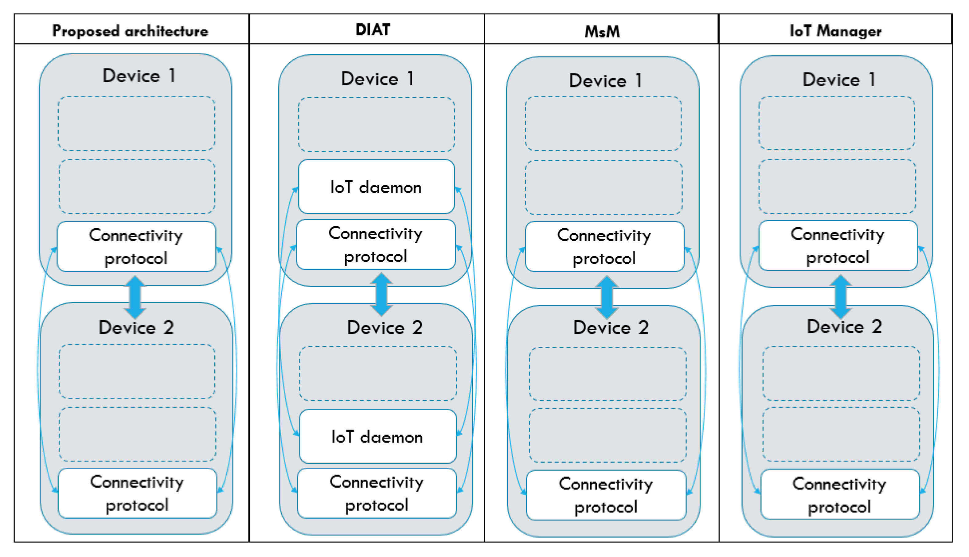
- System interoperability: The ability to accommodate devices of diverse operating systems or protocols. The system development method and choices of protocols or devices are diversified depending on application domains. As a result, this created the interoperability issue for IoT systems. To realize device interoperability, the system needs to comply with a certain standard of system architecture, such as operating systems or protocols.
- System reusability: The ability of the system to be reused for any identical or different application. The system reusability is essential for wide-scale adoption of IoT in the real world as the ease of system duplication greatly reduces the effort required to design, develop and deploy an IoT system.
- Data-driven function availability: The existence of any decision-making or action mechanism based on the data sensed. Data-driven modeling (DDM) is based on analyzing the data about a system, in particular, to find connections between the system state variables, such as input and output variables, without explicit knowledge of the physical behavior of the system [30]. The implementation could be a heuristic closed-loop feedback mechanism or machine learning and artificial intelligence techniques.
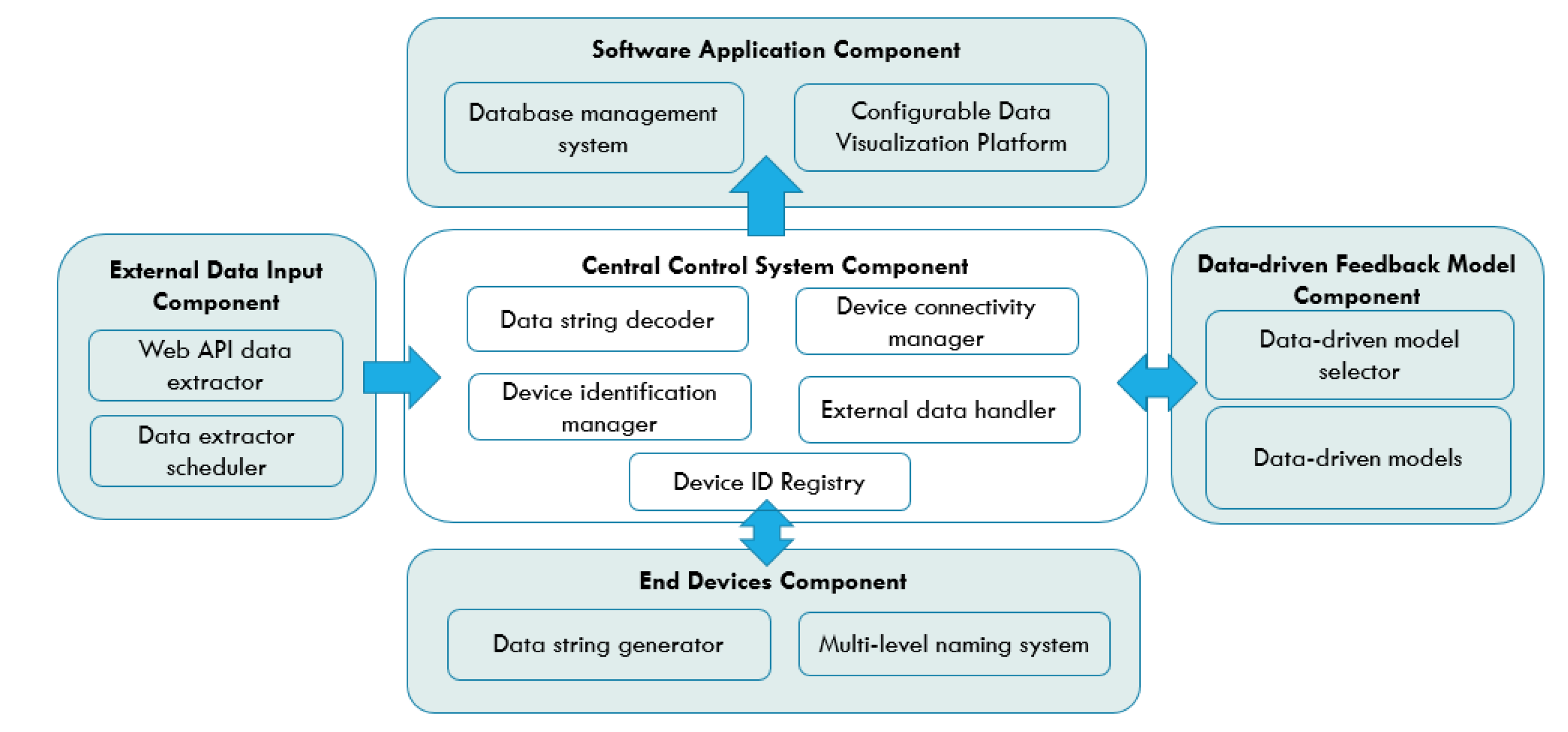
3. Component-Based IoT Architecture
3.1. Central Control System Component
- Data string decoder: Data string decoder is a sub-component that decodes the data string received from the end devices into a standard, readable-data format. A standardized data format that aggregates all the substantial values from one device is required to prevent data mismatch between devices, considering the possibility of a single device providing more than one type of data. The data format from the end devices generated by the data string generator in the end devices component is explained in the next section. Typically, the data from the end devices have to be processed into a standardized and readable format before being transferred to the data-driven feedback model component for further analysis and the database server for storage. Therefore, the data string decoder identifies the separators between essential data values in a data string and extracts the required data, which contain the sensor’s data and the device ID. The extracted data and ID are then be sent to the device identification manager for identification and classification.
- Device identification manager: This is the sub-component that identifies and classifies the ID and sensors’ data of the end devices and matches them with their corresponding actions. Firstly, the sub-component fetches the device ID from the data string decoder and tries to find a match in the existing device ID registry. If a match is found, the data under the device ID are transferred to the data-driven model selector for further action and also to their corresponding database for data storage simultaneously. The function also automatically creates a new ID for a device if the device ID is not to be found in the repository. The identification of devices is based on their multi-level device ID which enables the segregation of data from the application level down to the device level. The detail explanation of the multi-level naming system for end devices is covered in the next section.
- Device connectivity manager: This sub-component handles the connectivity and traffics between each component. The most important function of this sub-component is to maintain the parallel and simultaneous data transmission of end devices and external data sources, with the central control system component. This is to ensure that the data from each end device do not have to wait for their turns to be read. Moreover, the sub-component also ensures that the central control system component only reads a new data string from the end device when the feedback generated by the data-driven model from the previous inbound data has been successfully sent to the corresponding end device. This is to make sure that the feedback signal received by each end device is the feedback generated from the data that they have provided during the last iteration. The interface and communication of this component with the other components are achieved through general, open-sourced protocols: API call and MQTT. Specifically, the usage of MQTT protocols on top of Wi-Fi TCP/IP is suitable for the end device communications as MQTT requires only one single IP address for all the devices connected under the same gateway. This is appealing for the large-scale deployment of this architecture as it can accommodate a larger network of devices. By leveraging the edge devices as a gateway connecting multiple end devices, the end devices are able to exchange data and interact through the single IP address of the edge gateway that they are connected to. In addition, the MQTT protocol’s multi-level topic assignment is suitable for the implementation of the multi-level naming system. The topic and message structure of the MQTT protocol enables devices to receive data only from the designated party(s) based on the topic and level of subscription.
- External data handler: This sub-component is in-charge of passing the data from the external data input component to the software application components for visualization and data storage. The main functions include external data source identification, database creation, and sensor data logging.
- Device ID registry: The device ID registry is a data registry that stores all the IDs of sensors and external data sources that have previously been processed by the system. To effectively support multiple applications under one IoT system, the registry stores the device IDs and external data sources according to their applications and data types. It is used by the device identification manager to cross-reference against the incoming device ID from the end device component. The data of this registry are stored within the database of the system, together with all the sensors and external data for instant referencing.
3.2. End Devices Component
- Data string generator: The data string generator is a function that aggregates the data from a single sensor into a standardized data string format. The sensor data collected are concatenated into one string message to ensure the data from the same device is transferred and process exactly at the same time. We define the string format of the data from the end devices to be as follows: “Data 1/Data 2/…”, with solidus (/) sign as the separators of each reading. This is especially useful during the transmission of time-sensitive sensor values, as it reduces the possibility of data mismatch when more than one time-based data are transmitted at the same time. As most microcontrollers operate under different frequency and clockwise, the data sensing operation of more than one sensor under one sensor node will create a time discrepancy between different sensors, depending on which sensor is programmed to sense or read first.
- Multi-level naming system: The multi-level naming system for the end devices under this component is used for the end device ID creation. To support device interoperation, the devices and data should be well segregated despite being stored and processed under the same server. The naming of end devices begins with the categorization based on application domain followed by the services provided by them: “APPLICATION/SERVICE/#”, where “#” represents the number order of devices. An example is: “E_HEALTH/TEMPERATURE/1”. The ID of the end devices is designed to be readable for easy identification and modification. The level definition of each naming of information is essential for data labeling, especially when the node device provides more than one type of sensor readings.
3.3. Data-driven Feedback Model Component
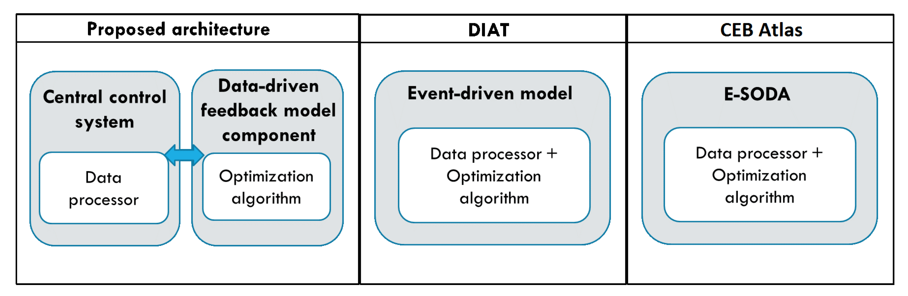
- Data-driven models: This sub-component stores all the data-driven models. The component is built as an entirely independent component to ensure the changes in the models will never affect the operations of other components. Furthermore, since both the data-driven models in this sub-component and the data from the central control system component are declared as global variables, they can be shared across different application domains or optimization models for more comprehensive optimization results. For instance, a linear regression model can be used to predict future household electricity consumption, water consumption and other applications under one unified system. Similarly, the data input of a solar irradiance sensor used for solar intensity prediction can be used by the weather prediction model or any application that makes the variable call. In short, these models can be utilized in more than one application and data can be processed by more than one data-driven models to provide higher system flexibility and interoperability.
- Data-driven model selector: This sub-component is an automated model selector and assigner for the end devices. Users can conduct performance evaluations on each algorithm, under the same, specific model or situation. Through the evaluation, users can sort out the optimum algorithm and rank the performance of different models tested under the same parameters. In addition, practitioners can also validate and test newly developed optimization or prediction models under the deployed system, which provides a realistic environment for model validation. Algorithm 1 describes the data-driven selection mechanism of the data-driven model selector. The algorithm first extracts the device ID into deviceID and sensor value into sensorValue from the in-feed data of each end device. After that, based on the preset data-driven model assigned to each deviceID, the data are processed and feedback is generated to update the operating parameter of the end device. The generated feedback is then stored in the database for reference and performance comparison other models used by the same deviceID previously. If there is no model from the modelList pre-assigned to the deviceID, the data are processed by the first model in the modelList until convergence and all the generated feedback data are stored to the database. During the next iteration of optimization, the second model is used to generate feedback until convergence and this continues until all the models in the modelList are used. The stored data of all the models are compared against each other to select the model with the best optimization performance for that specific deviceID. Lastly, the model id assigned to the deviceID for future feedback generations.
| Algorithm 1 Data-Driven Model Selector |
| 1: for each end device do |
| 2: extract |
| 3: extract |
| 4: for each i∈[0, length()−1] do |
| 5: if = [i] then |
| 6: |
| 7: generate feedback |
| 8: else if = [i] then |
| 9: |
| 10: generate feedback |
| 11: else |
| 12: |
| 13: generate feedback |
| 14: end if |
| 15: update operating parameter of end device with feedback |
| 16: store feedback in database |
| 17: end for |
| 18: end for |
3.4. External Data Input Component
- Web API data extractor: A web API data extractor is a sub-component to curl the data from any designated API. It also includes decode of the data downloaded through web API into JSON format through a curl script.
- API data extractor scheduler: The API data extractor scheduler is a function that automatically repeats the data extraction process by a fixed interval set by the user to receive the latest data from the API data provider.
3.5. Software Application Component
- Configurable data visualization platform: The configurable data visualization platform is a data visualization web application and graphical user interface (GUI) for data monitoring panel controls. To enable system interoperation under one platform and reusable for different application, the data visualization module provides a modifiable data presentation platform to suit the requirement of multiple application domains. Furthermore, considering the wide adaption and usage of Business Intelligence (BI) data analytic tools such as Microsoft’s Power BI and SAP Business Intelligence, customizable and flexible data visualization platform is useful for a more comprehensive data presentations. However, it is also crucial to reduce the complexity of data pre-processes to increase the platform’s usability. Therefore, this component aims to maximize the customizability of the data visualization platform and to minimize the requirement of complicated data pre-processes by providing a customizable and flexible data visualization platform that can directly interface with the databases of the IoT systems.
- Database management system: The database management system is a generic database system with an essential feature: automatic database generation for new incoming data. The central control system identifies the databases and data-driven models for incoming data based on their device ID and determine whether the database for the data from this device has already been created.
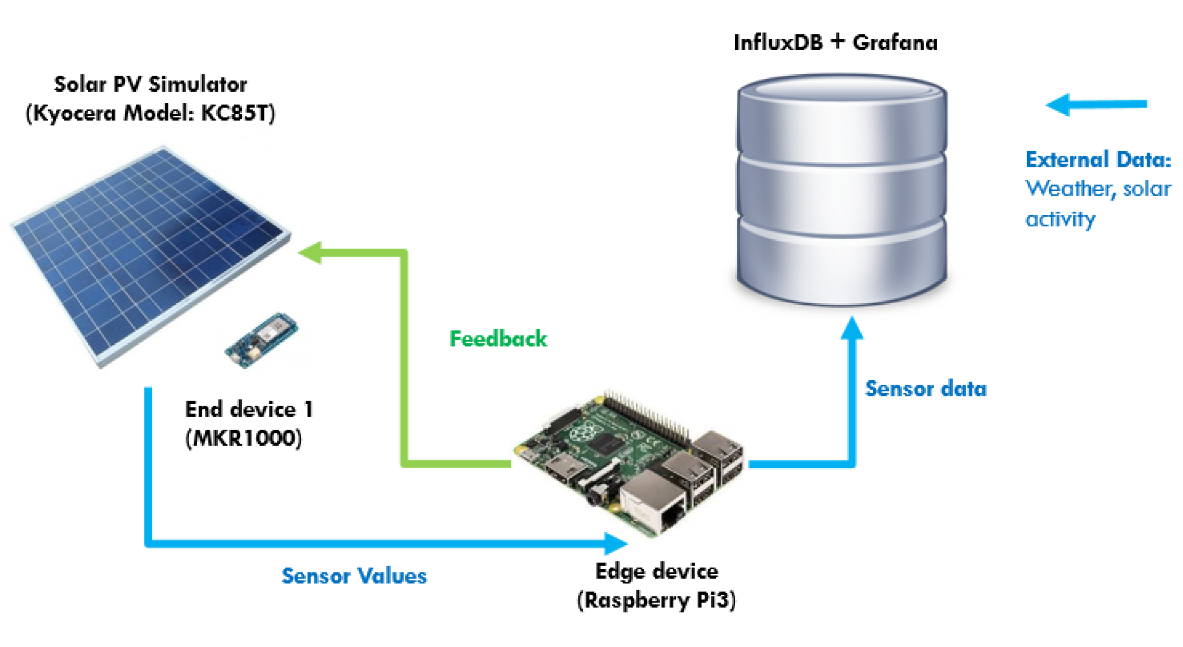
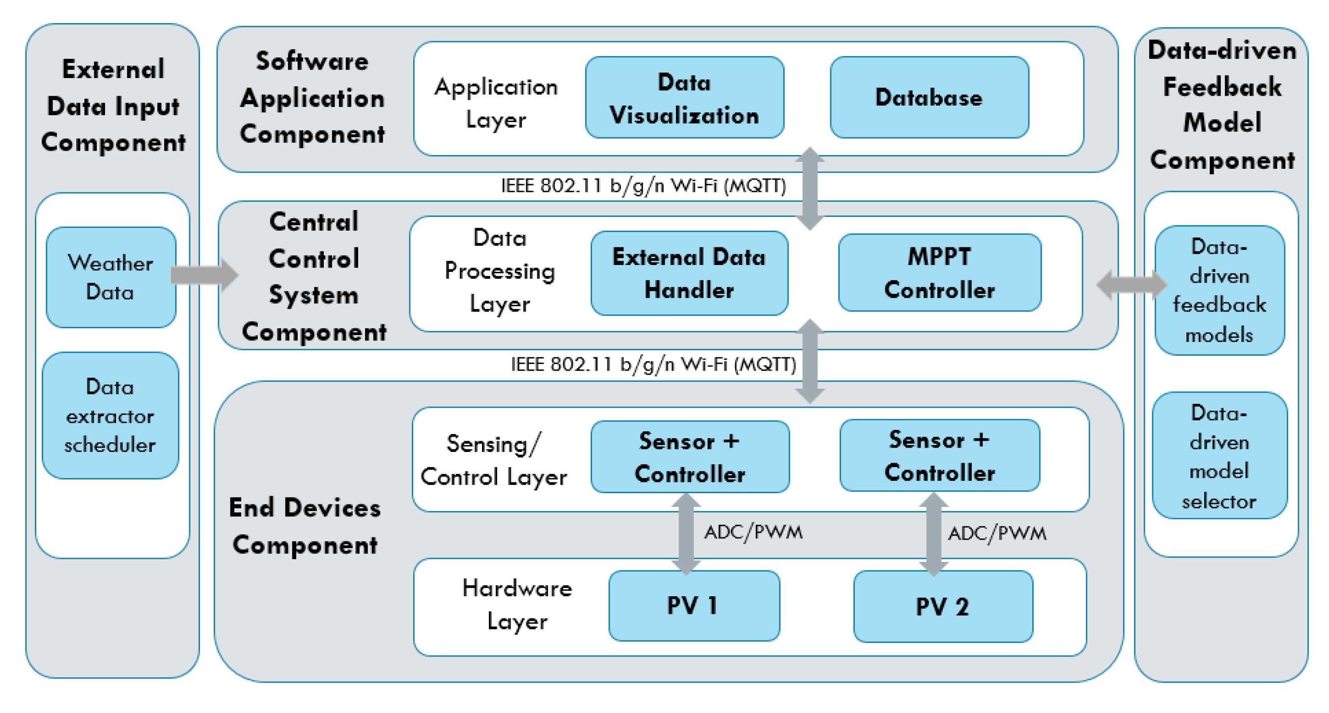
4. Use Case and Implementation
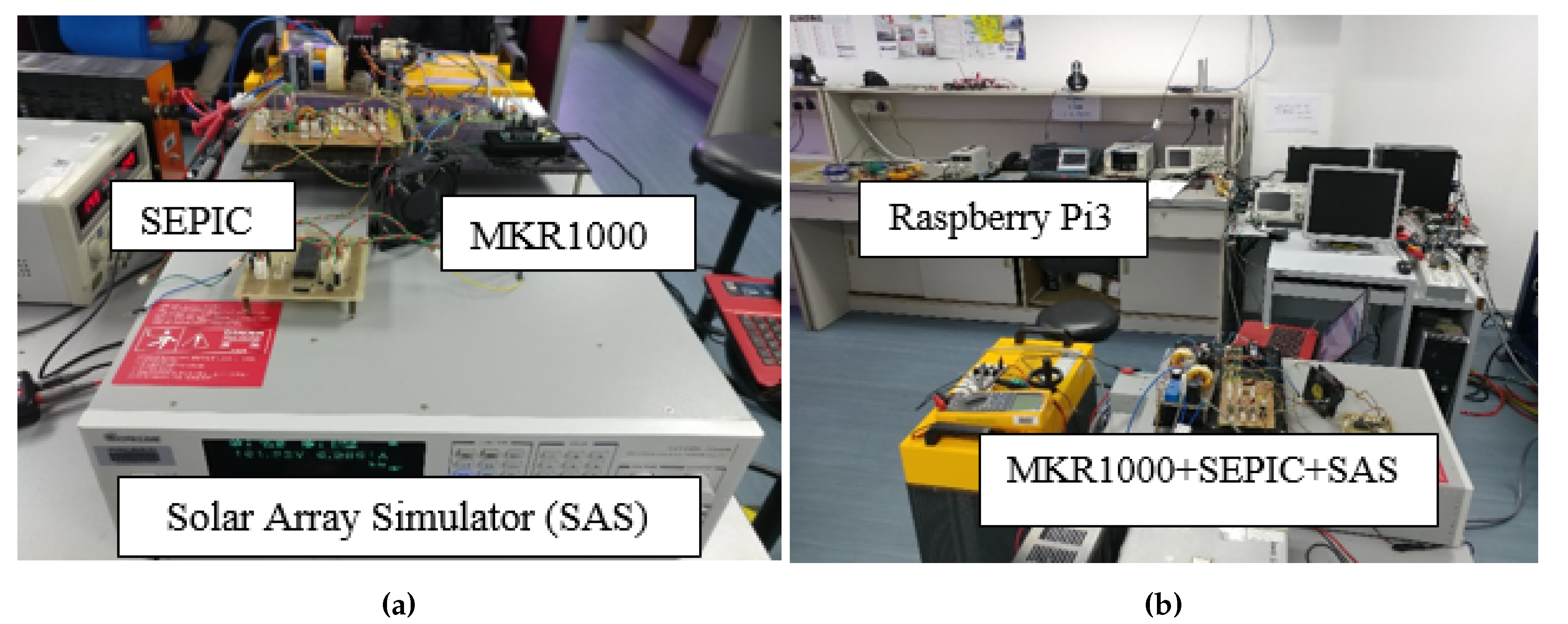
4.1. Use Case: Solar PV Maximum Power Point Tracker (MPPT)
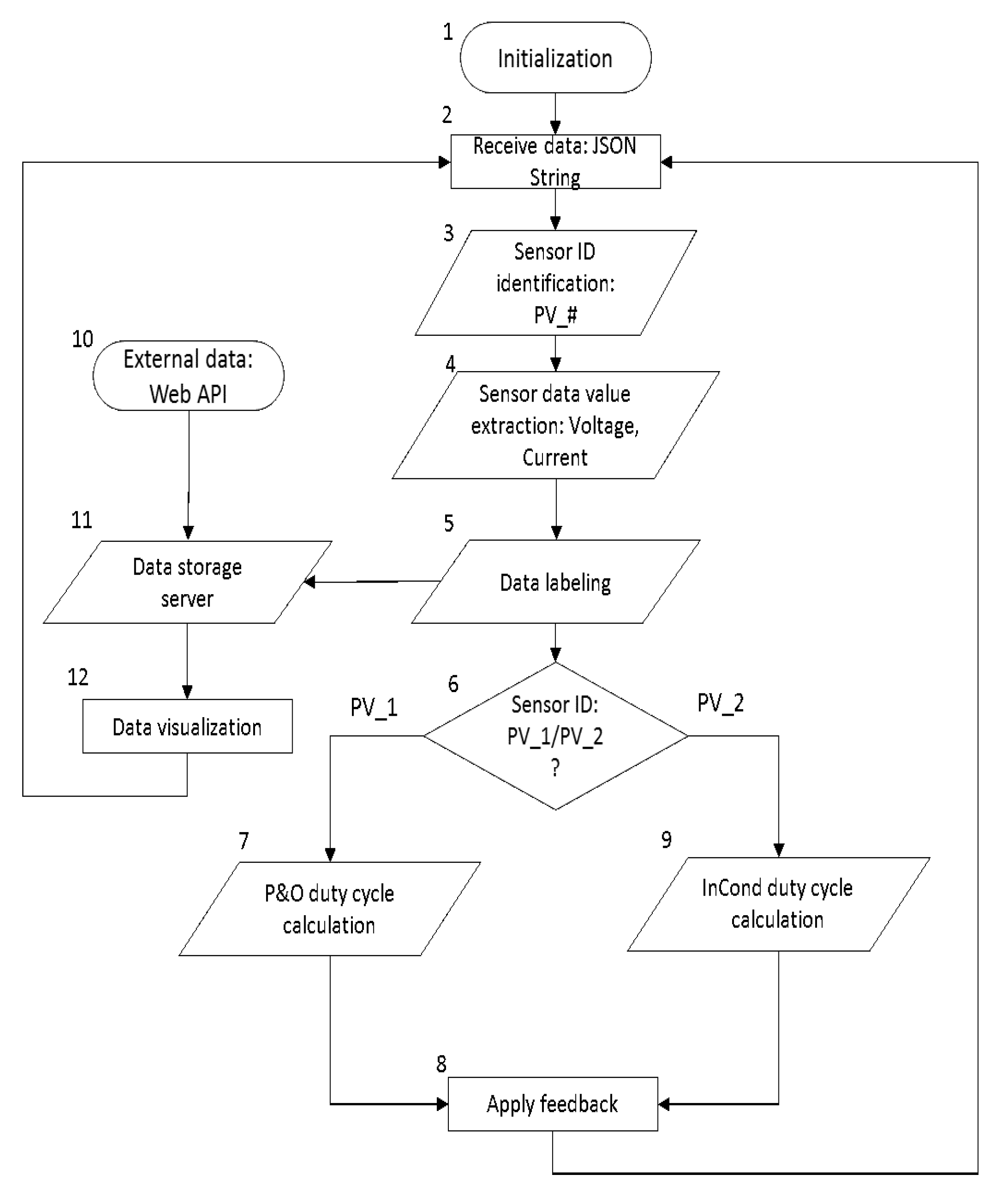
4.2. Implementation
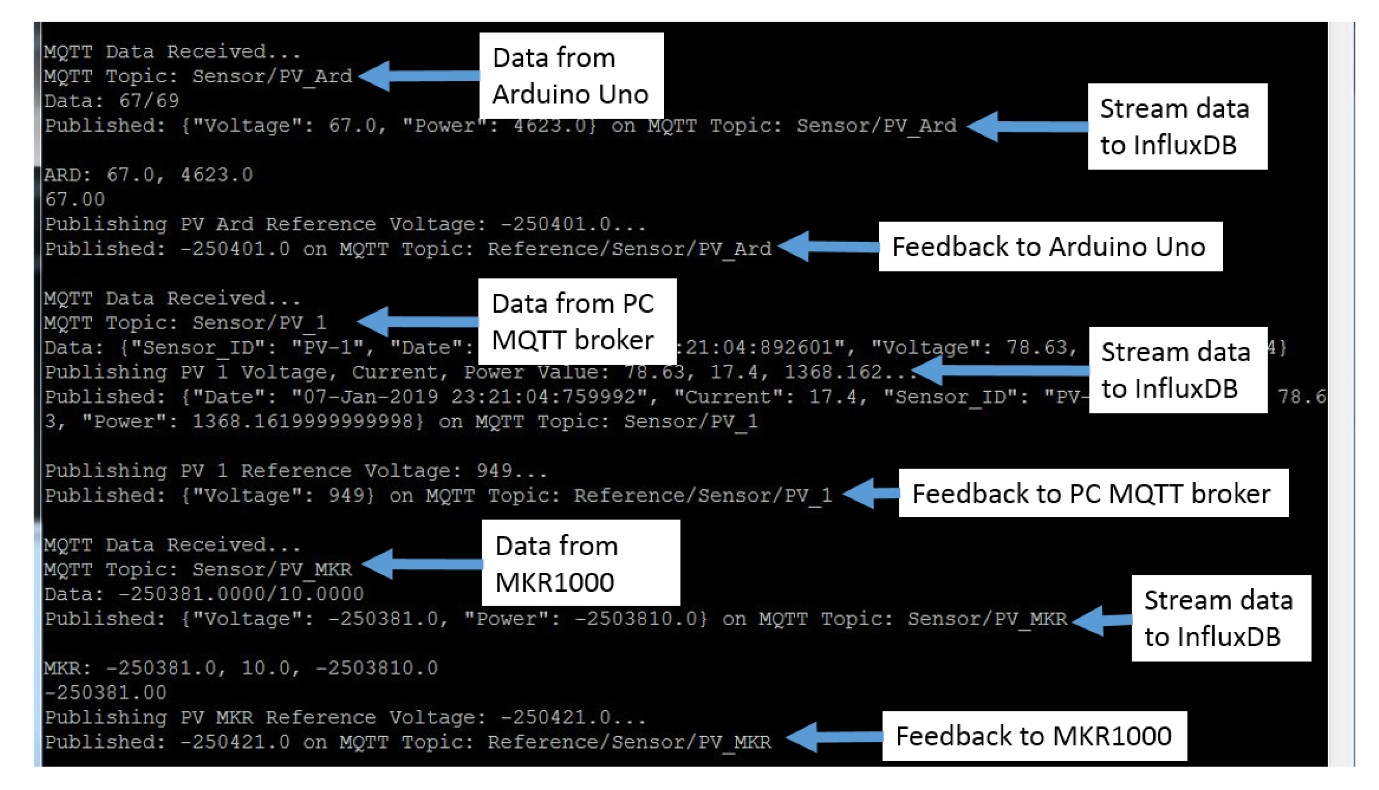
- Data Processing Function: Firstly, the system receives data from the voltage and current sensors, and the sensor IDs are identified through the topic of the MQTT messages. After that, the message, which is in the format “Voltage/Current”, is decoded to extract voltage and current values. The extracted data are then labeled according to their respective device ID and are assigned to the corresponding data-driven feedback model. For instance, the voltage and current data with device ID “PV_#” are assigned to their respective MPPT data-driven feedback model for feedback generation.
- Data-driven model: The data-driven model generates feedback through the MPPT algorithms: Perturb and Observe (P&O) and Incremental Conductance (InCond). Users can select or update the algorithms without the need to manually reassign the data to the newly-selected model or to change the data input format, as the data-driven models react to the same set of input data. Furthermore, under the same data-driven model, the assignment of the different algorithm can be done. For instance, user can assign P&O algorithm for PV_1 and InCond algorithm for PV_2, and vice versa. After going through the MPPT calculation, the feedback signals are transmitted back to the end devices to be applied on the solar PV’s DC-DC converter to update the controller’s action. The program then continues its iteration to read the next data set to decide the upcoming feedback action.
- External data input handler: The external data input handler is in charge of data curling from any website on the Internet through API. For our use case, we import external weather data from the OpenWeatherMap as a reference. The OpenWeatherMap is an online service that provides weather data, such as daily weather forecast and historical data. The data provided are available in JSON format and accessible through free API. However, only certain data (current weather data and five-day/3-h forecast) are available for free. For experiment purpose, we only collected these data, stored them in InfluxDB on a daily basis, and visualized the data on Grafana.
5. Experiment Results and Discussions
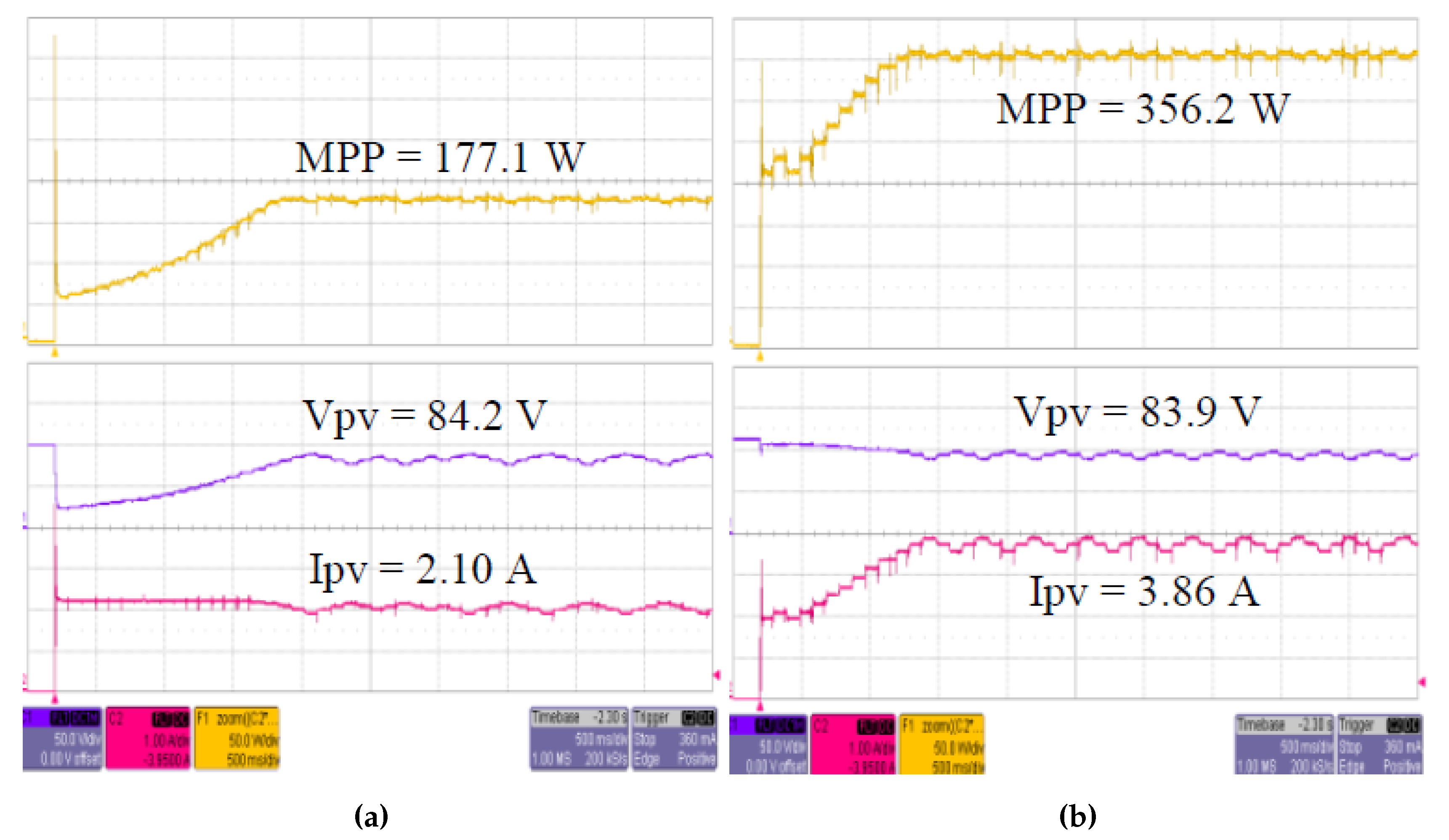
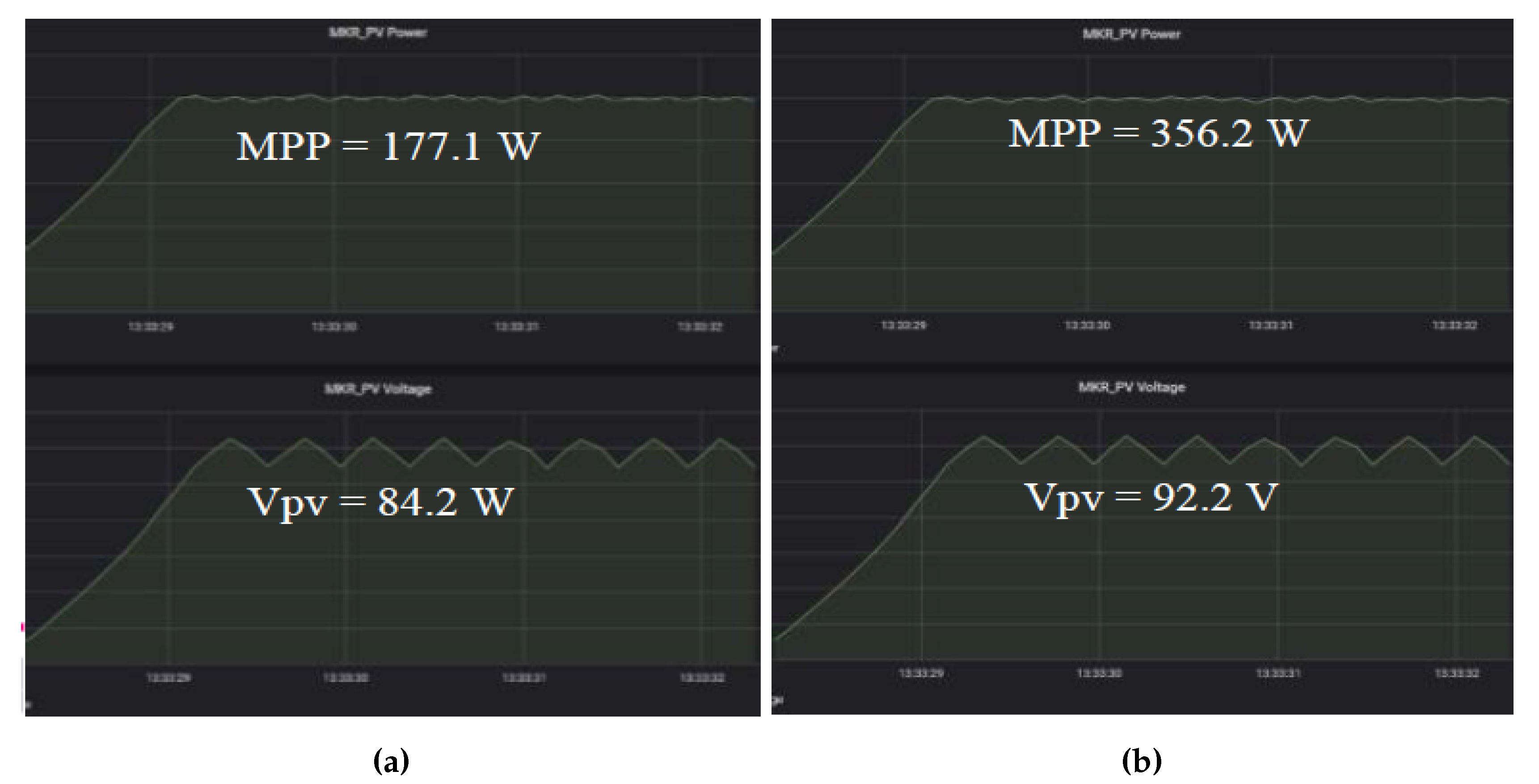
5.1. MPPT Implementation Experiment
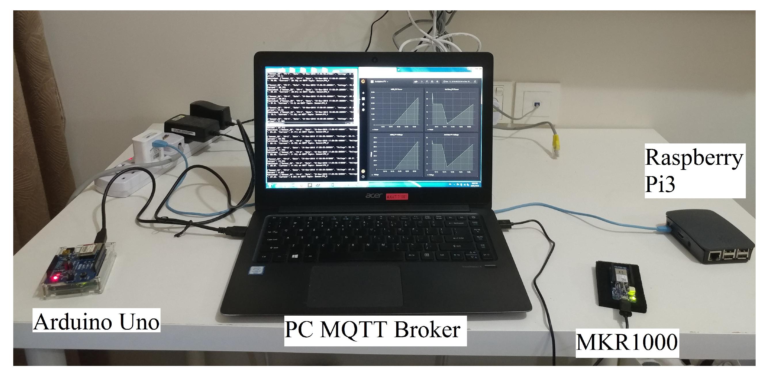
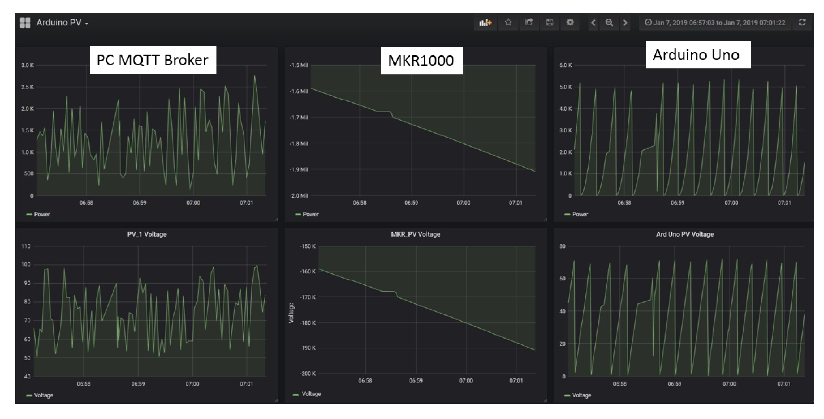
5.2. System Interoperation Experiment
5.3. Discussions
5.4. System Interoperability
5.5. The Flexibility of Data-Driven Function
5.6. Potential Application Domains and Use-Cases
- Smart factory: Smart factory systems generally interact with a large network of sensors and controllers that requires real-time data sensing and feedback action. Furthermore, these end devices are typically operating under diverse protocols such as RFID, Modbus, and MQTT.
- Household smart grid: Household smart grid typically manages both the supply and demand of electricity of a household. The supply-side consists of the electricity from the national grid and any electricity generated from renewable energy, whereas the demand-side consists of the appliances that consume electricity. In short, a household smart grid system is required to manage sensors and relays of both supply and demand-side, which are two different systems integrated on one platform. For instance, a smart grid system is deemed to provide instant adjustment on household electricity generation during high solar irradiance; or electricity consumption during on/off-peak period throughout the day, or when the user is not within the premise.
- Smart city: Smart city systems are combinations of multiple IoT applications including smart grids, smart traffic systems, and smart home systems with highly condense network of sensors, CCTVs, and controllers. In fact, the smart city is one of the most ideal use cases that is suitable to be implemented using the proposed architecture due to its cross-domain integration and high-density data volume that requires data-driven feedback models.
6. Conclusions
Author Contributions
Funding
Acknowledgments
Conflicts of Interest
References
- Smallbon, V.; Potie, T.; D’Souza, M.; Postula, A.; Ros, M. Implementation of radio tomographic imaging based localisation using a 6LoWPAN wireless sensor network. In Proceedings of the 2015 12th International Joint Conference on e-Business and Telecommunications (ICETE), Colmar, France, 20–22 July 2015; Volume 6, pp. 27–32. [Google Scholar]
- Ravidas, S.; Lekidis, A.; Paci, F.; Zannone, N. Access control in Internet-of-Things: A survey. J. Comput. Appl. Technol. 2019, 144, 79–101. [Google Scholar] [CrossRef]
- Muelen, R. Gartner Says 8.4 Billion Connected “Things” Will Be in Use in 2017, Up 31 Percent From 2016. Available online: https://www.gartner.com/en/newsroom/press-releases/2017-02-07-gartner-says-8-billion-connected-things-will-be-in-use-in-2017-up-31-percent-from-2016 (accessed on 10 October 2018).
- Aloi, G.; Caliciuri, G.; Fortino, G.; Gravina, R.; Pasquale, P.; Russo, W.; Savaglio, C. Enabling IoT interoperability through opportunistic smartphone-based mobile gateways. J. Comput. Appl. Technol. 2016, 81. [Google Scholar] [CrossRef]
- Li, J.; Jin, J.; Yuan, D.; Zhang, H. Virtual Fog: A Virtualization Enabled Fog Computing Framework for Internet of Things. IEEE Internet Things J. 2018, 5, 121–131. [Google Scholar] [CrossRef]
- Al-Fuqaha, A.; Guizani, M.; Mohammadi, M.; Aledhari, M.; Ayyash, M. Internet of Things: A Survey on Enabling Technologies, Protocols, and Applications. IEEE Commun. Surv. Tutorials 2015, 17, 2347–2376. [Google Scholar] [CrossRef]
- Chen, I.; Guo, J.; Bao, F. Trust Management for SOA-Based IoT and Its Application to Service Composition. IEEE Trans. Serv. Comput. 2016, 9, 482–495. [Google Scholar] [CrossRef]
- Costa, B.; Pires, P.F.; Delicato, F.C.; Li, W.; Zomaya, A.Y. Design and Analysis of IoT Applications: A Model-Driven Approach. In Proceedings of the 2016 IEEE 14th Intl Conf on Dependable, Autonomic and Secure Computing, 14th Intl Conf on Pervasive Intelligence and Computing, 2nd Intl Conf on Big Data Intelligence and Computing and Cyber Science and Technology Congress (DASC/PiCom/DataCom/CyberSciTech), Auckland, New Zealand, 8–12 August 2016; pp. 392–399. [Google Scholar] [CrossRef]
- Konduru, V.R.; Bharamagoudra, M.R. Challenges and solutions of interoperability on IoT: How far have we come in resolving the IoT interoperability issues. In Proceedings of the 2017 International Conference On Smart Technologies For Smart Nation (SmartTechCon), Bangalore, India, 17–19 August 2017; pp. 572–576. [Google Scholar] [CrossRef]
- Boman, J.; Taylor, J.; Ngu, A.H. Flexible IoT middleware for integration of things and applications. In Proceedings of the 10th IEEE International Conference on Collaborative Computing: Networking, Applications and Worksharing, Miami, FL, USA, 22–25 October 2014; pp. 481–488. [Google Scholar] [CrossRef]
- Li, Y.; Alqahtani, A.; Solaiman, E.; Perera, C.; Jayaraman, P.P.; Buyya, R.; Morgan, G.; Ranjan, R. IoT-CANE: A unified knowledge management system for data-centric Internet of Things application systems. J. Parallel Distrib. Comput. 2019, 131, 161–172. [Google Scholar] [CrossRef]
- Guimarães, C.; Quevedo, J.; Ferreira, R.; Corujo, D.; Aguiar, R.L. Exploring interoperability assessment for Future Internet Architectures roll out. J. Network Comput. Appl. 2019, 136, 38–56. [Google Scholar] [CrossRef]
- COMPOSE Project. Collaborative Open Market to Place Objects at Your Service. Available online: http://www.compose-project.eu/ (accessed on 18 October 2018).
- Vukobratovic, D.; Jakovetic, D.; Skachek, V.; Bajovic, D.; Sejdinovic, D.; Karabulut Kurt, G.; Hollanti, C.; Fischer, I. CONDENSE: A Reconfigurable Knowledge Acquisition Architecture for Future 5G IoT. IEEE Access 2016, 4, 3360–3378. [Google Scholar] [CrossRef]
- Sarkar, C.; Nambi, S.N.; Prasad, R.V.; Rahim, A.; Neisse, R.; Baldini, G. DIAT: A Scalable Distributed Architecture for IoT. IEEE Internet Things J. 2015, 2, 230–239. [Google Scholar] [CrossRef]
- Xu, Y.; Helal, A. Scalable Cloud-Sensor Architecture for the Internet of Things. IEEE Internet Things J. 2016, 3, 285–298. [Google Scholar] [CrossRef]
- Banafa, A. Three Major Challenges Facing IoT. 2017. Available online: https://iot.ieee.org/newsletter/march-2017/three-major-challenges-facing-iot.html (accessed on 18 October 2018).
- Calderoni, L.; Magnani, A.; Maio, D. IoT Manager: An open-source IoT framework for smart cities. J. Syst. Archit. 2019. [Google Scholar] [CrossRef]
- Balasubramanian, V.; Zaman, F.; Aloqaily, M.; Ridhawi, I.A.; Jararweh, Y.; Salameh, H.B. A Mobility Management Architecture for Seamless Delivery of 5G-IoT Services. In Proceedings of the ICC 2019-2019 IEEE International Conference on Communications (ICC), Shanghai, China, 20–24 May 2019; pp. 1–7. [Google Scholar] [CrossRef]
- ur Rehman, M.H.; Liew, C.S.; Wah, T.Y.; Khan, M.K. Towards next-generation heterogeneous mobile data stream mining applications: Opportunities, challenges, and future research directions. J. Network Comput. Appl. 2017, 79, 1–24. [Google Scholar] [CrossRef]
- Tsai, C.; Lai, C.; Chiang, M.; Yang, L.T. Data Mining for Internet of Things: A Survey. IEEE Commun. Surv. Tutor. 2014, 16, 77–97. [Google Scholar] [CrossRef]
- Borthakur, D.; Gray, J.; Sarma, J.S.; Muthukkaruppan, K.; Spiegelberg, N.; Kuang, H.; Ranganathan, K.; Molkov, D.; Menon, A.; Rash, S.; et al. Apache Hadoop Goes Realtime at Facebook; ACM: New York, NY, USA, 2011; pp. 1071–1080. [Google Scholar] [CrossRef]
- Mukherjee, A.; Paul, H.S.; Dey, S.; Banerjee, A. ANGELS for distributed analytics in IoT. In Proceedings of the 2014 IEEE World Forum on Internet of Things (WF-IoT), Seoul, Korea, 6–8 March 2014; pp. 565–570. [Google Scholar] [CrossRef]
- Araujo, V.; Mitra, K.; Saguna, S.; Åhlund, C. Performance evaluation of FIWARE: A cloud-based IoT platform for smart cities. J. Parallel Distrib. Comput. 2019. [Google Scholar] [CrossRef]
- Alelaiwi, A. Evaluating distributed IoT databases for edge/cloud platforms using the analytic hierarchy process. J. Parallel Distrib. Comput. 2019, 124, 41–46. [Google Scholar] [CrossRef]
- Xing, J.; Dai, H.; Yu, Z. A distributed multi-level model with dynamic replacement for the storage of smart edge computing. J. Syst. Archit. 2018, 83, 1–11. [Google Scholar] [CrossRef]
- Cao, H.; Wachowicz, M. An Edge-Fog-Cloud Architecture of Streaming Analytics for Internet of Things Applications. Sensors 2019, 19, 3594. [Google Scholar] [CrossRef]
- Ma, M.; Wang, P.; Chu, C. Data Management for Internet of Things: Challenges, Approaches and Opportunities. In Proceedings of the 2013 IEEE International Conference on Green Computing and Communications and IEEE Internet of Things and IEEE Cyber, Physical and Social Computing, Beijing, China, 20–23 August 2013; pp. 1144–1151. [Google Scholar] [CrossRef]
- Stack, T. Cisco Survey Reveals Close to Three-Fourths of IoT Projects Are Failing. 2017. Available online: https://newsroom.cisco.com/press-release-content?articleId=1847422 (accessed on 18 October 2018).
- Solomatine, D.; See, L.; Abrahart, R. Data-Driven Modelling: Concepts, Approaches and Experiences. In Practical Hydroinformatics: Computational Intelligence and Technological Developments in Water Applications; Abrahart, R.J., See, L.M., Solomatine, D.P., Eds.; Springer: Berlin/Heidelberg, Germany, 2008; pp. 17–30. [Google Scholar] [CrossRef]
- Balasubramanian, V.; Kouvelas, N.; Chandra, K.; Prasad, R.V.; Voyiatzis, A.G.; Liu, W. A unified architecture for integrating energy harvesting IoT devices with the Mobile Edge Cloud. In Proceedings of the 2018 IEEE 4th World Forum on Internet of Things (WF-IoT), Singapore, 5–8 February 2018; pp. 13–18. [Google Scholar] [CrossRef]
- Benayache, A.; Bilami, A.; Barkat, S.; Lorenz, P.; Taleb, H. MsM: A microservice middleware for smart WSN-based IoT application. J. Network Comput. Appl. 2019, 144, 138–154. [Google Scholar] [CrossRef]
- Predescu, A.; Mocanu, M.; Lupu, C. Real time implementation of IoT structure for pumping stations in a water distribution system. In Proceedings of the 2017 21st International Conference on System Theory, Control and Computing (ICSTCC), Sinaia, Romania, 19–21 October 2017; pp. 529–534. [Google Scholar] [CrossRef]
- Al-Ali, A.R.; Zualkernan, I.A.; Rashid, M.; Gupta, R.; Alikarar, M. A smart home energy management system using IoT and big data analytics approach. IEEE Trans. Consum. Electron. 2017, 63, 426–434. [Google Scholar] [CrossRef]
- Habib ur Rehman, M.; Jayaraman, P.P.; Malik, S.U.R.; Khan, A.U.R.; Medhat Gaber, M. RedEdge: A Novel Architecture for Big Data Processing in Mobile Edge Computing Environments. J. Sens. Actuator Networks 2017, 6, 17. [Google Scholar] [CrossRef]
- Tey, K.S.; Mekhilef, S.; Seyedmahmoudian, M.; Horan, B.; Oo, A.T.; Stojcevski, A. Improved Differential Evolution-Based MPPT Algorithm Using SEPIC for PV Systems Under Partial Shading Conditions and Load Variation. IEEE Trans. Ind. Inf. 2018, 14, 4322–4333. [Google Scholar] [CrossRef]
- Logeswaran, T.; SenthilKumar, A. A Review of Maximum Power Point Tracking Algorithms for Photovoltaic Systems under Uniform and Non-uniform Irradiances. Energy Procedia 2014, 54, 228–235. [Google Scholar] [CrossRef]
- Esram, T.; Chapman, P.L. Comparison of Photovoltaic Array Maximum Power Point Tracking Techniques. IEEE Trans. Energy Convers. 2007, 22, 439–449. [Google Scholar] [CrossRef]
- InfluxDB: Purpose-Built Open Source Time Series Database. Available online: https://www.influxdata.com/products/influxdb-overview/ (accessed on 23 October 2018).
- Grafana—The Open Platform for Analytics and Monitoring. Available online: https://grafana.com/ (accessed on 23 October 2018).
- Montori, F.; Bedogni, L.; Bononi, L. A Collaborative Internet of Things Architecture for Smart Cities and Environmental Monitoring. IEEE Internet Things J. 2018, 5, 592–605. [Google Scholar] [CrossRef]
- Konecný, J.; McMahan, H.B.; Ramage, D.; Richtárik, P. Federated Optimization: Distributed Machine Learning for On-Device Intelligence. arXiv 2016, arXiv:1610.02527. [Google Scholar]
- Abadi, M.; Agarwal, A.; Barham, P.; Brevdo, E.; Chen, Z.; Citro, C.; Corrado, G.S.; Davis, A.; Dean, J.; Devin, M.; et al. TensorFlow: Large-Scale Machine Learning on Heterogeneous Distributed Systems. arXiv 2016, arXiv:1603.04467. [Google Scholar]


| Data-driven Function | System | System | |
|---|---|---|---|
| Availability | Interoperability | Reusability | |
| DIAT [15] | Yes | No | Yes |
| Condense [14] | No | No | Yes |
| Atlas CEB [16] | Yes | No | Yes |
| Predescu’s model [33] | Yes | No | No |
| Al-Ali’s model [34] | No | No | No |
| 2EA [31] | Yes | No | No |
| FIFu [12] | No | No | No |
| MsM [32] | No | Yes | Yes |
| IoT-CANE [11] | No | No | No |
| IoT Manager [18] | No | Yes | Yes |
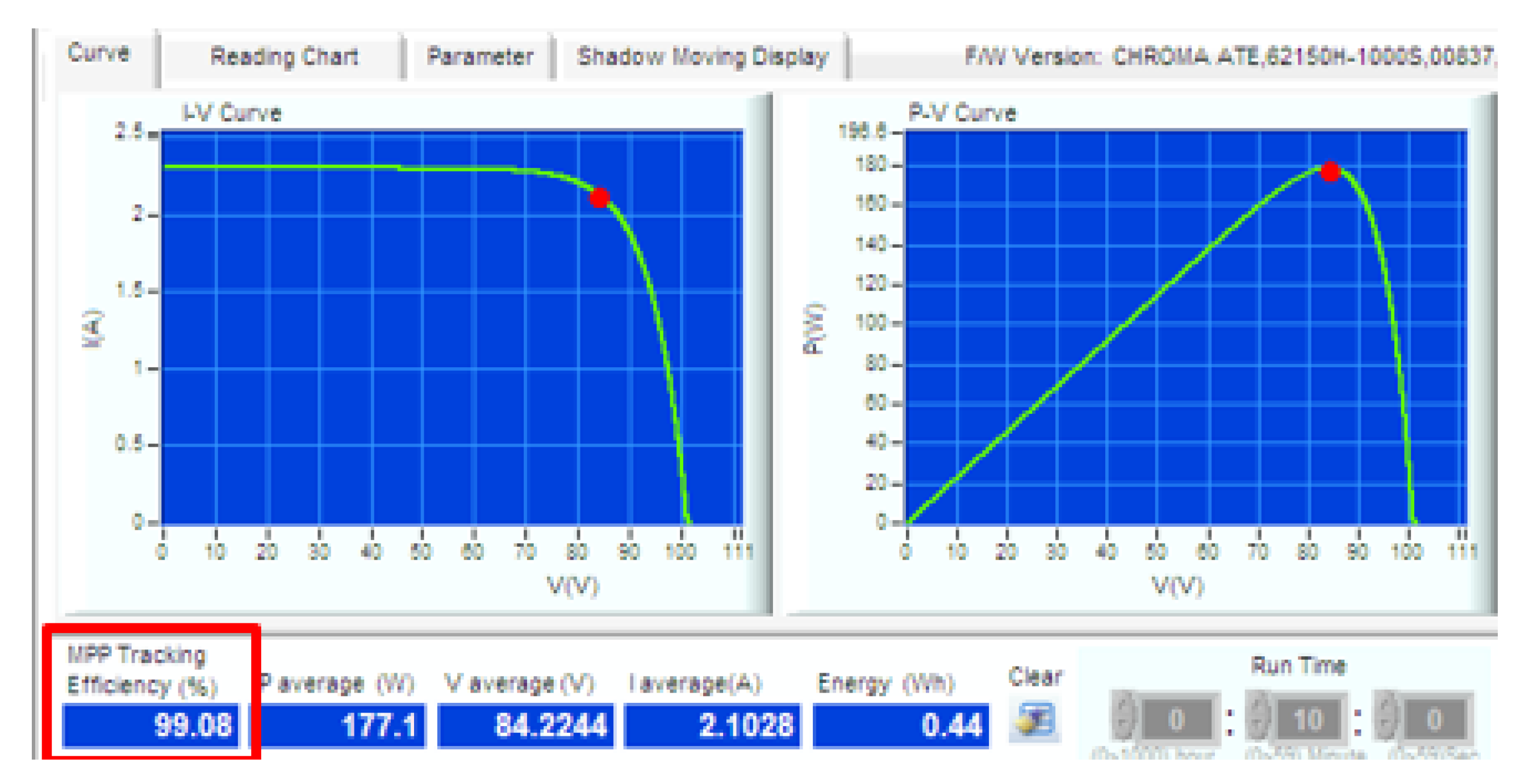
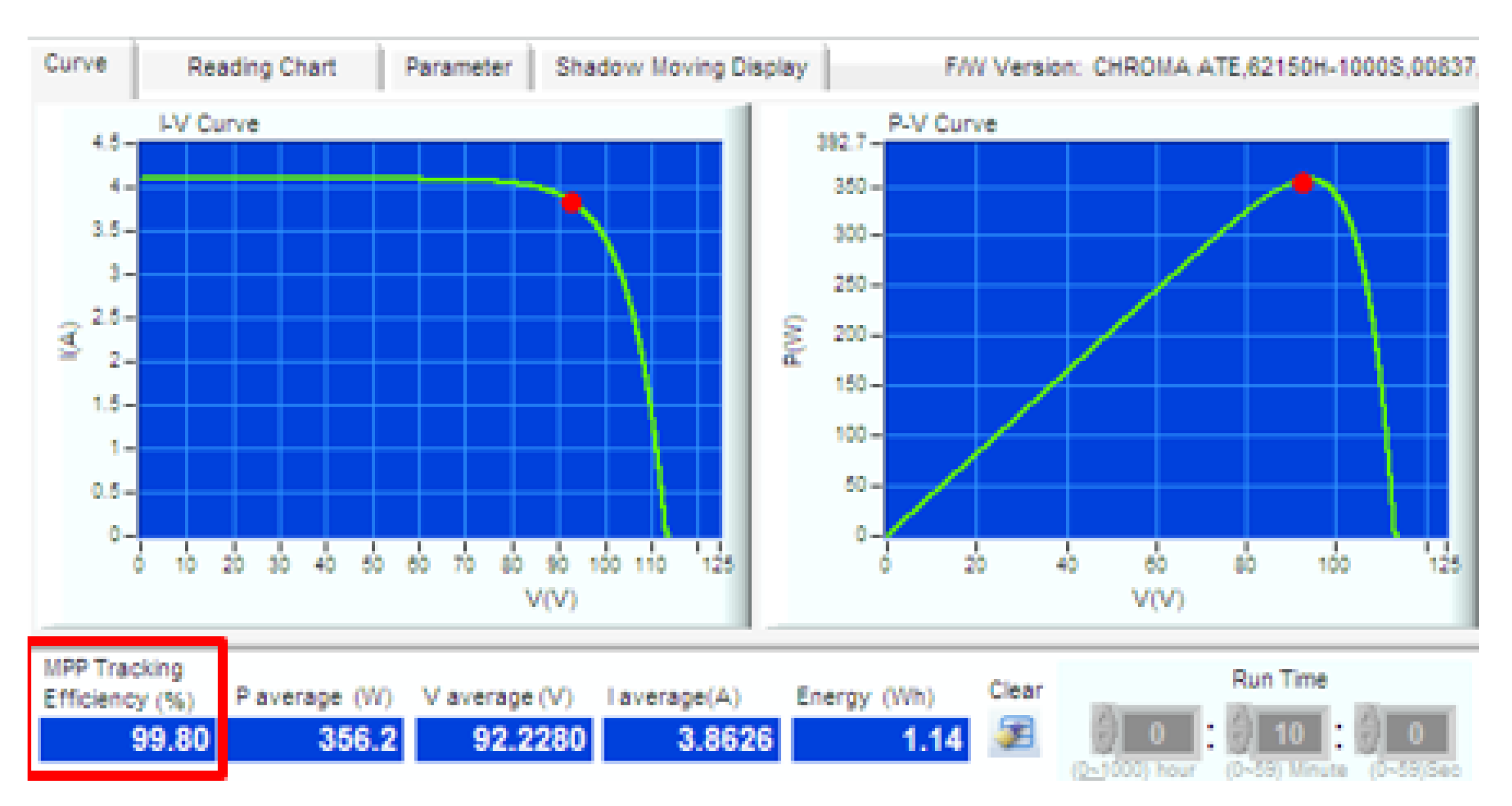
| Solar PV Isolation | 344 W/m | 667 W/m |
| Voltage at MPP (Vmpp) | 83.9 V | 93.8 V |
| Current at MPP (Impp) | 2.13 A | 3.81 A |
| Open circuit Voltage (Voc) | 101.2 V | 113.2 V |
| Short circuit Current (Isc) | 2.29 A | 4.10 A |
© 2019 by the authors. Licensee MDPI, Basel, Switzerland. This article is an open access article distributed under the terms and conditions of the Creative Commons Attribution (CC BY) license (http://creativecommons.org/licenses/by/4.0/).
Share and Cite
Lo, S.K.; Liew, C.S.; Tey, K.S.; Mekhilef, S. An Interoperable Component-Based Architecture for Data-Driven IoT System. Sensors 2019, 19, 4354. https://doi.org/10.3390/s19204354
Lo SK, Liew CS, Tey KS, Mekhilef S. An Interoperable Component-Based Architecture for Data-Driven IoT System. Sensors. 2019; 19(20):4354. https://doi.org/10.3390/s19204354
Chicago/Turabian StyleLo, Sin Kit, Chee Sun Liew, Kok Soon Tey, and Saad Mekhilef. 2019. "An Interoperable Component-Based Architecture for Data-Driven IoT System" Sensors 19, no. 20: 4354. https://doi.org/10.3390/s19204354
APA StyleLo, S. K., Liew, C. S., Tey, K. S., & Mekhilef, S. (2019). An Interoperable Component-Based Architecture for Data-Driven IoT System. Sensors, 19(20), 4354. https://doi.org/10.3390/s19204354