1. Introduction
For a long time, there has been a well-acknowledged need to promote the learning of subjects related to science, technology, engineering and mathematics (the so-called STEM areas) to high-school students. The term STEM has recently been extended with an
A for
arts [
1,
2], which may involve humanities, language, dance, drama, music, visual arts, design, new media, and—why not?—also
martial arts. One of the goals behind STEAM is to teach students innovation, critical thinking and the use of engineering/technology-related concepts/processes in imaginative designs. Other goals of the STEAM ecosystem involve the development of creative approaches and solutions applicable to real-world problems that build on top of the students’ former mathematical/scientific backgrounds [
3].
In this paper, we argue that aikido (a defensive martial art based on circular motions and
close-to-elastic scattering), in combination with simple movement monitoring sensors (i.e., inertial sensors) and visual tracking devices (e.g., simple video cameras, depth recovering gadgets, etc.) can provide a creative way of teaching important concepts related to one of the exponents of the STEM domain: physics. An
intelligent computing framework capable of registering (both in time and in a 3D Cartesian space) the information of the aforementioned devices is also described in this work. We also assert that this method of transmitting knowledge can be truly understood by high-school students while they remain engaged in the rest of the STEM curricula. In this work, we mainly focus on the concept of
moment of inertia. This physical quantity (tackled in
Section 6.1) is often misunderstood and difficult to
grasp by young students [
4]. The main reason relies on the fact that this concept is addressed from a
demotivating methodological perspective based on calculations around idealistic geometrical figures (spheres, cylinders, segments rings, etc.) and their associated spinning movements around an isolated axis of rotation. This
otherworldly learning setting (at least in the physics realm) is felt by students as
unconnected to reality. In this context, we believe that the human body can also serve as a means of studying the concept of moment of inertia (among others) through a proper affordable multi-sensor and video-enriched framework. Performing movements in aikido involves applying forces, moving fluently through a 3D space (i.e., the
tatami) and transforming energy. As we look deeper into aikido, we find that this
energy state mutation should only comprise kinematics. This is well known by aikido masters with a background in science and engineering. However, the benefits of using martial arts (and especially aikido) to understand scientific concepts, and, in particular, those related to physics, have hardly been reported in literature. To the authors’ knowledge, only the works by Mroczkowski, compiled in [
5], report a scientifically validated study that shows the value of learning physics and aikido in a combined way. With this motivation, in this paper, we go beyond the aforementioned works and investigate how to support the learning of physics using sensor technology with aikido as a case study, by addressing the following research question:
Can inertial sensors and visual tracking devices enable the production of enriched learning materials that facilitate the understanding of physics ideas by showing, in a combined way, meaningful aikido techniques (performed/explained by martial artists), together with the data provided by these devices?
In order to get our own insights into this matter, we participated in two science outreach related events during the
2019 Education Week event (presented respectively in
Section 3 and
Section 5.3). Both experiences have influenced the development of an approach that we have named
Physics + Aikido, or
Phy + Aik for short. It consists in an intelligent registering framework to generate innovative educational material. In particular, the goal of
Phy + Aik is to allow students the access to curated educational material that combines synchronized visual information (high-quality videos and live exhibitions) and tagged data streams collected by inertial sensors. These time series can be produced with the involvement of physics teachers and even real aikido instructors at in situ scenarios or in pre-recorded demonstrations. In addition,
Phy + Aik can also serve to monitor the movements performed by the students when re-enacting, by themselves, the movements shown in the videos or during the live demonstrations. Such a merging of combined information can eventually contribute to help the student identify real-world forces, movements and related complex magnitudes such as
dynamic momentum,
angular momentum, and
moment of inertia. As it will be further discussed along the present text, the required equipment can be easily acquired and its complexity just lies in the registration process succinctly discussed in
Section 5.
Aside from introducing
Phy + Aik, the rest of the paper is structured as follows. In
Section 2, we comment on the background of our approach. In
Section 3, we present a user study among high-school students showing that the concept of moment of inertia is better understood by watching live demonstrations of aikido techniques. Then, in
Section 4, we introduce the equipment that can be used in
Phy + Aik to
sensorize the aikido practice. Next, in
Section 5, we present the
Phy + Aik framework to allow educators generate innovative visual educational material. Following that, in
Section 6, we review some physics concepts (including the aforementioned moment of inertia) that could be also be taught with
Phy + Aik. Finally, some conclusions and ideas for future work are outlined in
Section 7.
2. Background
As stated in [
6], the digital and physical worlds have in recent years opened new possibilities for children and adults to interact with their environment. This interaction is bidirectional: the
environment also interacts with the students. Such interaction is made mainly possible primarily by 2D bitmap displays and sensors. A sensor is nothing else but
something (generally an electronic device) that detects or measures a
physical event. It can also record such episodes/sessions to be reviewed/studied later and it can likewise warn the user in real-time and/or even automatically respond to them. A good example of this last characteristic is the fall detection capabilities of some state-of-the-art
smart watches, which are able to autonomously call emergency services in case of such an undesirable incident.
As reviewed in [
7], inertial sensors (i.e., those that are based on the concept of
inertia, such accelerometers and gyroscopes) can be used to learn motor skills, which are key in sports and martial arts. The use of sensors in the learning of sports has been widely applied. For instance, in [
8], a wearable device is attached to a swimmer in order to improve the learner’s swimming technique. In a very similar way, the authors in [
9] evaluate the wrist rotation in golf. In [
10], the authors propose a sensor-based system to monitor and assist
snowboarders. This system goes beyond the typical accelerometer-gyro tandem by adding two pressure sensors in the snowboarder’s shoes. In any case, inertial sensors have proven valuable to measure sports performance, although a particular device may be more suitable and effective than others depending on the sports application [
11].
The goal of all of these sensor-based applications is for the wearers to gain (in fact,
learn) insights about their own motion, style, state, and even the physical environment and conditions in which their practice takes (or took) place. This knowledge is usually gained
offline, that is, once the exercise has been completed, the learner can review and interpret the recorded data (video sequences and/or inertial records). In addition, the learner can go a step further and
connect this knowledge to a physical
ground truth (or theoretical basis). As a result, he/she is able to improve the performance of the physical exercise being tracked (or previously monitored) in combination with the review of the physics processes associated with it. However, in this context, we believe that not only the person carrying out the physical activity, but also external schoolmates reviewing the associated gestures and dynamics, are able to learn the physics involved. As suggested by the outcomes of the study reported in
Section 3, this way of learning turns out to be more
useful than merely studying the theoretical basis in a text book. In this way, it is possible to develop handy learning materials for STEM teaching. This approach is the one followed in
Phy + Aik, where instead of being based on the practice of more traditional sports activities, it encompasses the application of martial arts (and aikido in particular), which entails additional benefits for learning physics.
3. Case Study
As stated in
Section 1, we have carried out a user study to have our own evidence that watching movements of aikido is useful for learning some concepts of physics. Here, we report the user study we have carried out at
Feria Madrid for Science and Innovation 2019, which was held on 28–31 March 2019 in Madrid (Spain). This scientific event is tailored to high-school students with physics in their curriculum and has the aim of disseminating science in a participatory atmosphere as it is aligned with the
STEMadrid Plan focused on developing programs that strengthen the interest of teenagers in scientific and technological subjects. This year’s event took place during the
Education Week. The activity
Physics, Aikido and Artificial Intelligence was conducted during a four-hour time slot at UNED’s stand on the morning of March 28th, from 10:00 a.m. to 2:00 p.m.
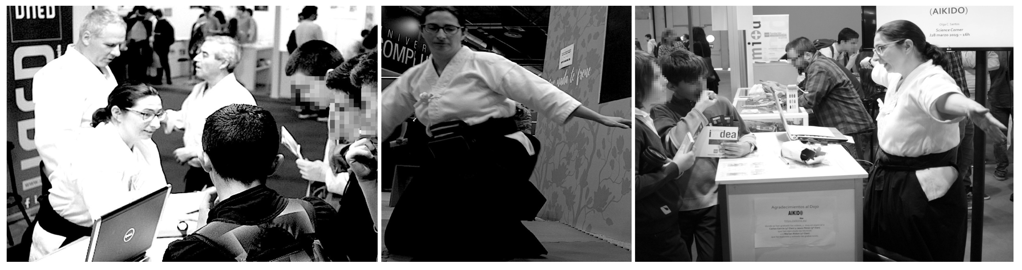
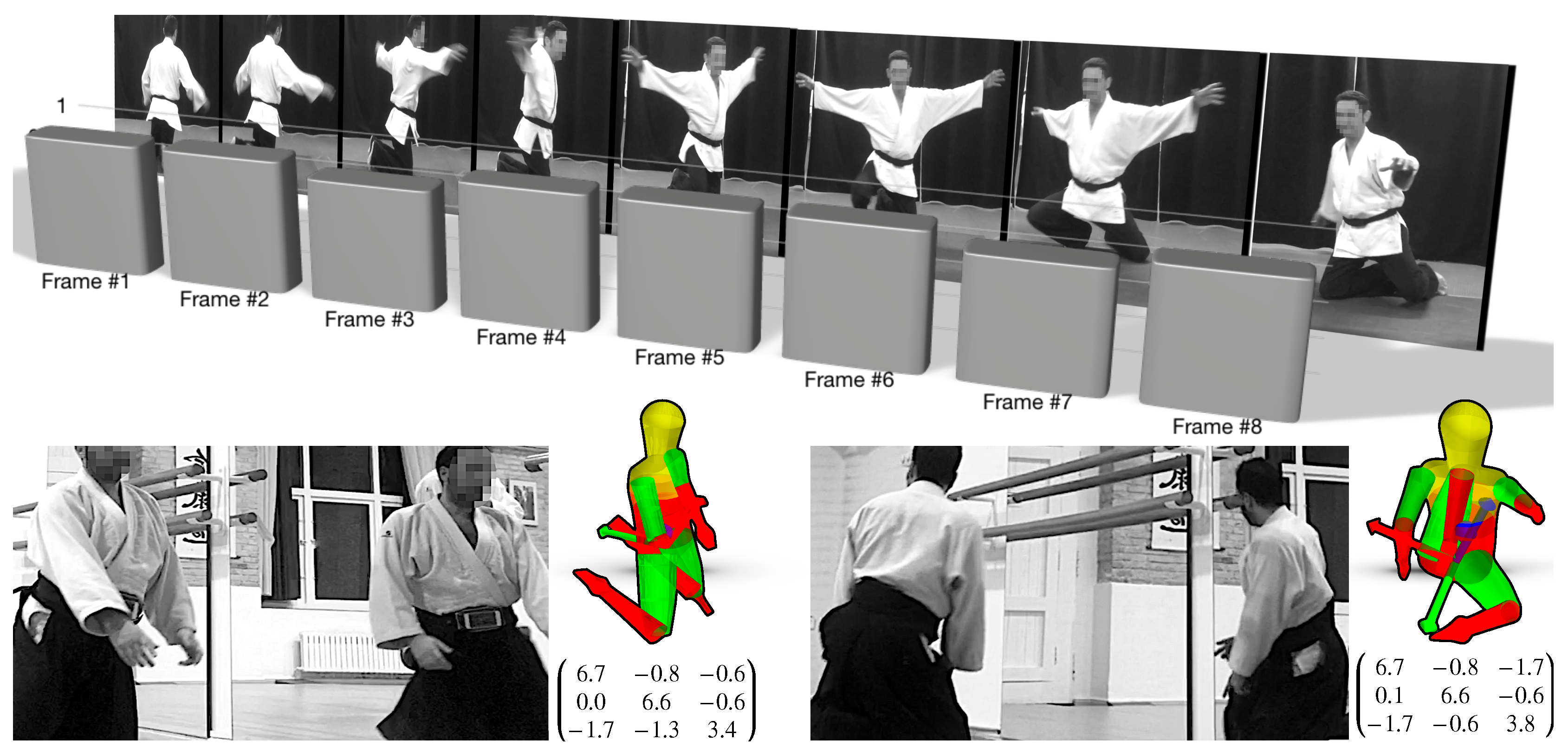
Young participants who came to the stand (see
Figure 1—left) were asked to complete a pre-test covering some concepts of physics and then watched some movements of the aikido practice performed by black belt-level practitioners of the
Aikime dojo. As detailed below, the concept of moment of inertia was demonstrated with the
shikko movement performing 180
turns (u-turns) while knee-walking, i.e., performing
suwari waza tai sabaki shikko ho (or
irimi tenkan shikko) several times (see
Figure 1—center). Then, they were asked to fill out a post-test. After that, the researcher provided some explanations to the participants (
Figure 1—right).
The
shikko exercise can be roughly compared to
walking on knees (also known as
samurai-walking).
Shikko (e.g.,
Figure 1—center) is very useful for developing awareness of one’s own centre of mass, also known as
hara in the aikido jargon. This fact contributes to being able to keep a stable position that is later needed for other stand-up techniques. In other words, it can (and effectively does) improve the practitioner’s balance even for movements outside of the
shikko practice itself. In a previous work [
13], we proposed that, through the use of inertial sensors, it is possible to model the aforementioned knee-walking movement by measuring inertial information (acceleration and angular velocity) in the
hara’s coordinate system. Motion information can be collected with a smartphone attached to the practitioner’s waist using a
fanny pack (also known as
bum bag) placed ad hoc or even carefully positioned between the skin (at the level of the navel) and the
aikidogi (the traditional Japanese garment worn by aikido practitioners). Smartphones are a very useful solution because nowadays they are
ubiquitous devices (i.e., everyone has one of those), and thus the barrier for their introduction into the classroom for STEAM teaching purposes is lower than using a dedicated device. Of course, as discussed in
Section 4, a scientific-range sensor can also be used.
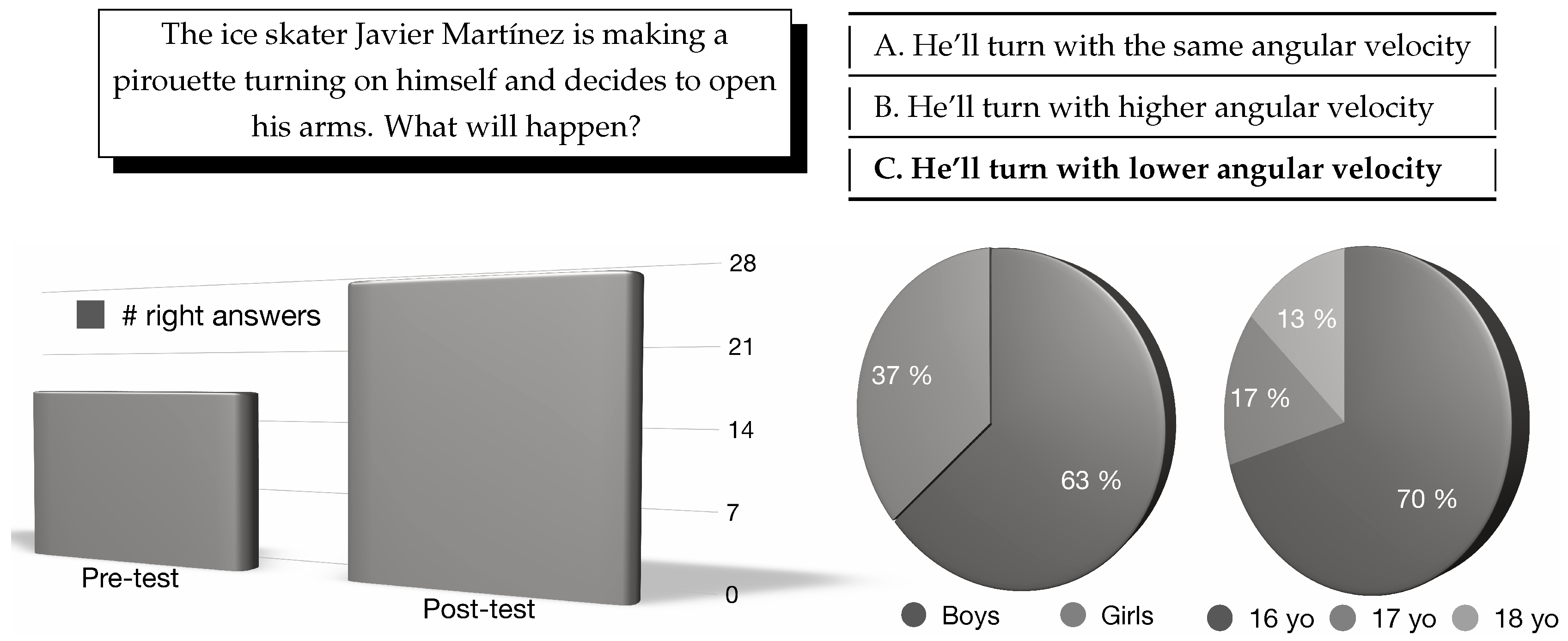
During the execution part of the activity, in some occasions the arms of the aikido practitioners remained widely opened and, in others, they stood close to the body, so that participants could perceive the effect on the speed of the turn due to the change in the body’s contour. The associated physics concept has to do with the fact that the angular momentum (
L) equals the moment of inertia (
I) multiplied by the angular velocity (
). Thus, when the aikido practitioner modifies the shape of his/her body, the moment of inertia changes (i.e.,
) because it depends on the distance of each point of the body to the turning axis, so the further the points are from each other (i.e., if the arms are open), the larger the moment of inertia is computed (
). Since the angular momentum is conserved when no external forces are applied (
), as in this case, the angular velocity has to inevitably change (i.e.,
). Specifically, with open arms, the angular velocity is reduced (
). Hence, the speed of the turn is
controllable by opening/closing the arms. All of these concepts were quickly summarized to the students after the live demonstration took place and the post-test was done (
Figure 1—right). For the sake of completeness, these ideas can be profoundly tackled (also through motivating software tools) among pre-college students, as suggested in
Section 6.1.
In order to evaluate the understanding of the concept of moment of inertia, the question shown in
Figure 2—top, including its three possible answers, was presented to the students who came to the UNED stand, both before (pre-test) and after (post-test) watching the
shikko movement. A total of 30 students (average age 16.4 years) took part in the study (
Figure 2—bottom). In the pre-test, 17 participants answered correctly, while 27 answered correctly in the post-test. The
t-student analysis shows that the results are statistically significant (
;
). This field study showed how the u-turn
shikko movement allowed high-school students to understand the relation between the moment of inertia and angular velocity. In addition, as discussed in the theoretical analysis in
Section 6, other concepts besides the moment of inertia can also be learnt through other aikido techniques.
4. Monitoring Setup for Phy + Aik
We now propose a potential set of affordable sensors and easy to implement methods that can be used to teach physics through genuine aikido techniques, such as shikko. These techniques can either be put into practice both in situ (in the context of a conventional physics classroom or as a live demonstration) and as pre-recorded videos/learning material. The main advantage of the approach proposed called Phy + Aik is that it can be easily and affordably implemented in schools by teachers and students, and even in collaboration with local aikido clubs.
We also discuss different approaches for using sensors to measure aikido movements. To begin with, modern smartphones already include powerful inertial systems (
Section 4.1). However, since smartphones might be difficult to attach to some body parts or to samurai weapons (e.g., to a
bokken), a second approach could consist in using dedicated integrated devices (such as the scientific-range sensor reviewed in
Section 4.2). In addition, stereoscopic cameras can accomplish the derivation of 3D locations from a geometrically registered configuration (
Section 4.3). Finally, depth cameras can also allow the achievement of a similar goal but with a single device setup (
Section 4.4). A couple of registered depth sensing devices may also allow volume stitching and isosurface derivation.
4.1. Smartphone with a Three-Axis Accelerometer + a Three-Axis Gyro
The first proposed device for tracking the motion of aikido practitioners is the set of the factory default inertial sensors (i.e., accelerometer and gyro) packed inside
high-end smartphones. In particular, we have used three models in our tests: an Apple iPhone 5, an iPhone 8 and a Samsung Galaxy S9 (released in September 2012, September 2017 and March 2018, respectively), although other devices can, of course, suffice. The aforementioned smartphones can be attached to each aikido practitioner with an enclosing fanny pack. A good location might correspond to a place more or less near the
hara point (discussed in
Section 3).
The inertial data measured by such modern smartphones is usually accessible by applications and is even made available to HTML5 APIs [
14] and web rendering engines. However, for operational purposes, in the case of iOS-based devices (such as the iPhone 5), we suggest the use of dedicated native applications such as SensorLog, which has allowed us to easily compile the required information. SensorLog (as well as many other Android-based developments) can simultaneously store in disk and stream (via the UDP network protocol) the measured time series via any local WiFi-connected computer (see
Section 5.3). All data are timestamped with a millisecond precision. Smartphones have proven to meet the expectations for movement recording, as evinced by [
15,
16,
17].
The acceleration data are given in g units, where a value of 0 g entails
no acceleration (a
free fall in the case of the vertical axis). The gyroscopic data has units of angular velocity (rad/s) by default. In the case of the iPhone 5, the accelerometer measures up to ±8 g with a resolution of ±0.002
. The range of the gyro is ±1200 and has a resolution of 0.06 (both in
/s). The data logging in smartphones can usually reach a nominal frequency of 60 Hz, although the subjacent hardware and operative system can lower this rate on some occasions due to battery preservation restrictions. With more detail, the onboard inertial sensors in the iPhone 5 are the L3G4200DH and LIS331DLH three-axis gyro and accelerometer, respectively (both manufactured by STMicroelectronics, Geneva, CH). These same sensors have been also used (in an isolated manner) with success in a variety of studies such as [
18,
19,
20,
21,
22].
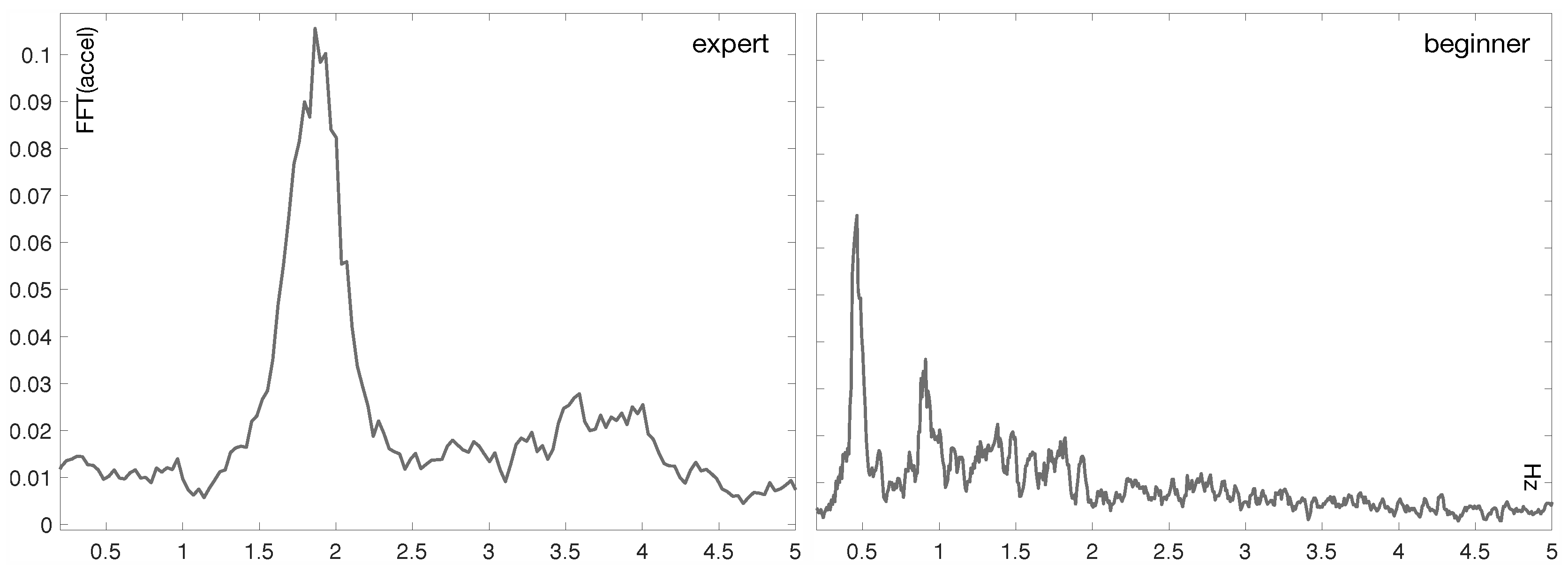
Figure 3 shows two plots of the FFT (Fast Fourier Transform) of the acceleration signal recorded with an iPhone 5 for two aikido practitioners (i.e., an expert and a novice one, respectively) performing the
shikko movement. The plot corresponding to the expert clearly reveals a central frequency around 2 Hz. On the contrary, the FFT signal related to the newcomer is more heterogeneous.
4.2. Scientific-Range Three-Axis Accelerometer Puck
In order to record and replay some specific martial arts-related motions, smaller and more precise sensing devices might be required. For instance, a tiny accelerometer apparatus (such as the AX3) could be mounted on the tip of a wooden sword or bokken in order to explain the concept of the linear (also called tangential) acceleration, among others.
The AX3 (Axivity, Ltd., Newcastle upon Tyne, UK) is a low cost CE approved logging three-axis accelerometer. The sensor uses a non-volatile flash memory chip and is accessible through a USB-enabled micro-controller. The device is suitable for use in a variety of environments (it is even water resistant up to 1.5 m). The accelerometer has a variable sensitivity to allow it to be used in many applications. The selectable ranges (to balance sensitivity against dynamic range) are: , , , and , where is the acceleration due to gravity. Accelerations outside the selected dynamic range result in saturation (clipping) of the recorded acceleration. The dynamic range of the accelerometer has no effect on the battery life or memory constraints. This last fact allows us to set the limit of this dynamic range at g, which is ideal for measuring the three components of the acceleration in fast swing movements.
The AX3 logs time series internally in a binary packed format. This format is named
continuous wave accelerometer format (CWA) and is very efficient for storing large amounts of data. Its specification is free and there exist implementations for many data processing frameworks, although the use of the default software, OmGui v43 (Axivity, Ltd., Newcastle upon Tyne, UK), is recommended. The AX3 also has a built-in, real-time clock and calendar, which provides the time base for the recorded acceleration data. However, in order to better align/sync the external video stream and the inertial data, we propose the methods described in
Section 5. Finally, the AX3 has been used and validated in many scientific studies such as [
23,
24].
Even though these types of discrete inertial sensors are, a priori, more accurate than the ones present in consumer-level smartphones, the use of these widespread devices is still totally adequate for the academic purposes described in this work.
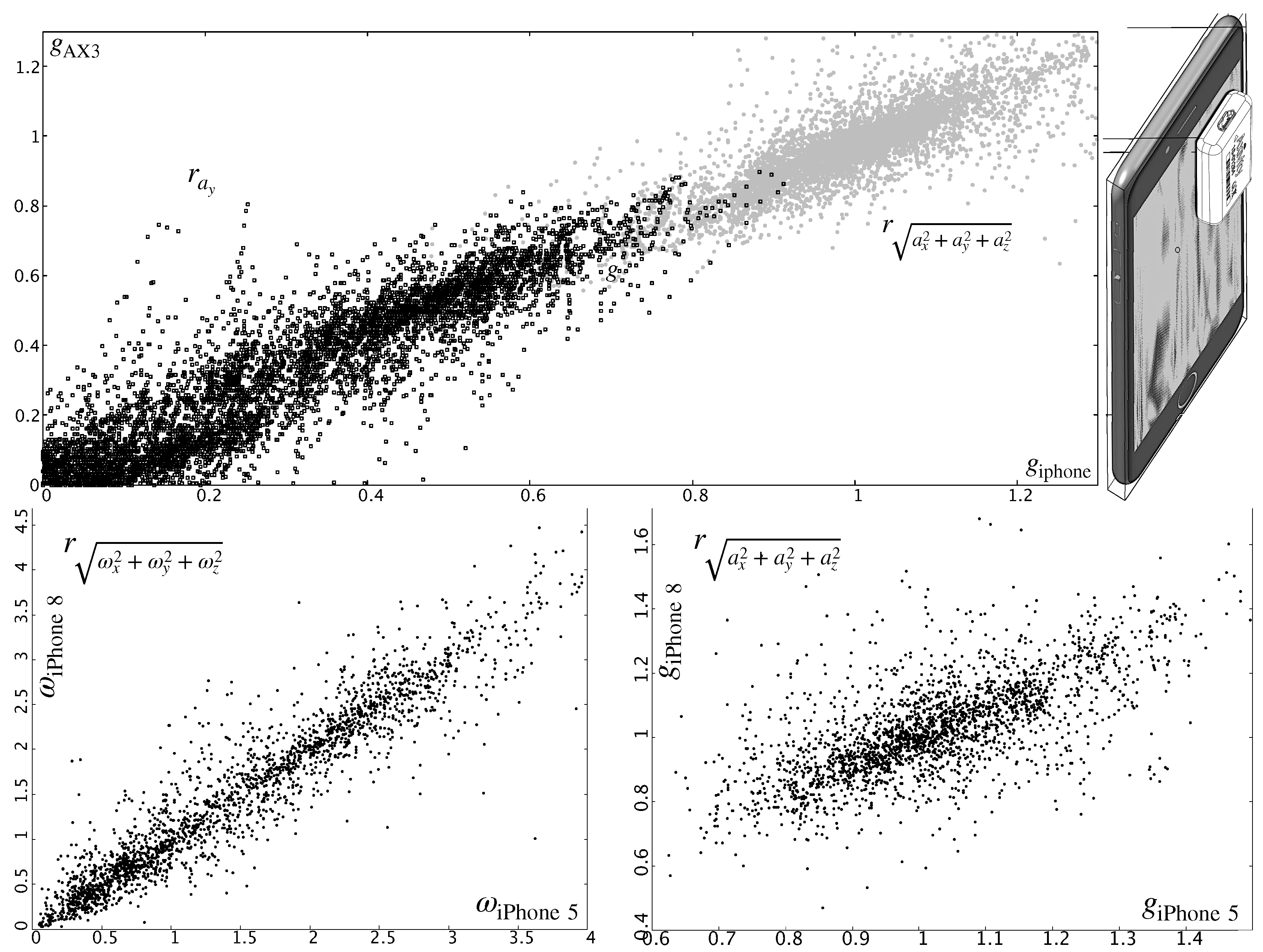
Figure 4—top shows the correlation in the acceleration measured by an AX3 device and the iPhone 5 smartphone described in
Section 4.1. In order to obtain this plot, the AX3 sensor was set aligned relative to the approximate location of the inertial unit. This location can be more or less known or it can be estimated through a (side) didactic experience [
25]. Besides, the quality of the signals among different smartphone models is quite similar, even if they are shipped 3 or 4 commercial seasons apart (as evinced in
Figure 4—bottom).
4.3. Stereoscopic Cameras
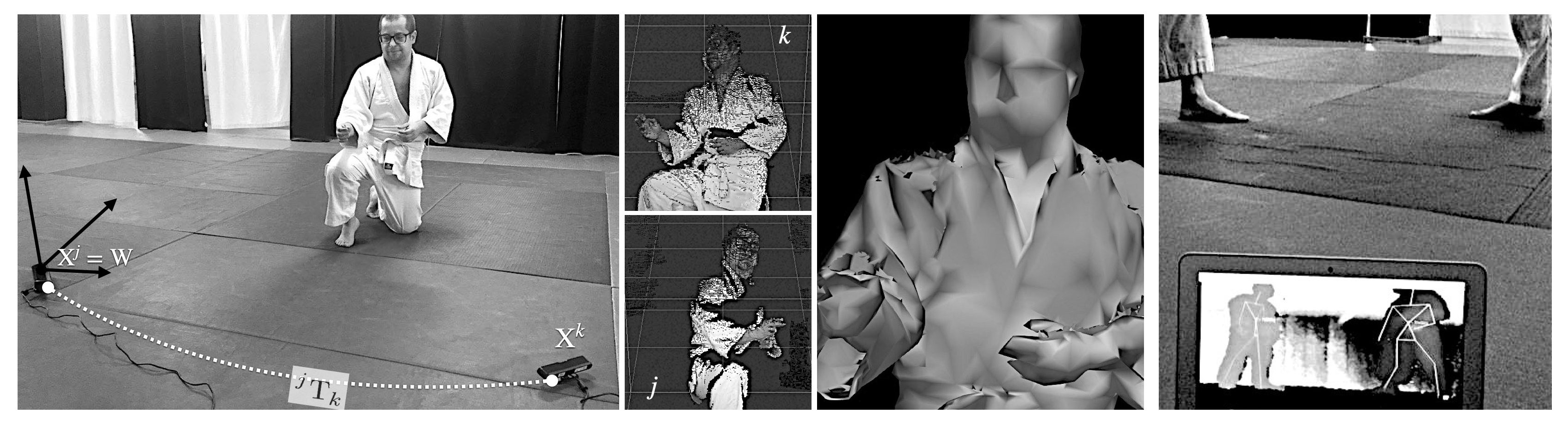
In order to collect motion data, it is also possible to use a pair of webcams in a stereoscopic configuration, as shown in
Figure 5—left. Each camera defines its own geometrical setting (
j,
k), and the coordinates of their focal point is labeled with
and
, respectively. This combined optical information can be used to three-dimensionally track, for instance, the face of the aikido practitioner (as seen from each video system), and, therefore, infer his/her location in the room. From this position (and in combination with time), it is also possible to extract other physical parameters, such as speed or acceleration. This step is also part of the intelligent registration system described in
Section 5.2.
Other means of optically tracking moving bodies, such as dedicated fiducial markers, can be used. However, we suggest the exploitation of the simplest and most direct fiducial marker possible: a person’s own face. A fiducial system also allows the derivation of the
pose of each camera (location and orientation relative to a fixed point in the scene). These types of fiducial systems are different from the ones tackled in
Section 5.1, whose goal there is to synchronize (in time) the video and the motion data acquired by other devices. Face-tracking algorithms are nowadays very easy to implement and can smoothly run even in web-based environments. Two good examples are [
26,
27]. An example of our efforts in this area is commented in
Section 6.4.
The stereoscopic camera system is directly wired to a simple integrated computer that accommodates the dual video data. In order to combine several images of the same practitioner at each geometrical setting, we need the associated camera projection matrices
,
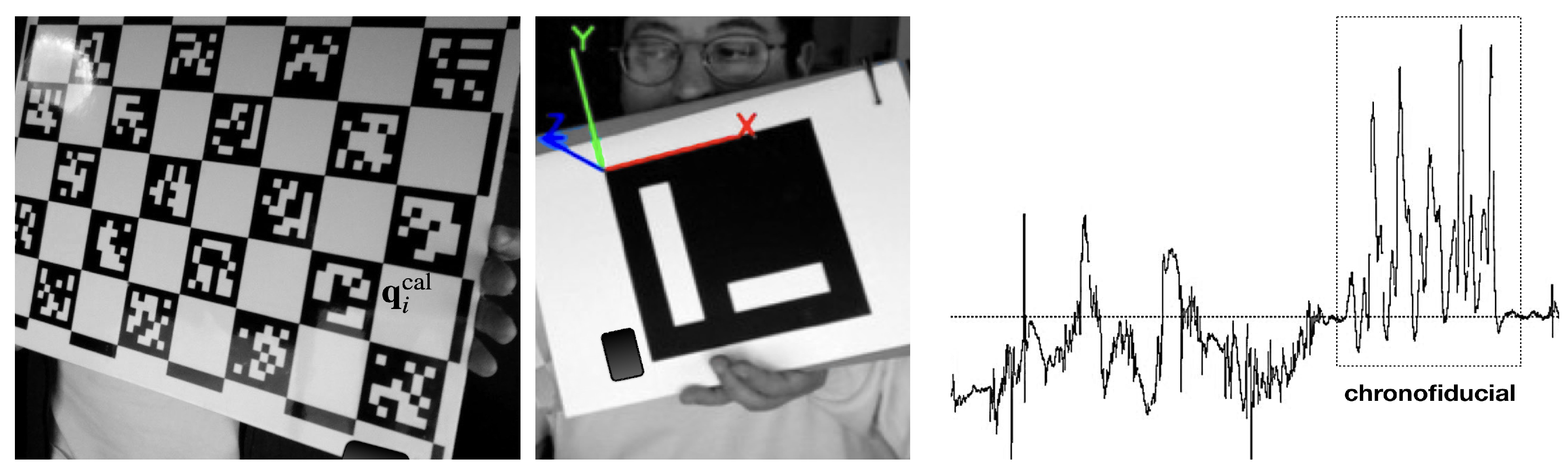
. These matrices are calculated in advance through a quick calibration phase with, for instance, a classical chessboard pattern [
28], as shown in
Figure 6—left. These calibration frames are also equipped with fiducials
that are then projected (when photographed) to
spots in the image. In the case of a chessboard panel,
,
, etc., are the intersections of the white and black squares (which can be automatically identified). Combinations of
,
pairs are then fed into the
direct linear transform or DLT [
29] and projection matrices can then be derived. With
and
, we can finally relate 3D points
(expressed in an external coordinate reference frame called
world or
), with their 2D
observed projections
,
on each image pair (
j and
k). For simplicity, we can define W to be coincident with
, that is:
, where
is the identity transformation matrix. Using projective geometry, we can write:
where
, and
,
are the homogeneous coordinates of
and
,
, respectively. With an RQ decomposition,
and
can be expressed as:
where
and
are two
upper triangular matrices that contain the intrinsic parameters of each camera system (for a given geometrical setting
j or
k) and
is a rigid transformation that translates 3D homogeneous points relative to W (coincident with
) to the coordinates of
. In other words,
geometrically connects the
focal point of both cameras. In addition, if both devices are from the same manufacturer (and same model), the intrinsic parameters in K are therefore the same and it is only necessary to calculate them once (i.e.,
). Sometimes, intrinsics can be easily derived from the camera specifications (e.g., sensor width and height and optical focal length).
The process of deriving 3D info from pairs of registered images is also known as
projection-to-volume reconstruction or
projective reconstruction and is described in Section 12.2 of [
30]. It enables the determination of the 3D location of an observed point
in two images (
j and
k). Given two projection matrices
and
and using Equation (
1), we can write:
where
and
represent the ground truth. Since we are working with homogeneous coordinates, the equivalence between two points has to be expressed using the cross product:
Each of these expressions determines two linearly independent equations that can be written in the form of a linear system. When solved through a single value decomposition method (SVD), we can derive the 3D location of a specific point
observed in the two images (
Figure 5—left/center). All these mathematical operations involve simple matrix operations that students at high-school levels can comfortably carry out (and/or the teacher can explain their calculation with open source tools [
31]).
4.4. Depth Cameras
Modern depth cameras rely on the acquisition of
point clouds. These data structures can be obtained with devices such as the reputed Microsoft Kinect™ or other OpenNI-compatible sensors [
32], like the ones shown in
Figure 5—right. A point cloud is an organized or unorganized set of points
in a 3D space whose coordinates are usually expressed relative to the W frame.
Modern consumer depth cameras use
structured light and machine learning. Inferring the position of a body entails: (1) computing a depth map (using structured light) and (2) inferring the position of the body by means of machine learning. The depth map is built by analyzing a speckle pattern of infrared laser light. This entails the projection of a known pattern onto the scene and the determination of its depth from the deformation of the aforementioned ornaments. There exist several machine learning implementations for skeleton tracking. One of the most widely used and deployed versions (and also embedded in the software inside many of the consumer sensors) is NiTE, succinctly described in [
33]. These kinds of sensors have also been used to monitor and infer movements from practitioners in other martial arts, such as Taekwondo [
34]. Kinect-like devices not only measure depth, but, as affirmed above, they can also report a body’s position and track movements with fair precision, even for specific body parts and quick movements. This feature is shown in
Figure 5—right to track the movement of two aikido practitioners when performing a movement called
shomen-uchi kotegaeshi.
If two depth cameras are registered (as explained in
Section 5.2), it might be possible to achieve a minimal stitching of both point clouds and derive the corresponding isosurface (
Figure 5—center). This meshed compound can be refined thanks to hole-filling and smoothing algorithms present in widely used free software packages, such as MeshLab, Blender or Paraview. The generation of this volume turns out to be very useful to estimate the moment of inertia, as discussed in
Section 6.1.
5. Generating Learning Material with Phy + Aik
We now describe how our approach Phy + Aik can generate synchronized multimedia educational material tagged with inertial data that can be useful in teaching some important physics concepts, such as the moment of inertia, its relationship with the angular velocity and the conservation of the angular momentum (which is especially relevant in the shikko movement). This is obtained with the generation of high-quality videos and visual compositions that simultaneously display aikido movements and the corresponding stream of inertial data. Through simple movement monitoring sensors and visual tracking devices (e.g., simple video cameras, depth recovering gadgets, etc.), it is possible to provide a creative way of teaching STEM concepts that can be truly understood by high-school engaged students.
One of the strengths of
Phy + Aik is grounded on the fact that the number and type of the interplayed sensors can grow at will while maintaining a gentle profile of affordability and ease of use. In fact,
Phy + Aik can start with a single smartphone (as mentioned in
Section 4.1), which is nowadays a ubiquitous low-price device. Nevertheless, as the amount and variety of sensors grows (such as those described in
Section 4), it becomes necessary the design of an
intelligent framework that alleviates and automates as much as possible the necessary registration/calibration phase. This step becomes even more critical when video data are added to the
information mix. However, before describing our full (and automatic) approach to this technical obstacle (
Section 5.2), we quickly review next a semi-automatic scenario. This setting may turn out to be more appropriate (and less complex) for the case of having just an inertial sensor and a video stream. In addition, in
Section 5.3, we comment on the possibility of carrying out live demonstrations to present visual educational materials to the students.
5.1. Manual Video and Time Series Data Alignment
Data alignment can be achieved with, for instance, ELAN (EUDICO Linguistic Annotator). ELAN is a tool that allows the creation, edition, visualization and search of annotations within video and audio data. It was also originally developed with the aim to provide a technological basis for the annotation and exploitation of multi-media recordings. Certainly, it is specifically designed for the analysis of language and gestures, but it can be used for other purposes. For instance, thanks to its annotating capabilities, it is possible to sync (i.e., align in time) video and streams of inertial data. In fact, a key aspect when capturing experimental data is to spatially (and chronologically) register several streams of data and ELAN excels at this feature. Even though these streams are sometimes time-tagged in advance, they may have insufficient resolution or be out of phase with one another. For this reason, in order to achieve such registration, it is necessary to place visual markers in all of the involved streams. Such markers can retrospectively be used to identify certain event starts and stops.
A good time marker or chronofiducial should have the following characteristics: be tolerant to the orientation of the devices, be easily identifiable in the data set, occur over a short period of time, and be repeatable. With this approach, video and time series alignment is carried out manually. In the next section, we propose an automatic/intelligent framework that not only simplifies this positioning operation, but also ensures that all video/depth capturing devices and inertial sensors are registered both in a space and time coordinate frame.
5.2. Intelligent Framework for Multi-Sensor and Video Registration
In this section, we propose an intelligent framework for multi-sensor and video registration. The goal of an automatic registration (or calibration) phase is to unattendedly locate a set of spatial and chronofiducials (introduced respectively in
Section 4.3 and
Section 5.1) in the streams provided by different sensors. The registration step may also deliver the intrinsic parameters of the available cameras (RGB, depth, etc.) and its geometrical relation with other contour recognition equipment. These transformations remain invariant during the execution of the aikido practice (such as the
shikko movement) and/or as long as the multi-imaging system moves rigidly.
A simple chessboard-like registration frame (shown in
Figure 6—left) was designed to help during this phase. To be more specific, the chessboard pattern is not the classical one based on equally spaced black and white squares, but on the system devised by [
35]. The advantage of this fiducial set (and the associated algorithm and C++ implementation) is that it is very robust and fast, even under occlusion events. The board also contains a rigidly attached inertial sensor. This sensor can be a smartphone or even a discrete sensor (such as the one mentioned in
Section 4.2) and can be placed on the front face of the registration board or on its back. With this marker set, we can derive the camera equations and the geometrical relation between the conventional cameras and other present contour sensors. In the case of OpenNI-based depth cameras, integrated video and depth streams are usually pre-registered as a factory default setting, which turns out very helpful in the registration phase: the reported 3D data are already expressed (
pre-transformed) relative to the RGB optical center. The registration process proposed, which is very similar to the one described in [
36,
37], can be summarized as follows:
The registration frame is introduced in the scene and placed as still as possible (this is the only manual step). Video (and depth, if applicable) streams are continuously recorded. It is assumed that each system manages its own real-time clock and that those streams are a priori out-of-sync. Modern video and multimedia containers (Quicktime, Matroska, etc.) usually have encoded a
creation_date metadata item that accounts for the date and time in which the recording started [
38], according to the computer managing the video capture. The teacher just has to make sure that the pattern in the registration frame is correctly visible by every camera (and/or the video counterpart of all the present depth cameras) without interruption.
Using the
direct linear transform (DLT) algorithm [
30], the 3D location
of each marker in the board (corners) and the coordinates of the corresponding 2D projections
in the images, we obtain the registration matrix for each device. It is assumed that optical distortions and intrinsic parameters have been previously derived or are known (device manufacturer specifications). This process is automatic and can run in real time in modern (but still modest/low price) hardware. Preliminary results can even be shown as graphical overlays.
Using the video streams of the registration frame (and its detected visual markers thanks to the OpenCV-based algorithm presented in [
35]), it is possible to obtain the rigid transformations that link the reference frames of all devices. In this way, all cameras can now be virtually positioned relative to a common (spatial) coordinate system.
The board is then shaken
N times. During this phase, the board appears
blurry from the point of view of all video/depth devices and fiducials are no longer detected (corners also appear fuzzy). However, the attached inertial sensor does effectively
sense and measure this (also
timestamped) wavy time series pattern. In this context, the rules regarding the generation of chronofiducials (listed at the end of
Section 5.1) are fully respected.
An intelligent peak detection process is executed following the algorithm described in [
39] in order to find the series of
N-spikes in the acceleration stream of a chosen Cartesian axis (depending on the position/orientation of the inertial sensor in the registration board and the specific selected direction of agitation). The chronofiducial (needed for the time alignment) is established as the moment in which the first agitation/peak in the signal took place.
The initial
pose (relative orientation) and location of all inertial sensors (if there are more present than the one stuck to the registration board) is determined by attaching a corresponding coplanar visible fiducial, as in the example shown in
Figure 6—center.
Likewise, these sets of sensors and visible markers are shaken the same number of N occasions. The intelligent peak detection commented in step 5 is also run for those inertial series.
All time series/stamps are finally aligned (in time) and, as stated in step 3, the geometrical transformations of all sensors are derived relative to the W frame (i.e., one of the video cameras).
With this approach, even with humble hardware and modest computing setups, it is possible to achieve an unnoticeable time lag in the registration of all video/inertial signals. It is also feasible to achieve a spatial resolution of 1 cm. All in all, the resolutions/precisions delivered by this automatic intelligent framework are adequate for the academic purposes described in the scope of Phy + Aik.
It is very important from a pedagogical, psychological and perceptual point of view to have the correct synchronization of all data streams. To our knowledge, this approach has not been proposed previously. The inertial data can be stored for later production of high-quality videos or real-time streamed to projectors or big screens in auditorium rooms. This comes very much handy when using Phy + Aik approach during presentations (and also during live exhibitions), as discussed next.
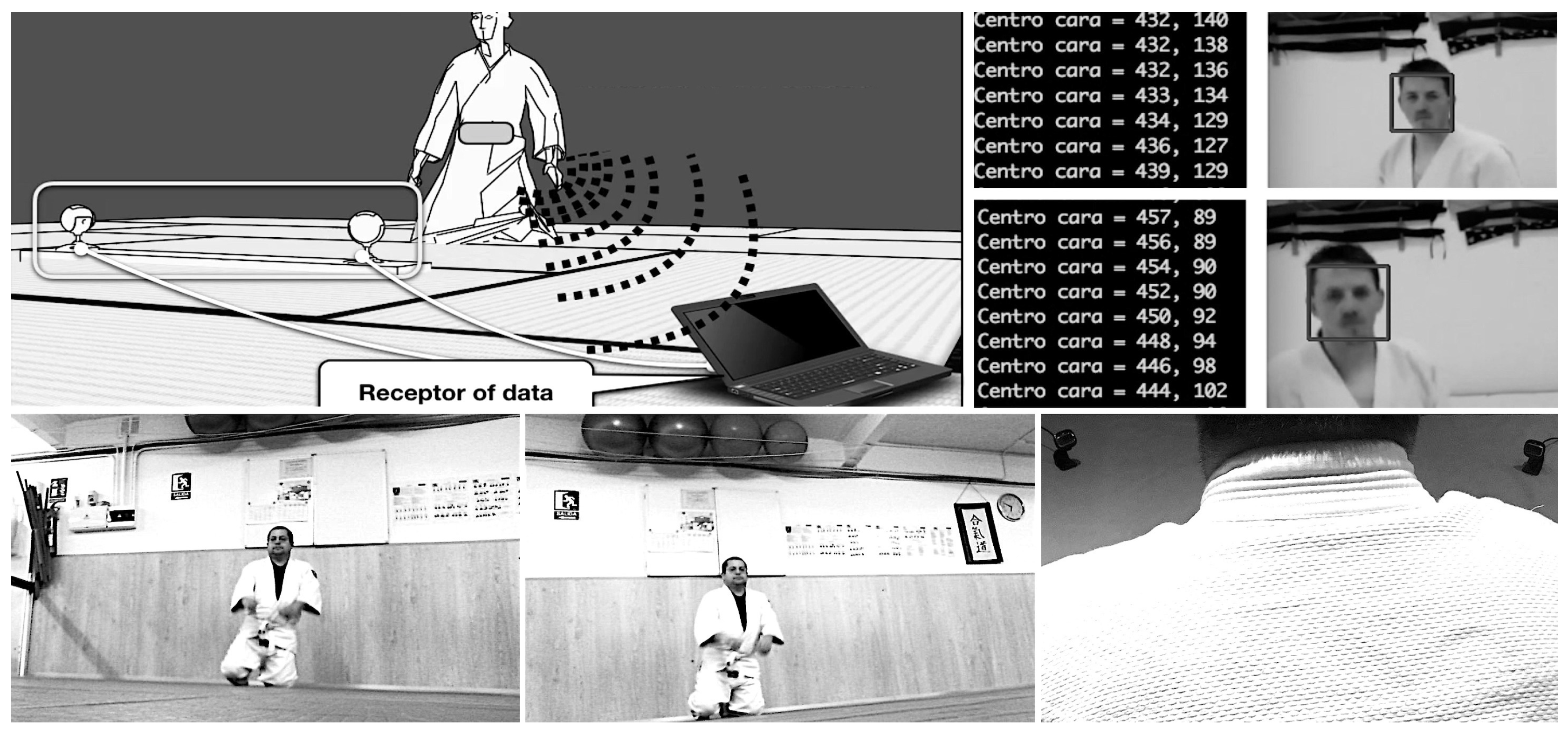
5.3. Real-Time Stream of Data
Live demonstrations are also a key component in education even if that implies that the student apparently remains as a passive viewer of a screen with data. This concept has been coined as
interactive screen experiment [
40]. In
Phy + Aik, we have also had into account these scenarios in which aikido techniques take place live and direct in front of an audience of motivated learners. In these environments, students can witness (or even perform by themselves in a tutored way) the execution of these aikido movements while they can simultaneously read the inertial signals (captured by the worn sensors) in big monitors and external screens. In this context, the broadcasting and live data plot can be achieved mainly by combining UDP-stream of inertial data and screen sharing. Both approaches were tested also during the 2019 Education Week, but in another event called AULA 2019, in the context of the activity
Aikido and Artificial Intelligence organized on March 29th (between 15:00 and 17:00 h) in the UNED stand, and also with the participation of black-belts of the
Aikime dojo. During the live demonstration at AULA 2019 the aikido practitioners wore a smartphone attached to their waists on the
hara point and performed several techniques in front of the audience, including the
shikko movement as shown in
Figure 1—center, to show in real-time and on a big screen the change of the inertial signals in relation to the movements being performed.
7. Conclusions and Future Work
In this paper, we have presented Phy + Aik, a STEAM-based approach whose goal is to introduce a range of physics-related ideas to high-school students through curated educational materials that combine aikido techniques with the data gathered by a variety of inertial and optical sensors. To test our approach, we carried out a field study with high-school students that confirmed that the concept of moment of inertia is better understood by watching live demonstrations of aikido techniques. Phy + Aik interplays the inertial information gathered by motion sensors and the input of video/depth recording devices into a registered common space-time reference frame. These data aggregation and stream registration can take place in a semi-manual manner or in an almost automated way thanks to the intelligent registering framework also described in the text. In this context, inertial sensors, cameras and depth sensors are arranged into an organized four-dimensional space coordinate system through the use of markers (both in the space and time dimensions). These fiducials are, in turn, automatically detected. With Phy + Aik, educators can either produce innovative visual educational lectures consisting of high-quality videos (synchronously tagged with the inertial data collected by motion sensors), or organize live demonstrations in collaboration with aikido practitioners/masters.
Our future research is framed in the INT
2AFF project (
INTelligent INTra-subject development approach to improve actions in AFFect-aware adaptive educational systems), where we plan to explore the affective life cycle when learning STEM concepts with the support of martial arts. In any case,
Phy + Aik is a first step toward the design of intelligent psychomotor tutoring systems, where students’ movements are used as input data in the tutoring system so that personalized STEM contents based on students’ motion information can be recommended, as discussed elsewhere [
7]. For this, motion information obtained with inertial sensors can be modeled with artificial intelligence techniques [
48].


