Abstract
Cloud radio access network (C-RAN) is a promising technology for the Internet of Things (IoT). In C-RAN, the remote radio head (RRH) and baseband unit (BBU) in the conventional base station are separated, and each BBU is backward centralized into a virtual BBU pool. In this paper, we consider the uplink transmission for the two-user C-RAN with two RRHs under a block fading channel. A novel rateless coded transmission scheme is designed. During each transmission round, each user keeps transmitting to the RRHs using Raptor code until the BBU pool feeds back an acknowledgement (ACK). With the proposed scheme, each user does not require the instant channel state information, which greatly reduces the system overhead. We also design the quantizer at the RRHs and the iterative multi-user detector and decoder at the BBU pool, based on the belief propagation (BP) algorithm. For the Raptor code applied at each user, we optimize the corresponding output node degree profile, based on extrinsic information transfer (EXIT) analysis for the decoding process at the BBU pool. The resulted degree profiles are optimal in an average sense under all possible channel states. The simulation results show that the rateless coded transmission scheme with the optimized degree profiles outperforms the benchmark degree profile in both bit error rate and average system throughput. Moreover, the achieved performance is close to the theoretical limit.
1. Introduction
The Internet of Things (IoT) is the trend of the next generation of communication networks. To achieve the IoT, information collection needs to be completed by massive sensors [1]. The International Data Corporation predicts that by 2020, the number of internet-connected devices in the IoT will grow to 50 billion [2]. The large amount of data generated by sensors and devices will create huge network traffic, which brings great challenges to the traditional wireless access networks. On the other hand, it has been noted in [3,4,5,6] that cloud radio access network (C-RAN) is a promising wireless network architecture which can adapt to the rapidly growing IoT traffic and improve the Quality of Service (QoS).
C-RAN is characterized by the separation of the remote radio head (RRH) and the baseband unit (BBU) of each access point in the network. In C-RAN, each RRH is located closer to the user, while each BBU is backward centralized into a virtual BBU pool. The BBU pool and RRHs are connected by high-speed fronthaul links. Since joint signal processing for multiple RRHs can be realized at the BBU pool, C-RAN can achieve a considerably higher spectrum efficiency compared with the traditional cellular networks, and C-RAN can also improve network resource utilization, reduce interference, and reduce energy consumption and overall hardware costs [7,8].
1.1. Motivation and Related Works
There exist several issues for the implementation of C-RAN. Firstly, the limited fronthaul link capacity imposes restriction on the data rate between RRHs and the BBU pool. Therefore, signal compressors are necessary at both sides [9,10,11,12]. Secondly, the additional latency introduced by fronthaul will cause stricter restriction on the decoding time at the BBU pool under the conventional hybrid automatic repeat-request (HARQ) framework [13]. Thirdly, for joint signal processing at the BBU pool, global information about the network states and channel states is needed. In consideration of the system overhead, it is nearly infeasible for the transmitter to obtain instantaneous global channel state information. This poses challenges for the application of traditional HARQ-based fixed-rate channel coding (such as low density parity check (LDPC) code and Turbo code) in C-RAN, with which the coding rate of the transmitter is chosen based on the current channel state feedback by the receiver, and the decoding time at the receiver is restricted in order to support HARQ [13]. On the other hand, rateless code (such as Luby transform (LT) code and Raptor code [14]) can encode the information into a codeword of infinite length. With rateless code, the transmitter continuously sends the codeword to the receiver until the latter feeds back an ACK. The performance of rateless code depends on the so-called output node degree profile [14]. The optimized rateless code can perform close to the channel capacity even without instant channel state information [15]. The above properties make rateless code a promising channel coding candidate for C-RAN.
C-RAN has been widely investigated, and there has been a plenary of work on various aspects of C-RAN, e.g., [16,17,18,19,20,21,22,23,24,25,26,27,28,29,30,31]. The network structure and the function split between RRHs and the BBU pool in C-RAN were discussed in [16,17,18]. Literature works [10,20] investigated resource allocation and management in C-RAN. Non-orthogonal multiple access (NOMA) was considered in C-RAN [21,22], where energy efficiency was analyzed and optimized. As for the physical layer, existing work mainly focused on the compressor and pre-coder design at the RRHs, wherein the signal dependence at the RRHs can be utilized to increase the compression rate [23,24,25], and the compressor and pre-coder can be jointly optimized for a higher system achievable rate [26,27,28]. Considering the channel coding in C-RAN, authors in [29,30,31] made efforts on the design and implementation of fixed-rate code, i.e., Turbo code and LDPC code, and the performances of decoding algorithms were evaluated on cloud computing platforms. On the other hand, rateless code, such as LT code and Raptor code, has been studied in various communications systems, including wireless broadcast systems [32], distributed antenna systems [33,34] and relay systems [35,36], but these cannot be directly applied to C-RAN. The application of rateless code as channel code in C-RAN has not been discussed until recently [37,38,39]. In [37], we considered Raptor code for the multi-user downlink of C-RAN, where both the precoder and the degree profile of Raptor code at the BBU pool are jointly optimized under an additive white Gaussian noise (AWGN) channel. In [38,39], a rateless coded transmission scheme was designed for single-user uplink C-RAN, and the degree profile of the user was optimized under both AWGN and a block fading channel.
1.2. Contributions
In this paper, we consider the design of a rateless coded transmission scheme for two-user uplink in C-RAN under a block fading channel. It should be noted that in the proposed scheme, instant channel state information (CSI) for each user is not required. For each transmission round, each user encodes its own message using Raptor code with a pre-optimized degree profile which is fixed over all transmission rounds, and simultaneously transmits to the RRHs. Each RRH compresses its received signals and uploads to the BBU pool for joint signal processing. Upon the BBU pool recovering the messages of both users and feeding back an ACK, the current transmission round ends. We summarize the main contributions of this paper as follows:
- (1)
- We propose a rateless coded uplink transmission scheme for two-user C-RAN with two RRHs, including the quantizer at each RRH and the iterative multi-user detector and decoder based on the belief propagation (BP) algorithm at the BBU pool.
- (2)
- We resort to extrinsic information transfer (EXIT) to analyze the iterative detecting and decoding process at the BBU pool. Based on this, the condition for successfully decoding is derived.
- (3)
- Based on the EXIT analysis, we optimize the degree profiles of the Raptor code for each user. Explicitly, we search the optimal degree profiles to minimize the threshold signal-to-noise ratio (SNR) under a fixed average Raptor code length and the condition of successfully decoding over all possible channel states. Therefore, the resulted degree profiles are optimal in an average sense over all possible channel states.
Note that compared with the single-user case in [38,39], rateless coded transmission design for multi-user C-RAN uplink is more challenging. Firstly, the receiver structure for a multi-user case is more complicated than for a single-user case, wherein joint de-quantization, multi-user detection and channel decoding should be performed at the BBU pool. Secondly, the rateless code profile optimization scheme for the single-user case cannot be directly adopted here, due to the fact that the EXIT of the decoding process is totally different from the single-user case.
Organization: This paper is organized as follows. In Section 2, we introduce the system model. The rateless coded uplink transmission scheme is presented in Section 3. In Section 4, EXIT analysis and degree profile optimization are discussed. Simulation results are shown in Section 5, and Section 6 concludes the paper.
2. System Model
The considered uplink C-RAN system is depicted in Figure 1, which consists of two users, two RRHs, and the BBU pool. Both users and both RRHs are equipped with a single antenna. For the wireless link from user , to RRH , the channel gain is denoted as .
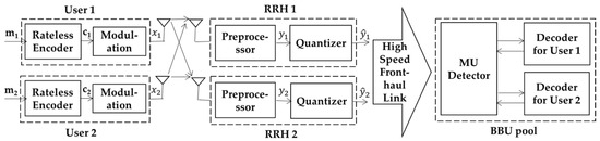
Figure 1.
Rateless coded transmission for two-user uplink in cloud radio access network (C-RAN) with two remote radio heads (RRHs).
We assume that the wireless links experience block fading. The channel gain of each link remains constant during one round of transmission, but independently and randomly changes round by round, satisfying some probability distribution (e.g., Rayleigh distribution). As for the receiver side, the BBU pool has the knowledge of the instant channel gain between each user and RRH. On the other hand, the user is not required to be aware of the instant channel information. During each transmission round, the two users continuously transmit to the BBU pool until the latter recovers the messages and feeds back an ACK. The detailed procedure of each transmission round is as follows.
Firstly, user , encodes its message of length using Raptor code to obtain the coded bits and then modulates the bits into symbols , which are sent to the RRHs. Note that the degree profiles used for Raptor encoding are fixed over all transmission rounds. At each RRH, the received signals are preprocessed into the baseband signals, which can be expressed as
where , , , is the base band signal at RRH j, is the transmission power of each user, is the independent additive white Gaussian noise at RRH j with a mean of zero and variance of .
Then, RRH j quantizes the baseband signals to meet the fronthaul link capacity restriction. The quantized signals are uploaded to the BBU pool through the fronthaul link. At the BBU pool, an iterative receiver structure with a multi-user detector (MU detector) and a channel decoder based on the belief propagation (BP) algorithm is applied. When the messages from both users are successfully recovered, the BBU pool feeds back the ACK via RRHs to inform the users to stop transmitting.
3. Rateless Coded Uplink Transmission Scheme
In this section, we present the detailed uplink transmission scheme based on rateless code. Firstly, we show the encoding process at the users. Then, the quantization scheme at the RRHs is given. Finally, we propose the iterative detecting and decoding algorithm at the BBU pool.
3.1. Rateless Encoder at the User
Each user applies Raptor code to encode its intended messages. Explicitly, to generate the coded bits at each user i, the message is firstly encoded by LDPC code with rate , and then by LT code with an output node degree profile:
where is the maximum output node degree and is the probability that a coded bit (also named ‘output bit’ in the following) is with degree .
Each output bit is generated as follows. The degree of each output bit is randomly chosen according to the degree profile (2). For an output bit with degree , bits are randomly picked from the LDPC coded message (also named ‘input bits’ in the following). These bits are XORed and the result is the value of this output bit. Through the above encoding process, the output bits can be generated infinitely. As for the modulation, for simplicity, we apply binary modulation, i.e., bits 0 and 1 are mapped to 1 and −1, respectively. The users continuously send the modulated signals until an ACK is received.
3.2. Scalar Quantizer at the RRH
In order to meet the limited fronthaul capacity, the baseband signal should be compressed at the RRH before being uploaded to the BBU pool. Here, we use a scalar quantizer with uniform quantization intervals. The number of quantization bits is determined by the fronthaul capacity limitation. Due to the concern of practicality, the quantization thresholds only depend on the number of quantization bits and the statistics of the channel gain.
According to (1), the base band signal at RRH j is
whose variance is calculated by:
where is the variance of the channel gain from user i to RRH j.
According to [40], it can be regarded that the value of is almost distributed in the range of . Let the number of quantization bits be and . Then, the signal at RRH j is quantized into according to the following rule:
where is the quantization interval and , for the quantizer at RRH j.
3.3. Iterative Detecting and Decoding at the BBU Pool
Figure 2 shows the decoding graph corresponding to the iterative detector and decoder at the BBU pool. Square nodes represent check nodes, and circular nodes represent variable nodes which are also named as input nodes or output nodes, as shown in the figure. The left and right subgraphs in the upper part of the figure represent the Raptor decoding graph for the messages from user 1 and user 2, respectively. The input nodes and output nodes in the Raptor decoding graph represent the corresponding input bits (LDPC coded bits) and output bits (Raptor coded bits), respectively. For simplicity, each output node and the associated LT check node are regarded as a whole and referred to as “output node” in the following. The lower part of the figure is the multi-user detector. and denote the log-likelihood-ratio (LLR) of the output bits of user i exchanged between the MU detector and decoders.
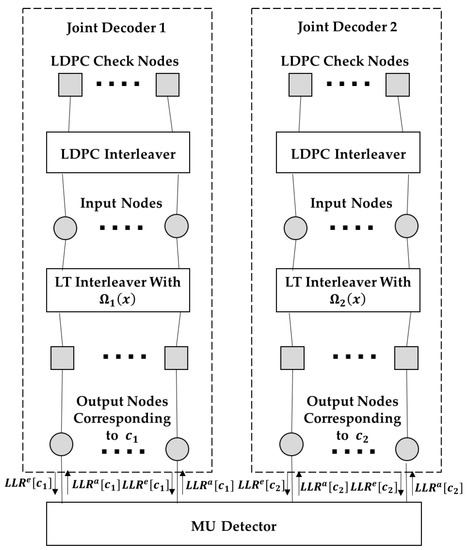
Figure 2.
Decoding graph at the baseband unit (BBU) pool.
The MU detector calculates the LLRs of the output bits of user i, i = 1, 2, according to the quantized signals and from both RRHs and the soft outputs from the decoders. The LLR of each output bit for user i is calculated by:
where equals 1, and the value of is 1 at the beginning of decoding and equals during the decoding iteration, in which is the soft output from the Raptor decoder for the other user i’ in the previous decoding iteration. Taking the case of as an example, the conditional probability in (6) is calculated as follows. Note that when fixing , the received signals and at the RRHs are Gaussian distributed. According to (5), we can derive:
where the integral range [] and [] denote the quantization intervals that and represent according to (5), respectively. As an example, if , the range for the first integral is . The other three conditional probability terms can be calculated similarly.
The iterative detecting and decoding is based on the BP algorithm [41], where ‘messages’ are interchanged along the edges between variable nodes and check nodes. Each ‘message’ along the edge is the LLR of the corresponding variable node (representing either the input bits or the output bits), which is connected by this edge. The whole decoding process can be divided into two stages. In the first stage, the decoding iteration is performed on the entire decoding graph (including the MU detector), until the mean LLR of the input nodes of both users exceed a predetermined threshold , which is the minimum requirement for successfully decoding the rate LDPC precoder and can be derived using the method in [31]. In the second stage, decoding iteration is performed individually on the LDPC decoding graph of each user to remove the residual errors. The detailed procedure of the first decoding stage is given in the following.
For the iteration , firstly, message passing is performed on the Raptor decoding graph of user 1, which is shown in step 1 to step 6.
Step 1: The message transferred from an input node i to an LDPC check node c is given by:
where is the message from the LT output node of user 1 to the input node in the previous round .
Step 2: The message from an LDPC check node c to an input node i is given by:
where is the message from the input nodes which are connected to the LDPC check node c (except the input node itself).
Step 3: The message from an input node i to an LT output node o is:
where the first summation is over all LT output nodes adjacent to other than itself, and the second summation is over all LDPC check nodes connected to i.
Step 4: The message from an LT output node o to an input node i is given by:
where is the message from the MU detector and is calculated by (6), and the product is over all input symbols adjacent to other than itself.
Step 5: transferred to the MU detector is given by:
Step 6: Update the message at the input code:
Then, a similar decoding procedure is performed on the Raptor decoding graph of user 2, and after that, one decoder iteration is completed.
When the mean LLR of the input nodes of both users (as given in (13)) exceeds , the second stage starts and message exchange will be individually performed on the LDPC decoding graph of each user. The specific process of this stage is similar to Step 1 to Step 2, and is omitted here. Figure 3 is the flow chart of the decoding procedure.
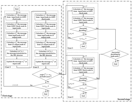
Figure 3.
Flow chart of the decoding procedure.
4. Decoding Performance Analysis and Degree Profile Design
In this section, we optimize the output degree profile of the Raptor code used by each user to further improve the achieved sum throughput of the system. Note that we assume that each user is not aware of the instantaneous CSI. Hence, it can only be assigned one optimized output degree profile, which is used to generate Raptor code during all rounds of transmission. Therefore, the objective is to find a universally good output degree profile in an average sense for each user under all possible channel states, with the knowledge of CSI statistics, i.e., the probability distribution of the channel state for each link.
4.1. EXIT Analysis of the Decoding Process
Before the degree profile optimization, we first analyze the decoding process at the BBU pool to derive the successful decoding condition. The analysis is based on EXIT [42]. Explicitly, we trace the update of the extrinsic information (EI) transferred between output nodes and input nodes in the decoding graph during the decoding iterations.
EI is defined as the mutual information between the LLR messages and the corresponding bits (i.e., input bits and output bits in this paper). It can be assumed that the LLR messages interchanged between the variable nodes and check nodes are symmetrically Gaussian distributed [42]. EI carried by LLR messages with a mean of and a variance of is given by [42]:
Before the EXIT analysis, some definitions are given first. Recall the decoding graph in Figure 2. The LDPC variable node degree distribution is defined as , where is the probability of an LDPC variable node with degree , and is the maximum degree of the variable nodes. (Note that both users employ the same LDPC code). The edge distribution of the LDPC check nodes can be defined as , where is the probability of a randomly chosen edge being connected to a check node with degree , and is the maximum degree of the check nodes. The distribution of the input node degree of user , is defined as is the probability of the input nodes of user with degree , and represents the maximum degree of the input nodes. The edge distribution of the input nodes of the user i is defined as , where is the probability of an edge connected to an input node with degree d. Both and can be approximated by the Poisson distribution with an average of [43]. The output node edge distribution of user i is defined as where represents the probability of an edge connected to the output node with degree . The relationship between and the output node degree distribution given in (2) is given below:
For ease of reading, we summarize the aforementioned definitions in Table 1, wherein .

Table 1.
Annotations to symbols.
As shown in Figure 4, we redraw the decoding graph of Figure 2 for a clearer illustration of the EI update procedure between each node during the decoding process. The EI update during the decoding iteration is given in the following, which corresponds to the decoding process given in Section 3.3.
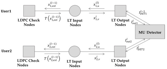
Figure 4.
Extrinsic information (EI) transfer on the decoding graph during the decoding iteration.
For the lth iteration of the first stage decoding, firstly EI is exchanged on the Raptor decoding graph of user 1, i.e., on the upper part of Figure 3:
Step 1: The LLR messages are transferred from user s input nodes to the LDPC check nodes. The EI of the messages is:
where is the EI of the messages from the output nodes to the input nodes in the )th iteration.
Step 2: EI from the LDPC check nodes to the input nodes of user 1 is:
Step 3: EI from user 1’s input nodes to the output nodes is:
Step 4: EI from the output nodes of user 1 to the input nodes:
where is the EI of the messages from the MU detector. Its value is determined by the channel matrix and the EI corresponding to the messages from the output nodes of user 2 in the th iteration. The derivation of will be discussed later.
Step 5: EI from LT output nodes of user 1 to the MU detector:
The EI update on the Raptor decoding graph of user 2 is similar, which is omitted here.
In step 4, is the output EI from the detector. The input EI is , which is the EI from the LT output node of user 2 to the detector. This function can be numerically derived by Monte Carlo simulations [44]. In detail, transmitted symbols and of user and user 2 are generated, respectively. For user 1, the symbol value is fixed to be 1, while for user 2, the symbol value is randomly 1 or −1. With randomly generated Gaussian noise samples, samples of quantized signals from each RRH can be generated. For each fixed , we generate samples of from the symmetric Gaussian distribution with mean and , depending on the corresponding being either +1 or −1, respectively, where is calculated from (14). Then, samples of can be generated. is evaluated using the histogram for the probability distribution of . According to the results of Monte Carlo simulations, we find that under fixed , can be well approximated by a linear function:
where and are coefficients which can be determined by two end points of the line, i.e., and . Figure 4 shows an example where = −2dB, the number of quantization bits at the RRH is eight, three channel matrices H are considered: case 1 is , case 2 is , and case 3 is . From Figure 5, one can find that the linear lines (called LA in the figure) well approximated the Monte Carlo simulations (called MC in the figure).
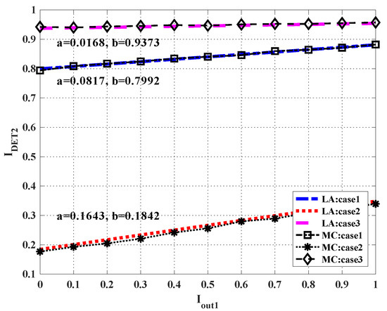
Figure 5.
Extrinsic information transfer (EXIT) chart for the multi-user (MU) detector.
With step 1 to step 5 shown in the above, we can trace the update of in each decoding iteration (recalling that is the EI from the output nodes to the input nodes of user i). To guarantee the successful decoding at the second decoding stage which is individually performed on the LDPC subgraph, should exceed a certain threshold before the maximal decoding iteration times. Therefore, we derive the successful decoding condition: , where is the maximal decoding iteration times. Here, the threshold EI can be calculated from the following equation (recalling that is the minimal LLR required for LDPC successful decoding):
4.2. Degree Profile Optimization
With the above EXIT analysis, we optimize the degree profile of the Raptor code adopted at each user. The task is to find a uniformly good output degree profile for each user under all possible channel states, with the knowledge of the probability distribution of each channel state.
Recall that the channel matrix remains invariant within each round of transmission and varies independently round by round. For each round, both users continuously transmit the Raptor codeword until the BBU pool decodes both messages successfully. Hence, the length of the Raptor codeword for each user is related to the channel matrix in each round, which can be expressed as:
where is the average degree of the LT input nodes for user i under channel matrix . Note that during each round of transmission, the two users start and stop transmitting simultaneously, therefore we have .
In general, the channel matrix space is continuous. In practice, we discretize the space into states: . The probability of each state is denoted as . The average Raptor code length over all channel states can be expressed as:
Apparently, .We can approximate as [45], where is a constant and is independent of the channel matrix. is the theoretically maximal achievable rate of user i with transmit power under channel matrix . can be calculated as follows.
According to (1), the two-user C-RAN can be regarded as a two-user multiple-input-multiple output (MIMO) system with two antennas at the receiver. Note that to be precise, the latter is the ideal case of the former wherein the quantization error at RRHs is ignored. The capacity region of the two-user MIMO system is depicted in Figure 6, and can be expressed as:
where and denote the achievable rates of user 1 and user 2, respectively. The derivation of each entropy term is not difficult, thus it is omitted here. Note that in our setting, both users have the same message length and transmit simultaneously (i.e., the times of channel usage for both users are the same). Therefore, the achievable rates of the two users are always the same. The maximal achievable rate for both users should be the intersection point of the line and the capacity region boundary, which is given by
where , and are the right-hand sides of (25), (26) and (27), respectively.
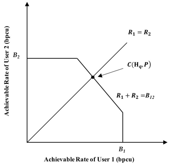
Figure 6.
Capacity region of the two-user MIMO system.
Note that the average network throughput can be expressed as . Thus, it is inverse to the average Raptor code length of each user. Our optimization object is to find the optimal degree profile that minimizes the average code length while guaranteeing successful decoding at the BBU pool under all possible channel states. However, this problem is difficult to solve and the linear programming method in [39] cannot be applied here. We transform the original optimization problem. Instead, we minimize the required SNR for successfully decoding with a fixed average code length. Note that a similar technique has been used in the AWGN case for a multiple access relay channel [44]. In our problem, the fixed average code length is derived as a lower bound of the code length for each user to successfully deliver a message of length , as given below:
The optimization problem is given as follows:
In the above problem, is the starting condition for BP decoding, where is a small number. guarantees successful decoding with the average input node degree and degree profiles under all channel states, where l’ is the maximal decoding iteration times. is from (24) and (29), i.e., the average code length is fixed to L. We solve the above optimization using the differential evolution (DE) method [46]. The common DE includes mutation, crossover and selection operations. The procedure is as follows:
- (1)
- Initialization: We first initialize the vector population as the 0th generation, where each vector individual represents one degree profile, and NP is the number of individuals. represents the coefficient for degree b in the profile, and dc is the maximal degree. should satisfy the conditions of and in the problem (30).
- (2)
- Mutation: For the th generation, the mutation vector of the next generation can be generated bywhere is a scaling factor (we choose in this paper), and , and are random integers between 1 and NP.
- (3)
- Crossover: Cross and to get (where , ):where is the crossing probability (we choose in this paper) and is a random integer.
- (4)
- Selection: We select individuals for the next generation by (where ):where the value of function stands for the threshold SNR for successful decoding. If the minimal does not change within a certain number of iterations, the algorithm ends. The degree profile corresponding to the smallest is selected as the optimal edge degree profile . Finally, according to (15), the optimal output node degree distributions are derived.
5. Simulation Results
In this section, we simulate the bit error rate (BER) and the achieved throughput of the proposed transmission scheme. In the simulation, we consider the scenario where two users in C-RAN are located within the coverage of two RRHs. The SNR is defined as the ratio of the user-transmitted power to the Gaussian noise variance at each RRH. We assume that the channel matrix H has three states with equal probability: , , . Two cases for the quantizer at the RRHs are considered, wherein the number of quantization bits are three and eight, respectively. Apparently, the latter case generates more fronthaul traffic than the former. We assume that the length of message for each user is K = 9500 bits, that both users adopt the same LDPC code with and that the decoding threshold for the LDPC code is derived as .
(1) BER performance
Firstly, we simulate the error performance of the proposed scheme versus the decoding overhead under each of the channel states , and , respectively. We fix and . The decoding overhead is defined as , where is the theoretical upper bound of the achievable rate of the user (recalling (30)), is the actual transmitted code length. A larger overhead means a longer code length and a lower achieved rate. The overhead of value 1 can serve as the theoretical limit. We optimize the degree profile for each user using the scheme proposed in Section 4.2. The resulted profiles are as follows:
When an eight-bit quantizer is adopted at each RRH, the optimized degree profiles for the two users are denoted as and :
When a three-bit quantizer is adopted, the optimized degree profiles for the two users are:
As for comparisons, we also simulate the performance of the degree profile (which is optimal under binary erasure channel (BEC) [43]):
for both three-bit and eight-bit cases. In Figure 7, the three subfigures (a), (b) and (c) show the BER performance of the optimized profiles and BEC profile under channel matrices , and , respectively. Interestingly, although the degree profiles are optimized to improve the average performance under the three channel states, they still perform well under each channel state. For both three-bit and eight-bit cases, the optimized profiles achieve a BER under at a smaller overhead compared with the BEC profile. It is also observed that the eight-bit quantizer case has a lower BER compared with the three-bit quantizer case, which verifies the fact that a quantizer with less quantization bits introduces larger quantization noise. Finally, it can be seen that under all the three channel states, the optimized profile under the eight-bit case achieves BER at an overhead of less than 1.14, which is close to the theoretical limit (which ignores the quantization noise), i.e., .
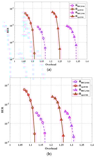
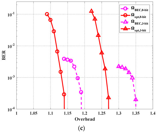
Figure 7.
Bit error rate (BER) performance with the optimized profiles and benchmark profile for the cases of the three-bit quantizer and the eight-bit quantizer under different channel matrices: (a) , (b) , and (c) .
(2) Throughout performance
We simulate the average sum throughput under different SNRs. We fix but change the transmission power for different SNRs. For each SNR, we optimize the degree profiles of the two users for both three-bit and eight-bit quantizer cases. Figure 8 shows the simulation results. For each point in the figure, we simulate 100 rounds of transmission, and the channel matrix is uniformly and randomly chosen from , and in each round. As can be seen in Figure 7, the optimized degree profile achieves a higher throughput compared with the BEC profile. The performance of the eight-bit quantization case with the optimized degree profiles is within only 11% away from the theoretical limit. Here, the theoretical limit is the upper bound of the average theoretically achievable sum rate, which is calculated by
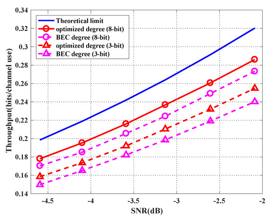
Figure 8.
Achieved throughput with the optimized profiles and benchmark profile for the cases of the three-bit quantizer and the eight-bit quantizer.
6. Conclusions
We considered the rateless coded transmission scheme for two-user uplink in C-RAN with two RRHs under a block fading channel. In the proposed scheme, both users keep transmitting until the BBU pool feeds back ACKs, where instant CSI is not required by the users. We also proposed a scheme to find the universally good degree profiles for both users under all possible channel states, with only statistics information of the channel matrix. In detail, the degree profiles are optimized to minimize the threshold SNR under the conditions that the average code length is fixed and the message of each user can be correctly recovered at the BBU pool in all possible channel states. It can be seen from the simulation that the optimized degree profiles have better performance for both BER and system throughput, compared with the BEC profile. Moreover, the achieved throughput has only about 11% loss from the theoretical limit.
Note that although only a two-user case is considered in this paper, the extension to the multi-user case is not difficult. One can simply extend the iterative receiver structure in Figure 2, where the output LLR of the MU detector can be calculated accordingly. Using EXIT analysis, the degree profile optimization problem can also be formulated, and DE can be applied.
Author Contributions
Conceptualization, Y.Z. and Z.Z.; Computer simulation, J.X.; Formal analysis, J.X. and Y.Z.; Data curation, W.L.; Investigation, J.X. and H.P.; Writing-original draft, Y.Z. and J.X.; Writing-review & editing, Y.Z. and J.X.
Funding
This research was funded in part by the Zhejiang Provincial Natural Science Foundation of China under Grant LY17F010014, the National Natural Science Foundation of China (No. 61871348, No. 61871349, No. 61803336), and by the open project of Zhejiang Provincial Key Laboratory of Information Processing, Communication and Networking, Zhejiang, China.
Conflicts of Interest
The authors declare no conflict of interest.
References
- Singh, S.; Singh, N. Internet of Things (IoT): Security Challenges, Business Opportunities & Reference Architecture for E-Commerce. In Proceedings of the 2015 International Conference on Green Computing & Internet of Things, Noida, India, 8–10 October 2015. [Google Scholar]
- Torchia, M.K.M. IDC’s Worldwide Internet of Things Connectivity Taxonomy; IDC Corp: Framingham, MA, USA, 2017. [Google Scholar]
- Miyanabe, K.; Rodrigues, T.G.; Lee, Y.; Nishiyama, H.; Kato, N. An Internet of Things Traffic-Based Power Saving Scheme in Cloud-Radio Access Network. IEEE Internet Things J. 2018, 6, 1. [Google Scholar] [CrossRef]
- Yao, J.J.; Ansari, N. Joint content placement and storage allocation in C-RANs for IoT sensing service. IEEE Internet Things J. 2019, 6, 1060–1067. [Google Scholar] [CrossRef]
- Mouawad, M.; Dziong, Z.; El-Ashmawy, A. Load Balancing in 5G C-RAN Based on Dynamic BBU-RRH Mapping Supporting IoT Communications. In Proceedings of the 2018 IEEE Global Conference on Internet of Things, Alexandria, Egypt, 5–7 December 2018. [Google Scholar]
- Lu, W.D.; Hu, S.; Liu, X.; He, C.X.; Gong, Y. Incentive Mechanism Based Cooperative Spectrum Sharing for OFDM Cognitive IoT Network. IEEE Trans. Netw. Sci. Eng. 2019, 1. [Google Scholar] [CrossRef]
- Checko, A.; Christiansen, H.L.; Yan, Y.; Scolari, L. Cloud RAN for Mobile Networks—A Technology Overview. IEEE Commun. Surv. Tutor. 2015, 17, 405–426. [Google Scholar] [CrossRef]
- Wu, J.; Zhang, Z.F.; Hong, Y.; Wen, Y. Cloud Radio Access Network (C-RAN): A Primer. IEEE Netw. 2015, 29, 35–41. [Google Scholar] [CrossRef]
- Park, S.H.; Simeone, O.; Sahin, O.; Shitz, S.S. Fronthaul Compression for Cloud Radio Access Networks: Signal processing advances inspired by network information theory. IEEE Signal Process. Mag. 2014, 31, 69–79. [Google Scholar] [CrossRef]
- Kang, J.; Simeone, O.; Kang, J.; Shitz, S.S. Joint Signal and Channel State Information Compression for the Backhaul of Uplink Network MIMO Systems. IEEE Trans. Wirel. Commun. 2013, 13, 1555–1567. [Google Scholar] [CrossRef]
- Zhou, Y.; Yu, W. Fronthaul Compression and Transmit Beamforming Optimization for Multi-Antenna Uplink C-RAN. IEEE Trans. Signal Process. 2016, 64, 4138–4151. [Google Scholar] [CrossRef]
- Park, S.H.; Simeone, O.; Sahin, O.; Shamai, S. Joint Precoding and Multivariate Backhaul Compression for the Downlink of Cloud Radio Access Networks. IEEE Trans. Signal Process. 2013, 61, 5646–5658. [Google Scholar] [CrossRef]
- Marotta, M.A.; Ahmadi, H.; Rochol, J.; DaSilva, L.; Both, C.B. Characterizing the Relation Between Processing Power and Distance Between BBU and RRH in A Cloud RAN. IEEE Wirel. Commun. Lett. 2018, 7, 472–475. [Google Scholar] [CrossRef]
- Shokrollahi, A. Raptor codes. IEEE Trans. Inf. Theory 2006, 52, 2551–2567. [Google Scholar] [CrossRef]
- Castura, J.; Mao, Y.Y. Rateless Coding Over Fading Channels. IEEE Commun. Lett. 2006, 10, 46–48. [Google Scholar] [CrossRef]
- Wubben, D.; Rost, P.; Bartelt, J.S.; Lalam, M.; Savin, V.; Gorgoglione, M.; Dekorsy, A.; Fettweis, G. Benefits and Impact of Cloud Computing on 5G Signal Processing: Flexible centralization through cloud-RAN. IEEE Signal Process. Mag. 2014, 31, 35–44. [Google Scholar] [CrossRef]
- Park, S.; Chae, C.B.; Bahk, S. Large-scale antenna operation in heterogeneous cloud radio access networks: A partial centralization approach. IEEE Wirel. Commun. 2015, 22, 32–40. [Google Scholar] [CrossRef]
- Dotsch, U.; Doll, M.; Mayer, H.P.; Schaich, F.; Segel, J.; Sehier, P. Quantitative analysis of split base station processing and determination of advantageous architectures for LTE. Bell Labs Tech. J. 2013, 18, 105–128. [Google Scholar] [CrossRef]
- Shi, Y.; Zhang, J.; Letaief, K.B.; Bai, B.; Chen, W. Large-scale convex optimization for ultra-dense cloud-RAN. IEEE Wirel. Commun. 2015, 22, 84–91. [Google Scholar] [CrossRef]
- Park, S.H.; Simeone, O.; Shamai, S. Joint Optimization of Cloud and Edge Processing for Fog Radio Access Networks. IEEE Trans. Wirel. Commun. 2016, 15, 7621–7632. [Google Scholar] [CrossRef]
- Vien, Q.T.; Le, T.A.; Barn, B.; Phan, C. Optimising Energy Efficiency of NOMA for Wireless Backhaul in Heterogeneous CRAN. IET Commun. 2016, 10, 2516–2524. [Google Scholar] [CrossRef]
- Tran, H.Q.; Truong, P.Q.; Phan, C.V.; Vien, Q.T. On the Energy Efficiency of NOMA for Wireless Backhaul in Multi-Tier Heterogeneous CRAN. In Proceedings of the 2017 International Conference on Recent Advances in Signal Processing, Telecommunications & Computing (SigTelCom), Da Nang, Vietnam, 9–11 Jane 2017. [Google Scholar]
- Chen, G.J.; Yang, F.L.; Niu, K.; Dong, C. Linear Predictive Coding Based Compression Algorithm for Fronthaul Link in C-RAN. In Proceedings of the 2017 IEEE/CIC International Conference on Communications in China, Qingdao, China, 22–24 October 2017. [Google Scholar]
- Kang, J.; Simeone, O.; Kang, J.; Shamai, S. Layered Downlink Precoding for C-RAN Systems with Full Dimensional MIMO. IEEE Trans. Veh. Technol. 2016, 66, 2170–2182. [Google Scholar] [CrossRef]
- He, Z.; Hu, C.; Peng, T.; Ma, C. A compression scheme for LTE baseband signal in C-RAN. In Proceedings of the International Conference on Communications & Networking in China, Shanghai, China, 14–16 August 2014. [Google Scholar]
- Kang, J.; Simeone, O.; Kang, J.; Shamai, S. Fronthaul Compression and Precoding Design for C-RANs over Ergodic Fading Channels. IEEE Trans. Veh. Technol. 2015, 65, 5022–5032. [Google Scholar] [CrossRef]
- Jeon, Y.; Park, S.H.; Song, C.; Moon, J.; Maeng, S.; Lee, I. Joint Designs of Fronthaul Compression and Precoding for Full-Duplex Cloud Radio Access Networks. IEEE Wirel. Commun. Lett. 2016, 5, 632–635. [Google Scholar] [CrossRef]
- Kang, J.; Simeone, O.; Kang, J.; Shamai, S. Joint Precoding and Fronthaul Optimization for C-Rans in Ergodic Fading Channels. In Proceedings of the IEEE International Conference on Communication Workshop, London, UK, 8–12 June 2015. [Google Scholar]
- Wang, G.; Wu, M.; Sun, Y.; Cavallaro, J.R. GPU Accelerated Scalable Parallel Decoding of LDPC Codes. In Proceedings of the 2011 Conference Record of the Forty Fifth Asilomar Conference on Signals, Systems and Computers, Pacific Grove, CA, USA, 6–9 November 2011. [Google Scholar]
- Wübben, D.; Paul, H.; Balleydier, P.; Savin, V.; Rost, P. Decoder Implementation for Cloud Based Architectures. In Proceedings of the Proc. European Conference on Networks and Commun, Bologna, Italy, 23–26 June 2014. [Google Scholar]
- Wubben, D.; Paul, H. Analysis of Virtualized Turbo-decoder Implementation for Cloud-RAN Systems. In Proceedings of the 2016 9th International Symposium on Turbo Codes and Iterative Information Processing, Brest, France, 5–9 September 2016. [Google Scholar]
- Luby, M.; Watson, M.; Gasiba, T.; Stockhammer, T.; Xu, W. Raptor Codes for Reliable Download Delivery in Wireless Broadcast Systems. In Proceedings of the IEEE Consumer Communications and Networking Conference, Las Vegas, NV, USA, 8–10 January 2006. [Google Scholar]
- Chen, X.M.; Zhang, Z.Y.; Chen, S.L.; Wang, C. Adaptive Mode Selection for Multiuser MIMO Downlink Employing Rateless Codes with Qos Provisioning. IEEE Trans. Wirel. Commun. 2012, 11, 790–799. [Google Scholar] [CrossRef]
- Chen, X.M.; Yuen, C. Efficient Resource Allocation in Rateless Coded MU-MIMO Cognitive Radio Network with Qos Provisioning and Limited Feedback. IEEE Trans. Veh. Technol. 2013, 62, 395–399. [Google Scholar] [CrossRef]
- Zhang, Y.; Zhang, Z.Y. Joint Network-Channel Coding with Rateless Code Over Multiple Access Relay System. IEEE Trans. Wirel. Commun. 2013, 12, 320–332. [Google Scholar] [CrossRef]
- Zhang, Y.; Zhang, Z.Y.; Yin, R.; Yu, G.D.; Wang, W. Joint Network-Channel Coding with Rateless Code in Two-Way Relay Systems. IEEE Trans. Wirel. Commun. 2013, 12, 3158–3169. [Google Scholar] [CrossRef]
- Zhang, Y.; Zhang, Y.F.; Peng, H.; Xie, L.J.; Meng, L.M. Rateless Coded Multi-user Downlink Transmission in Cloud Radio Access Network. In Mobile Networks and Applications; Springer: New York, NY, USA, 2018. [Google Scholar]
- Xie, L.J.; Zhang, Y.; Zhang, Y.F.; Hua, J.Y.; Meng, L.M. Uplink Transmission Scheme Based on Rateless Coding in Cloud-RAN. In Proceedings of the International Conference on Machine Learning and Intelligent Communications, Hangzhou, China, 12 October 2018. [Google Scholar]
- Zhang, Y.; Xu, J.L.; Peng, H.; Lu, W.D.; Hua, J.Y. Rateless Code Profiles Design for Uplink C-RAN under Block Fading Channel. In Proceedings of the 10th International Conference on Wireless Communications and Signal Processing, Hangzhou, China, 18–20 October 2008. [Google Scholar]
- Pukelsheim, F. The Three Sigma Rule. Am. Stat. 1994, 48, 88–91. [Google Scholar] [CrossRef]
- Venkiah, A.; Poulliat, C.; Declercq, D. Analysis and Design of Raptor Codes for Joint Decoding Using Information Content Evolution. IEEE Int. Symp. Inform. Theory 2007, 421–425. [Google Scholar] [CrossRef]
- Auguste, V.; Charly, P.; David, D. Jointly Decoded Raptor Codes: Analysis and Design for the Biawgn Channel. EURASIP J. Wirel. Commun. Netw. 2009, 2009, 657970. [Google Scholar] [CrossRef]
- Etesami, O.; Shokrollahi, A. Raptor Codes on Binary Memoryless Symmetric Channels. IEEE Trans. Inf. Theory 2006, 52, 2033–2051. [Google Scholar] [CrossRef]
- Chen, G.; Yue, G.S.; Wang, X.D. Analysis and Optimization of a Rateless Coded Joint Relay System. IEEE Trans. Wirel. Commun. 2010, 9, 1175–1185. [Google Scholar]
- Venkiah, A.; Piantanida, P.; Poullia, C.; Declercq, D. Rateless Coding for Quasi-Static Fading Channels Using Channel Estimation Accuracy. IEEE Int. Symp. Inform. Theory 2008, 2257–2261. [Google Scholar] [CrossRef]
- Storn, R.; Price, K. Differential evolution: A simple and efficient heuristic for global optimization over continuous spaces. J. Glob. Optim. 1997, 11, 341–359. [Google Scholar] [CrossRef]
© 2019 by the authors. Licensee MDPI, Basel, Switzerland. This article is an open access article distributed under the terms and conditions of the Creative Commons Attribution (CC BY) license (http://creativecommons.org/licenses/by/4.0/).