A Multi-Antenna Scheme for Early Detection and Mitigation of Intermediate GNSS Spoofing


Abstract
1. Introduction
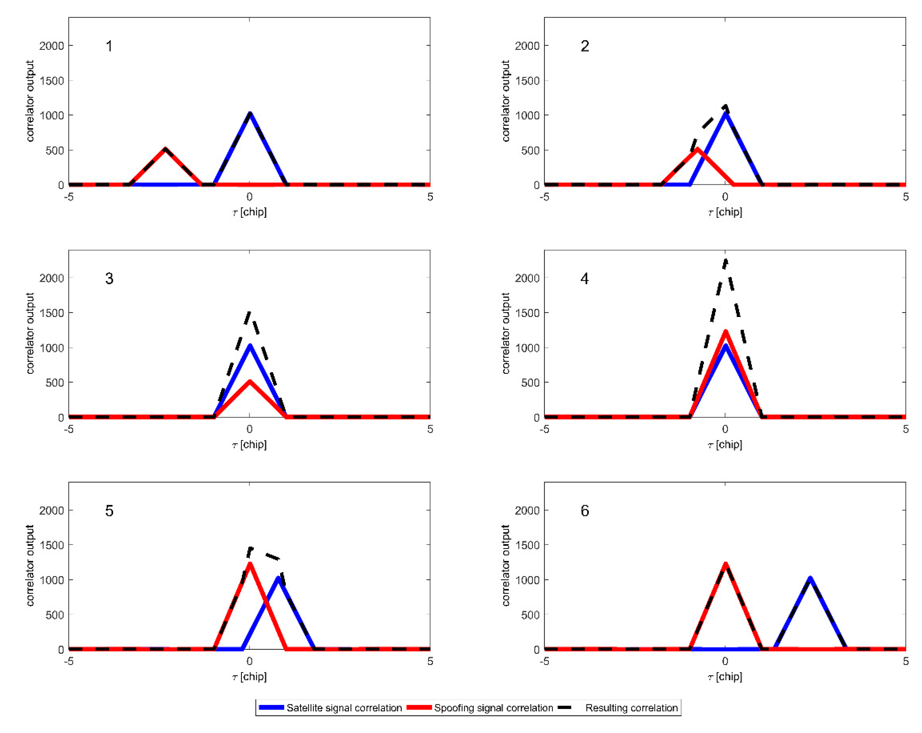
2. Intermediate GNSS spoofing Signal Model
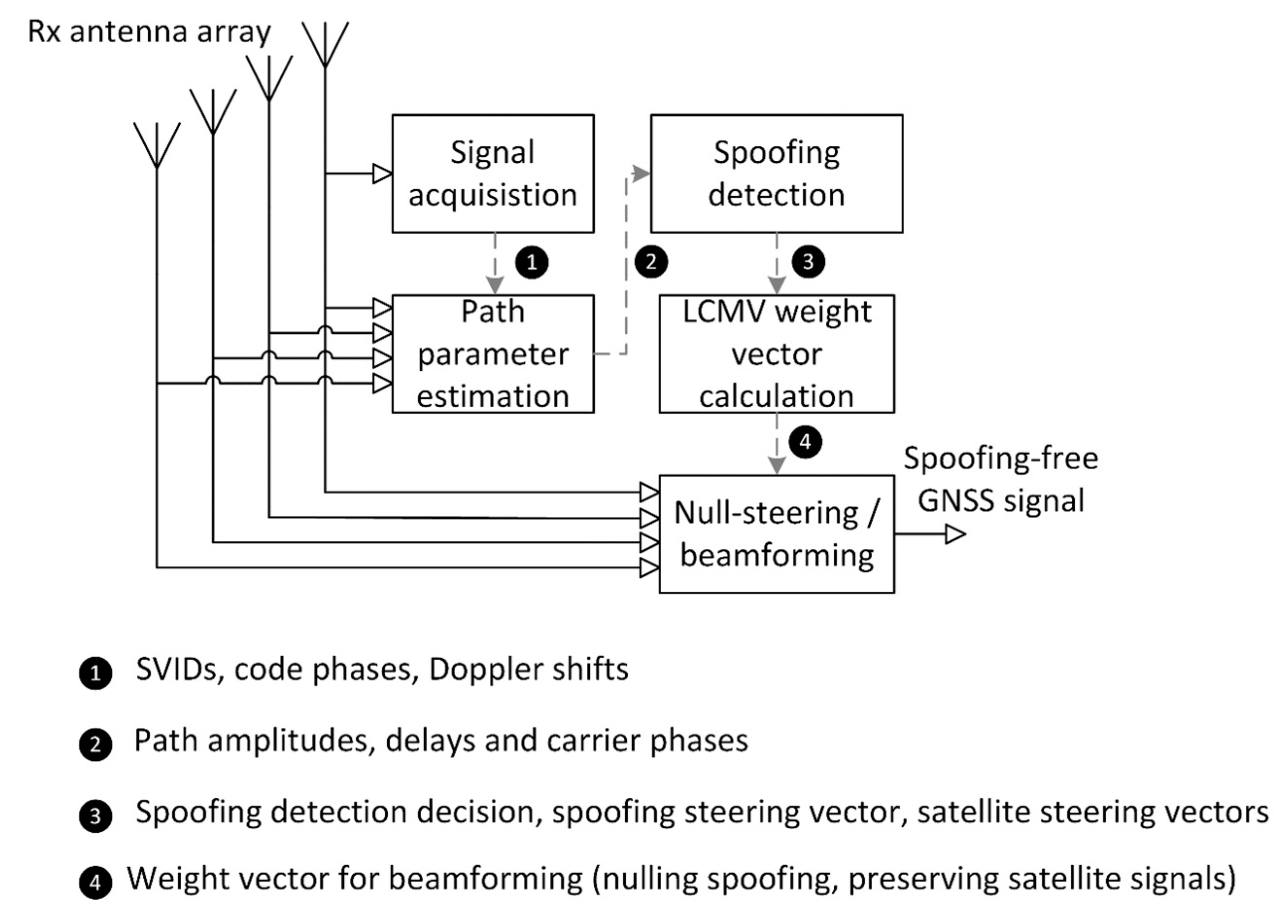
3. Early Detection and Mitigation of Spoofing
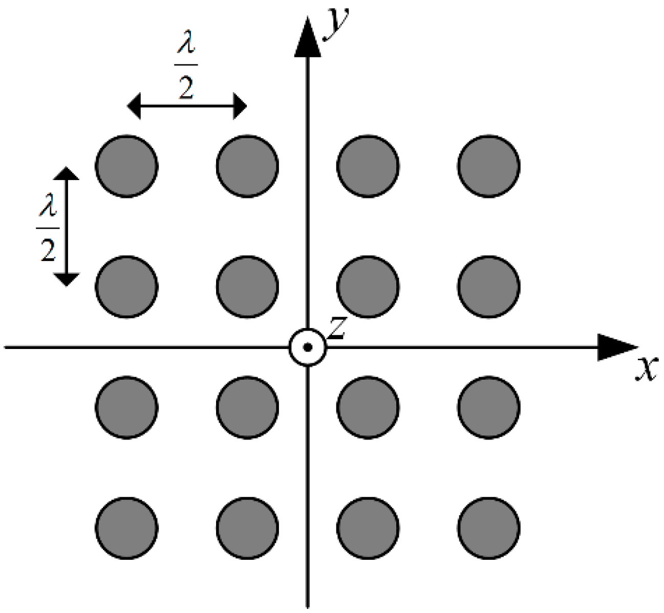
3.1. Steering Vector Estimation
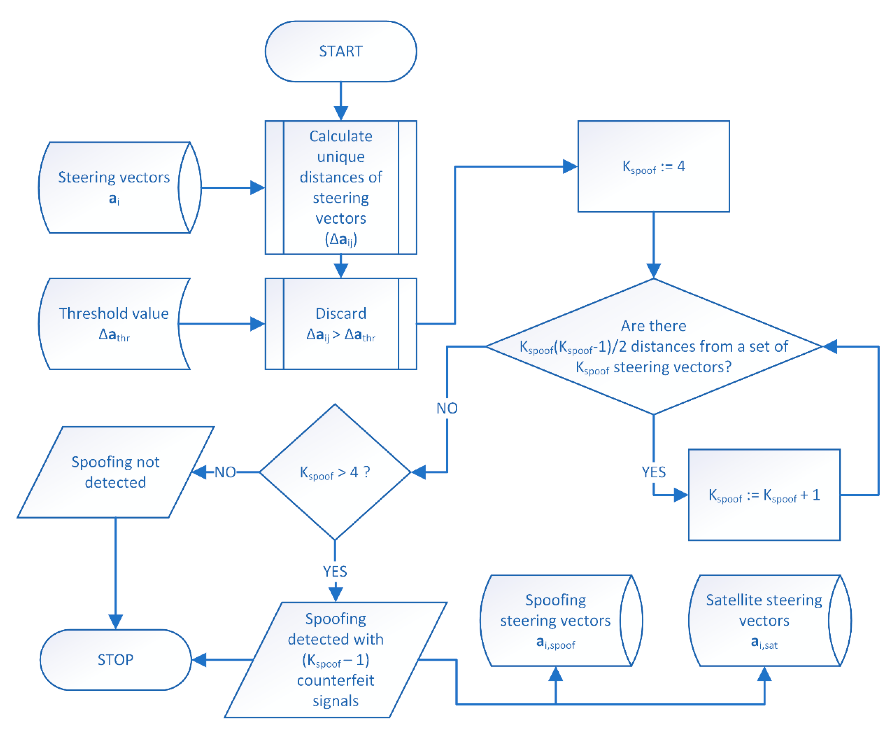
3.2. Spoofing Detection
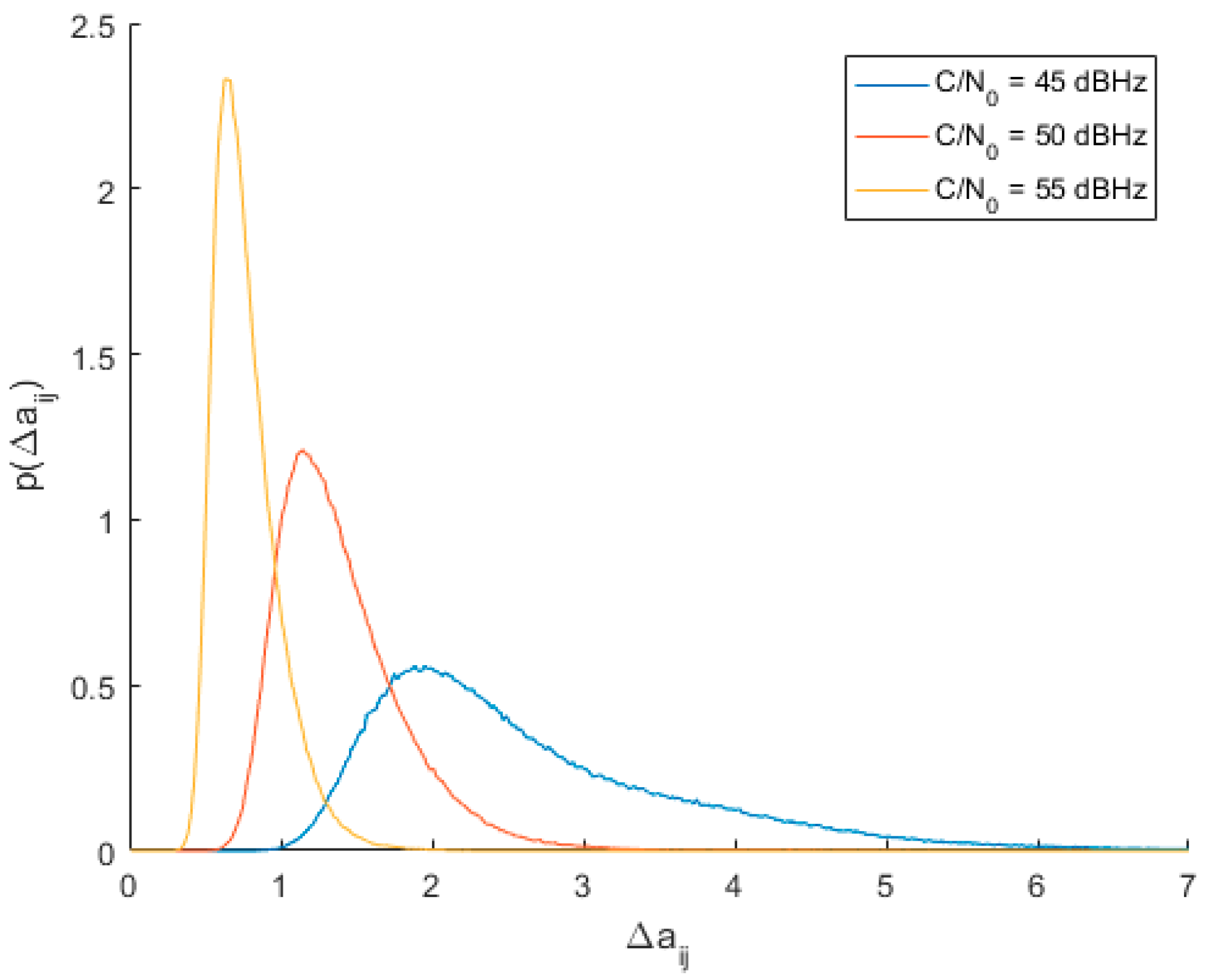
3.3. Determining Optimal Spoofing Detection Threshold
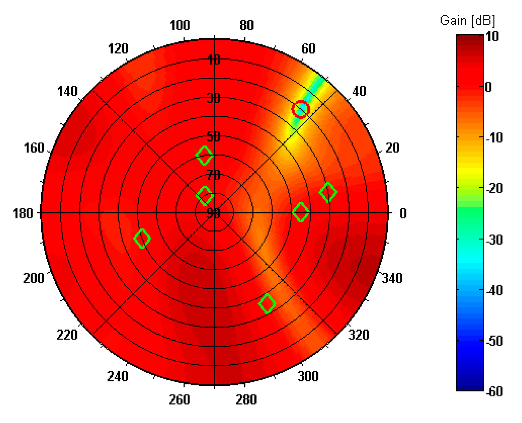
3.4. Spoofing Mitigation
4. Simulation Results
4.1. Evaluation of Detection Threshold
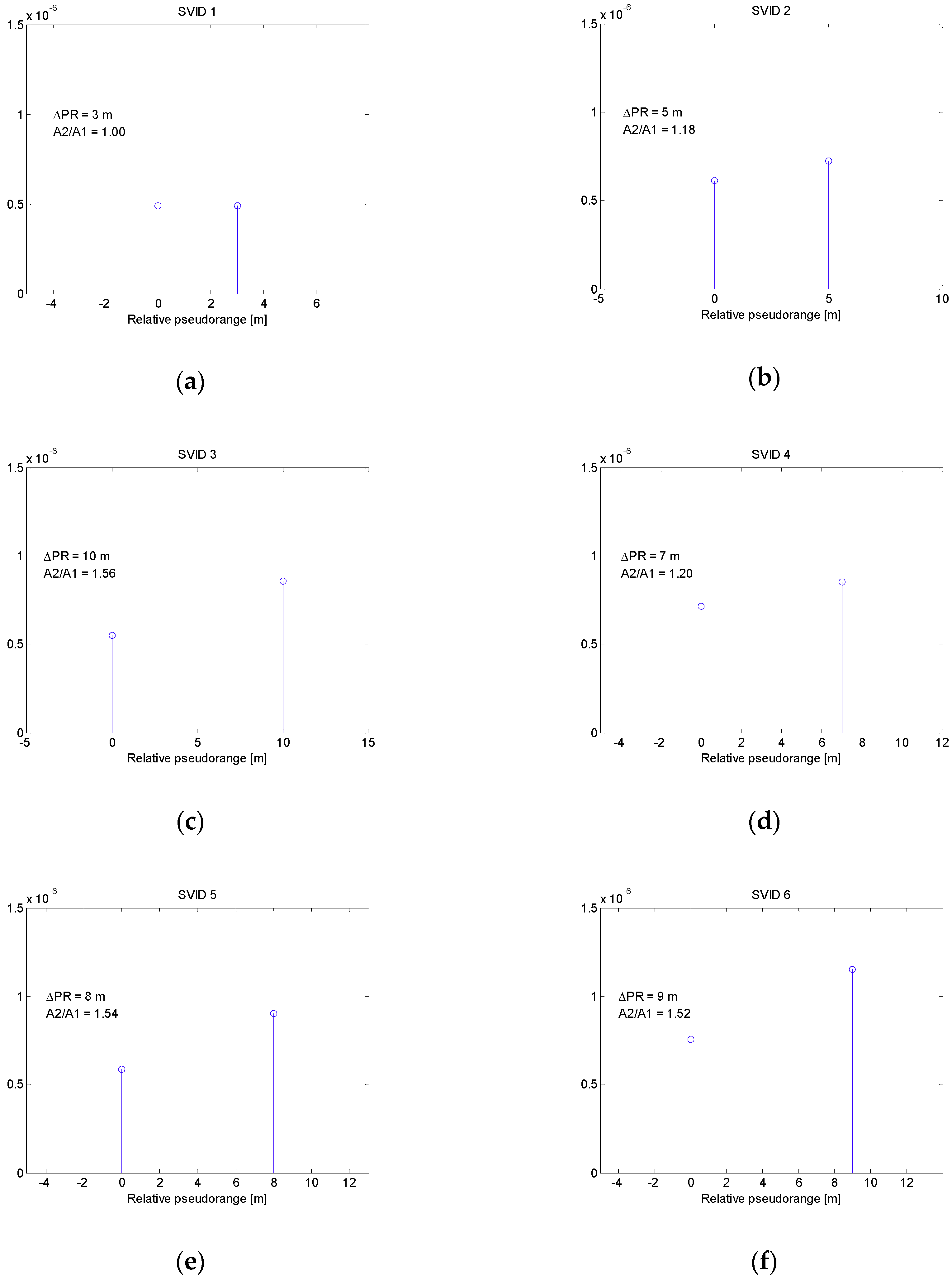
4.2. Spoofing Scenario 1
4.3. Spoofing Scenario 2
5. Conclusions
Funding
Conflicts of Interest
References
- Ioannides, R.T.; Pany, T.; Gibbons, G. Known Vulnerabilities of Global Navigation Satellite Systems, Status, and Potential Mitigation Techniques. Proc. IEEE 2016, 104, 1174–1194. [Google Scholar] [CrossRef]
- Warner, J.S.; Johnston, R.G. GPS spoofing countermeasures. Homeland Secur. J. 2003, 25, 19–27. [Google Scholar]
- Jafarnia-Jahromi, A.; Broumandan, A.; Nielsen, J.; Lachapelle, G. GPS Vulnerability to Spoofing Threats and a Review of Antispoofing Techniques. Int. J. Navig. Obs. 2012, 2012, 127072. [Google Scholar] [CrossRef]
- Wen, H.Q.; Huang, P.Y.-R.; Dyer, J.; Archinal, A.; Fagan, J. Countermeasures for GPS Signal Spoofing. In Proceedings of the 18th International Technical Meeting of the Satellite Division of the Institute of Navigation (ION GNSS 2005), Long Beach, CA, USA, 13–16 September 2005. [Google Scholar]
- Dampf, J.; Pany, T.; Bär, W.; Winkel, J.; Mervart, L.; Ávila-Rodríguez, J.; Ioannides, R.; Hein, G. Real World Spoofing Trials and Mitigation. InsideGNSS 2017, 12, 55–65. [Google Scholar]
- Humphreys, T.E.; Ledvina, B.M.; Psiaki, M.L.; O’Hanlon, B.W.; Kintner, P.M., Jr. Assessing the Spoofing Threat: Development of a Portable GPS Civilian Spoofer. In Proceedings of the 21st International Technical Meeting of the Satellite Division of The Institute of Navigation (ION GNSS 2008), Savannah, GA, USA, 16–18 September 2008. [Google Scholar]
- Psiaki, M.L.; Humphreys, T.E. GNSS Spoofing and Detection. Proc. IEEE 2016, 104, 1258–1270. [Google Scholar] [CrossRef]
- Huang, J.; Lo Presti, L.; Motella, B.; Pini, M. GNSS spoofing detection: Theoretical analysis and performance of the Ratio Test metric in open sky. ICT Express 2016, 2, 37–40. [Google Scholar] [CrossRef]
- Nielsen, J.; Broumandan, A.; Lachapelle, G. Spoofing Detection and Mitigation with a Moving Handheld Receiver. GPS World 2010, 21, 27–33. [Google Scholar]
- Psiaki, M.L.; Powell, S.P.; O’Hanlon, B.W. GNSS Spoofing Detection using High-Frequency Antenna Motion and Carrier-Phase Data. In Proceedings of the 26th International Technical Meeting of the Satellite Division of The Institute of Navigation (ION GNSS+ 2013), Nashville, TN, USA, 16–20 September 2013; pp. 2949–2991. [Google Scholar]
- Psiaki, M.L.; OHanlon, B.W.; Powell, S.P.; Bhatti, J.A.; Wesson, K.D.; Humphreys, T.E.; Schofield, A. GNSS Spoofing Detection Using Two-Antenna Differential Carrier Phase. In Proceedings of the 27th International Technical Meeting of the Satellite Division of The Institute of Navigation (ION GNSS+ 2014), Tampa, FL, USA, 8–12 September 2014; pp. 2776–2800. [Google Scholar]
- Borio, D.; Gioia, C. A sum-of-squares approach to GNSS spoofing detection. IEEE Trans. Aerosp. Electron. Syst. 2016, 52, 1756–1768. [Google Scholar] [CrossRef]
- Konovaltsev, A.; Caizzone, S.; Cuntz, M.; Meurer, M. Autonomous Spoofing Detection and Mitigation with a Miniaturized Adaptive Antenna Array. In Proceedings of the 27th International Technical Meeting of the Satellite Division of The Institute of Navigation (ION GNSS+ 2014), Tampa, FL, USA, 8–12 September 2014; pp. 2853–2861. [Google Scholar]
- Daneshmand, S.; Jafarnia-Jahromi, A.; Broumandan, A.; Lachapelle, G. A Low-Complexity GPS Anti-Spoofing Method Using a Multi-Antenna Array. In Proceedings of the 25th International Technical Meeting of the Satellite Division of The Institute of Navigation (ION GNSS 2012), Nashville, TN, USA, 17–21 September 2012; pp. 1233–1243. [Google Scholar]
- Daneshmand, S.; Jafarnia-Jahromi, A.; Broumandan, A.; Lachapelle, G. A GNSS structural interference mitigation technique using antenna array processing. In Proceedings of the 2014 IEEE 8th Sensor Array and Multichannel Signal Processing Workshop (SAM), A Coruna, Spain, 22–25 June 2014; pp. 109–112. [Google Scholar]
- Magiera, J.; Katulski, R. Accuracy of differential phase delay estimation for GPS spoofing detection. In Proceedings of the 36th International Conference on Telecommunications and Signal Processing (TSP), Rome, Italy, 2–4 July 2013; pp. 695–699. [Google Scholar]
- Magiera, J.; Katulski, R. Applicability of Null-Steering for Spoofing Mitigation in Civilian GPS. In Proceedings of the IEEE 79th Vehicular Technology Conference (VTC Spring), Seoul, Korea, 18–21 May 2014. [Google Scholar]
- Sahmoudi, M.; Landry, R. Multipath Mitigation Techniques using Maximum-Likelihood Principle. InsideGNSS 2008, 3, 24–29. [Google Scholar]
- Weill, L.R. Multipath Mitigation using Modernized GPS Signals: How Good Can it Get? In Proceedings of the 15th International Technical Meeting of the Satellite Division of the Institute of Navigation (ION GPS 2002), Portland, OR, USA, 24–27 September 2002; pp. 493–505. [Google Scholar]
- Parkinson, B.W.; Axelrad, P. Autonomous GPS integrity monitoring using the pseudorange residual. Navigation 1988, 35, 255–274. [Google Scholar] [CrossRef]
- Capon, J. High-resolution frequency-wavenumber spectrum analysis. Proc. IEEE 1969, 57, 1408–1418. [Google Scholar] [CrossRef]
- Frost, O.L. An algorithm for linearly constrained adaptive array processing. Proc. IEEE 1972, 60, 926–935. [Google Scholar] [CrossRef]
- Chen, X.; Dovis, F.; Peng, S.; Morton, Y. Comparative Studies of GPS Multipath Mitigation Methods Performance. IEEE Trans. Aerosp. Electron. Syst. 2013, 49, 1555–1568. [Google Scholar] [CrossRef]


| C/N0 | Δathr,max | C/N0 | Δathr,max |
|---|---|---|---|
| 45 | 3.6 | 51 | 3.7 |
| 46 | 3.6 | 52 | 3.8 |
| 47 | 3.6 | 53 | 3.8 |
| 48 | 3.6 | 54 | 4.0 |
| 49 | 3.6 | 55 | 4.0 |
| 50 | 3.6 |
| C/N0 | Pd | C/N0 | Pd |
|---|---|---|---|
| 45 | 46.9% | 51 | 99.9% |
| 46 | 57.9% | 52 | > 99.9% |
| 47 | 74.4% | 53 | > 99.9% |
| 48 | 83.5% | 54 | > 99.9% |
| 49 | 97.2% | 55 | > 99.9% |
| 50 | 99.2% |
| SVID | ϕsat [°] | θsat [°] | C/N0 [dBHz] |
|---|---|---|---|
| 1 | 300 | 35 | 47 |
| 2 | 0 | 45 | 48 |
| 3 | 200 | 50 | 49 |
| 4 | 100 | 60 | 50 |
| 5 | 120 | 80 | 51 |
| 6 | 10 | 30 | 52 |
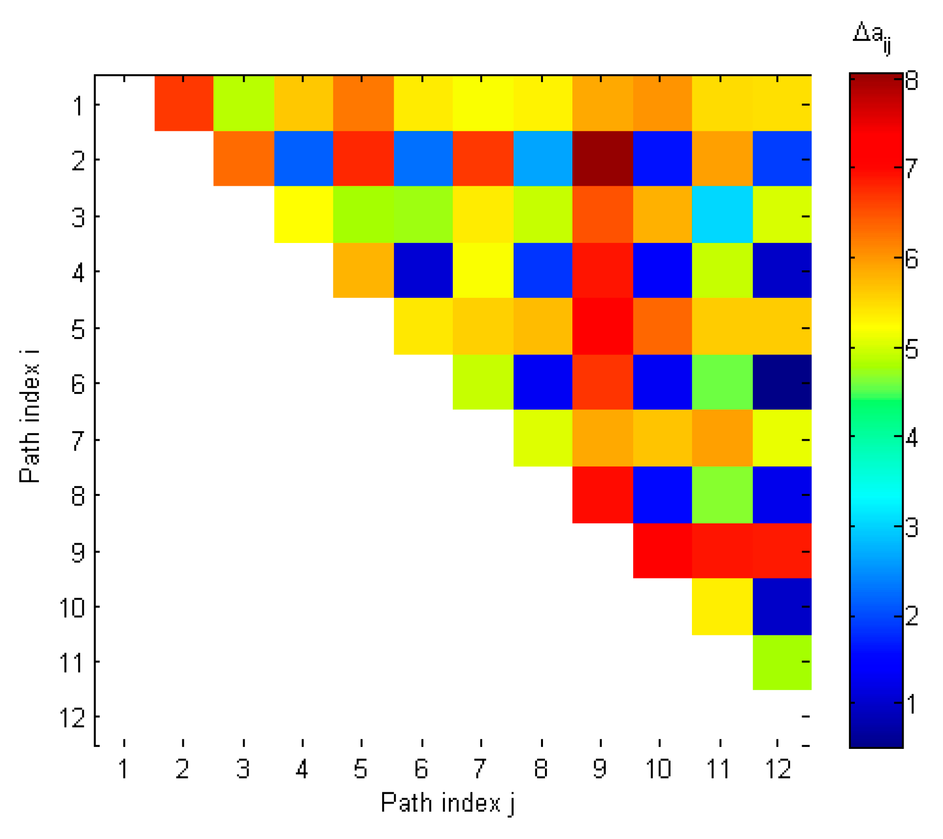
| i,j | 2 | 3 | 4 | 5 | 6 | 7 | 8 | 9 | 10 | 11 | 12 |
|---|---|---|---|---|---|---|---|---|---|---|---|
| 1 | 6.62 | 4.83 | 5.60 | 6.19 | 5.35 | 5.16 | 5.29 | 5.83 | 5.99 | 5.45 | 5.42 |
| 2 | 6.27 | 2.14 | 6.76 | 2.26 | 6.64 | 2.64 | 8.03 | 1.62 | 5.89 | 1.92 | |
| 3 | 5.18 | 4.75 | 4.71 | 5.35 | 4.89 | 6.46 | 5.77 | 3.01 | 5.00 | ||
| 4 | 5.75 | 1.10 | 5.17 | 1.83 | 6.85 | 1.38 | 4.90 | 1.01 | |||
| 5 | 5.37 | 5.55 | 5.69 | 7.17 | 6.31 | 5.58 | 5.58 | ||||
| 6 | 4.90 | 1.31 | 6.67 | 1.31 | 4.55 | 0.51 | |||||
| 7 | 5.02 | 5.85 | 5.65 | 5.90 | 5.08 | ||||||
| 8 | 6.94 | 1.55 | 4.63 | 1.27 | |||||||
| 9 | 7.33 | 6.88 | 6.83 | ||||||||
| 10 | 5.30 | 1.01 | |||||||||
| 11 | 4.74 |
| i,j | 2 | 3 | 4 | 5 | 6 | 7 | 8 | 9 | 10 | 11 | 12 |
|---|---|---|---|---|---|---|---|---|---|---|---|
| 1 | 4.64 | 5.82 | 5.54 | 6.05 | 5.19 | 4.88 | 5.20 | 5.76 | 5.00 | 5.91 | 5.05 |
| 2 | 5.34 | 1.69 | 6.58 | 1.30 | 1.01 | 1.11 | 4.18 | 3.64 | 4.61 | 4.86 | |
| 3 | 6.25 | 5.57 | 5.52 | 5.49 | 5.72 | 6.06 | 5.20 | 5.85 | 3.52 | ||
| 4 | 7.45 | 1.21 | 1.26 | 1.07 | 4.82 | 3.90 | 4.99 | 5.58 | |||
| 5 | 7.09 | 6.77 | 7.20 | 7.97 | 6.90 | 7.39 | 5.39 | ||||
| 6 | 1.00 | 0.70 | 4.54 | 3.26 | 4.77 | 4.96 | |||||
| 7 | 0.98 | 4.22 | 3.37 | 4.56 | 4.89 | ||||||
| 8 | 4.40 | 3.62 | 4.69 | 5.22 | |||||||
| 9 | 5.08 | 3.07 | 5.46 | ||||||||
| 10 | 5.29 | 3.82 | |||||||||
| 11 | 4.92 |
© 2019 by the author. Licensee MDPI, Basel, Switzerland. This article is an open access article distributed under the terms and conditions of the Creative Commons Attribution (CC BY) license (http://creativecommons.org/licenses/by/4.0/).
Share and Cite
Magiera, J. A Multi-Antenna Scheme for Early Detection and Mitigation of Intermediate GNSS Spoofing. Sensors 2019, 19, 2411. https://doi.org/10.3390/s19102411
Magiera J. A Multi-Antenna Scheme for Early Detection and Mitigation of Intermediate GNSS Spoofing. Sensors. 2019; 19(10):2411. https://doi.org/10.3390/s19102411
Chicago/Turabian StyleMagiera, Jaroslaw. 2019. "A Multi-Antenna Scheme for Early Detection and Mitigation of Intermediate GNSS Spoofing" Sensors 19, no. 10: 2411. https://doi.org/10.3390/s19102411
APA StyleMagiera, J. (2019). A Multi-Antenna Scheme for Early Detection and Mitigation of Intermediate GNSS Spoofing. Sensors, 19(10), 2411. https://doi.org/10.3390/s19102411