Force Modeling, Identification, and Feedback Control of Robot-Assisted Needle Insertion: A Survey of the Literature


Abstract
:1. Introduction
1.1. Background
1.2. Related Work
1.3. Aims and Methods
2. Methods of Needle Insertion Force Modeling
2.1. Stiffness Force Modeling
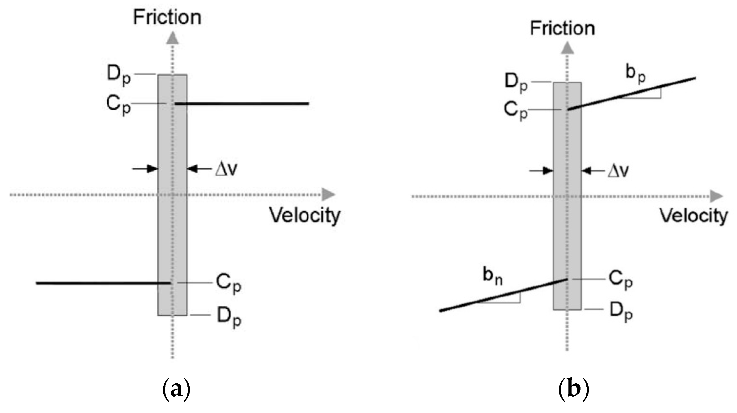
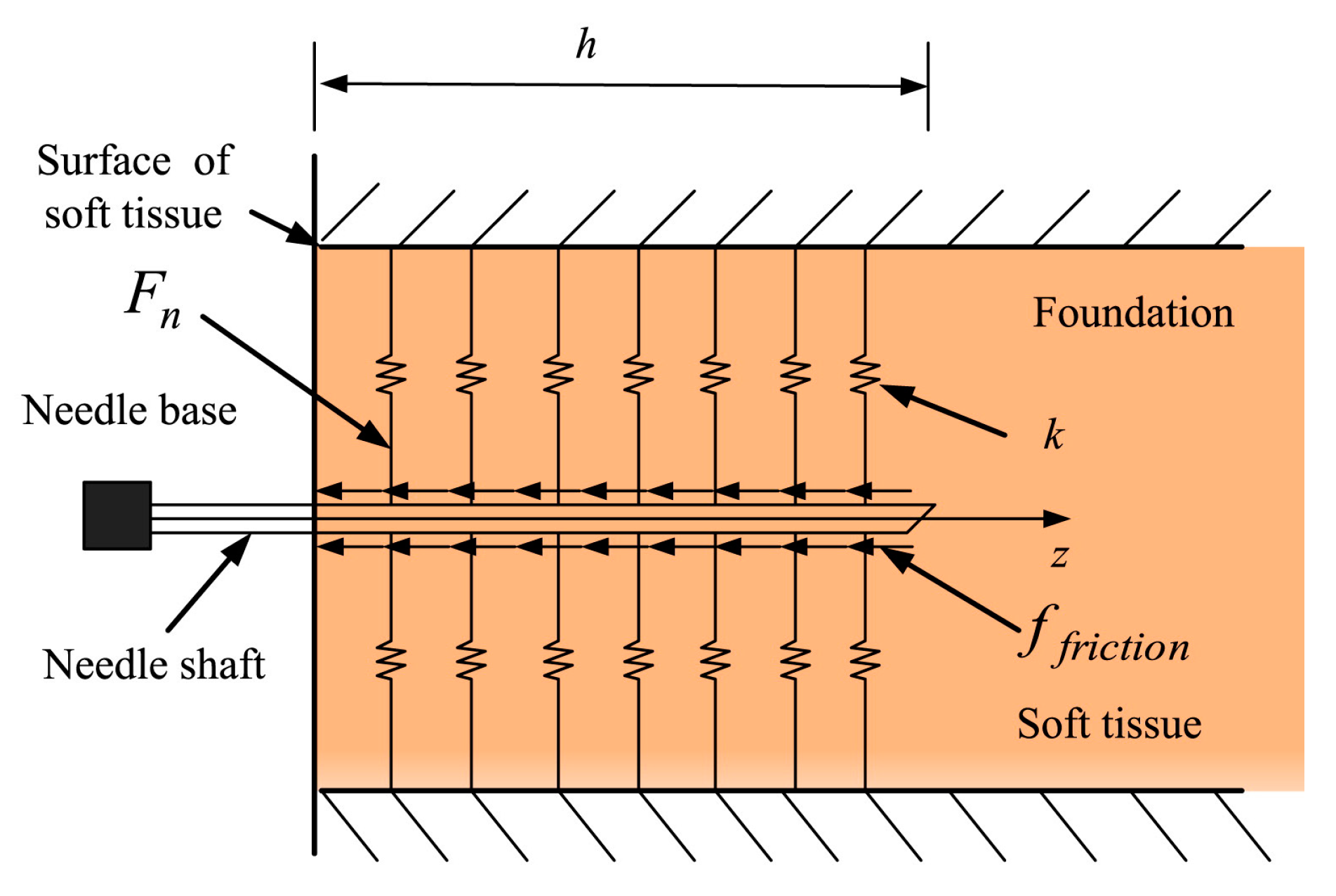
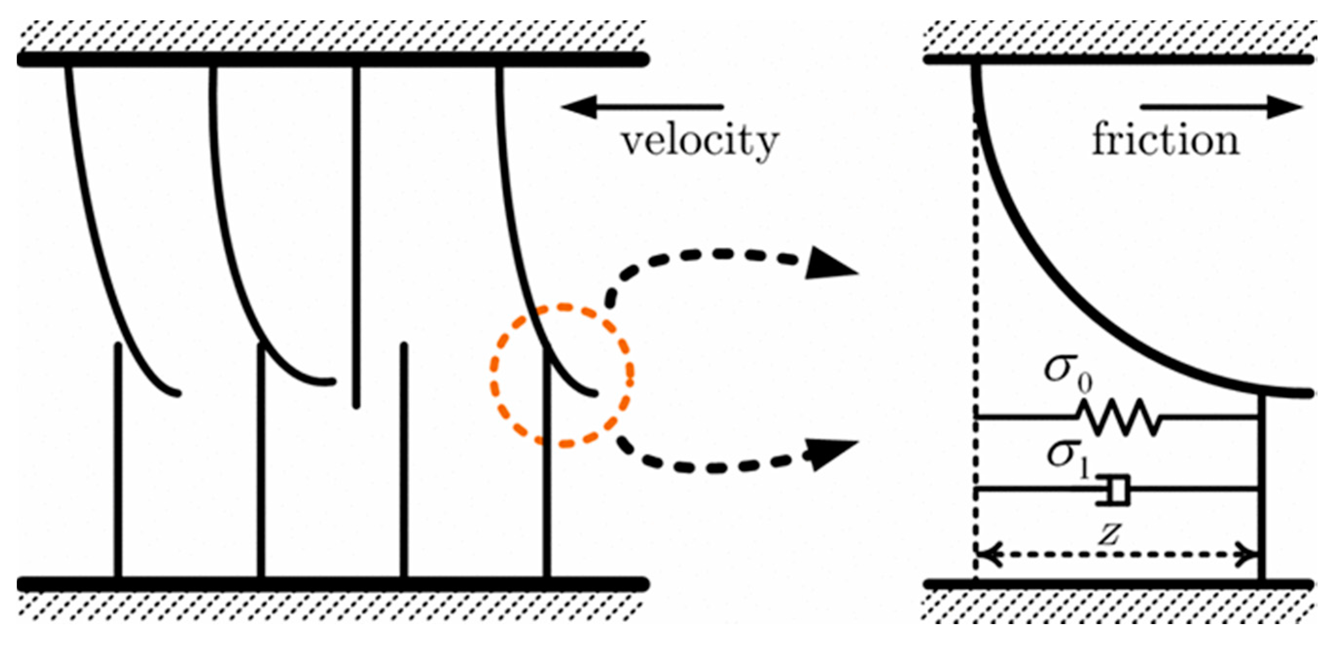
2.2. Friction Force Modeling
2.3. Cutting Force Modeling
2.4. Axial Insertion Force Modeling
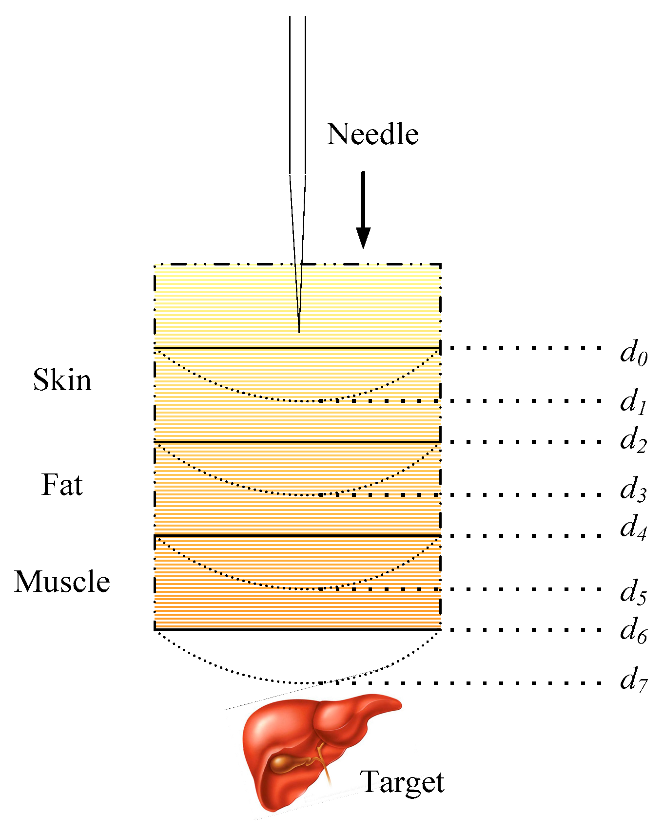
2.5. Multilayer Insertion Force Modeling
3. Needle Insertion Force Measurement
3.1. Direct Needle Insertion Force Measurement
3.2. Indirect Needle Insertion Force Estimation
4. Influence Factor of Needle Insertion Force
4.1. Needle Properties
4.2. Tissue Characteristics
4.3. Robot-Assisted Insertion Method
5. Parameter Identification for Needle Insertion Force Control
5.1. Offline Parameter Identification
5.2. Online Parameter Identification
6. Robot-Assisted Needle Insertion Force Control System
6.1. Robot-Assisted Needle Insertion Force Control System
6.2. Related Force Control Algorithm
7. Discussion
8. Challenges and Future Work
- The establishment of virtual surgery model.
- Delay problem caused by the ultra-long distance.
- The enhancement of human-computer collaboration and the system transparency.
- The abundance of information collection and feedback in the focus area.
- The improvement of the apparatus space movement.
9. Conclusions
Acknowledgments
Conflicts of interest
References
- Abolhassani, N.; Patel, R.; Moallem, M. Needle insertion into soft tissue: A survey. Med. Eng. Phys. 2007, 29, 413–431. [Google Scholar] [CrossRef] [PubMed]
- Misra, S.; Ramesh, K.; Okamura, A. Modeling of tool-tissue interactions for computer-based surgical simulation: A literature review. Presence 2008, 17, 463–491. [Google Scholar] [CrossRef] [PubMed]
- Xiong, L.F.; Chng, C.B.; Chui, C.K.; Yu, P.W.; Li, Y. Shared control of a medical robot with haptic guidance. Int. J. Comput. Assist. Radiol. Surg. 2017, 12, 137–147. [Google Scholar] [CrossRef] [PubMed]
- Cowan, N.J.; Goldberg, K.; Chirikjian, G.S.; Fichtinger, G.; Alterovitz, R.; Reed, K.B.; Kallem, V.; Park, W.; Misra, S.; Okamura, A.M. Robotic needle steering: Design, modeling, planning, and image guidance. In Surgical Robotics; Springer: New York, NY, USA, 2011; pp. 557–582. [Google Scholar]
- Van Gerwen, D.J.; Dankelman, J.; van den Dobbelsteen, J.J. Needle-tissue interaction forces—A survey of experimental data. Med. Eng. Phys. 2012, 34, 665–680. [Google Scholar] [CrossRef] [PubMed]
- Elgezua, I.; Kobayashi, Y.; Fujie, M.G. Survey on current state-of-the-art in needle insertion robots: Open challenges for application in real surgery. Proc. CIrP 2013, 5, 94–99. [Google Scholar] [CrossRef]
- Ruurda, J.P.; van Vroonhoven, T.J.; Broeders, I.A.M.J. Robot-assisted surgical systems: A new era in laparoscopic surgery. Ann. R. Coll. Surg. Eng. 2002, 84, 223. [Google Scholar] [CrossRef]
- Dogangil, G.; Davies, B.L.; Y Baena, F.R. A review of medical robotics for minimally invasive soft tissue surgery. Proc. Inst. Mech. Eng. H J. Eng. Med. 2010, 24, 653–679. [Google Scholar] [CrossRef] [PubMed]
- Ghezzi, T.L.; Corleta, O.C. 30 Years of Robotic Surgery. World J. Surg. 2016, 40, 2550–2557. [Google Scholar] [CrossRef] [PubMed]
- Su, H.; Shang, W.; Li, G.; Patel, N.; Fischer, G.S. An MRI-Guided Telesurgery System Using a Fabry-Perot Interferometry Force Sensor and a Pneumatic Haptic Device. Ann. Biomed. Eng. 2017, 45, 1–12. [Google Scholar] [CrossRef] [PubMed]
- Kronreif, G.; Furst, M.; Kettenbach, J.; Figl, M.; Hanel, R. Robotic guidance for percutaneous interventions. Adv. Robot. 2003, 17, 541–560. [Google Scholar] [CrossRef]
- Hing, J.T.; Brooks, A.D.; Desai, J.P. Reality-based needle insertion simulation for haptic feedback in prostate brachytherapy. In Proceedings of the IEEE International Conference on Robotics and Automation, ICRA, Orlando, FL, USA, 15–19 May 2006; pp. 619–624. [Google Scholar]
- Villani, L.; De Schutter, J. Force control. In Springer Handbook of Robotics; Springer: Berlin/Heidelberg, Germany, 2008; pp. 161–185. [Google Scholar]
- Heng, P.A.; Wong, T.T.; Leung, K.M.; Chui, Y.P.; Sun, H. A haptic needle manipulation simulator for Chinese acupuncture learning and training. Int. J. Image Graph. 2006, 6, 205–230. [Google Scholar] [CrossRef]
- Barbé, L.; Bernard, B.; de Michel, M.; Afshin, G. In vivo model estimation and haptic characterization of needle insertions. Int. J. Robot. Res. 2007, 26, 1283–1301. [Google Scholar] [CrossRef]
- Kokes, R.; Lister, K.; Gullapalli, R.; Zhang, B.; MacMillan, A.; Richard, H.; Desai, J.P. Towards a teleoperated needle driver robot with haptic feedback for RFA of breast tumors under continuous MRI. Med. Image Anal. 2009, 13, 445–455. [Google Scholar] [CrossRef] [PubMed]
- Kim, P.; Kim, S.; Choi, S.H.; Oh, J.S.; Choi, S.B. Force modeling for incision surgery into tissue with haptic application. In SPIE Smart Structures and Materials+ Nondestructive Evaluation and Health Monitoring. International Society for Optics and Photonics; SPIE: Bellingham, WA, USA, 2015; p. 94311N. [Google Scholar]
- Lee, S.R.; Uhm, C.H.; Seong, M.S.; Oh, J.S.; Choi, S.B. Repulsive force control of minimally invasive surgery robot associated with three degrees of freedom electrorheological fluid-based haptic master. Proc. Inst. Mech. Eng. C J. Mech. Eng. Sci. 2013, 228, 1606–1621. [Google Scholar] [CrossRef]
- Kermani, M.R.; Patel, R.V.; Moallem, M. Friction identification and compensation in robotic manipulators. IEEE Trans. Inst. Meas. 2007, 56, 2346–2353. [Google Scholar] [CrossRef]
- Wells, T.S.; MacLachlan, R.; Riviere, C.N. Toward hybrid position/force control for an active handheld micromanipulator. In Proceedings of the IEEE International Conference on Robotics and Automation (ICRA), Hong Kong, China, 31 May–7 June 2014; pp. 772–777. [Google Scholar]
- Zeng, G.; Hemami, A. An overview of robot force control. Robotica 1997, 15, 473–482. [Google Scholar] [CrossRef]
- Okamura, A.M.; Simone, C.; Leary, M. Force modeling for needle insertion into soft tissue. IEEE Trans. Biomed. Eng. 2004, 51, 1707–1716. [Google Scholar] [CrossRef] [PubMed]
- Simone, C. Modeling of Needle Insertion Forces for Percutaneous Therapies. Master’s Thesis, Johns Hopkins University, Baltimore, MD, USA, 2002. [Google Scholar]
- D’Aulignac, D.; Balaniuk, R.; Laugier, C. A haptic interfacefor a virtual exam of the human thigh. In Proceedings of the IEEE International Conference on ICRA’00 Robotics and Automation, San Francisco, CA, USA, 24–28 April 2000; Volume 3, pp. 2452–2457. [Google Scholar]
- Jiang, S.; Li, P.; Yu, Y.; Liu, J.; Yang, Z. Experimental study of needle-tissue interaction forces: Effect of needle geometries, insertion methods and tissue characteristics. J. Biomech. 2014, 47, 3344–3353. [Google Scholar] [CrossRef] [PubMed]
- Sneddon, I.N. The relation between load and penetration in the axisymmetric boussinesq problem for a punch of arbitrary profile. Int. J. Eng. Sci. 1965, 3, 47–57. [Google Scholar] [CrossRef]
- Podder, T.K.; Sherman, J.; Messing, E.M.; Rubens, D.J.; Fuller, D.; Strang, J.G.; Brasacchio, R.A.; Yu, Y. Needle insertion force estimation model using procedure-specific and patient-specific criteria. In Proceedings of the 28th Annual International Conference on Engineering in Medicine and Biology Society, New York, NY, USA, 30 Augest–3 September 2006; pp. 555–558. [Google Scholar]
- Maurin, B.; Barbe, L.; Bayle, B.; Zanne, P.; Gangloff, J.; De Mathelin, M.; Gangi, A.; Soler, L.; Forgione, A. In vivo study of forces during needle insertions. In Proceedings of the Medical Robotics, Navigation and Visualisation Scientific workshop, Remagen, Germany, 11–12 March 2004; pp. 1–8. [Google Scholar]
- Dimaio, S.P.; Salcudean, S.E. Needle insertion modeling and simulation. IEEE Trans. Robot. Autom. 2003, 19, 864–875. [Google Scholar] [CrossRef]
- Yankelevsky, D.Z.; Eisenberger, M.; Adin, M.A. Analysis of beams on nonlinear Winkler foundation. Comput. Struct. 1989, 31, 287–292. [Google Scholar] [CrossRef]
- Yang, T.; Yin, H.; Zhao, X.; Han, J.; Xu, W. Interaction modeling and simulation of a flexible needle insertion into soft tissues. In Proceedings of the 41st International Symposium on Robotics, ISR/Robotik, Munich, Germany, 2–3 June 2014; pp. 1–6. [Google Scholar]
- Yan, H.; Liu, P.X.; Zhang, J. Modelling of needle insertion forces for surgical simulation. In Proceedings of the IEEE International Conference on Mechatronics and Automation, Niagara Falls, ON, Canada, 29 July–1 Augest 2005; Volume 2, pp. 592–595. [Google Scholar]
- Dupont, P.E.; Armstrong, B.; Hayward, V. Elasto-plastic friction model: Contact compliance and stiction. In Proceedings of the American Control Conference, Chicago, IL, USA, 28–30 June 2000; Volume 2, pp. 1072–1077. [Google Scholar]
- Kobayashi, Y.; Sato, T.; Fujie, M.G. Modeling of friction force based on relative velocity between liver tissue and needle for needle insertion simulation. In Proceedings of the Annual International Conference on IEEE Engineering in Medicine and Biology Society (EMBC), Minneapolis, MN, USA, 3–6 September 2009; pp. 5274–5278. [Google Scholar]
- Carra, A.; Avila-Vilchis, J.C. Needle insertion modeling through several tissue layers. In Proceedings of the Automation and Robotics (CAR), 2nd International Asia Conference on Informatics in Control, Wuhan, China, 6–7 March 2010; Volume 1, pp. 237–240. [Google Scholar]
- Carra, A.; Avila-Vilchis, J.C. Multilayer needle insertion modeling for robotic percutaneous therapy. In Proceedings of the 4th International Conference on Bioinformatics and Biomedical Engineering (iCBBE), Chengdu, China, 18–20 June 2010; pp. 1–4. [Google Scholar]
- Barbé, L.; Bayle, B.; de Mathelin, M.; Gangi, A. Needle insertions modelling: Identifiability and limitations. Modell. Control. Biomed. Syst. 2006, 2006, 129. [Google Scholar] [CrossRef]
- He, X.; Chen, Y.; Tang, L. Modeling of flexible needle for haptic insertion simulation. In Proceedings of the IEEE Conference on Virtual Environments, Human-Computer Interfaces and Measurement Systems, VECIMS 2008, Istanbul, Turkey, 14–16 July 2008; pp. 184–189. [Google Scholar]
- Mahvash, M.; Hayward, V. Haptic rendering of cutting: A fracture mechanics approach. Haptics-e 2001, 2, 1–12. [Google Scholar]
- Crouch, J.R.; Schneider, C.M.; Wainer, J.; Okamura, A.M. A velocity-dependent model for needle insertion in soft tissue. In Medical Image Computing and Computer-Assisted Intervention-Miccai; Springer: Berlin/Heidelberg, Germany, 2005; pp. 624–632. [Google Scholar]
- Asadian, A.; Kermani, M.R.; Patel, R.V. A compact dynamic force model for needle-tissue interaction. In Proceedings of the Annual International Conference on IEEE Engineering in Medicine and Biology Society (EMBC), Buenos Aires, Argentina, 31 August–4 September 2010; pp. 2292–2295. [Google Scholar]
- Asadian, A.; Patel, R.V.; Kermani, M.R. A distributed model for needle-tissue friction in percutaneous interventions. In Proceedings of the IEEE International Conference on Robotics and Automation (ICRA), Shanghai, China, 9–13 May 2011; pp. 1896–1901. [Google Scholar]
- Asadian, A. Robotics-Assisted Needle Steering for Percutaneous Interventions: Modeling and Experiments. 2013. Available online: https://ir.lib.uwo.ca/etd/1260/ (accessed on 3 May 2013).
- Wang, L.; Hirai, S. A local constraint method for needle insertion modeling and simulation. In Proceedings of the IEEE International Workshop on Haptic Audio Visual Environments and Games (HAVE), Hebei, China, 14–17 October 2011; pp. 39–44. [Google Scholar]
- Asadian, A.; Kermani, M.R.; Patel, R.V. A novel force modeling scheme for needle insertion using multiple Kalman filters. IEEE Trans. Instrum. Meas. 2012, 61, 429–438. [Google Scholar] [CrossRef]
- Yan, K.; Podder, T.; Li, L.; Joseph, J.; Rubens, D.R.; Messing, E.M.; Liao, L.; Yu, Y. A real-time prostate cancer detection technique using needle insertion force and patient-specific criteria during percutaneous intervention. Med. Phys. 2009, 36, 4184–4190. [Google Scholar] [CrossRef] [PubMed]
- Asadian, A.; Kermani, M.R.; Patel, R.V. An analytical model for deflection of flexible needles during needle insertion. In Proceedings of the IEEE/RSJ International Conference on Intelligent Robots and Systems (IROS), San Francisco, CA, USA, 25–30 September 2011; pp. 2551–2556. [Google Scholar]
- Gordon, A.; Kim, I.; Barnett, A.C.; Moore, J.Z. Needle Insertion Force Model for Haptic Simulation. In Proceedings of the ASME 10th International Manufacturing Science and Engineering Conference, Charlotte, CA, USA, 8–12 June 2015. [Google Scholar]
- Haddadi, A.; Hashtrudi-Zaad, K. Development of a dynamic model for bevel-tip flexible needle insertion into soft tissues. In Proceedings of the Annual International Conference on IEEE Engineering in Medicine and Biology Society (EMBC), Boston, MA, USA, 30 August–3 September 2011; pp. 7478–7482. [Google Scholar]
- Elgezua, I.; Kobayashi, Y.; Fujie, M.G. Estimation of needle tissue interaction based on non-linear elastic modulus and friction force patterns. In Proceedings of the IEEE/RSJ International Conference on Intelligent Robots and Systems (IROS 2014), Chicago, IL, USA, 14–18 September 2014; pp. 4315–4322. [Google Scholar]
- Wang, L.; Wang, Z.; Hirai, S. Modeling and simulation of friction forces during needle insertion using local constraint method. In Proceedings of the IEEE/RSJ International Conference on Intelligent Robots and Systems (IROS), Vilamoura, Portugal, 7–12 October 2012; pp. 4926–4932. [Google Scholar]
- Maurel, W. 3D Modeling of the Human Upper Limb Including the Biomechanics of Joints, Muscles and Soft Tissues. Ph.D. Thesis, Laboratoire d’Infographie-Ecole Polytechnique Federale deLausanne, Lausanne, Switzerland, 1999. [Google Scholar]
- Richard, C.; Cutkosky, M.R.; MacLean, K. Friction identification for haptic display. In Proceedings of the ASME IMECE, Mechanical Engineers, Dynamic Systems and Control Division, Nashville, TN, USA, 14–19 November 1999; Volume 67, pp. 327–334. [Google Scholar]
- Simone, C.; Okamura, A.M. Modeling of needle insertion forces for robot-assisted percutaneous therapy. In Proceedings of the IEEE International Conference on Robotics and Automation, ICRA’02, Washington, DC, USA, 11–15 May 2002; Volume 2, pp. 2085–2091. [Google Scholar]
- Asadian, A.; Patel, R.V.; Kermani, M.R. Dynamics of translational friction in needle-tissue interaction during needle insertion. Ann. Biomed. Eng. 2014, 42, 73–85. [Google Scholar] [CrossRef] [PubMed]
- Stellman, J.T. Development, Production, and Characterization of Plastic Hypodermic Needles. Master Thesis, Georgia Institute of Technology, Atlanta, GA, USA, 2009. [Google Scholar]
- Fung, Y.C. Biomechanics—Mechanical Properties of Living Tissues, 2nd ed.; Springer: New York, NY, USA, 1993. [Google Scholar]
- Mesquita, A.D.; Coda, H.B. A simple Kelvin and Boltzmann viscoelastic analysis of three-dimensional solids by the boundary element method. Eng. Anal. Bound. Elem. 2003, 27, 885–895. [Google Scholar] [CrossRef]
- Chentanez, N.; Alterovitz, R.; Ritchie, D.; Cho, L.; Hauser, K.K.; Goldberg, K.; Shewchuk, J.R.; O’Brien, J.F. Interactive Simulation of Surgical Needle Insertion and Steering. ACM 2009, 28, 88. [Google Scholar]
- Fukushima, Y.; Kiyoshi, N. Estimation of the friction force during the needle insertion using the disturbance observer and the recursive least square. Robomech. J. 2014, 1, 1–8. [Google Scholar] [CrossRef]
- Kataoka, H.; Washio, T.; Chinzei, K.; Mizuhara, K.; Simone, C.; Okamura, A.M. Measurement of the tip and friction force acting on a needle during penetration. In Medical Image Computing and Computer-Assisted Intervention—MICCAI 2002; Springer: Berlin/Heidelberg, Germany, 2002; pp. 216–223. [Google Scholar]
- Matsumiya, K.; Momoi, Y.; Kobayashi, E.; Sugano, N.; Yonenobu, K.; Inada, H.; Tsuji, T.; Sakuma, I. Analysis of forces during robotic needle insertion to human vertebra. In Medical Image Computing and Computer-Assisted Intervention-MICCAI; Springer: Berlin/Heidelberg, Germany, 2003; pp. 271–278. [Google Scholar]
- Mo, Z.; Xu, W.; Broderick, N. A Fabry-Perot optical fiber force sensor based on intensity modulation for needle tip force sensing. In Proceedings of the 2015 6th International Conference on Automation, Robotics and Applications (ICARA), Queenstown, New Zealand, 17–19 February 2015; pp. 376–380. [Google Scholar]
- Xu, J. High Temperature High Bandwidth Fiber Optic Pressure Sensors. PhD Thesis, Virginia Polytechnic Institute and State University, Blacksburg, VA, USA, 2005. [Google Scholar]
- Piccin, O.; Barbé, L.; Bayle, B.; De Mathelin, M.; Gangi, A. A force feedback teleoperated needle insertion device for percutaneous procedures. Int. J. Robot. Res. 2009, 28, 1154–1168. [Google Scholar] [CrossRef]
- Samur, E.; Sedef, M.; Basdogan, C.; Avtan, L.; Duzgun, O. A robotic indenter for minimally invasive measurement and characterization of soft tissue response. Med. Image Anal. 2007, 11, 361–373. [Google Scholar] [CrossRef] [PubMed]
- Khalaji, I.; Hadavand, M.; Asadian, A.; Patel, R.V.; Naish, M.D. Analysis of needle-tissue friction during vibration-assisted needle insertion. In Proceedings of the IEEE/RSJ International Conference on Intelligent Robots and Systems (IROS), Tokyo, Japan, 3–7 November 2013; pp. 4099–4104. [Google Scholar]
- Moore, J.Z.; Albert, J.S.; McLaughlin, P.W.; McGill, C.S.; Zhang, Q.H.; Zheng, H.J. Blade oblique cutting of tissue for investigation of biopsy needle insertion. Trans. NAMRI/SME 2009, 37, 49–56. [Google Scholar]
- Wedlick, T.R.; Allison, M.O. Characterization of robotic needle insertion and rotation in artificial and ex vivo tissues. In Proceedings of the 4th IEEE RAS & EMBS International Conference on Biomedical Robotics and Biomechatronics (BioRob), Rome, Italy, 24–27 June 2012; pp. 62–68. [Google Scholar]
- De Lorenzo, D.; Yoshihiko, K.; De Elena, M.; Kiyoyuki, C.; Allison, M.O. Coaxial needle insertion assistant with enhanced force feedback. IEEE Trans. Biomed. Eng. 2013, 60, 379–389. [Google Scholar] [CrossRef] [PubMed]
- Kobayashi, Y.; Onishi, A.; Watanabe, H.; Hoshi, T.; Kawamura, K.; Hashizume, M.; Fujie, M.G. Development of an integrated needle insertion system with image guidance and deformation simulation. Comput. Med. Image Graph. 2010, 34, 9–18. [Google Scholar] [CrossRef] [PubMed]
- Boroomand, A.; Tavakoli, M.; Sloboda, R.; Usmani, N. Dynamical modeling and controllability analysis of a flexible needle in soft tissue. Int. J. Model. Simul. Sci. Comput. 2014, 5, 1350031. [Google Scholar] [CrossRef]
- Fukushima, Y.; Saito, K.; Naemura, K. Estimation of the cutting force using the dynamic friction coefficient obtained by reaction force during the needle insertion. Proc. CIRP 2013, 5, 265–269. [Google Scholar] [CrossRef]
- Casanova, F.; Paul, R.C.; Malisa, S. In vivo evaluation of needle force and friction stress during insertion at varying insertion speed into the brain. J. Neurosci. Methods 2014, 237, 79–89. [Google Scholar] [CrossRef] [PubMed]
- Van Veen, Y.R.; Jahya, A.; Misra, S. Macroscopic and microscopic observations of needle insertion into gels. Proc. Inst. Mech. Eng. H J. Eng. Med. 2012, 226, 441–449. [Google Scholar] [CrossRef] [PubMed]
- Mahvash, M.; Dupont, P.E. Mechanics of dynamic needle insertion into a biological material. IEEE Trans. Biomed. Eng. 2010, 57, 934–943. [Google Scholar] [CrossRef] [PubMed]
- Washio, T.; Chinzei, K. Needle force sensor, robust and sensitive detection of the instant of needle puncture. In Medical Image Computing and Computer-Assisted Intervention–MICCAI; Springer: Berlin/Heidelberg, Germany, 2004; pp. 113–120. [Google Scholar]
- Wang, Y.; Chen, R.K.; Tai, B.L.; McLaughlin, P.W.; Shih, A.J. Optimal needle design for minimal insertion force and bevel length. Med. Eng. Phys. 2014, 36, 1093–1100. [Google Scholar] [CrossRef] [PubMed]
- Gao, L.Y.; Zhang, Q.H.; Liu, M. Orthogonal cutting of biological soft tissue with single cutting edge. In Applied Mechanics and Materials; Scientific.Net: Zurich, Switzerland, 2012; Volume 121, pp. 283–287. [Google Scholar]
- Dehghan, E.; Wen, X.; Zahiri-Azar, R.; Marchal, M.; Salcudean, S.E. Parameter identification for a needle-tissue interaction model. In Proceedings of the 29th Annual International Conference on IEEE Engineering in Medicine and Biology Society, EMBS 2007, Lyon, France, 22–26 August 2007; pp. 190–193. [Google Scholar]
- Buzurovic, I.; Podder, T.K.; Yu, Y. Prediction control for brachytherapy robotic system. J. Robot. 2010, 2010, 581840. [Google Scholar] [CrossRef]
- Leary, M.; Simone, C.; Washio, T.; Yoshinaka, K.; Okamura, A.M. Robotic needle insertion: Effects of friction and needle geometry. In Proceedings of the ICRA’03, IEEE International Conference on Robotics and Automation, Taiwan, Taiwan, 14–19 September 2003; Volume 2, pp. 1774–1780. [Google Scholar]
- Hing, J.T.; Brooks, A.D.; Desai, J.P. A biplanar fluoroscopic approach for the measurement, modeling, and simulation of needle and soft-tissue interaction. Med. Image Anal. 2007, 11, 62–78. [Google Scholar] [CrossRef] [PubMed]
- Kataoka, H.; Washio, T.; Audette, M.; Mizuhara, K. A model for relations between needle deflection, force, and thickness on needle penetration. In Medical Image Computing and Computer-Assisted Intervention–MICCAI 2001; Springer: Berlin/Heidelberg, Germany, 2001; pp. 966–974. [Google Scholar]
- Gao, L.; Zhang, Q.; Liu, M. Indentation test of soft tissue for investigating needle tissue machining. In Proceedings of the Second International Conference on Mechanic Automation and Control Engineering (MACE), Hohhot, China, 15–17 July 2011; pp. 348–351. [Google Scholar]
- Alja’afreh, T. Investigating the needle dynamic response during insertion into soft tissue. Proc. Inst. Mech. Eng. H. J. Eng. Med. 2010, 224, 531–540. [Google Scholar] [CrossRef] [PubMed]
- Schwartz, J.M.; Denninger, M.; Rancourt, D.; Moisan, C.; Laurendeau, D. Modelling liver tissue properties using a non-linear visco-elastic model for surgery simulation. Med. Image Anal. 2005, 9, 103–112. [Google Scholar] [CrossRef] [PubMed]
- Roxhed, N.; Gasser, T.C.; Griss, P.; Holzapfel, G.; Stemme, G. Penetration-enhanced ultrasharp microneedles and prediction on skin interaction for efficient transdermal drug delivery. J. Microelectromech. Syst. 2007, 16, 1429–1440. [Google Scholar] [CrossRef]
- Passerotti, C.C.; Begg, N.; Penna, F.J.; Passerotti, A.M.A.; Leite, K.R.; Antunes, A.A.; Srougi, M.; Retik, A.B.; Nguyen, H.T. Safety profile of trocar and insufflation needle access systems in laparoscopic surgery. J. Am. Coll. Surg. 2009, 209, 222–232. [Google Scholar] [CrossRef] [PubMed]
- Bi, D.; Lin, Y. Vibrating needle insertion for trajectory optimization. In Proceedings of the 7th World Congress on Intelligent Control and Automation, WCICA 2008, Chongqing, China, 25–27 June 2008; pp. 7444–7448. [Google Scholar]
- Chanthasopeephan, T.; Desai, J.P.; Lau, A.C. Study of soft tissue cutting forces and cutting speeds. Studies Health Technol. Inform. 2004, 56–62. [Google Scholar]
- Han, P.; Ehmann, K. Study of the effect of cannula rotation on tissue cutting for needle biopsy. Med. Eng. Phys. 2013, 35, 1584–1590. [Google Scholar] [CrossRef] [PubMed]
- Su, H.; Fischer, G.S. A 3-axis optical force/torque sensor for prostate needle placement in magnetic resonance imaging environments. In Proceedings of the IEEE International Conference on Technologies for Practical Robot Applications, TePRA 2009, Woburn, MA, USA, 9–10 November 2009; pp. 5–9. [Google Scholar]
- Peirs, J.; Clijnen, J.; Reynaerts, D.; Van Brussel, H.; Herijgers, P.; Corteville, B.; Boone, S. A micro optical force sensor for force feedback during minimally invasive robotic surgery. Sens. Act. A Phys. 2004, 115, 447–455. [Google Scholar] [CrossRef]
- Zhai, J.; Karuppasamy, K.; Zvavanjanja, R.; Fisher, M.; Fisher, A.C.; Gould, D.; How, T. A sensor for needle puncture force measurement during interventional radiological procedures. Med. Eng. Phys. 2013, 35, 350–356. [Google Scholar] [CrossRef] [PubMed]
- Gijbels, A.; Vander Poorten, E.B.; Stalmans, P.; Reynaerts, D. Development and experimental validation of a force sensing needle for robotically assisted retinal vein cannulations. In Proceedings of the IEEE International Conference on Robotics and Automation (ICRA), Seattle, WA, USA, 26–30 May 2015; pp. 2270–2276. [Google Scholar]
- Gonenc, B.; Taylor, R.H.; Iordachita, I.; Gehlbach, P.; Handa, J. Force-sensing microneedle for assisted retinal vein cannulation. In Proceedings of the 2014 IEEE on SENSORS, Valencia, Spain, 2–5 November 2014; pp. 698–701. [Google Scholar]
- Elayaperumal, S.; Bae, J.H.; Christensen, D.; Cutkosky, M.R.; Daniel, B.L.; Black, R.J.; Costa, J.M.; Faridian, F.; Moslehi, B. MR-compatible biopsy needle with enhanced tip force sensing. In Proceedings of the World Haptics Conference (WHC), Daejeon, Korea, 14–17 April 2013; pp. 109–114. [Google Scholar]
- Gossot, D.; Validire, P.; Matsumoto, S.; Tokumura, H.; Shimomura, K.; Flowers, J.; Borenstein, N.; Daniel, P. Development of an ultrasonically activated trocar system. Surg. Endosc. Int. Tech. 2002, 16, 210–214. [Google Scholar] [CrossRef] [PubMed]
- Puangmali, P.; Althoefer, K.; Seneviratne, L.D.; Murphy, D.; Dasgupta, P. State-of-the-art in force and tactile sensing for minimally invasive surgery. Sens. J. IEEE 2008, 8, 371–381. [Google Scholar] [CrossRef]
- Motamed, M.; Yan, J. A review of biological, biomimetic and miniature force sensing for microflight. In Proceedings of the IEEE/RSJ International Conference on Intelligent Robots and Systems, Edmonton, AL, Canada, 2–6 August 2005; pp. 3939–3946. [Google Scholar]
- Franco, E.; Ristic, M. Adaptive control of a master-slave system for teleoperated needle insertion under MRI-guidance. In Proceedings of the 23th Mediterranean Conference on Control and Automation (MED), Torremolinos, Spain, 16–19 June 2015; pp. 61–67. [Google Scholar]
- Abushagur, A.A.; Arsad, N.; Reaz, M.I.; Bakar, A. Advances in bio-tactile sensors for minimally invasive surgery using the Fibre Bragg grating force sensor technique: A survey. Sensors 2014, 14, 6633–6665. [Google Scholar] [CrossRef] [PubMed]
- Hashtrudi-Zaad, K.; Salcudean, S. Transparency in time-delayed systems and the effect of local force feedback for transparent teleoperation. IEEE Trans. Robot. Autom. 2002, 18, 108–114. [Google Scholar] [CrossRef]
- Dario, P.; Bergamasco, M. An advanced robot system for automated diagnostic tasks through palpation. IEEE Trans. Biomed. Eng. 1988, 35, 118–126. [Google Scholar] [CrossRef] [PubMed]
- Kontarinis, D.A.; Son, J.S.; Peine, W.J.; Howe, R.D. A tactile shape sensing and display system for teleoperated manipulation. In Proceedings of the IEEE International Conference on Robotics and automation, Nagoya, Japan, 21–27 May 1995; pp. 641–646. [Google Scholar]
- Chee, C.Y.K.; Tong, L.; Steven, G.P. A review on the modelling of piezoelectric sensors and actuators incorporated in intelligent structures. J. Intell. Mater. Syst. Struct. 1998, 9, 3–19. [Google Scholar] [CrossRef]
- Katsura, S.; Matsumoto, Y.; Ohnishi, K. Modeling of force sensing and validation of disturbance observer for force control. IEEE Trans. Ind. Electron. 2007, 54, 530–538. [Google Scholar] [CrossRef]
- Eom, K.S.; Suh, I.H.; Chung, W.K.; Oh, S.-R. Disturbance observer based force control of robot manipulator without force sensor. In Proceedings of the IEEE International Conference on Robotics and Automation, Leuven, Belgium, 20 May 1998; pp. 3012–3017. [Google Scholar]
- Tadano, K.; Kawashima, K. Development of 4-dofs forceps with force sensing using pneumatic servo system. In Proceedings of the 2006 IEEE International Conference on Robotics and Automation, Orlando, FL, USA, 15–19 May 2006; pp. 2250–2255. [Google Scholar]
- Tavakoli, M.; Patel, R.V.; Moallem, M. Bilateral control of a teleoperator for soft tissue palpation: Design and experiments. In Proceedings of the IEEE International Conference on Robotics and Automation, Orlando, FL, USA, 15–19 May 2006; pp. 3280–3285. [Google Scholar]
- Podder, T.K.; Sherman, J.; Clark, D.P.; Messing, E.M.; Rubens, D.J.; Strang, J.G.; Liao, L.; Brasacchio, R.A.; Zhang, Y.; Ng, W.S.; et al. Evaluation of robotic needle insertion in conjunction with in vivo manual insertion in the operating room. In Proceedings of the IEEE International Workshop on Robot and Human Interactive Communication, ROMAN 2005, Nashville, TN, USA, 13–15 August 2005; pp. 66–72. [Google Scholar]
- Majewicz, A.; Marra, S.P.; Van Vledder, M.; Lin, M.; Choti, M.A.; Song, D.Y.; Okamura, A.M. Robotic Behavior of tip-steerable needles in ex vivo and in vivo tissue. IEEE Trans. Biomed. Eng. 2012, 59, 2705–2715. [Google Scholar] [CrossRef] [PubMed]
- Li, P.; Jiang, S.; Yu, Y.; Yang, J.; Yang, Z. Biomaterial characteristics and application of silicone rubber and PVA hydrogels mimicked in organ groups for prostate brachytherapy. J. Mech. Behav. Biomed. 2015, 49, 220–234. [Google Scholar] [CrossRef] [PubMed]
- Suzuki, T.; Tanaka, A.; Fukuyama, H.; Nishiyama, J.; Kanazawa, M.; Oda, M.; Takahashi, M. Differences in penetration force of intravenous catheters: Effect of grinding methods on inner needles of intravenous catheters. Tokai J. Exp. Clin. Med. 2004, 29, 175–181. [Google Scholar] [PubMed]
- Podder, T.K.; Clark, D.P.; Fuller, D.; Sherman, J.; Ng, W.S.; Liao, L.; Rubens, D.J.; Strang, J.G.; Messing, E.M.; Zhang, Y.D.; et al. Effects of velocity modulation during surgical needle insertion. In Proceedings of the 27th Annual International Conference on Engineering in Medicine and Biology Society, IEEE-EMBS 2005, Shanghai, China, 17–18 January 2006; pp. 5766–5770. [Google Scholar]
- Gokgol, C.; Basdogan, C.; Canadinc, D. Estimation of fracture toughness of liver tissue: Experiments and validation. Med. Eng. Phys. 2012, 34, 882–891. [Google Scholar] [CrossRef] [PubMed]
- Abolhassani, N.; Rajni, P.; Mehrdad, M. Experimental study of robotic needle insertion in soft tissue. Int. Con. Ser. 2004, 1268, 797–802. [Google Scholar] [CrossRef]
- Mahvash, M.; Dupont, P.E. Fast needle insertion to minimize tissue deformation and damage. In Proceedings of the IEEE International Conference on Robotics and Automation, ICRA’09, Kobe, Japan, 12–17 May 2009; pp. 3097–3102. [Google Scholar]
- Moore, J.Z.; Kostyantyn, M.; Albert, J.S.; Kornel, F.E. Hollow needle tissue insertion force model. CIRP Ann.-Manuf. Technol. 2011, 60, 57–60. [Google Scholar] [CrossRef]
- Hirsch, L.; Michael, G.; Julie, B.; John, M. Impact of a modified needle tip geometry on penetration force as well as acceptability, preference, and perceived pain in subjects with diabetes. J. Diabetes Sci. Technol. 2012, 6, 328–335. [Google Scholar] [CrossRef] [PubMed]
- Misra, S.; Reed, K.B.; Douglas, A.S.; Ramesh, K.T.; Okamura, A.M. Needle-tissue interaction forces for bevel-tip steerable needles. In Proceedings of the 2nd IEEE RAS & EMBS International Conference on Biomedical Robotics and Biomechatronics, BioRob 2008, Scottsdale, AZ, USA, 19–22 October 2008; pp. 224–231. [Google Scholar]
- Tan, L.; Qin, X.M.; Zhang, H.C.; Xin, Q.; Zhang, Q.H. Penetration force in biopsy under condition of biomimetic vibration. Appl. Mech. Mater. 2015, 709, 436–440. [Google Scholar] [CrossRef]
- Abolhassani, N.; Patel, R.; Moallem, M. Trajectory generation for robotic needle insertion in soft tissue. In Proceedings of the 26th Annual International Conference on IEEE Engineering in Medicine and Biology Society, IEMBS’04 2004, San Francisco, CA, USA, 1–5 September 2004; Volume 1, pp. 2730–2733. [Google Scholar]
- Kong, X.Q.; Wu, C.W. Measurement and prediction of insertion force for the mosquito fascicle penetrating into human skin. J. Bionic Eng. 2009, 6, 143–152. [Google Scholar] [CrossRef]
- Westbrook, J.L.; Uncles, D.R.; Sitzman, B.T.; Carrie, L.E. Comparison of the force required for dural puncture with different spinal needles and subsequent leakage of cerebrospinal fluid. Anesth. Anal. 1994, 79, 769–772. [Google Scholar] [CrossRef]
- Westwood, J.D. Force models for needle insertion created from measured needle puncture data. Med. Meets Vir. Real. 2001, 81, 180. [Google Scholar]
- Okuno, D.; Togawa, T.; Saito, H.; Tsuchiya, K. Development of an automatic blood sampling system: Control of the puncturing needle by measuring forces. In Proceedings of the 20th Annual International Conference on IEEE Engineering in Medicine and Biology Society, Hong Kong, China, 1 November 1998; Volume 4, pp. 1811–1812. [Google Scholar]
- Kobayashi, Y.; Onishi, A.; Hoshi, T.; Kawamura, K.; Hashizume, M.; Fujie, M.G. Development and validation of a viscoelastic and nonlinear liver model for needle insertion. Int. J. Comput. Assist. Radiol. Surg. 2009, 4, 53–63. [Google Scholar] [CrossRef] [PubMed]
- Choy, Y.B.; Cao, H.; Tungjitkusolmun, S.; Tsai, J.Z.; Haemmerich, D.; Vorperian, V.R.; Webster, J.G. Mechanical compliance of the endocardium. J. Biomech. 2002, 35, 1671–1676. [Google Scholar] [CrossRef]
- Han, Y.J.; Yi, S.Y.; Lee, Y.J.; Kim, K.H.; Kim, E.J.; Lee, S.D. Quantification of the parameters of twisting-rotating acupuncture manipulation using a needle force measurement system. Int. Med. Res. 2015, 5, 57–65. [Google Scholar] [CrossRef] [PubMed]
- Kobayashi, Y.; Hamano, R.; Watanabe, H.; Hong, J.; Toyoda, K.; Hashizume, M. Use of puncture force measurement to investigate the conditions of blood vessel needle insertion. Med. Eng. Phys. 2013, 35, 684–689. [Google Scholar] [CrossRef] [PubMed]
- Meltsner, M.; Ferrier, N.; Thomadsen, B. Observations on rotating needle insertions using a brachytherapy robot. Phys. Med. Biol. 2007, 52, 6027–6037. [Google Scholar] [CrossRef] [PubMed]
- Naemura, K.; Uchino, Y.; Saito, H. Effect of the needle tip height on the puncture force in a simplified epidural anesthesia simulator. In Proceedings of the 29th Annual International Conference on IEEE EMBS, Lyon, France, 22–26 August 2007; pp. 3504–3507. [Google Scholar]
- Naemura, K.; Sakai, A.; Hayashi, T.; Saito, H. Epidural insertion simulator of higher insertion resistance and drop rate after puncture. In Proceedings of the 30th Annual International Conference on IEEE EMBS, Vancouver, BC, Canada, 20–25 August 2008; pp. 3249–3252. [Google Scholar]
- Reed, K.B.; Okamura, A.M.; Cowan, N.J. Controlling a robotically steered needle in the presence of torsional friction. In Proceedings of the IEEE International Conference on Robotics and Automation, ICRA 2009, Kobe, Japan, 12–17 May 2009; pp. 3476–3481. [Google Scholar]
- Shergold, O.A.; Fleck, N.A. Experimental investigation into the deep penetration of soft solids by sharp and blunt punches, with application to the piercing of skin. J. Biomech. Eng. 2005, 127, 838–848. [Google Scholar] [CrossRef] [PubMed]
- Azar, T.; Hayward, V. Estimation of the Fracture Toughness of Soft Tissue from Needle Insertion; Bello, F., Edwards, E., Eds.; Lecture Notes in Computer Science; Springe: Berlin, Germany, 2008; Volume 5104, pp. 166–175. [Google Scholar]
- Lewis, M.C.; Lafferty, J.P.; Sacks, M.S.; Pallares, V.S.; TerRiet, M. How much work is required to puncture dura with tuohy needles? Brit. J. Anaesth. 2000, 85, 238–241. [Google Scholar] [CrossRef] [PubMed]
- Jung, J.; Lee, J.; Huh, K. Robust contact force estimation for robot manipulators in three-dimensional space. Proc. Inst. Mech. Eng. C J. Mech. Eng. Sci. 2006, 220, 1317–1327. [Google Scholar] [CrossRef]
- Hirose, S.; Yoneda, K. Development of optical six-axial force sensor and its signal calibration considering nonlinear interference. In Proceedings of the IEEE International Conference on Robotics and Automation, Cincinnati, OH, USA, 13–18 May 1990; pp. 46–53. [Google Scholar]
- Xie, Y.; Sun, D.; Liu, C.; Tse, H.Y.; Cheng, S.H. A force control approach to a robot-assisted cell microinjection system. Int. J. Robot. Res. 2010, 29, 1222–1232. [Google Scholar] [CrossRef]
- Keesman, K.J. System Identification: An Introduction; Springer Science & Business Media: London, England, 2011. [Google Scholar]
- Gu, G. Discrete-Time Linear Systems: Theory and Design with Applications; Springer Science & Business Media: New York, NY, USA, 2012. [Google Scholar]
- Monje, C.A.; Chen, Y.; Vinagre, B.M.; Xue, D.; Feliu-Batlle, V. Fractional-Order Systems and Controls: Fundamentals and Applications; Springer Science & Business Media: London, UK, 2010. [Google Scholar]
- Heij, C.; Ran, A.C.; van Schagen, F. Introduction to Mathematical Systems Theory: Linear Systems, Identification and Control; Birkhäuser Verlag: Basel, Switzerland, 2007. [Google Scholar]
- Kostenko, A. Introductory Time Series with R; Springer: New York, NY, USA, 2012; ISBN 978-0-387-88697-8. [Google Scholar]
- Pillonetto, G.; Dinuzzo, F.; Chen, T.; De Nicolao, G.; Ljung, L. Kernel methods in system identification, machine learning and function estimation: A survey. Automatica 2014, 50, 657–682. [Google Scholar] [CrossRef]
- Åström, K.J.; Eykhoff, P. System identification—A survey. Automatica 1971, 7, 123–162. [Google Scholar]
- Ljung, L. System Identification; Birkhäuser: Boston, MA, USA, 1998; pp. 163–173. [Google Scholar]
- Huang, H.B.; Sun, D.; Mills, J.K.; Cheng, S.H. Robotic cell injection system with position and force control: Toward automatic batch biomanipulation. IEEE Trans. Robot. 2009, 25, 727–737. [Google Scholar] [CrossRef]
- Graña, A.; Sánchez, A.; Zemiti, N.; Poignet, P. Modelling and control of an ERF-Based needle insertion training platform. In Information Processing in Computer-Assisted Interventions; Springer: Fukuoka, Japan, 2014; pp. 31–40. [Google Scholar]
- Jayender, J.; Patel, R.V.; Nikumb, S. Robot-assisted catheter insertion using hybrid impedance control. In Proceedings of the 2006 IEEE International Conference on Robotics and Automation, ICRA 2006, Orlando, FL, USA, 15–19 May 2006; pp. 607–612. [Google Scholar]
- Pierrot, F.; Dombre, E.; Dégoulange, E.; Urbain, L.; Caron, P.; Gariépy, J.; Mégnien, J.-L. Hippocrate: A safe robot arm for medical applications with force feedback. Med. Image Anal. 1999, 3, 285–300. [Google Scholar] [CrossRef]
- Lagerburg, V.; Moerland, M.A.; Konings, M.K.; van de Vosse, R.E.; Lagendijk, J.J.W.; Battermann, J.J. Development of a tapping device: A new needle insertion method for prostate brachytherapy. Phys. Med. Biol. 2006, 51, 891. [Google Scholar] [CrossRef] [PubMed]
- Zemiti, N.; Morel, G.; Micaelli, A.; Cagneau, B.; Bellot, D. On the force control of kinematically defective manipulators interacting with an unknown environment. IEEE Trans. Cont. Syst. Technol. 2010, 18, 307–322. [Google Scholar] [CrossRef]
- Cagneau, B.; Zemiti, N.; Bellot, D.; Morel, G. Physiological motion compensation in robotized surgery using force feedback control. In Proceedings of the 2007 IEEE International Conference on Robotics and Automation, Roma, Italy, 10–14 April 2007; pp. 1881–1886. [Google Scholar]
- Zarrouk, Z.; Chemori, A.; Poignet, P. Adaptive force feedback control for 3d compensation of physiological motion in beating heart surgery. In Proceedings of the IEEE/RSJ International Conference on Intelligent Robots and Systems (IROS), Taipei, Taiwan, 18–22 October 2010; pp. 1856–1861. [Google Scholar]
- Dominici, M.; Poignet, P.; Dombre, E. Compensation of physiological motion using linear predictive force control. In Proceedings of the IEEE/RSJ International Conference on Intelligent Robots and Systems, IROS 2008, Nice, France, 22–26 September 2008; pp. 1173–1178. [Google Scholar]
- Dombre, E.; Duchemin, G.; Poignet, P.; Pierrot, F. Dermarob: A safe robot for recontructive surgery. IEEE Trans. Robot. 2003, 19, 876–884. [Google Scholar] [CrossRef]
- Wallid, Z. Télé-Opération Avec Retour D’effort Pour La Chirurgie. Ph.D. Thesis, Universite Montpellier, Montpellier, France, 19 December 2007. [Google Scholar]
- Moreira, P.; Zemiti, N.; Liu, C.; Poignet, P. Viscoelastic model based force control for soft tissue interaction and its application in physiological motion compensation. Comput. Meth. Prog. Biomed. 2014, 116, 52–67. [Google Scholar] [CrossRef] [PubMed]
- Dahl, P.R. Solid friction damping of mechanical vibrations. AIAA J. 1976, 14, 1675–1682. [Google Scholar] [CrossRef]
- Yunlei, Z.; Shuang, L.; Chongjun, Y.; Chong, L.; Yu, X. Design of a microforce sensor based on fixed-simply supported beam: Towards realtime cell microinjection. In Proceedings of the IEEE International Conference on Cyber Technology in Automation, Control, and Intelligent Systems (CYBER), Shenyang, China, 8–12 June 2015; pp. 1080–1084. [Google Scholar]
- Cetinkunt, S. Mechatronics; Wiley: Hoboken, NJ, USA, 2007. [Google Scholar]
- Li, X.; Yu, X.; Kaiming, Z.; Yanping, C.; Guojun, G.A. Haptic Force Feedback System for Teleoperated Needle Insertion. Proc. IEEE Int. Conf. Robot. Biom. 2017, 2, 971–976. [Google Scholar]


| Group | Topic | References |
|---|---|---|
| G1 | Methods of needle insertion force modeling | [4,12,14,15,17,22,23,24,25,26,27,28,29,30,31,32,33,34,35,36,37,38,39,40,41,42,43,44,45,46,47,48,49,50,51,52,53,54,55,56,57,58,59] |
| G2 | Needle insertion force measurement | [12,15,16,27,28,29,40,41,43,45,46,50,60,61,62,63,64,65,66,67,68,69,70,71,72,73,74,75,76,77,78,79,80,81,82,83,84,85,86,87,88,89,90,91,92,93,94,95,96,97,98,99,100,101,102,103,104,105,106,107,108,109,110,111] |
| G3 | Influence factor of needle insertion force | [5,25,27,28,40,42,43,44,49,66,67,68,69,74,75,76,78,79,90,92,112,113,114,115,116,117,118,119,120,121,122,123,124,125,126,127,128,129,130,131,132,133,134,135,136,137,138,139] |
| G4 | Parameter identification for needle insertion force control | [15,19,22,23,27,29,46,53,55,60,72,80,101,140,141,142,143,144,145,146,147,148,149,150] |
| G5 | Robot-assisted needle insertion force control | [13,17,18,20,21,65,81,102,104,151,152,153,154,155,156,157,158,159,160,161,162] |
| Method | Advantages and Limitations | Applications | References | ||||
|---|---|---|---|---|---|---|---|
| Needle Deflection & Tissue Deformation | Path Planning & Navigation | Force Analysis | Online Force Control | ||||
| Finite element method | Accurate representation of complex geometry; Inclusion of dissimilar material properties; Capture of local effects | Excessive calculation and high precision mostly rely on their inputs; In vivo and online are not available | √ | √ | √ | × | [4,29,31,40,44,47,49] |
| Energy method | Calculate energy variation from deformation; Easy representation of the total solution; Available for complex motion forms | Neglect the specific process; Does not reflect online detail information | √ | √ | √ | × | [17,38,39,59,114] |
| Statistical method | Acquire data distribution characters; Reflect patient-specific and procedure-specific criteria; Data correlation analysis | Require high integrity; Huge workload; Offline estimation | × | √ | √ | × | [27,46] |
| Analytical method | Reflect locally and totally; Not limited to its boundary conditions; Fast computation; Online estimation | Complex formation; Not in detail | √ | √ | √ | √ | [12,14,15,22,23,24,25,26,28,29,30,31,32,33,34,35,36,37,43,45,48,50,52,53,54,55,56,57,58] |
| Modeling | Method | Advantages and Limitations | Applications | References | ||||
|---|---|---|---|---|---|---|---|---|
| Needle Deflection & Tissue Deformation | Path Planning & Navigation | Force Analysis | Online Force Control | |||||
| Stiffness force | Nonlinear spring model | Describe the nonlinear force caused by large deformations; Inclusion of dissimilar material properties | Higher root mean square error; not reflect online detail information | √ | √ | √ | √ | [23,24] |
| Quasi-static model | Lower root mean square error; Capture of local effects; Easy representation of the total solution; Available for complex motion forms | Neglect the specific process; the specific offline parameters used only for corresponding conditions | √ | √ | √ | √ | [23] | |
| Hunt-Crossley model | Consider the penetration depth; match the deformation caused by needle insertion well | Neglect small motions between two objects; require high integrity; huge workload | √ | √ | √ | √ | [37] | |
| Exponential model | Reflect locally and totally in detail; lower root mean square error; fast computation; online estimation | The specific offline parameters used only for corresponding conditions | √ | √ | √ | √ | [28,52] | |
| Contact model | Consider mechanical properties and deformation; avoid the influence caused by special needle and material properties | Unavailability of the online estimation methods | √ | √ | √ | × | [25,26] | |
| Friction force | Modified Karnopp model | Reflect the dynamic friction and static friction; Capture the subtle effects of the Stribeck effect and Dahl model in soft tissue | Within a “dead zone” near zero velocity | √ | × | √ | √ | [23] |
| Modified Winkler based model | Affect the measurement of relative velocity; reflect force distribution | Difficult to obtain and estimate the criteria of the friction models; relative movement is invisible | √ | × | √ | × | [29] | |
| Fourier series based model | Avoid obtaining the needle-tissue relative velocity | Not reflect detail information; Huge workload | √ | √ | × | √ | [31] | |
| Elasto-Plastic model | Avoid significant presliding displacement in a dynamical condition. | Relative velocity is hard to obtain | √ | √ | √ | √ | [32,33] | |
| Relative velocity model | Instead of the absolute velocity to focus on the relationship between the friction and the velocity; distinguish high or low relative velocities | Not reflect condition in detail under low relative velocities | × | × | √ | × | [34] | |
| Damping based model | Calculate the cutting force from the total measured force | Neglect the specific process; Not reflect online detail information | × | × | √ | × | [54] | |
| Thickness and elastic modulus based model | Consider both the thickness and the elastic modulus of the material | The specific offline parameters used only for corresponding conditions | × | × | √ | × | [56] | |
| Elastic modulus and real-time friction model | Nonlinear local elastic modulus and real-time friction condition | Relative velocity is hard to obtain | × | √ | √ | √ | [42,43,45,55] | |
| Dahl model | Capture presliding displacement; Describe viscous friction in low-velocity regimes; predict the friction lag | Cannot capture the Stribeck effect and reflect the static friction. | √ | × | √ | × | [36,163] | |
| Cutting force modeling | Constant model | Simple; Easy to calculate | The specific offline parameters used only for corresponding conditions | × | × | √ | × | [12,22,23,54] |
| Deformation phase based model | Reflect real-time force property | The force is only acquired during deformation | √ | √ | √ | √ | [50] | |
| Maximum cutting force model | Consider the effects of the contact areas and resistances; reflect tip characteristics and the resistances; reflected the tearing or puncturing | The specific offline parameters used only for tearing or puncturing | √ | √ | √ | × | [56] | |
| Model | Legend | Formula | Parameter | References |
|---|---|---|---|---|
| Linear elastic model |  | t: acting time; x(t): the deformation function; ki (i = 0,1,2,3,4): the spring constant; bi (i = 1,2,3): the damper constant; ; ; ; | [57] | |
| Kelvin-Voigt model | 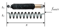 | [15] | ||
| Maxwell model | 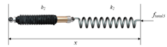 | [57] | ||
| Kelvin-Boltzmann model | 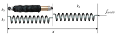 | [58] |
| Method | Technique | Degree of Freedom (DOF) | Sensitivity | Size | Cost | Advantages and Limitations | Online | References | ||
|---|---|---|---|---|---|---|---|---|---|---|
| Direct measurement method | Strain gauge | 1–6 | Force; Torque | Fine | Small | Low | Limited to temperature changes and electromagnetic noise; Drift and hysteresis | High strength; (Ethylene oxide or formaldehyde sterilization; Stainless protected) | Yes | [12,15,16,27,28,29,40,41,43,46,50,60,62,69,72,74,76,79,80,81,82,83,84,86,87,88,89,90,91,92,95,103] |
| Piezoelectric sensor | 1–3 | Force | Fine | Small | High | Limited to temperature changes and charge leakages; Not for static conditions because of drifting signal | High bandwidth; High power density; Great measurement range (Stainless protected) | Yes | [68,78,85,92,100,101,107] | |
| Optical sensor | 1–3 | Force; Torque | High | Small | High | Limited to cable deformation | Works in electromagnetic interference (EMI); Reproducibility; No hysteresis | Yes | [63,64,93,94,96,97] | |
| Indirect estimation method | Calculation method | 1–7 | Force; Torque | Multiple | Multiple | Multiple | Limited to a series of sensors; Complex structure | Acquires hard to detect forces | undetermined | [60,61,70,73,77] |
| Image-based method | 1 | Force | Low | No additional space | No additional cost | Limited to experiments equipped with imaging devices; No detailed analysis of force | Works in a high-temperature and high-pressure (HPHT) or corrosive environments; Easily acquires the total force | undetermined | [27,62,65,71,75,81,83,84,98,99,102,104] | |
| Actuator input method | Multiple | Force; Torque | Multiple | Multiple | Multiple | Limited to uncertainties; Requires compensation mechanisms; No detailed analysis of force | Easily acquires the total force | Yes | [45,67,70,108,109,110,111] | |
| Item | Effect Factor | Empirical Value or Detail | Correlations between the Influence Factors and Insertion Force | Reference | ||||
|---|---|---|---|---|---|---|---|---|
| Fstiffness | Ffriction | Fcutting | Fc+f | Ftotal | ||||
| Needle property | Diameter | 0.31–3.4 mm | √ | √ | √ | √ | [5,12,25,62,66,68,75,76,78,79,81,82,83,92,95,117,120,121,122,125,126,127,128] | |
| Bevel angle | 8–85° | √ | √ | √ | ||||
| Inclination angle λ | <30° | √ | ||||||
| Normal rake angle α | when λ > 70°, α < 10° | √ | ||||||
| Multi-bevel pen needle tip | 3,5 | √ | ||||||
| Tip type and edge | Diamond (Franseen); Beveled; Blunt; Conical; Sprotte; Tuohy | √ | ||||||
| Sharpness; Lubrication; Cannula; Asymmetrical type; Manufactory | √ | √ | √ | |||||
| Tissue characteristic | Living tissue | Human | √ | √ | √ | [5,12,15,25,27,28,42,43,44,56,62,69,74,75,76,82,83,112,113,119,122,126,127,128,129,130,133,134,135,136,137] | ||
| Animals: porcine, bovine, chicken, rabbit, turkey, sheep, canine | √ | √ | √ | |||||
| Organs: kidney, liver, heart, prostate, perineum, skin, muscle, fat, tendon, retina, vein, dura, vertebra, bone, brain, ligament, meninges | √ | √ | √ | |||||
| Artificial material | Polyvinyl alcohol (PVA), polyvinyl chloride (PVC), rubber, silicone gelatin, plastisol | |||||||
| Experimental pretreatment | In vivo or ex vivo; Live or dead; With or without skin Anesthetization; Moisture; Temperature; Gel elasticity; Multilayer | |||||||
| Individual difference | Suborgan or tissue interlace; Blood flow; Age; Gender; Body mass index (BMI); Ethnicity; Prior treatment; Stage of cancer; Gleason score; Pathological changes | |||||||
| Insertion method | Velocity | 0.0008–1000 mm/s | √ | √ | √ | √ | [5,25,28,40,42,49,67,69,74,75,76,79,90,92,115,116,118,123,124,125,131,132,139] | |
| Motion mode | Translational or rotational motion; Sinusoidal motion Oscillatory motion; Twisting-rotating motion | √ | √ | √ | ||||
| Drive mode | Interrupt or continuous; Manual or robotic | √ | √ | |||||
| Direction | 30° | √ | √ | |||||
| Location | Suborgan or tissue interlace; Blood flow | √ | √ | |||||
| Item | Typical Method | Advantages and Limitations | Applications | |||||
|---|---|---|---|---|---|---|---|---|
| Needle Deflection & Tissue Deformation | Path Planning & Navigation | Force Analysis | Online Force Control | |||||
| Data-based parameter identification | System response method; Frequency response method; Correlation method; Maximum likelihood method | Acquire data distribution characters; Reflect specific criteria; Data correlation analysis | Require high integrity; Huge workload; Offline estimation | √ | √ | √ | × | |
| Static system | Dynamic system | |||||||
| Time-invariant parameter identification | Weighted least-squares estimation; Constrained least-squares estimation; Truncated least-squares estimation; Total least-squares estimation; Nonlinear least-squares estimation | Least-squares estimation; Ordinary least-squares estimation; Biased least-squares estimation; Generalized least-squares method; Pre-filtering method; Neural network; Wavelet network | Characterize the entire system simply | Not well reflect the real situation of the whole system | √ | × | √ | × |
| Time-varying parameter identification | Recursive least-squares estimation; Square root filtering; Reduced-rank square root (RRSQRT) filtering; Extended Kalman filtering for the estimation | Recursive prediction-error estimation; Fixed-interval optimal smoothing; Extended Kalman filtering; Neural network; Wavelet network; Radial basis function neural network; Genetic algorithm; Evolutionary algorithm; Fuzzy logic algorithm; Times series analysis method | Online control; reflect the dynamic characteristics | Improve the complexity of analysis and research | √ | √ | √ | √ |
| Algorithm Classification | Workspace | Measured Variables | Modified Variables | Modulated Objectives | Advantages and Limitations | Applications | |||||
|---|---|---|---|---|---|---|---|---|---|---|---|
| Needle Deflection & Tissue Deformation | Path Planning & Navigation | Force Analysis | Online Force Control | ||||||||
| Active stiffness control | 1. Version one | Joint space | Position, force | Joint displacement, contact force | Joint stiffness matrix | See as a programmable spring; simple structure; good robustnes | Maximum controlled stiffness is influenced by the stability; require force sensor; successful in very specific tasks | √ | √ | √ | √ |
| 2. Version two | Task space a | Position error, contact force | Stiffness matrix | ||||||||
| Impedance control | 1. Basic impedance control | Task space | Position, velocity, force | Position and velocity error, contact force | Impedance | Direct control of the force between the end actuators and the environment; realize compliance control | Requires a lot of task planning; Need to switch between force control and position control; | √ | √ | √ | √ |
| 2. Position-based impedance control | Modified desired trajectory, contact force | ||||||||||
| Admittance control | Force | Force error | Admittance | Direct control of the force between the end actuators and the environment; realize compliance control | Select appropriate parameters to ensure the stability | √ | √ | √ | √ | ||
| Hybrid control | 1. Hybrid position/force | {P} b | Position | Position error | Position | The position control and force control can be separately considered; Flexible to choose the strategy | Computational complexity; Location coordinates need to be determined by the environmental constraint equation | √ | √ | √ | √ |
| {F} c | Force | Force error | Force | ||||||||
| 2. Hybrid impedance | {P} | Force | Velocity error | Zmp d | |||||||
| {F} | Force error | Zmf e | |||||||||
| Explicit force control | PI, PD, PID, etc. | Task space | Force | Force error | Desired force FD | Direct force feedback | No postion feedback | √ | √ | √ | √ |
| Implicit force control | Task space | Position | Position error | Predefined stiffness | The position is controlled by the position for a desired force | No force feedback | √ | √ | √ | √ | |
© 2018 by the authors. Licensee MDPI, Basel, Switzerland. This article is an open access article distributed under the terms and conditions of the Creative Commons Attribution (CC BY) license (http://creativecommons.org/licenses/by/4.0/).
Share and Cite
Yang, C.; Xie, Y.; Liu, S.; Sun, D. Force Modeling, Identification, and Feedback Control of Robot-Assisted Needle Insertion: A Survey of the Literature. Sensors 2018, 18, 561. https://doi.org/10.3390/s18020561
Yang C, Xie Y, Liu S, Sun D. Force Modeling, Identification, and Feedback Control of Robot-Assisted Needle Insertion: A Survey of the Literature. Sensors. 2018; 18(2):561. https://doi.org/10.3390/s18020561
Chicago/Turabian StyleYang, Chongjun, Yu Xie, Shuang Liu, and Dong Sun. 2018. "Force Modeling, Identification, and Feedback Control of Robot-Assisted Needle Insertion: A Survey of the Literature" Sensors 18, no. 2: 561. https://doi.org/10.3390/s18020561
APA StyleYang, C., Xie, Y., Liu, S., & Sun, D. (2018). Force Modeling, Identification, and Feedback Control of Robot-Assisted Needle Insertion: A Survey of the Literature. Sensors, 18(2), 561. https://doi.org/10.3390/s18020561