Abstract
SF6 decomposition components detection is a key technology to evaluate and diagnose the insulation status of SF6-insulated equipment online, especially when insulation defects-induced discharge occurs in equipment. In order to detect the type and concentration of SF6 decomposition components, a Ni-modified carbon nanotube (Ni-CNT) gas sensor has been prepared to analyze its gas sensitivity and selectivity to SF6 decomposition components based on an experimental and density functional theory (DFT) theoretical study. Experimental results show that a Ni-CNT gas sensor presents an outstanding gas sensing property according to the significant change of conductivity during the gas molecule adsorption. The conductivity increases in the following order: H2S > SOF2 > SO2 > SO2F2. The limit of detection of the Ni-CNT gas sensor reaches 1 ppm. In addition, the excellent recovery property of the Ni-CNT gas sensor makes it easy to be widely used. A DFT theoretical study was applied to analyze the influence mechanism of Ni modification on SF6 decomposition components detection. In summary, the Ni-CNT gas sensor prepared in this study can be an effective way to evaluate and diagnose the insulation status of SF6-insulated equipment online.
1. Introduction
Due to the strong insulation strength and electronegativity of SF6 gas, it has been widely used as filling gas in insulated equipment, such as SF6-insulated high-voltage switchgear (GIS), SF6-insulated transmission lines (GIL), and SF6-insulated circuit breakers (GCB) [1,2,3]. However, insulation defects inevitably occur in SF6-insulated equipment, which induces SF6 to decompose into various decomposition components: SO2, H2S, SOF2, and SO2F2 under electric discharge [4,5,6,7]. In addition, the existence of insulation defects and SF6 decomposition dramatically reduce the insulation strength of SF6-insulated equipment [8]. A lot of methods have been studied to detect the insulation defects, including the ultra-high frequency method (UHF) [9,10], the transient earth voltage method (TEV) [11], the ultrasonic method [12],the gas chromatographic method [13], and the gas sensor detection method [14]. However, UHF, TEV, and the ultrasonic method are easily affected by interference signals, and the gas chromatographic method is an offline detection method. Because of the non-contact, high accuracy, and low detection limit features of gas sensors, the gas sensor detection method has been an effective way to realize the online detection of SF6-insulated equipment based on SF6 decomposition components detection [15,16].
One dimensional carbon nanotube (CNT) material has attracted extensive study due to its outstanding characteristics [17,18], such as large specific surface area and good electrical properties. It is demonstrated that CNTs shows excellent gas sensing performance to gases [19,20], making it an effective detection method used in environmental, industrial, and military fields [21,22]. Li et al. fabricated single-wall carbon nanotube (SWNT) based gas sensors on interdigitated gold electrodes; its detection limit reaches 44 ppb for NO2 and 262 ppb for nitrotoluene at room temperature [19]. Chopra et al. reported that multi-wall carbon nanotube (MWCNT) and polymer composites exhibited excellent sensitivity and selectivity to NH3 and NO2 at room temperature [23]. Surface modification based on metal particles can greatly improve the gas sensitivity and selectivity of CNTs. Penza et al. verified that the functionalization of Pt and Pd nanoclusters on the MWCNT surface significantly improved its detection limit to sub-ppm level upon NO2, H2S, NH3, and CO detection [24]. Although the development of CNT gas sensors has made a remarkable improvement in common gas detection, there are few reports about its application in the field of SF6 decomposition components detection.
Here, Nickel functionalized CNTs (Ni-CNTs) are adopted as the gas sensing material to detect the characteristic SF6 decomposition components: SO2, H2S, SOF2 and SO2F2. Experimentally, the Ni-CNT gas sensor is prepared by the drop-casting method, which significantly reduces the preparation cost and benefits for industrial-scale production. In addition, the gas sensing mechanism of Ni-CNTs to the characteristic SF6 decomposition components is studied by density functional theory (DFT) calculation. We conclude that the Ni-CNT gas sensor can be an effective way to detect the insulation defects and diagnose the running status of SF6-insulated equipment online.
2. Material and Methods
2.1. Synthesis of Ni-CNT Gas Sensor
Ni-CNTs (inner diameter: 5–10 nm, external diameter: 10–20 nm, and length: 10–30 μm) were bought from Aladdin Reagent Corporation (Shanghai, China). Figure 1a shows the interdigitated Cu electrodes; Cu electrodes (thickness: 30 μm, gap: 0.2 mm) were fabricated on epoxy resin as a substrate of the Ni-CNT gas sensor. Ni-CNTs were dispersed in dimethylformamide (DMF) to form a solution of 0.025 mg/mL by the following steps: soak 6 h, then ultrasonic treat 2 h. The solution was sprayed onto the surface of the Cu electrodes at 80 °C to accelerate the evaporation of DMF. As shown in Figure 1b, Ni-CNTs evenly distribute on the surface of the Cu electrodes, which benefits the gas molecule adsorption and desorption process.
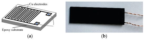
Figure 1.
(a) Interdigitated Cu electrodes, (b) the prepared Ni-modified carbon nanotube (Ni-CNT) gas sensor.
2.2. Material Characterization and Gas Sensing Measurement
Transmission electron microscopy (TEM) was tested by FEI Tecnai G2 F20 S-TWIN at 200 kV. The gas-sensing detection system was composed of standard gases (SO2, H2S, SOF2, and SO2F2), the gas distribution system, the gas sensing chamber, and an electrochemical workstation. The concentration of standard gases was 400 ppm with N2 as the background gas. The standard gases were diluted to different concentrations: 1, 10, 50, 100, 200, 300, and 400 ppm by the gas distribution system. Then, the diluted gases were led to the closed gas chamber. The resistance of the Ni-CNT gas sensor was measured by the electrochemical workstation at room temperature and ambient pressure. The gas response (GR) was defined by Equation (1). In which, Ri is the initial electric resistance of the Ni-CNT gas sensor in dry synthesis air and Rf is the resistance of the sensor in SF6 decomposition components’ atmosphere. In addition, the sensitivity (S) of the Ni-CNT gas sensor was defined by Equation (2), where CT was the concentration of tested gas.
2.3. DFT Calculation
The DFT calculations were performed using Dmol3 package of materials studio. The structure of (8, 0) Ni-CNTs was built by substituting a carbon atom by one Ni atom. In addition, a 20 × 20 × 8.5 Å periodic-boundary supercell was built to avoid the interference of adjacent cells. Then, the optimized adsorption structures of SO2, H2S, SOF2, and SO2F2 on the surface of Ni-CNTs were calculated with different initial gas positions. The Perdew–Burke–Ernzerhof (PBE) function generalized gradient approximation was adopted to treat the exchange-correlation potential. The convergence criterion for energy and force was set at 10−5 Ha and 2 × 10⁻³ Ha/Å, respectively. The Brillouin zone was sampled with 1 × 1 × 2 Monkhorst–Pack mesh. The adsorption energy (Eads) of the molecules adsorbed on Ni-CNTs was defined by the following Equation (3):
where Egas/suf was the energy of gas adsorbed CNTs, Esurf and Egas were the energy of isolated Ni-CNTs and molecules of SF6 decomposition components.
The electron density distribution was obtained by Mulliken population analysis. The charge transfer (Qt) in the adsorption process was defined by Equation (4), where Qiso and Qads were the respective total charge of gas molecules before and after adsorption.
3. Results and Discussion
3.1. Preparation and Gas Sensing Property of Ni-CNT Gas Sensor
As per the formation mechanism of Ni-CNTs shown in Figure 2a, it is important to make sure that Ni particles evenly decorate onto the outside wall of intrinsic CNTs, which plays a key role to the gas-sensing properties of the prepared Ni-CNT gas sensor. As per the typical TEM images shown in Figure 2b–d with different magnifications, Ni-CNTs evenly disperse on the surface of the prepared gas sensor. Hence, there will be large, hollow structures for gas diffusion among the Ni-CNTs, which not only increase the adsorption capacity, but reduce the adsorption and desorption time. Ni nanoparticles mainly distribute on the outside wall of CNTs due to the long length and closed structure of CNTs (about 30 μm). The small diameter of Ni-CNTs (about 20 nm) signifies large curvature and high surface activity. Besides, the surface defects that existed on the surface of CNTs provide the adsorption sites for gas molecules. As a result, Ni nanoparticles evenly decorate on the surface of CNTs with their size distinctly smaller than the diameter of CNTs. Ni nanoparticles act as the active sites for gas molecule adsorption, which effectively enhances the gas-sensing properties of CNT-based sensors.
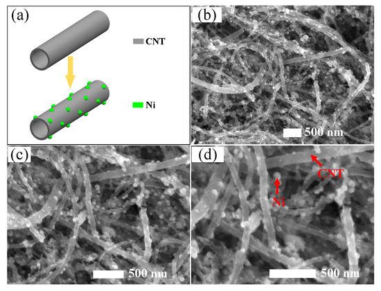
Figure 2.
(a) The formation mechanism of Ni-CNTs, (b–d) structure characterization of Ni-CNTs.
Considering the concentration range of SF6 decomposition components generated in SF6-insulated equipment reported in previous studies [4,25], a series of SF6 decomposition components concentrations, 1, 10, 50, 100, 200, 300, and 400 ppm, were prepared to analyze the gas-sensing performance of the Ni-CNT gas sensor. As shown in Figure 3, the resistance of the gas sensor significantly reduces when it contacts SF6 decomposition components [26,27,28,29]. The Ni-CNT gas sensor presents a large gas response to SF6 decomposition components at room temperature and ambient pressure due to the catalytic property of evenly distributed Ni nanoparticles. Furthermore, the CNT sensor presents a fast gas response because of the large gas diffusion channel among Ni-CNTs, which also implies a fast gas-sensing recovery speed. The resistance rapidly reduces when the sensor just contacts the SF6 decomposition components, because the gas molecules quickly interact with the gas-sensing material on the surface of the Ni-CNT gas sensor. Meanwhile, the reduction speed gradually decreased as the gas diffusion rate sharply reduced with diffusion depth in the sensor film.
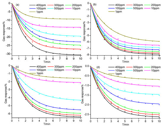
Figure 3.
Gas response of the Ni-CNT gas sensor to different concentrations of SF6 decomposition components: (a) H2S, (b) SOF2, (c) SO2, and (d) SO2F2 at room temperature and ambient temperature.
As shown in Figure 3, it takes about 10 min for the gas response to reach a steady state. The variation of gas response is greatly influenced by the concentration of SF6 decomposition components. For instance, the difference of gas response as the gas concentration increases from 300 to 400 ppm is smaller than that of 200 to 300 ppm. Comparing the value of gas responses shown in Figure 3a–d under the same gas concentration, the variation of gas responses is placed in the following order: H2S > SOF2 > SO2 > SO2F2. The largest value of gas response to H2S is −30.54% at the concentration of 400 ppm, and the value of the gas response still reached −9.50% at the lowest concentration (1 ppm) as shown in Figure 3a. The high gas response mainly comes from the strong interaction between Ni-CNTs and H2S molecules at the Ni atom functionalized sites, which contributes to the detection of the H2S component up to sub-ppm level. According to Figure 3b, the gas response of the Ni-CNT gas sensor to SOF2 changes a little under different gas concentrations. The gas responses at 400 ppm and 1 ppm are −8.04% and −5.91%, respectively. On the contrary, different concentrations of SO2 leads to a significant change of gas response, as shown in Figure 3c. The value of gas response increases from −1.62% (1 ppm) to −6.37% (400 ppm). Although Ni atom functionalization on the Ni-CNT surface enhances its adsorption to SO2F2, the Ni-CNT gas sensor was still not sensitive to SO2F2. As shown in Figure 3d, the gas responses to SO2F2 are −2.65% and −0.7% at 400 ppm and 1 ppm, respectively. In summary, the Ni-CNT gas sensor shows a high gas response to SF6 decomposition components, and its high gas-sensing selectivity can be used to identify the gas types of SF6 decomposition components produced in SF6-insulated equipment, making it suitable to detect the insulation defects and diagnose the running status of SF6 insulated equipment online.
Table 1 shows the comparison of the limit of detection (LOD) for different sensors to SF6 decomposition components reported in recent studies, including the most studied gas-sensing material: CNTs, graphene, and TiO2 nanotubes. In this study, the highest gas response of the Ni-CNT sensor studied in this work reaches −9.5% upon 1 ppm H2S measurement, which was slightly higher than that of reported CNT-based gas sensors. Meanwhile, a TiO2-based gas sensor usually needs a high working temperature to receive a high gas response to SF6 decomposition components. It was reported that the LOD of Au-Graphene was only 50 ppm with a gas response of 18.75% to H2S [28]. Therefore, the Ni-CNT sensor obviously presents advantages in high gas response and low working temperature.

Table 1.
The limit of detection (LOD) of different gas sensors to SF6 decomposition components. RT represents room temperature. CNTs: carbon nanotubes.
To demonstrate the reusability of the prepared Ni-CNT gas sensor, we have done multiple measurements to obtain its response and recovery properties to different types of SF6 decomposition components at the same concentration (400 ppm). As shown in Figure 4, the flow rate of SF6 decomposition components is 100 sccm during the gas-sensing process, and the N2 flow is used in the recovery process with a flow rate of 200 sccm. In addition, the illumination of UV light is applied to enhance the recovery process as it greatly increases the molecular vibration of SF6 decomposition components. Gas-in and N2 + UV represent the flow of SF6 decomposition components (SO2, H2S, SOF2, and SO2F2) and the flow of pure N2 flow with UV illumination, respectively. Simultaneously, N2 flow transfers the desorbed gas from the surface of Ni-CNTs and avoids re-adsorption. The Ni-CNT gas sensor still keeps a good gas response to SO2, H2S, SOF2, and SO2F2 after multiple gas adsorption and desorption detections, as the gas response changes little with measurement times. The value of gas response reduces from initially −30.54% to −28.13% upon H2S detection. In addition, the change of gas response to SOF2, SO2, and SO2F2 was 0.55% (from −8.04% to −7.49%), 0.69% (from −6.37% to 5.68%), and 0.31% (from −2.65% to −2.34%) after three lots of measurements, which is much less than the change of gas response to H2S.
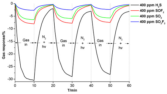
Figure 4.
The gas response and recovery properties of the Ni-CNT gas sensor to SF6 decomposition components.
Figure 5a shows the change of gas response with the increase of concentration of SF6 decomposition components. Upon H2S and SOF2 detection, the gas response sharply enhances when gas concentration increases from 1 to 50 ppm, and then tends to linearly increase under high gas concentration of detected gases, from 50 to 400 ppm. This also demonstrates that the Ni-CNT sensor is sensitive to H2S and SOF2. Upon SO2 and SO2F2 detection, the increase of the gas response shows an exponential growth trend. Figure 5b shows the change of sensitivity to SF6 decomposition components; the sensitivity presents an exponential attenuation from 1 to 400 ppm, because it tends to be saturated at a high gas concentration. The attenuation speed is listed in the following order: H2S > SOF2 > SO2 > SO2F2 at the same gas concentration.
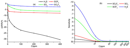
Figure 5.
(a) The change of gas response, and (b) the change of sensitivity with the increase of concentration of SF6 decomposition components.
3.2. DFT Study of the Ni-CNT Gas Sensor
DFT study is used to analyze the adsorption properties of Ni-CNTs to SF6 decomposition components: SO2, H2S, SOF2, and SO2F2. As Ni nanoparticles modified on the CNT surface always exist as clusters, single and double Ni atom-doped CNT structures are built to reflect the influence of Ni nanoparticles, represented by 1Ni-CNTs and 2Ni-CNTs. Figure 6 and Table 2 show the most stable adsorption structures and corresponding data for one gas molecule adsorption on Ni-CNTs. It is found that all the gas molecules tend to adsorb around Ni atoms due to its high adsorption activity. SO2, H2S, and SOF2 interact with Ni-CNTs with physisorption. Due to the polyvalent properties of the sulfur atom, the chemisorption between SO2F2 and the Ni-CNT surface leads to the structure break of SO2F2 in the adsorption process, reducing the reusability of the CNT gas sensor as it impedes the gas molecule desorption. The H2S molecule interacts with Ni-CNTs by sulfur atoms. The nearest adsorption distance for H2S reduces from 2.33 Å to 2.15 Å when the doped Ni atoms increase from single to double. SO2 and SOF2 molecules interact with Ni-CNTs by oxygen atoms rather than sulfur atoms because the sulfur atom has already built a strong covalent bond with two oxygen atoms or two fluorine atoms. The nearest adsorption distance for SO2 and SOF2 on 2Ni-CNTs are 1.88 Å and 1.94 Å, respectively. The nearest distance from the SO2F that breaks from SO2F2 to Ni-CNTs is 1.86 Å on 2Ni-CNTs. Except for H2S adsorption, electrons transfer from Ni-CNTs to gas molecules in the adsorption process as Ni atoms act as the electron donor. The large adsorption energy for all of the gas molecules shows that Ni-doped CNTs are an effective gas-sensing material to detect the SF6 decomposition components.
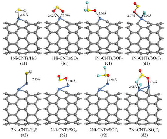
Figure 6.
Optimized geometries of SF6 decomposition components adsorbed Ni-doped CNTs, distances in Å.
Table 2.
Interaction distance (d), adsorption energy Eads, charge transfer Qt of SF6 decomposition components adsorbed Ni-doped CNTs.
Generally, gas sensors detect the concentration of contacted gas by measuring the change of conductivity during the adsorption process. Density of states (DOS) is one of the effective ways to analyze the change of conductivity upon SO2, H2S, SOF2, and SO2F2 adsorption. As shown in Figure 7, the DOS around Fermi level for H2S, H2S, and SOF2 adsorptions obviously increase in different degrees, which leads to the corresponding change of conductivity. The change of conductivity has just verified that the Ni-CNT sensor shows a high gas response to H2S, H2S, and SOF2. Meanwhile, the inconspicuous change of DOS upon SO2F2 adsorption slightly increases the conductivity of the adsorption system, which is consistent with the experimental study.
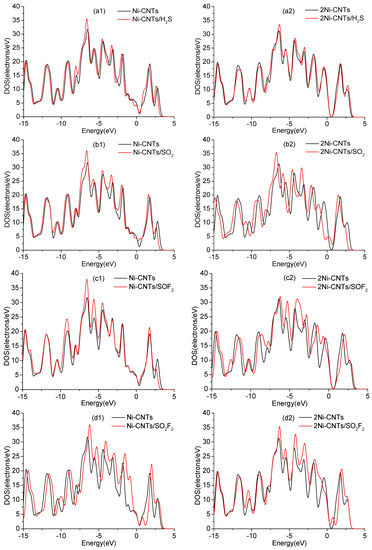
Figure 7.
Density of states (DOS) of Ni-CNTs, 2Ni-CNTs, and gas adsorbed Ni-CNTs: (a1–d1) represent gas adsorption on Ni-CNTs, (a2–d2) represent gas adsorption on 2Ni-CNTs.
In DOS analysis, the change of conductivity upon H2S adsorption is less than SO2, SOF2, and SO2F2 adsorption, based on the calculation condition that the default temperature is 0 K. However, the detection temperature has increased to ambient temperature, which distinctly enhances the reaction activity of the S atom. In addition, S in H2S is much more active than that in SO2, SOF2, and SO2F2 because it only builds two monovalences with H atoms. As a result, the change of conductivity for a single H2S molecule is the largest among four gas molecule adsorptions in the experiment.
4. Conclusions
This study introduces Ni modification on the CNT surface for the sensitive and selective detection of SF6 decomposition components: SO2, H2S, SOF2, and SO2F2. The TEM results show that Ni particles evenly distribute on the surface of CNTs. The prepared Ni-CNT gas sensor shows high gas sensitivity as its LOD reaches 1 ppm to SF6 decomposition components. The sensitivity of the Ni-CNT gas sensor is placed in the following order: H2S > SOF2 > SO2 > SO2F2. In addition, the Ni-CNT gas sensor shows good gas-sensing recovery property, which makes it easy to be widely used. DFT theoretical study results verify that conductivity of the adsorption system significantly changes when SF6 decomposition components interact with Ni-CNTs. Thus, our finding is certainly beneficial to broaden the perspective of Ni-CNT gas sensor applications in evaluating and diagnosing the insulation status of SF6-insulated equipment online.
Author Contributions
Y.G. and X.Z. proposed the project and analyzed the simulation results. Y.G. contributed to the experimental detection. C.T. and Q.Z. did DFT simulations. P.L. and S.W. did the analysis of the data and gave some revision of the manuscript. All authors read and approved the final manuscript.
Funding
This study was supported by the National Key R&D Program of China (Grant No. 2017YFB0902700, 2017YBF0902702), and the Fundamental Research Funds for the Central Universities (Grant No. SWU118030).
Conflicts of Interest
The authors declare no conflict of interest.
References
- Tang, J.; Xu, Z.R.; Zhang, X.X.; Sun, C.X. GIS partial discharge quantitative measurements using UHF microstrip antenna sensors. In Proceedings of the 2007 Annual Report—Conference on Electrical Insulation and Dielectric Phenomena, Vancouver, BC, Canada, 14–17 October 2007. [Google Scholar]
- Völcker, O.; Koch, H. Insulation co-ordination for gas-insulated transmission lines (GIL). IEEE Trans. Power Delivery 2000, 16, 122–130. [Google Scholar] [CrossRef]
- Liu, J.; Huang, G.M.; Ma, Z. A Novel intelligent high voltage SF6 circuit breaker. In Proceedings of the IEEE PES General Meeting, Providence, RI, USA, 25–29 July 2010. [Google Scholar]
- Van Brunt, R.J. Production Rates for Oxyfluorides SOF2, SO2F2, and SOF4 in SF6 Corona Discharges. Available online: https://nvlpubs.nist.gov/nistpubs/jres/090/3/V90-3.pdf#page=13 (accessed on 13 October 2018).
- Walters, J.P. Spark discharge: Application multielement spectrochemical analysis. Science 1977, 198, 787–797. [Google Scholar] [CrossRef] [PubMed]
- Sauers, I. By-product formation in spark breakdown of SF6/O2 mixtures. Plasma Chem. Plasma Process. 1988, 8, 247–262. [Google Scholar] [CrossRef]
- Zhang, X.; Gui, Y.; Dai, Z. A simulation of Pd-doped SWCNT used to detect SF6 decomposition components under partial discharge. Appl. Surf. Sci. 2014, 315, 196–202. [Google Scholar] [CrossRef]
- Zeng, F.; Ju, T.; Zhang, X.; Pan, J. Influence regularity of trace H2O on SF6 decomposition characteristics under partial discharge of needle-plate electrode. IEEE Trans. Dielectr. Electr. Insul. 2015, 22, 287–295. [Google Scholar] [CrossRef]
- Judd, M.D.; Yang, L.; Hunter, I.B.B. Partial discharge monitoring of power transformers using UHF sensors. Part I: sensors and signal interpretation. IEEE Electr. Insul. Mag. 2005, 21, 5–14. [Google Scholar] [CrossRef]
- Judd, M.D.; Yang, L.; Hunter, I.B.B. Partial discharge monitoring for power transformer using UHF sensors. Part 2: field experience. IEEE Electr. Insul. Mag. 2005, 21, 5–13. [Google Scholar] [CrossRef]
- Jennings, E.; Collinson, A. A partial discharge monitor for the measurement of partial discharges in a high voltage plant by the transient earth voltage technique. In Proceedings of the 1993 International Conference on Partial Discharge, Canterbury, UK, 28–30 September 1993. [Google Scholar]
- Kweon, D.J.; Chin, S.B.; Kwak, H.R.; Kim, J.C. The analysis of ultrasonic signals by partial discharge and noise from the transformer. IEEE Trans. Power Delivery 2005, 20, 1976–1983. [Google Scholar] [CrossRef]
- Tang, J.; Liu, F.; Zhang, X.X.; Meng, Q.H.; Zhou, J.B. Partial discharge recognition through an analysis of SF6 decomposition products part 1: Decomposition characteristics of SF6 under four different partial discharges. IEEE Trans. Dielectr. Electr. Insul. 2012, 19, 29–36. [Google Scholar] [CrossRef]
- Ding, W.D.; Hayashi, R.; Suehiro, J.; Zhou, G.; Imasaka, K.; Hara, M. Calibration methods of carbon nanotube gas sensor for partial discharge detection in SF/sub 6. IEEE Trans. Dielectr. Electr. Insul. 2006, 13, 353–361. [Google Scholar] [CrossRef]
- Minagawa, T.; Kawada, M.; Yamauchi, S.; Kamei, M.; Nishida, C. Development of SF6 decomposition gas sensor. Surf. Coat. Technol. 2003, 169, 643–645. [Google Scholar] [CrossRef]
- Hanabusa, K.; Takata, S.; Fujisaki, M.; Nomura, Y.; Suzuki, M. Fluorescent gelators for detection of explosives. Bull. Chem. Soc. Jpn. 2016, 89, 1391–1401. [Google Scholar] [CrossRef]
- Besteman, K.; Lee, J.O.; Wiertz, F.G.M.; Heering, H.A.; Dekker, C. Enzyme-coated carbon nanotubes as single-molecule biosensors. Nano Lett. 2003, 3, 727–730. [Google Scholar] [CrossRef]
- Qi, P.; Vermesh, O.; Grecu, M.; Javey, A.; Wang, Q.; Dai, H.; Peng, S.; Cho, K.J. Toward large arrays of multiplex functionalized carbon nanotube sensors for highly sensitive and selective molecular detection. Nano Lett. 2003, 3, 347–351. [Google Scholar] [CrossRef]
- Jing, L.; Lu, Y.; Ye, Q.; Cinke, M.; Han, J.; Meyyappan, M. Carbon nanotube sensors for gas and organic vapor detection. Nano Lett. 2003, 3, 929–933. [Google Scholar]
- Komiyama, M.; Mori, T.; Ariga, K. Molecular imprinting: Materials nanoarchitectonics with molecular information. Bull. Chem. Soc. Jpn. 2018, 91, 1075–1111. [Google Scholar] [CrossRef]
- Osica, I.; Imamura, G.; Shiba, K.; Ji, Q.; Shrestha, L.K.; Hill, J.P.; Kurzydłowski, K.J.; Yoshikawa, G.; Ariga, K. Highly Networked Capsular Silica-Porphyrin Hybrid Nanostructures as Efficient Materials for Acetone Vapor Sensing. ACS Appl. Mater. Interfaces 2017, 9, 9945–9954. [Google Scholar] [CrossRef] [PubMed]
- Zhang, Y.; Yuan, S.; Day, G.; Wang, X.; Yang, X.; Zhou, H.C. Luminescent sensors based on metal-organic frameworks. Coord. Chem. Rev. 2018, 354, 28–45. [Google Scholar] [CrossRef]
- Chopra, S.; Mcguire, K.; Gothard, N.; Rao, A.M.; Pham, A. Selective gas detection using a carbon nanotube sensor. Appl. Phys. Lett. 2003, 83, 2280–2282. [Google Scholar] [CrossRef]
- Penza, M.; Rossi, R.; Alvisi, M.; Cassano, G.; Signore, M.A.; Serra, E.; Giorgi, R. Pt-and Pd-nanoclusters functionalized carbon nanotubes networked films for sub-ppm gas sensors. Sens. Actuators, B chem. 2008, 135, 289–297. [Google Scholar] [CrossRef]
- Tang, J.; Rao, X.; Zeng, F.; Cai, W.; Cheng, L.; Zhang, C. Influence mechanisms of trace H2O on the generating process of SF6 spark discharge decomposition components. Plasma Chem. Plasma Process. 2017, 37, 1–16. [Google Scholar] [CrossRef]
- Zhang, X.; Chen, Q.; Hu, W.; Zhang, J. A DFT study of SF6 decomposed gas adsorption on an anatase (101) surface. Appl. Surf. Sci. 2013, 286, 47–53. [Google Scholar] [CrossRef]
- Zhang, X.; Chen, Q.; Tang, J.; Hu, W.; Zhang, J. Adsorption of SF6 decomposed gas on anatase (101) and (001) surfaces with oxygen defect: A density functional theory study. Sci. Rep. 2014, 4, 4762. [Google Scholar] [CrossRef] [PubMed]
- Zhang, X.; Yu, L.; Wu, X.; Hu, W. Experimental sensing and density functional theory study of H2S and SOF2 adsorption on Au-modified graphene. Adv. Sci. 2015, 2, 1500101. [Google Scholar] [CrossRef] [PubMed]
- Zhang, X.; Dong, X.; Gui, Y. Theoretical and experimental study on competitive adsorption of SF6 decomposed components on Au-modified anatase (101) surface. Appl. Surf. Sci. 2016, 387, 437–445. [Google Scholar] [CrossRef]
- Zhang, X.; Luo, C.; Tang, J. Sensitivity characteristic analysis of adsorbent-mixed carbon nanotube sensors for the detection of SF6 decomposition products under PD conditions. Sensors 2013, 13, 15209. [Google Scholar] [CrossRef] [PubMed]
- Star, A.; Joshi, V.; Skarupo, S.; Thomas, D.; Gabriel, J.C.P. Gas sensor array based on metal-decorated carbon Nanotubes. J. Phys. Chem. B 2006, 110, 21014–21020. [Google Scholar] [CrossRef] [PubMed]
- Zhang, X.; Tie, J.; Zhang, J. A Pt-doped TiO2 nanotube arrays sensor for detecting SF6 decomposition products. Sensors 2013, 13, 14764. [Google Scholar] [CrossRef] [PubMed]
© 2018 by the authors. Licensee MDPI, Basel, Switzerland. This article is an open access article distributed under the terms and conditions of the Creative Commons Attribution (CC BY) license (http://creativecommons.org/licenses/by/4.0/).