Detecting Traversable Area and Water Hazards for the Visually Impaired with a pRGB-D Sensor


Abstract
:
1. Introduction
2. Related Work
- The approach is able to detect traversable area and water hazard simultaneously, which prevents colliding into obstacles and stepping in water areas during navigation.
- The approach takes into account of the attitude angles of the sensor, which enables accurate detection with the continuous movement of the wearable prototype during navigation.
- The approach combines the detection of water hazard with the detection of traversable area, which decreases the computing cost and reduces water area detection error in scenarios such as sky regions and edges of buildings.
3. Approach
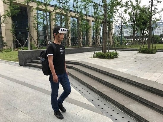
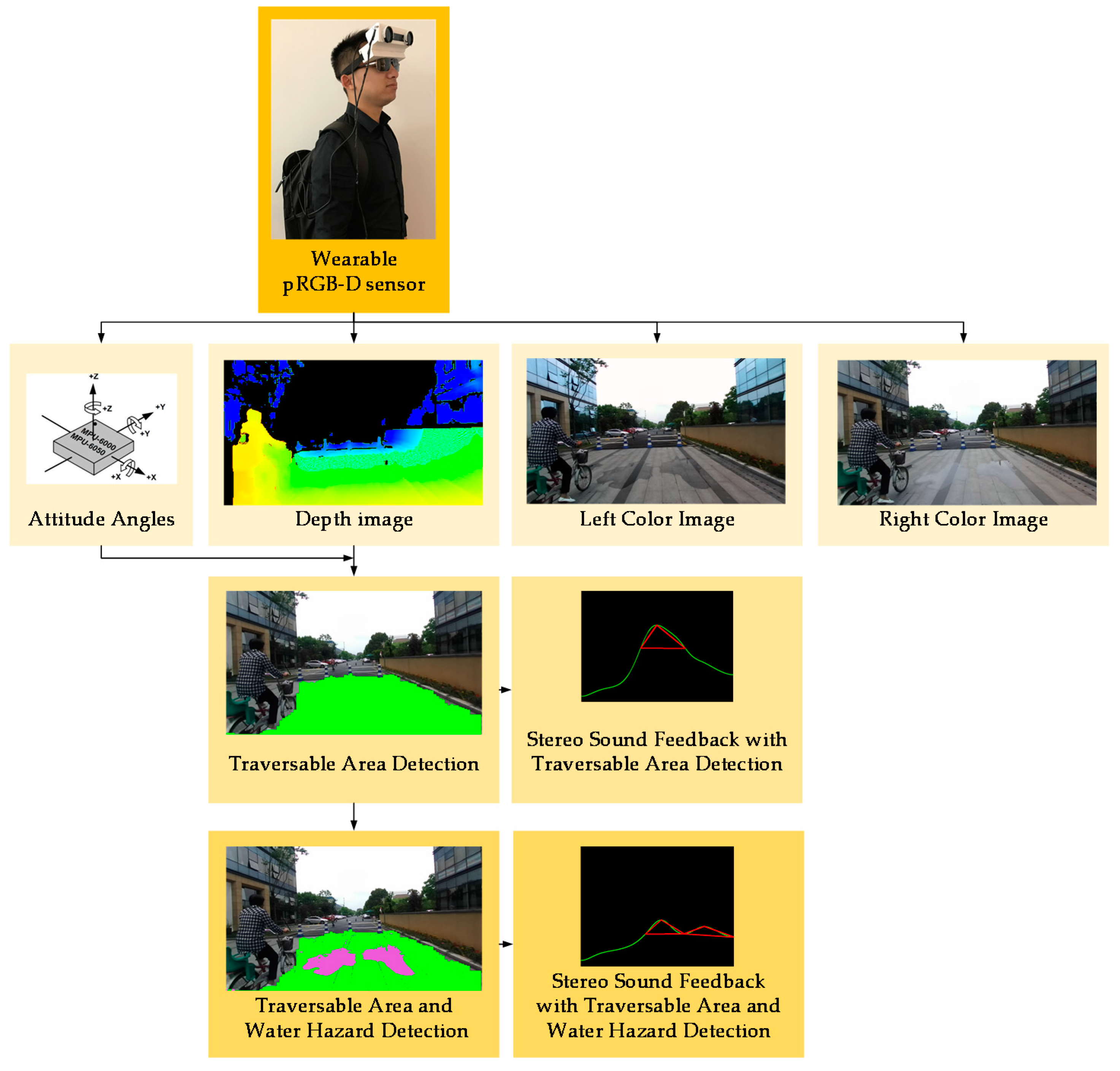
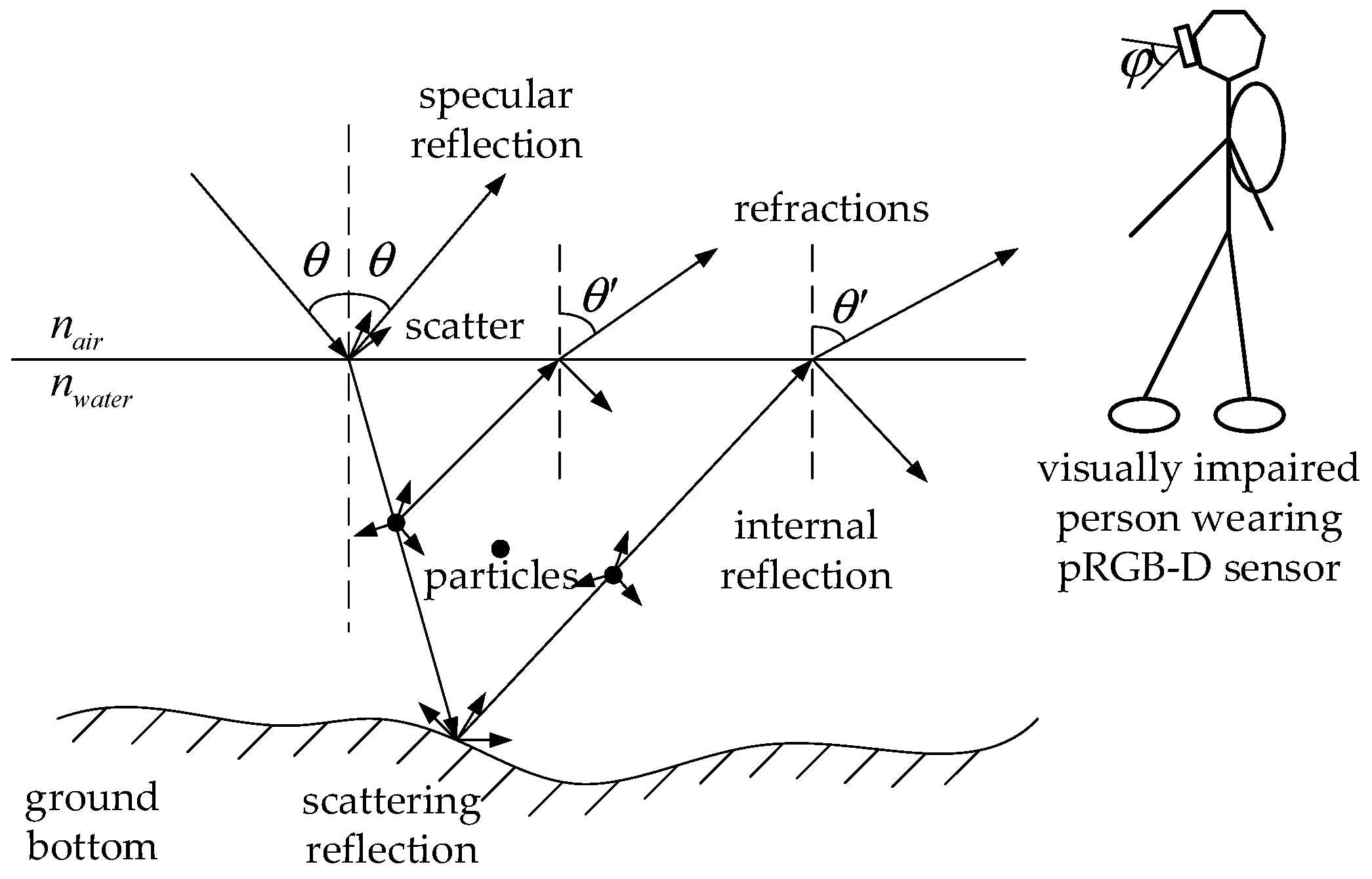
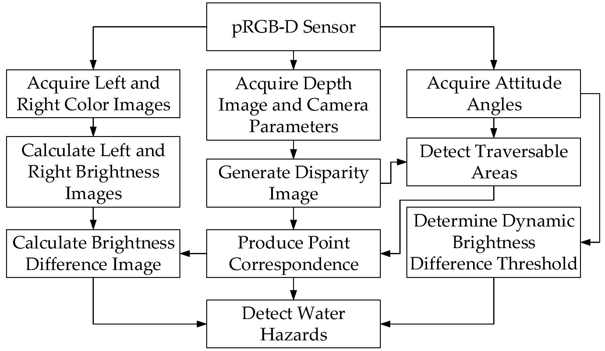
3.1. pRGB-D Sensor
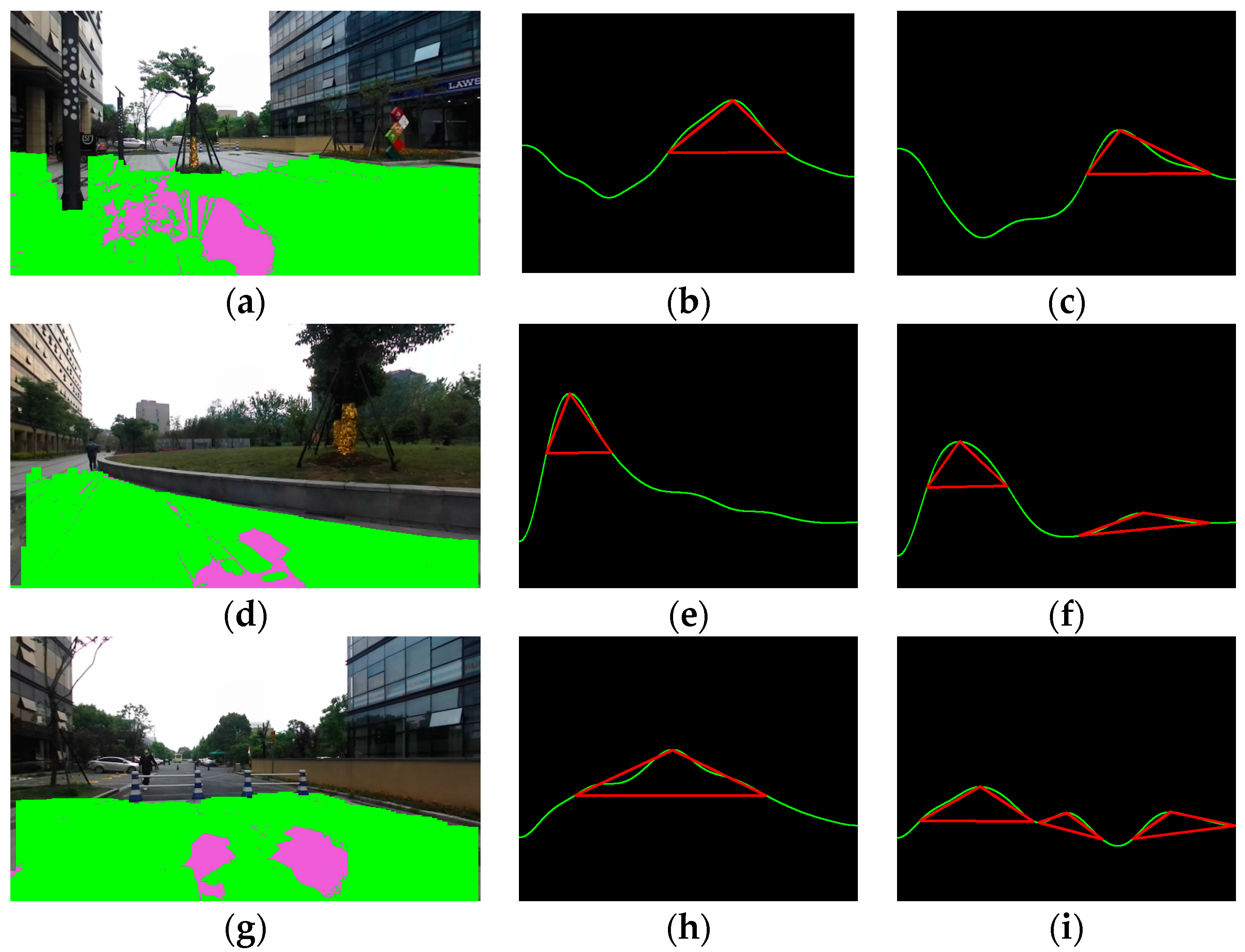
3.2. Traversable Area Detection
3.3. Water Hazard Detection and Stereo Sound Feedback
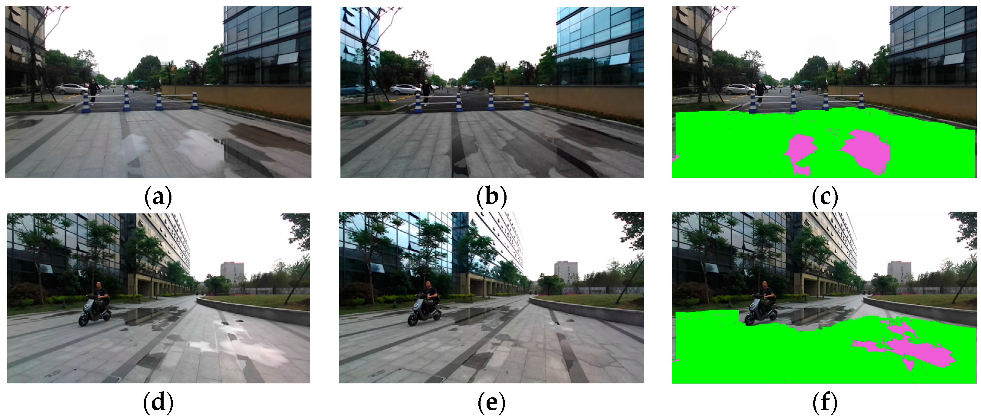
- Pixel G is classified as traversable in the process as presented in Section 3.2, where traversable area is detected with depth and attitude information.
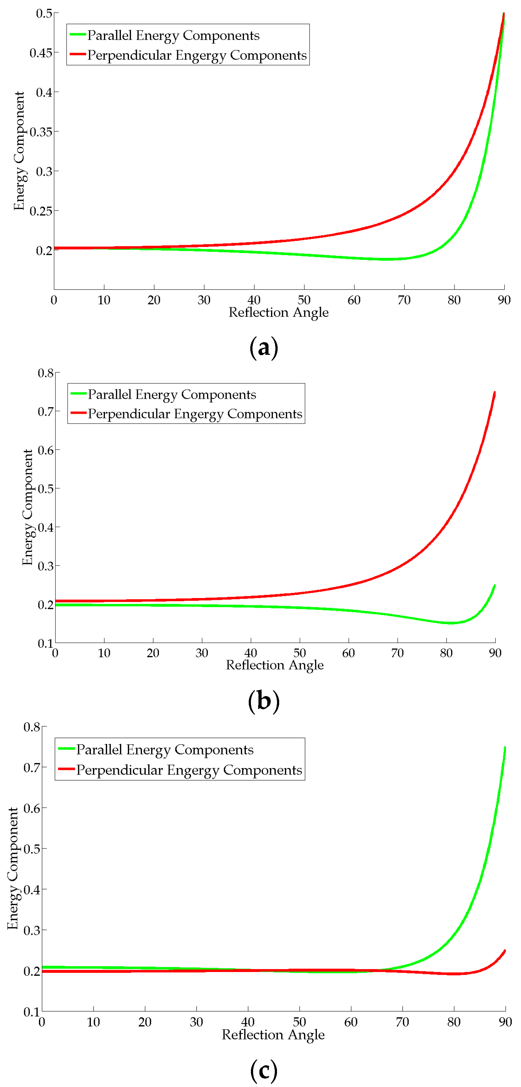
- , where is the dynamic threshold of polarization difference set with the derivation in Section 3.1 and varies with the rolling angle of the pRGB-D sensor.
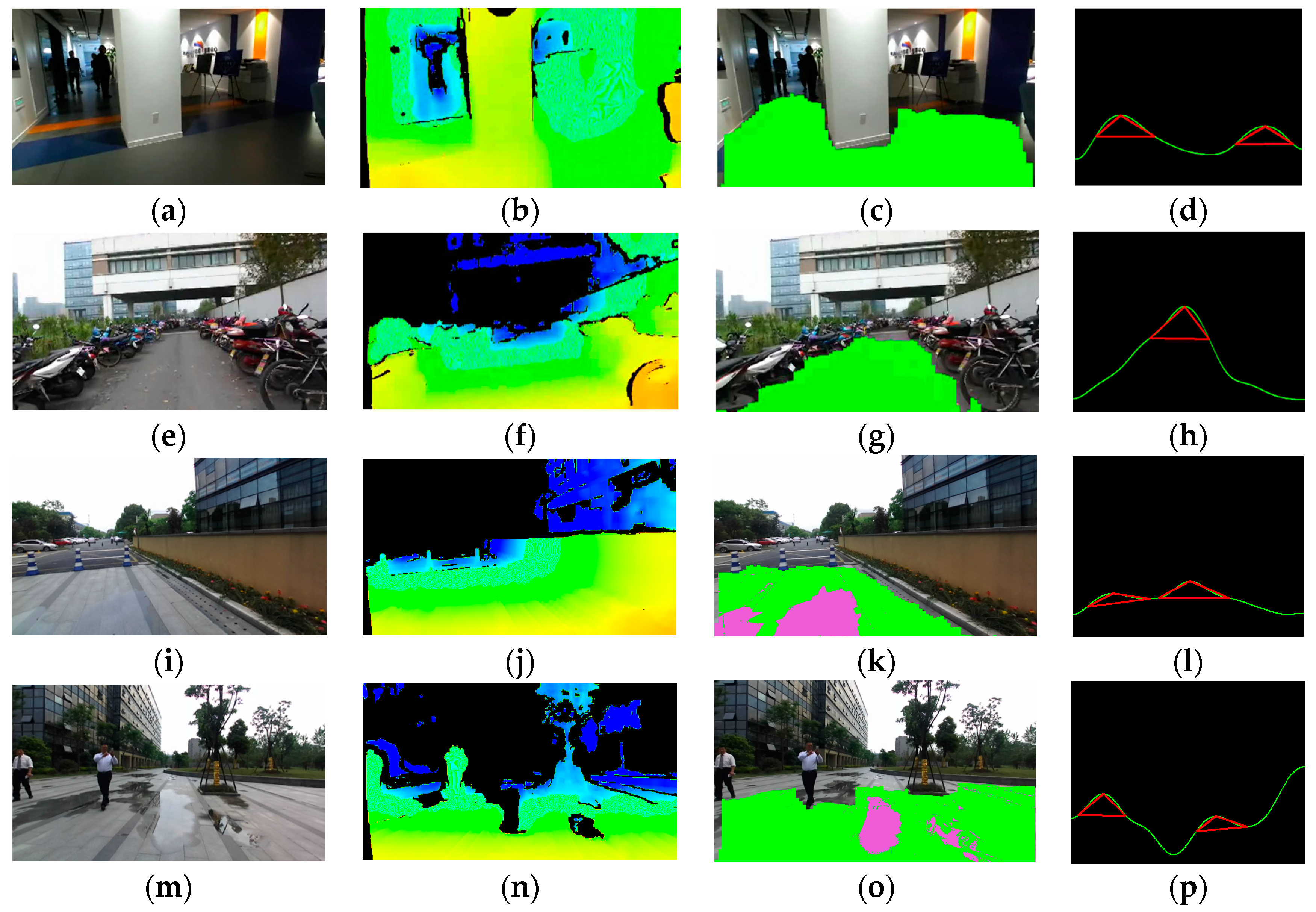
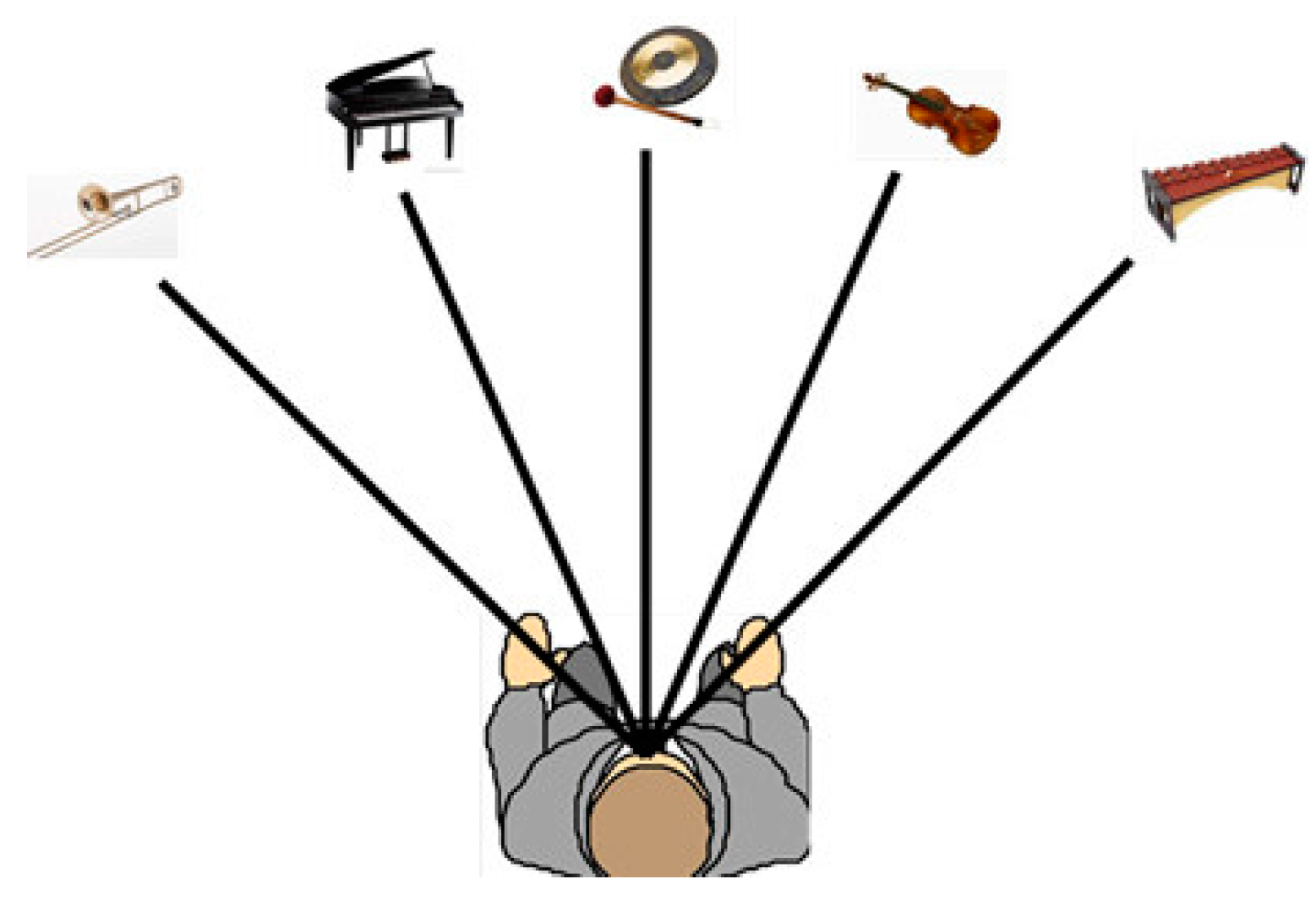
- Divide the farthest traversable line into five sections which correspond to the five different musical instruments. We only use five instruments to make sure that it is easy to understand and would not sound confusing after the familiarization period. Five instruments, including trumpet, piano, gong, violin and xylophone, produce sounds simultaneously.
- The horizontal field view of the pRGB-D sensor is 86.5°, so each musical instrument corresponds to the traversable line with a range of 17.3°.
- Each direction of traversable area and water hazard is represented by a musical instrument in the virtual 3D space.
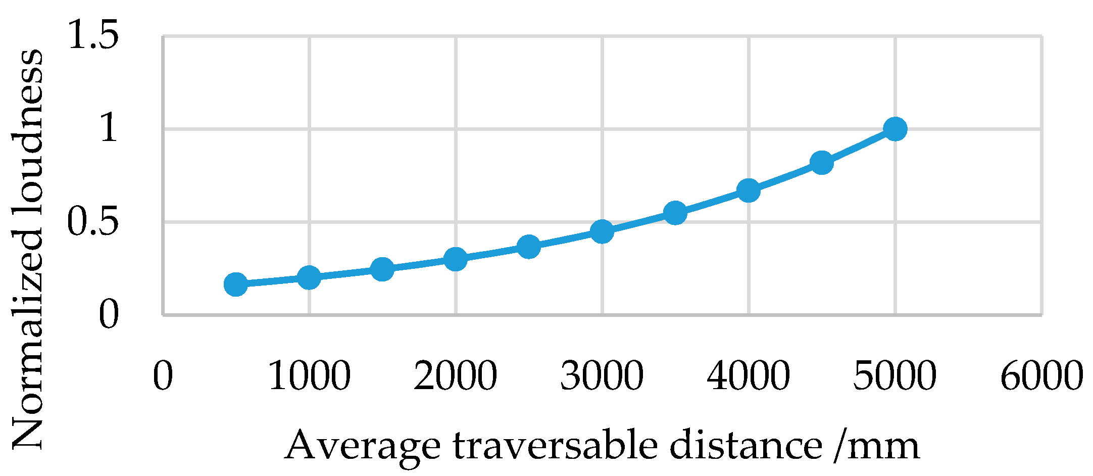
- For each musical instrument, the bigger the sum of height in the corresponding section of the traversable line, the louder the sound from the instrument. As the relationship shown in Figure 9, the instrument loudness increases exponentially with the average traversable distance in the corresponding section of the traversable line so as to guide or attract the user to navigate the traversable direction.
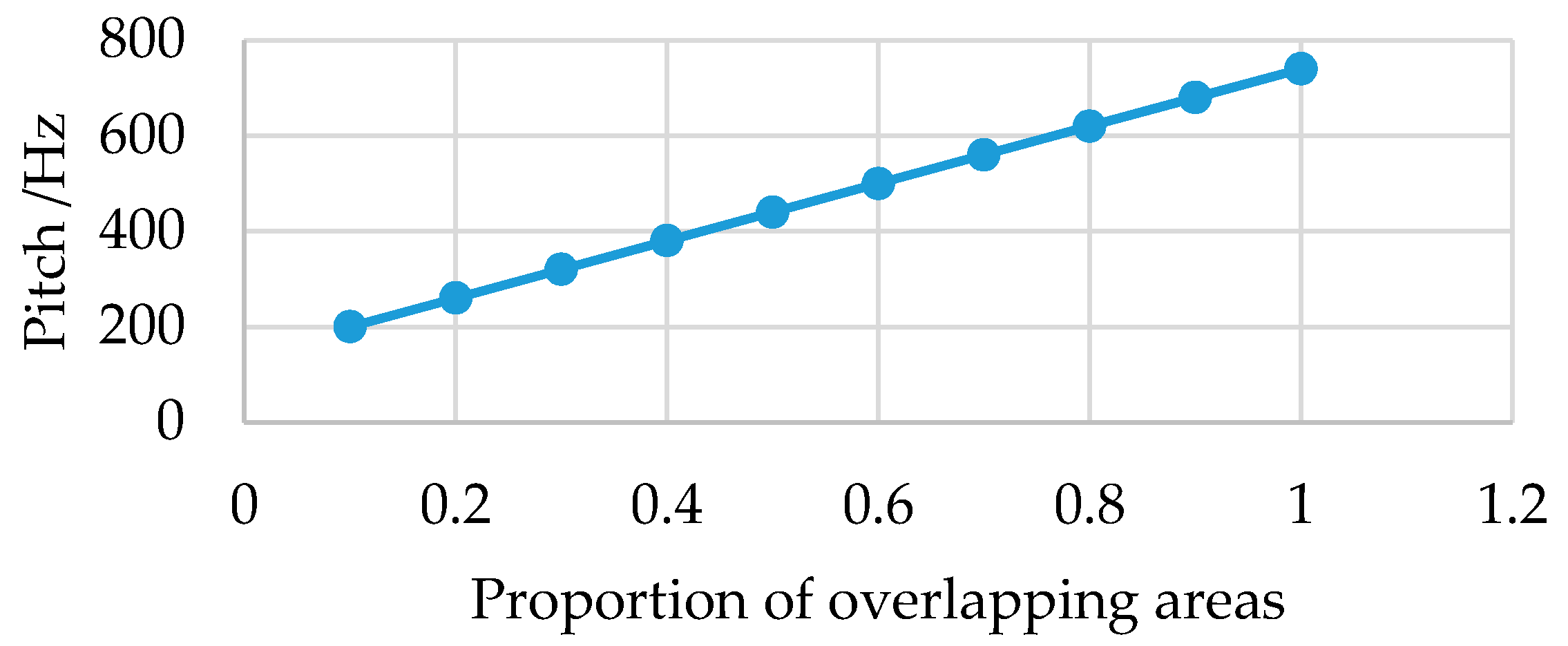
- For each musical instrument and the corresponding section, the bigger the areas that overlap with the red triangle sections which denote suggested directions to take on navigation, the higher the pitch of the instrument. As the relationship shown in Figure 10, the instrument pitch increases linearly with the proportion of the overlapping areas with the red triangle sections.
4. Experiments
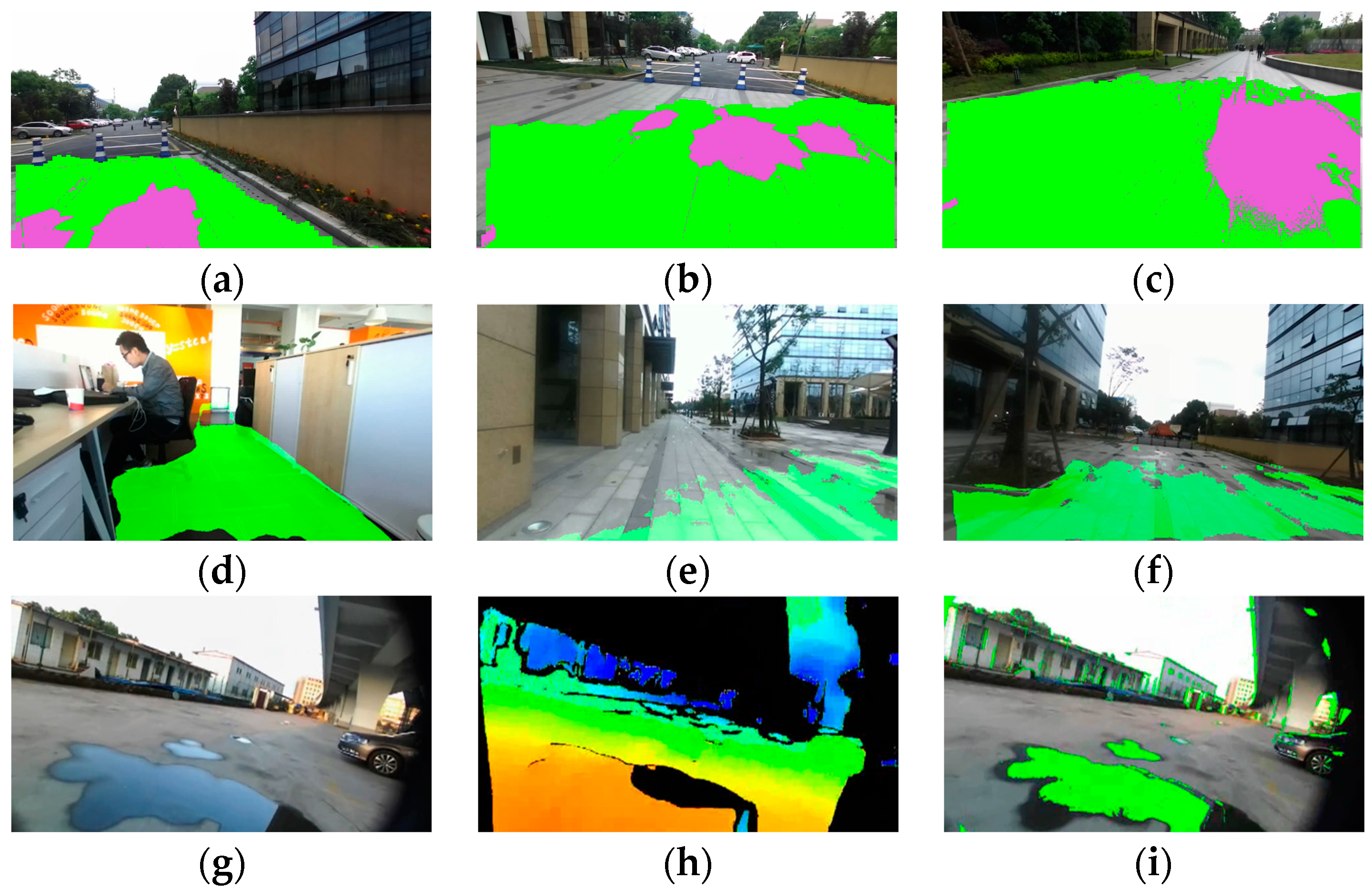
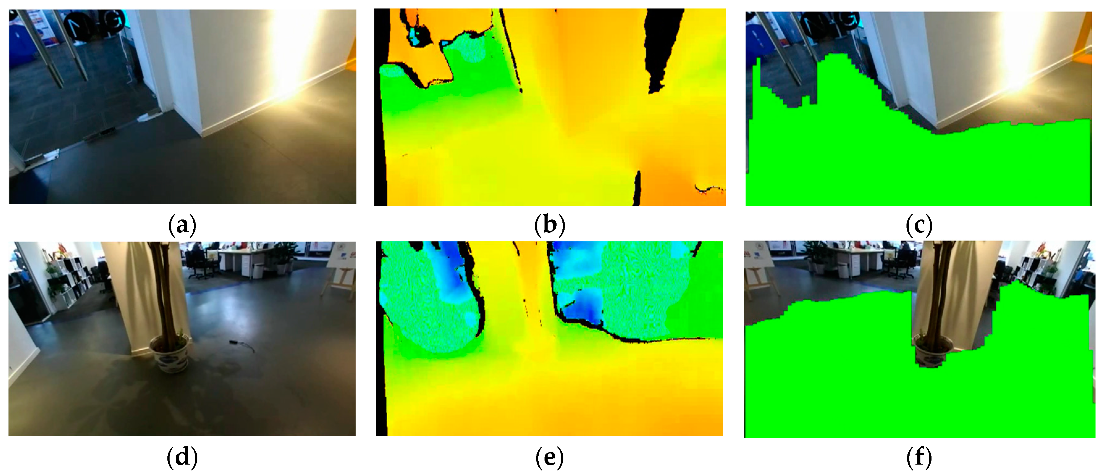
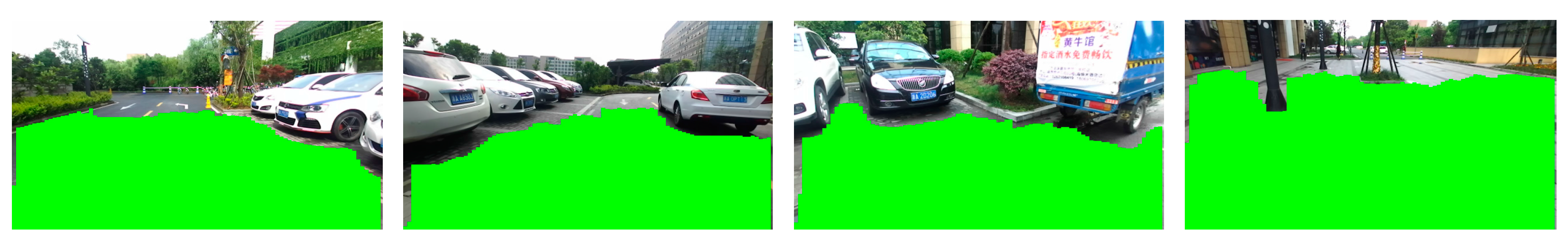
4.1. Indoor and Outdoor Detection Results
4.2. Comparison of Detection Results
4.3. Detection Limitations
4.4. User Study
5. Conclusions
Acknowledgments
Author Contributions
Conflicts of Interest
References
- World Health Organization. Visual Impairment and Blindness. Available online: http://www.who.int/mediacentre/factsheets/fs282/en/ (accessed on 6 June 2017).
- Zollner, M.; Huber, S.; Jetter, H.; Reiterer, H.C.; Reiterer, H. NAVI—A Proof-of-Concept of a Mobile Navigational Aid for Visually Impaired Based on the Microsoft Kinect. In Human—Computer Interaction—INTERACT 2011; Graham, P.C.N., Nunes, J.J.N., Winckler, P.M.M., Eds.; Springer: Berlin/Heidelberg, Germany, 2007; pp. 584–587. [Google Scholar]
- Takizawa, H.; Yamaguchi, S.; Aoyagi, M.; Ezaki, N.; Mizuno, S. Kinect cane: An assistive system for the visually impaired based on three-dimensional object recognition. Pers. Ubiquitous Comput. 2012, 19, 740–745. [Google Scholar]
- Filipe, V.; Fernandes, F.; Fernandes, H.; Sounsa, A.; Paredes, H.; Barroso, J. Assisted Guidance for the Blind Using the Kinect Device. In Proceedings of the 7th International Conference on Software Development and Technologies for Enhancing Accessibility and Fighting Info-exclusion, UTAD, Vila Real, Portugal, 1–3 December 2016; pp. 13–19. [Google Scholar]
- Park, C.H.; Howard, A.M. Real-time haptic rendering and haptic telepresence robotic system for the visually impaired. In Proceedings of the World Haptics Conference (WHC), Daejeon, Korea, 14–18 April 2013; pp. 229–234. [Google Scholar]
- Hicks, S.L.; Wilson, I.; Muhammed, L.; Worsfold, J.; Downes, S.M.; Kennard, C. A depth-based head-mounted visual display to aid navigation in partially sighted individuals. PLoS ONE 2013, 8, e67695. [Google Scholar] [CrossRef] [PubMed]
- Wang, Z.; Liu, H.; Wang, X.; Qian, Y. Segment and label indoor scene based on RGB-D for the visually impaired. In Proceedings of the International Conference on Multimedia Modeling, Dublin, Ireland, 6–10 January 2014; pp. 449–460. [Google Scholar]
- Aladren, A.; Lopez-Nicolas, G.; Puig, L.; Guerrero, J.J. Navigational assistance for the visually impaired using rgb-d sensor with range expansion. IEEE Syst. J. 2014, 99, 1–11. [Google Scholar]
- Hsieh, C.T.; Lai, W.M.; Yeh, C.H.; Huang, H.C. An Obstacle Detection System Using Depth Information and Region Growing for Blind. Res. Notes Inf. Sci. 2013, 465–470. [Google Scholar]
- Guerrero, J.J.; Pérez-Yus, A.; Gutiérrez-Gómez, D.; Rituerto, A.; López-Nicolás, G. Human navigation assistance with a RGB-D sensor. In Proceedings of the ACTAS V Congreso Internacional de Turismo para Todos: VI Congreso Internacional de Diseño, Redes de Investigación y Tecnología para todos DRT4ALL, Madrid, Spain, 23–24 September 2015; pp. 285–312. [Google Scholar]
- Cheng, R.; Wang, K.; Yang, K.; Zhao, X. A ground and obstacle detection algorithm for the visually impaired. In Proceedings of the IET International Conference on Biomedical Image and Signal Processing (ICBISP 2015), Beijing, China, 19 November 2015. [Google Scholar] [CrossRef]
- Yang, K.; Wang, K.; Cheng, R.; Zhu, X. A new approach of point cloud processing and scene segmentation for guiding the visually impaired. In Proceedings of the IET International Conference on Biomedical Image and Signal Processing (ICBISP 2015), Beijing, China, 19 November 2015. [Google Scholar] [CrossRef]
- Saputra, M.R.U.; Santosa, P.I. Obstacle Avoidance for Visually Impaired Using Auto-Adaptive Thresholding on Kinect’s Depth Image. In Proceedings of the 2014 IEEE 11th Intl Conf on Ubiquitous Intelligence and Computing and 2014 IEEE 11th Intl Conf on Autonomic and Trusted Computing and 2014 IEEE 14th International Conference on Scalable Computing and Communications and Its Associated Workshops, Bali, Indonesia, 9–12 December 2014. [Google Scholar] [CrossRef]
- Blessenohl, S.; Morrison, C.; Criminisi, A.; Shotton, J. Improving Indoor Mobility of the Visually Impaired with Depth-Based Spatial Sound. In Proceedings of the IEEE International Conference on Computer Vision Workshops, Santiago, Chile, 7–13 December 2015; pp. 26–34. [Google Scholar]
- Perez-Yus, A.; Lopez-Nicolas, G.; Guerrero, J.J. Detection and modelling of staircases using a wearable depth sensor. In Proceedings of the European Conference on Computer Vision, Zurich, Switzerland, 6–12 September 2014; pp. 449–463. [Google Scholar]
- Munoz, R.; Rong, X.; Tian, Y. Depth-aware indoor staircase detection and recognition for the visually impaired. In Proceedings of the 2016 IEEE International Conference on Multimedia & Expo Workshops (ICMEW), Seattle, WA, USA, 11–15 July 2016; pp. 1–6. [Google Scholar]
- Perez-Yuz, A.; Gutierrez-Gomez, D.; Lopez-Nicolas, G.; Guerrero, J.J. Stairs detection with odometry-aided traversal from a wearable RGB-D camera. Comput. Vis. Image Underst. 2017, 154, 192–205. [Google Scholar] [CrossRef]
- Wong, F.; Nagarajan, R.; Yaacob, S. Application of stereovision in a navigation aid for blind people. In Proceedings of the 2003 IEEE Joint Conference of the Four Information Communications and Signal Processing, and Fourth Pacific Rim Conference on Multimedia, Singapore, 15–18 December 2003; pp. 734–737. [Google Scholar]
- Johnson, L.A.; Higgins, C.M. A navigation aid for the blind using tactile-visual sensory substitution. In Proceedings of the 28th Annual International Conference of the IEEE on Engineering in Medicine and Biology Society (EMBS’06), New York, NY, USA, 31 August–3 September 2006; pp. 6289–6292. [Google Scholar]
- Rodriguez, A.; Bergasa, L.M.; Alcantarilla, P.F.; Yebes, J.; Cela, A. Obstacle avoidance system for assisting visually impaired people. In Proceedings of the IEEE Intelligent Vehicles Symposium Workshops, Madrid, Spain, 3–7 June 2012; p. 16. [Google Scholar]
- Martinez, J.M.S.; Ruiz, F.E. Stereo-based aerial obstacle detection for the visually impaired. In Proceedings of the Workshop on Computer Vision Applications for the Visually Impaired, Marseille, France, 18 October 2008. [Google Scholar]
- Pradeep, V.; Medioni, G.; Weiland, J. Robot vision for the visually impaired. In Proceedings of the 2010 IEEE Computer Society Conference on Computer Vision and Pattern Recognition Workshops (CVPRW), San Francisco, CA, USA, 13–18 June 2010; pp. 15–22. [Google Scholar]
- Brilhault, A.; Kammoun, S.; Gutierrez, O.; Truillet, P.; Jouffrais, C. Fusion of artificial vision and GPS to improve blind pedestrian positioning. In Proceedings of the 2011 4th IFIP International Conference on New Technologies, Mobility and Security (NTMS), Paris, France, 7–10 February 2011; pp. 1–5. [Google Scholar]
- Lee, Y.H.; Medioni, G. RGB-D camera based navigation for the visually impaired. In Proceedings of the RSS RGBD Advanced Reasoning with Depth Camera Wproorkshop, Los Angeles, CA, USA, 27 June 2011; pp. 1–5. [Google Scholar]
- Alcantarilla, P.F.; Yebes, J.J.; Almazan, J.; Bergasa, L.M. On Combining visual SLAM and dense scene flow to increase the robustness of localization and mapping in dynamic environments. In Proceedings of the 2012 IEEE International Conference on Robotics and Automation (ICRA), Saint Paul, MN, USA, 14–18 May 2012; pp. 1290–1297. [Google Scholar]
- Lin, K.W.; Lau, T.K.; Cheuk, C.M.; Liu, Y. A wearable stereo vision system for visually impaired. In Proceedings of the 2012 International Conference on Mechatronics and Automation (ICMA), Chengdu, China, 5–8 August 2012; pp. 1423–1428. [Google Scholar]
- Rodriguez, A.; Yebes, J.J.; Alcantarilla, P.F.; Bergasa, L.M.; Almazan, J.; Cele, A. Assisting the visually impaired: Obstacle detection and warning system by acoustic feedback. Sensors 2011, 12, 17476–17496. [Google Scholar] [CrossRef] [PubMed]
- Miksik, O.; Vineet, V.; Lidegaard, M.; Prasaath, R.; Nebner, M.; Golodetz, S.; Hicks, S.L.; Pérez, P.; Izadi, S.; Torr, P.H.S. The semantic paintbrush: Interactive 3d mapping and recognition in large outdoor spaces. In Proceedings of the 33rd Annual ACM Conference on Human Factors in Computing Systems, Seoul, Korea, 18–23 April 2015; pp. 3317–3326. [Google Scholar]
- Yang, K.; Wang, K.; Hu, W.; Bai, J. Expanding the Detection of Traversable Area with RealSense for the Visually Impaired. Sensors 2016, 16, 1954. [Google Scholar] [CrossRef] [PubMed]
- Huang, X.; Bai, J.; Wang, K.; Liu, Q.; Luo, Y.; Yang, K.; Zhang, X. Target enhanced 3D reconstruction based on polarization-coded structured light. Opt. Express 2017, 25, 1173–1184. [Google Scholar] [CrossRef] [PubMed]
- Ryan Fanello, S.; Rhemann, C.; Tankovich, V.; Kowdle, A.; Orts Escolano, S.; Kim, D.; Izadi, S. Hyperdepth: Learning depth from structured light without matching. In Proceedings of the IEEE Conference on Computer Vision and Patten Recognition, Seattle, WA, USA, 27–30 June 2016; pp. 5441–5450. [Google Scholar]
- Einecke, N.; Eggert, J. A two-stage correlation method for stereoscopic depth estimation. In Proceedings of the 2010 International Conference on Digital Image Computing: Techniques and Applications (DICTA), Sydney, Australia, 1–3 December 2010; pp. 227–234. [Google Scholar]
- Einecke, N.; Eggert, J. Block-matching stereo with relaxed fronto-parallel assumption. In Proceedings of the Intelligent Vehicles Symposium, Ypsilanti, MI, USA, 8–11 June 2014; pp. 700–705. [Google Scholar]
- Einecke, N.; Eggert, J. A multi-block matching approach for stereo. In Proceedings of the 2015 IEEE Intelligent Vehicles Symposium (IV), Seoul, Korea, 28 June–1 July 2015; pp. 585–592. [Google Scholar]
- Hirschmuller, H. Stereo processing by semiglobal matching and mutual information. IEEE Trans. Pattern Anal. Mach. Intell. 2008, 30, 328–341. [Google Scholar] [CrossRef] [PubMed]
- Xie, Y.; Zeng, S.; Chen, L. A Novel Disparity Refinement Method Based on Semi-Global Matching Algorithm. In Proceedings of the 2014 IEEE International Conference on Data Mining Workshop (ICDMW), Shenzhen, China, 14 December 2014; pp. 1135–1142. [Google Scholar]
- Hernandez-Juarez, D.; Chacon, A.; Espinosa, A.; Vazquez, D.; Moure, J.C.; Lopez, A.M. Embedded real-time stereo-estimation via Semi-Global Matching on the GPU. Procedia Comput. Sci. 2016, 80, 143–153. [Google Scholar] [CrossRef]
- Keselman, L.; Woodfill, J.I.; Grunnet-Jepsen, A.; Bhowmik, A. Intel RealSense Stereoscopic Depth Cameras. arXiv 2017, arXiv:1705.05548. [Google Scholar]
- Konolige, K. Projected texture stereo. In Proceedings of the 2010 IEEE International Conference on Robotics and Automation(ICRA), Anchorage, AK, USA, 4–8 May 2010; pp. 148–155. [Google Scholar]
- Stereolabs. Available online: Http://www.stereolabs.com (accessed on 6 June 2017).
- Dakopoulos, D.; Bourbakis, N.G. Wearable obstacle avoidance electronic travel aids for blind: A survey. IEEE Trans. Syst. Man Cybern. Part C Appl. Rev. 2015, 40, 25–35. [Google Scholar] [CrossRef]
- Wang, T.; Bu, L.; Huang, Z. A new method for obstacle detection based on Kinect depth image. In Proceedings of the 2015 Chinese Automation Congress (CAC), Wuhan, China, 27–29 November 2015; pp. 537–541. [Google Scholar]
- Badino, H.; Franke, U.; Pfeiffer, D. The stixel world-a compact medium level representation of the 3D-world. In Proceedings of the 31st DAGM Symposium, Jena, Germany, 9–11 September 2009; pp. 51–60. [Google Scholar]
- Wedel, A.; Franke, U.; Badino, H.; Cremers, D. B-spline modelling of road surfaces for freespace estimation. In Proceedings of the 2008 IEEE Intelligent Vehicles Symposium, Eindhoven, The Netherlands, 4–6 June 2008; pp. 808–833. [Google Scholar]
- Elleuch, J.F.; Bellaaj, M.; Sellami, D.; Kallel, I.K. Travesable area segmentation approach at indoor environment for visually impaired people. In Proceedings of the 13th International Conference on Advances in Mobile Computing and Multimedia, Brussels, Belgium, 11–13 December 2015; pp. 48–53. [Google Scholar]
- Frikha, J.; Sellami, D.; Kallel, I.K. Indoor/outdoor navigation system based on possibilistic traversable area segmentation for visually impaired people. ELCVIA Electron. Lett. Comput. Vis. Imag. Anal. 2016, 15, 60–76. [Google Scholar] [CrossRef]
- Koester, D.; Schauerte, B.; Stiefelhagen, R. Accessible section detection for visual guidance. In Proceedings of the IEEE International Conference on Multimedia and Expo Workshops, San Jose, CA, USA, 15–19 July 2013; pp. 1–6. [Google Scholar]
- Bellone, M.; Messina, A.; Reina, G. A new approach for terrain analysis in mobile robot applications. In Proceedings of the IEEE International Conference on Mechatronics, Wollongong, Australia, 9–12 July 2013; pp. 225–230. [Google Scholar]
- Ni, D.; Song, A.; Tian, L.; Xu, X.; Chen, D. A walking assistant robotic system for the visually impaired based on computer vision and tactile perception. Int. J. Soc. Robot. 2015, 7, 617–628. [Google Scholar] [CrossRef]
- Cui, J.; Guo, Y.; Zhang, H.; Qian, K.; Bao, J.; Song, A. Support Vector Machine Based Robotic Traversability Prediction with Vision Features. Int. J. Comput. Intell. Syst. 2013, 6, 596–608. [Google Scholar] [CrossRef]
- Rankin, A.L.; Matthies, L.H.; Huertas, A. Daytime water detection by fusing multiple cues for autonomous off-road navigation. In Transformational Science and Technology for the Current and Future Force; Wei, T.K., Ed.; World Scientific Publishing Co. Pte. Ltd.: Singapore, 2006; pp. 177–183. [Google Scholar]
- Yao, T.; Xiang, Z.; Liu, J.; Xu, D. Multi-feature fusion based outdoor water hazards detection. In Proceedings of the 2007 IEEE International Conference on Mechatronics and Automation (ICMA), Harbin, China, 5–8 August 2007; pp. 652–656. [Google Scholar]
- Xie, B.; Pan, H.; Xiang, Z.; Liu, J. Polarization-based water hazards detection for autonomous off-road navigation. In Proceedings of the International Conference on Mechatronics and Automation (ICMA), Harbin, China, 5–8 August 2007; pp. 1666–1670. [Google Scholar]
- Yao, T.Z.; Xiang, Z.Y.; Liu, J.L. Robust water hazard detection for autonomous off-road navigation. J. Zhejiang Univ. 2009, 10, 786–793. [Google Scholar] [CrossRef]
- Rankin, A.L.; Matthies, L.H.; Bellutta, P. Daytime water detection based on sky reflections. In Proceedings of the 2011 IEEE International Conference on Robotics and Automation (ICRA), Shanghai, China, 9–13 May 2011; pp. 5329–5336. [Google Scholar]
- Shao, H.; Zhang, Z.; Li, K. Research on water hazard detection based on line structured light sensor for long-distance all day. In Proceedings of the 2015 IEEE International Conference on Mechatronics and Automation (ICMA), Beijing, China, 2–5 August 2015; pp. 1785–1789. [Google Scholar]
- Kim, J.; Baek, J.; Choi, H.; Kim, E. Wet area and puddle detection for Advanced Driver Assistance Systems (ADAS) using a stereo camera. Int. J. Control Autom. Syst. 2016, 14, 263. [Google Scholar] [CrossRef]
- Nguyen, C.V.; Milford, M.; Mahony, R. 3D tracking of water hazards with polarized stereo cameras. arXiv 2017, arXiv:1701.04175. [Google Scholar]
- InvenSense MPU-6050. Available online: https://playground.arduino.cc/Main/MPU-6050 (accessed on 6 June 2017).
- Badino, H.; Franke, U.; Mester, R. Free space computation using stochastic occupancy grids and dynamic programming. In Proceedings of the 2007 ICCV Workshop on Dynamical Vision, Rio de Janeiro, Brazil, 20 October 2007; Available online: http://www.lelaps.de/papers/badino_wdv2007.pdf (accessed on 12 August 2017).
- Kaiwei Wang Team. Available online: wangkaiwei.org (accessed on 6 June 2017).
- Kumar, S.; Karthik, M.S.; Krishna, K.M. Markov Random Field based small obstacle discovery over images. In Proceedings of the 2014 IEEE International Conference on Robotics and Automation (ICRA), Hong Kong, China, 31 May–7 June 2014; pp. 494–500. [Google Scholar]
- AMAP. Available online: http://ditu.amap.com/ (accessed on 6 June 2017).


| Approaches | % | % | % |
|---|---|---|---|
| Proposed approach without water area detection | 94.4% | N/A | 60.6% |
| Proposed approach with water area detection | 94.4% | 89.2% | 7.3% |
| RANSAC plus filtering techniques [27] | 79.6% | N/A | 41.5% |
| RANSAC plus expanding techniques [29] | 93.8% | N/A | 65.2% |
| 3D tracking of water areas [58] | N/A | 86.5% | N/A |
| Transferred Detection Result | Average Time to Complete | Average Number of Collisions into Obstacles | Average Number of Times Stepping in Water Areas |
|---|---|---|---|
| traversable area detection | 24 min 32 s | 3.0 | 30.6 |
| traversable area and water hazard detection | 26 min 11 s | 2.6 | 2.8 |
| User | Easy to Wear? | Could You Use the Stereo Sound Feedback to Find Traversable Directions? |
|---|---|---|
| User 1 | Yes | Yes |
| User 2 | Yes | Yes |
| User 3 | No | Yes |
| User 4 | Yes | Yes |
| User 5 | Yes | Yes |
| User 6 | Yes | Yes |
| User 7 | No | Yes |
| User 8 | No | Yes |
| User 9 | Yes | Yes |
| User 10 | Yes | Yes |
© 2017 by the authors. Licensee MDPI, Basel, Switzerland. This article is an open access article distributed under the terms and conditions of the Creative Commons Attribution (CC BY) license (http://creativecommons.org/licenses/by/4.0/).
Share and Cite
Yang, K.; Wang, K.; Cheng, R.; Hu, W.; Huang, X.; Bai, J. Detecting Traversable Area and Water Hazards for the Visually Impaired with a pRGB-D Sensor. Sensors 2017, 17, 1890. https://doi.org/10.3390/s17081890
Yang K, Wang K, Cheng R, Hu W, Huang X, Bai J. Detecting Traversable Area and Water Hazards for the Visually Impaired with a pRGB-D Sensor. Sensors. 2017; 17(8):1890. https://doi.org/10.3390/s17081890
Chicago/Turabian StyleYang, Kailun, Kaiwei Wang, Ruiqi Cheng, Weijian Hu, Xiao Huang, and Jian Bai. 2017. "Detecting Traversable Area and Water Hazards for the Visually Impaired with a pRGB-D Sensor" Sensors 17, no. 8: 1890. https://doi.org/10.3390/s17081890
APA StyleYang, K., Wang, K., Cheng, R., Hu, W., Huang, X., & Bai, J. (2017). Detecting Traversable Area and Water Hazards for the Visually Impaired with a pRGB-D Sensor. Sensors, 17(8), 1890. https://doi.org/10.3390/s17081890