1. Introduction
With the rapid advance of the micro- and nanotechnologies in micro/nano-electro-mechanical systems (MEMS/NEMS), more and more micro- and nanomechanical resonators have been developed, which are of interest to both the scientific community and engineering fields due to their significant advantages such as small size, compactness, high sensitivity, high resolution, low power consumption and low cost, and high quality factor [
1,
2,
3,
4,
5]. Due to their small sizes, micro- and nanomechanical resonators can oscillate at very high resonant frequencies, which provides them with a remarkable ability to perform both sensing and detection in advanced technological applications, including ultrasensitive mass and force sensing, ultralow-power radio frequency (RF) signal generation and timing, chemical and biological sensing, cooling, environmental control, and quantum measurement [
6,
7,
8,
9,
10,
11,
12]. However, there still exist fundamental and technological challenges to tunable micro- and nanomechanical resonators.
In general, different techniques for designing the micro- and nanomechanical resonators can be categorized into both vibration-based methods and wave propagation-based methods [
13]. The fundamental characteristics of mechanical resonators are determined by the resonant frequency and quality factor (energy dissipation). As one of the important attributions to resonating MEMS/NEMS devices, resonant frequency often determines the sensitivity and accuracy of the system. Various micro- and nanomechanical resonator applications, such as high resolution sensors, RF oscillators and filters, can be benefit from the tuning capability of resonant frequency or operation range, which allows fabrication of multi-functional components for multi-band filtering, has low power temperature compensation targeted for timing reference and RF synthesizing applications [
14,
15,
16,
17,
18,
19,
20,
21,
22,
23,
24,
25,
26,
27,
28]. The most desirable function is the tunability of the resonant frequency, which can be used to compensate for the resonant frequency shift in resonators due to the changes in temperature, pressure, or atmosphere composition [
14]. An interesting application frequency tuning is the ability to controllably couple the out-of-plane and in-plane vibration modes as the frequencies of the two modes are tuned closer to each other [
15]. It can be used to optimize frequency and nonlinearity tuning and to increase the pull-in threshold for specific applications of small and sensitive devices as linear sensors. Frequency tuning on short timescales [
16] can be necessary for mechanical signal processing which requires signal tracking, frequency hopping,
etc. Moreover, frequency tuning can be applied when the structure dimensions of the resonators changes due to the fabrication process [
16], can be useful in controlling frequency instability and deterministic switching between bistable states [
17], and can realize controllable sensitivity [
18]. Therefore, the ability to tune the resonant frequency of a micro- and nanomechanical resonator is crucial for potential applications. The fundamental understanding of the frequency tuning mechanisms becomes important for the future design and optimization of micro- and nanomechanical resonators in the very-high frequency (VHF), ultra-high frequency (UHF) ranges.
The resonant frequency of micro- and nanomechanical resonators depend upon many factors, including geometry, structural material properties, stress, external loading, and surface topography. Many methods have been proposed to guarantee frequency tuning throughout the lifetime of micro- and nanomechannical resonators, and overcomes the relative drawbacks arouse from the nonlinear effect, environmental effect and fabrication related effects such as processing temperatures, fabrication tolerances, structural non-idealities and asymmetries, residual stress as well as design errors and defects which can cause resonant frequency shift [
19,
20,
21,
22]. Therefore, it is important to develop tuning methods which depend on the change of the stiffness or mass of the mechanical resonators. Inducing stresses in the resonator can change its effective stiffness and the resonant frequency [
14]. Since micro- and nanomechanical resonators are characterized by a large surface-to-volume ratio, it is demonstrated that the surface phenomena plays a significant role on not only the resonance behavior but also the sensing or actuating performance of the devices [
23,
24]. In addition, micro- and nanomechanical resonators have widely implemented in various fluidic environments, as a result, the viscous fluids lead to the shift of resonant frequency in the resonators and the fluid-structure interaction causes the challenge to perform measurement in viscous fluids [
25,
26].
Various geometry structures like cantilever and bridge beams, and plates are the most typical micro- and nanomechanical resonators. Recent advance of fabrication technologies leads to the increasing complexity of resonating devices which generate challenges to potential resonator applications [
27]. Micro- and nanomechanical resonators using the structures and materials such as tuning electrode [
28], tuning fork [
29], suspended channel structure [
30], carbon nanotubes [
31], nanowires [
32], graphene sheets [
33] and bulk micromachined structures [
34], as well as the smallest man-made self-assembled molecular structure [
35] provide the promise of new applications and allow us to explore fundamental properties at the micro- and nanoscales. It is of great interest to tune and control their resonant frequencies reversibly.
Frequency tuning methods can be usually divided into two major categories: active and passive methods [
36]. Many researchers have extensively developed various methodologies to address the changes by correcting the resonant frequency using tuning procedures. Active tuning is defined as a tuning mechanism that is continuously applied even if the resonant frequency closely matches the excitation vibration frequency [
37]. Real time tuning makes these methods very attractive and some active methods, including electrothermal [
14,
19], electrostatic [
38,
39,
40], magnetomotive [
41], piezoelectrical [
42,
43], dielectric [
44], photothermal [
45], and modal coupling [
46,
47], as well as the tension-induced tuning mechanisms, have been developed and reported. In contrast, passive tuning method often operates periodically and only consumes power during the tuning operation [
37]. The manufacturing variations due to fabrication processes may cause discrepancies in designed specifications, which should be needed to compensate using the post-fabrication tuning processes [
48]. However, these methods are unable to implement real time frequency tuning for mechanical resonators throughout their lift times. Furthermore, zero on-chip energy consumption makes passive methods favorable for low power applications [
36].
During the past several years, some extensive and critical reviews on micro- and nanomechanical resonators and comprehensive analyses of their wide rage for MEMS/NEMS applications have reported [
49,
50,
51], such as the recent reviews on carbon nanotube and graphene-based nanomechanical resonators [
2,
13,
52,
53,
54], microcantilever-based resonator applications and sensing principles [
55], nanomechanical resonators and their applications in biological/chemical detection [
56] and visualization of material structure [
57], nonlinear dynamics and its applications in micro-and nanomechanical resonators [
58], MEMS-based oscillators for frequency reference applications [
59], micromechanical resonators applied in vibration energy harvesters [
60], cantilever-like micromechanical resonators for recent sensor applications [
61], nanomechanical resonators for all-optical mass sensing [
11], dissipation in nanomechanical resonator structures [
62], some fundamental and nonfundamental noise processes limited the performance of nanomechanical resonators [
63], and an outlook of how state-of-the art mechanical resonators can be improved to study quantum mechanics [
64]. The current review focuses on the methodologies of frequency tuning for micro- and nanomechanical resonators. The purpose of this review is to present not only the current state-of-the-art in the development of frequency tuning methods for micro- and nanomechanical resonator applications, but also the resonant frequency shift due to the major influencing factors that have enabled fundamental insights into the frequency tuning principles and mechanisms as well as the some novel tuning structures and tunable resonators.
This review is organized as follows: In
Section 2, we present the theoretical description of the resonance behavior in the flexural and torsional modes of vibration of the beam-based mechanical resonators.
Section 3 provides the brief overview of the frequency tuning principle for the resonators, in which the flexural and torsional operation modes of motion are described via a basic mechanical model. Except for the typical beam/plate-based micro- and nanomechanical resonators, an overview of some novel tuning structures such as tuning electrodes, tuning fork and suspended channel, and newly tunable resonators made from graphene are reviewed and discussed in
Section 4. Performance issues such as sensitivity, stability and resolution are also addressed.
Section 5 focuses on the major influencing factors, such as large-amplitude effect, surface stress effect and fluid effect, which affect the resonant frequency shift in resonators, and briefly review the efforts implemented to predict, control and apply the resonant frequency shift for overcoming challenges and potential applications. The active and passive tuning mechanisms, methods and techniques, and extending applications are reviewed in detail and discussed in
Section 6 and
Section 7. A perspective on future challenges and conclusion remarks are concluded in
Section 8.
6. Active Frequency Tuning Method
Although substantial development and progress in the transduction techniques [
264], an efficient, integrated, and customizable strategy for frequency tuning of micro- and nanomechanical resonators has remained elusive [
42]. In order to achieve resonance in the mechanical structure of a MEMS/NEMS resonator, the device must be actuated by an actuator and set to resonate by varying the excitation frequency. Efficient actuation is crucial to obtaining optimal performance. A variety of tuning techniques, including the electrothermal, electrostatic, and magnetic, piezoelectric, optothermal and dielectric excitation methods, have been developed for actuating resonance. The general excitation mechanisms can be divided into local on-chip schemes [
51] and approaches depending on external excitations [
34]. The former arises from the voltage-induced forces through different types of sources such as electrothermal [
265], capacitive, magnetomotive [
41], internal piezoelectrical [
42,
43], or static dipole-based dielectric [
44]. The latter implement external excitation such as photothermal [
45] or inertia-based piezo-actuated schemes [
42].
Table 7 provides the comparison of several actuation mechanisms which are widely used for frequency tuning of resonators [
115]. We review these different active mechanisms as well as nonlinear mode coupling that have been developed for frequency tuning of the micro- and nanomechanical resonators.
Table 7.
Comparison of several actuation mechanisms applied for micro- and nanomechanical resonators.
Table 7.
Comparison of several actuation mechanisms applied for micro- and nanomechanical resonators.
| Actuation Type | Fabrication Process | Power Consumption | Applied Voltage | Current | Nonlinear Effect |
|---|
| Electrothermal | Simple | High | Low | High | Medium |
| Electrostatic | Simple | Low | High | Low | High |
| Piezoelectric | Complex | Low | Medium | Low | High |
| Magnetomotive | Simple | Medium | Low | Medium | High |
| Dielectric | Medium | High | High | - | High |
| Photothermal | Complex | Medium | - | - | High |
6.1. Electrothermal Tuning Mechanism
The resonant frequency of a resonator can be shifted by inducing an expansion or contraction of the structure electro-thermally [
85]. The advantages of electro-thermal actuation include simplified fabrication and relatively low operating voltages [
266]. Several electrothermal tuning techniques were developed for frequency tuning of microresonators such as resistive heating to introduce thermal strains [
19] and localized thermal induced stressing [
14]. However, these techniques generally suffer from high power dissipation.
When the electrical current is applied to the resonator, it causes resistive heating and the electro-thermal model can be given by [
267]:
where
is the thermal conductivity,
denotes the net heat loss rate to the substrate per unit length,
is the cross-sectional area,
is the room temperature, and
refers to the Joule heating rate per unit length, in which
is the electrical current, and
is the resistance.
Both on the relationship of stress and strain, the thermal stress
for the resonators under Joule heating can be expressed as:
where
is thermal expansion coefficients (TEC) and
is the derivative of temperature. For the case of nanotube resonators, Pop
et al. [
267] deduced the temperature profiles
, where
is the characteristic thermal healing length. Mei and Li [
18] recently presented the temperature profile a
, where
. If the material has a uniform change
, the change in length
yields
, where
is the initial length of the material. When the expansion of the material is affected by the interaction to another material, the thermal stress
can be simplified as
[
85]. Under the effect of thermal stress, the resonant frequency can be given by [
16]:
where
is the tensile stress, and it is the sum of the initial tensile stress
from the film deposition process and the thermal stress
from heating of the structure. Jun
et al. [
16] provided a single expression for the thermal tuning of a beam as follows:
where
is the initial measured frequency under the initial tensile stress and
,
,
and
are the effective thermal expansion coefficient, thermal conductivity, and electrical heat production, respectively.
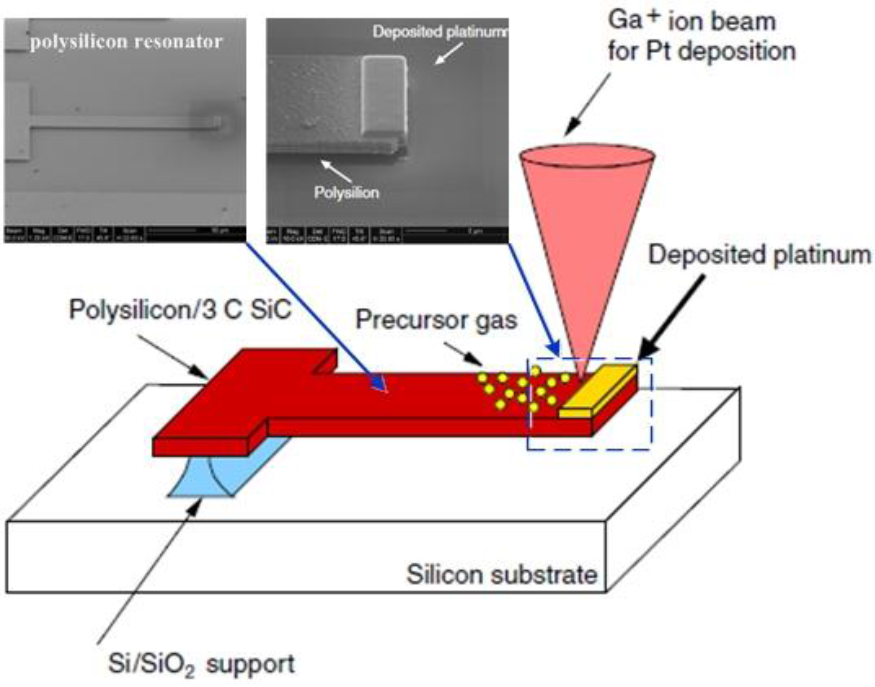
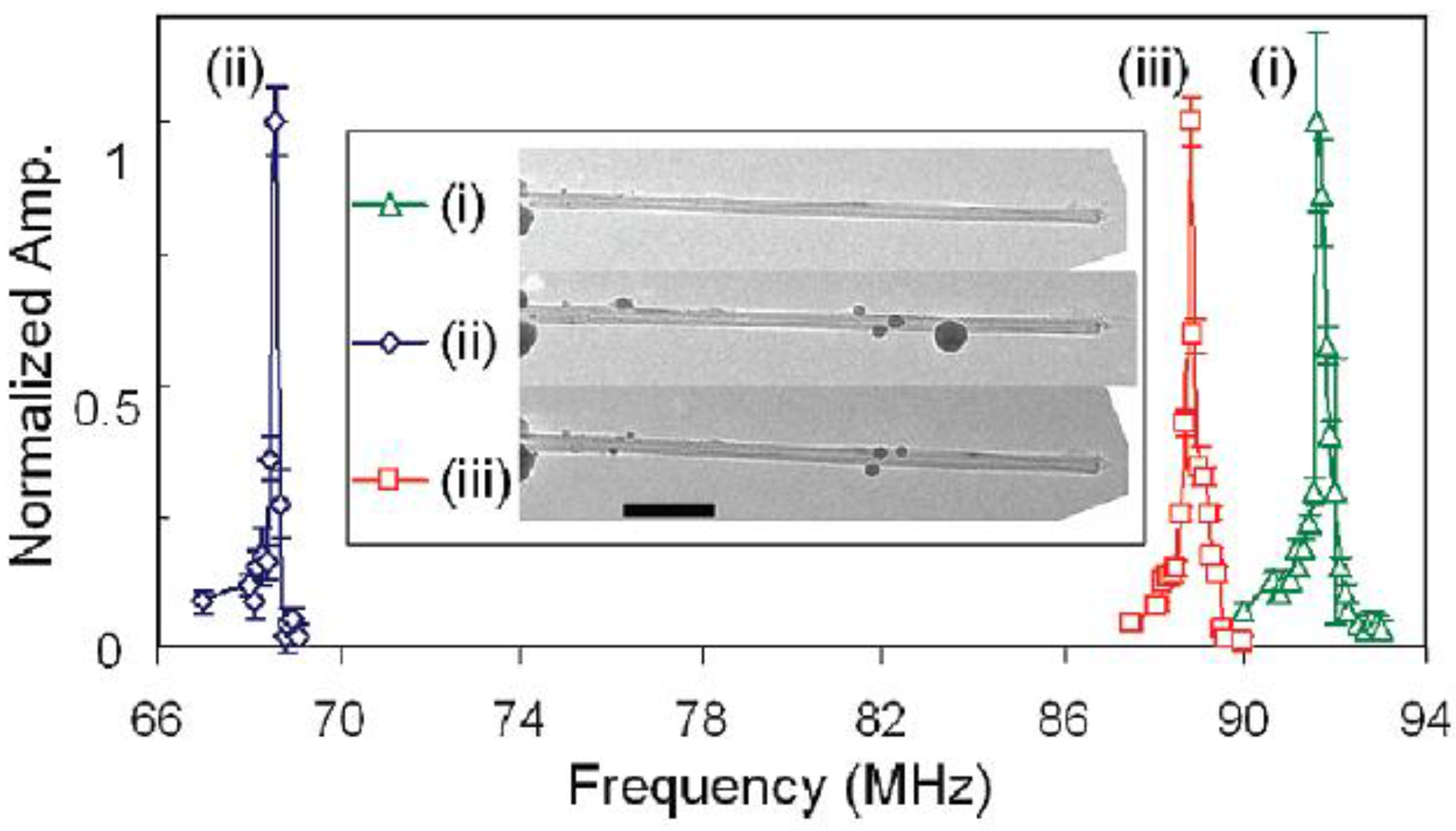
As shown in
Figure 19, Jun
et al. [
268,
269] used this effective electrothermal tuning method, which was widely applied to tune frequency of MEMS devices [
14,
19], for composite nanomechanical resonators with ultrathin 3C-SiC films and 30–195 nm of aluminium [
1,
27]. A DC tuning voltage up to 100 mV was applied in parallel with the RF drive for the electrothermal tuning [
270]. The direct current heats the beam, and thus changes the stress and decreases the resonant frequency, which was tuned by 10% with Joule heating of DC current [
268]. Upon heating, the quality factor decreases by up to ~8% [
16]. The resonant frequency shifts about 6.5% at 31 kHz using electro-thermal stiffness change [
19]. A tuning range of up to 1.1% from the frequency of 39.2 kHz with 54 mW power was reported in [
271]. The SNR level decreases almost linearly with the increase of tuning power [
269]. In addition, the effect of frequency tuning by magnetic field was controlled by interplay between stress- and shape-induced anisotropy energies [
272].
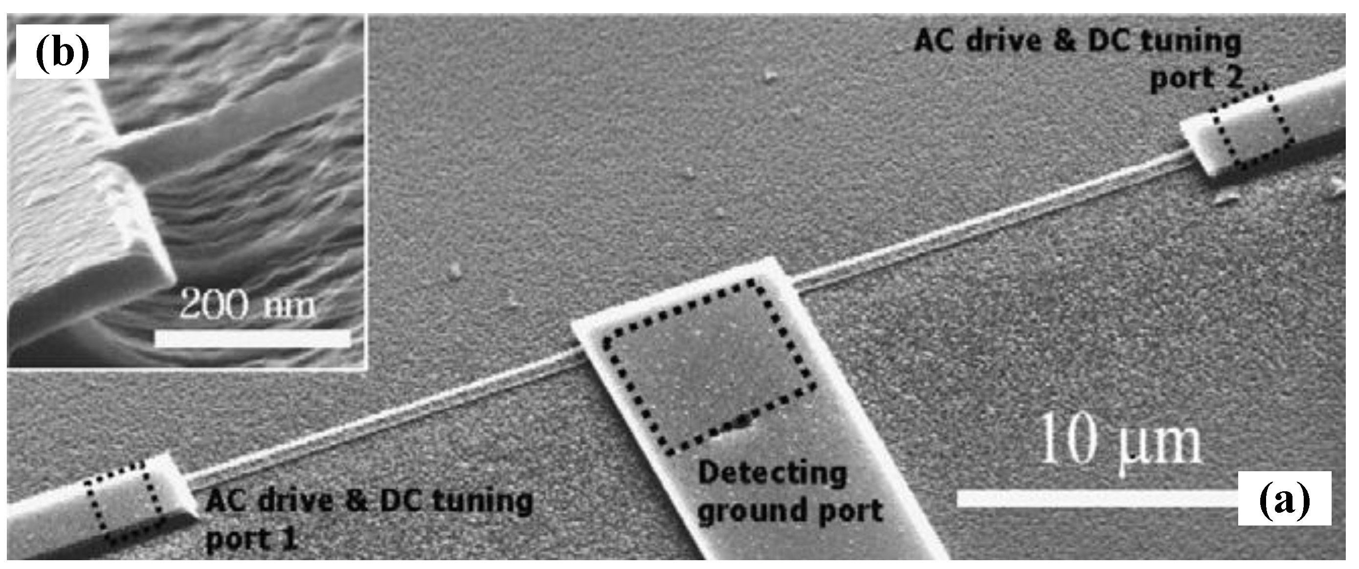
Figure 19.
(
a) SEM of a completed nano-mechanical resonator [
16]. The nanobeams with two AC driving and DC tuning ports and a detection port; (
b) Close-up view of the suspended structure. Reused with permission from [
16], Copyright 2006, IOP Publishing.
Figure 19.
(
a) SEM of a completed nano-mechanical resonator [
16]. The nanobeams with two AC driving and DC tuning ports and a detection port; (
b) Close-up view of the suspended structure. Reused with permission from [
16], Copyright 2006, IOP Publishing.
The resonant frequency of the resonator with the thermal axial load
can be expressed as [
270,
273]:
The tension
in the resonator beam after the dc heating changes from
to:
where
, in which
is the specific heat conductivity,
is the mass of the resonator, and
is the resistance. It notes that electrothermal heating is one of radio frequency tuning method in nanomechanical resonators with magnetomotive transduction and can modify the dynamic range of the resonators [
273,
274,
275,
276].
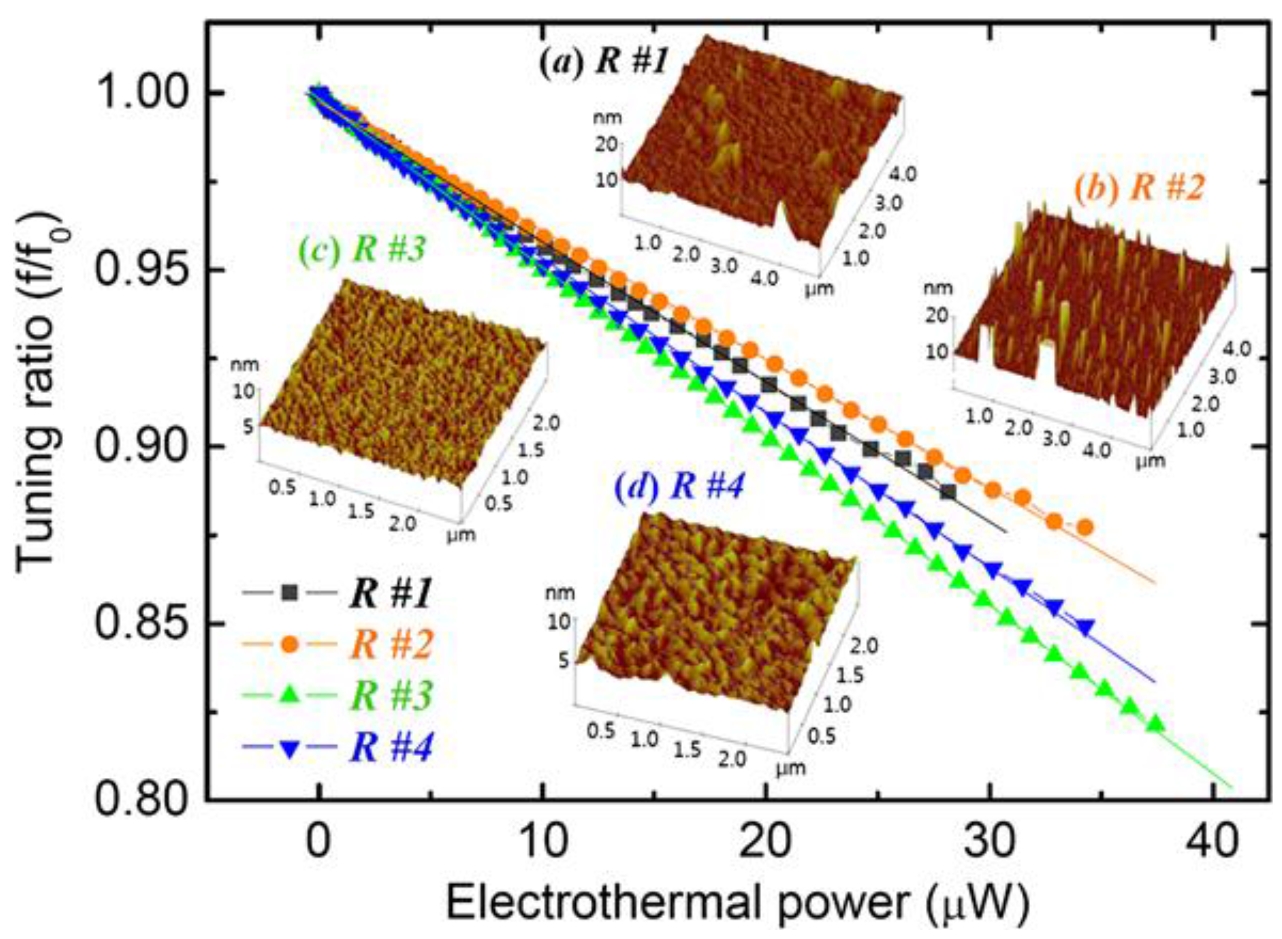
As illustrated in
Figure 20, tuning power and surface roughness have a significant role on the frequency tuning properties. On one hand, when the tuning power was supplied, the resonant frequency of the resonator was tuned downward due to the Joule heating [
275]. On the other hand, the surface roughness is an important parameter influencing the resonant frequency and tuning performance. The surface roughness makes the loss of resonating performance more complicated to predict. It demonstrated that the dissipation prevails more on a rougher surface due to the effects of electron scattering, energy loss, and unequal or non-uniform electrothermal heating [
270,
275].
Figure 20.
Frequency tuning performance as a function of surface roughness of the nanobeam resonator [
275]. The average roughness of the samples (
a) R#1: 11.2nm, (
b) R#2: 28.8 nm, (
c) R#3: 0.9nm, and (
d) R#4: 2.4nm, observed in AFM image of surface morphology. Reused with permission from [
275].
Localized heating [
277,
278] was demonstrated to be one effective method for frequency tuning of micromechanical resonators. The possibility of programming multiple eigenfrequency states of the microresonator with localized Joule effect was also reported [
279]. More recently, frequency self-tuning of CNT resonator using joule heating mechanism was demonstrated to improve the mass detection sensitivity from 1.783 MHz/zg to 5.013 MHz/zg [
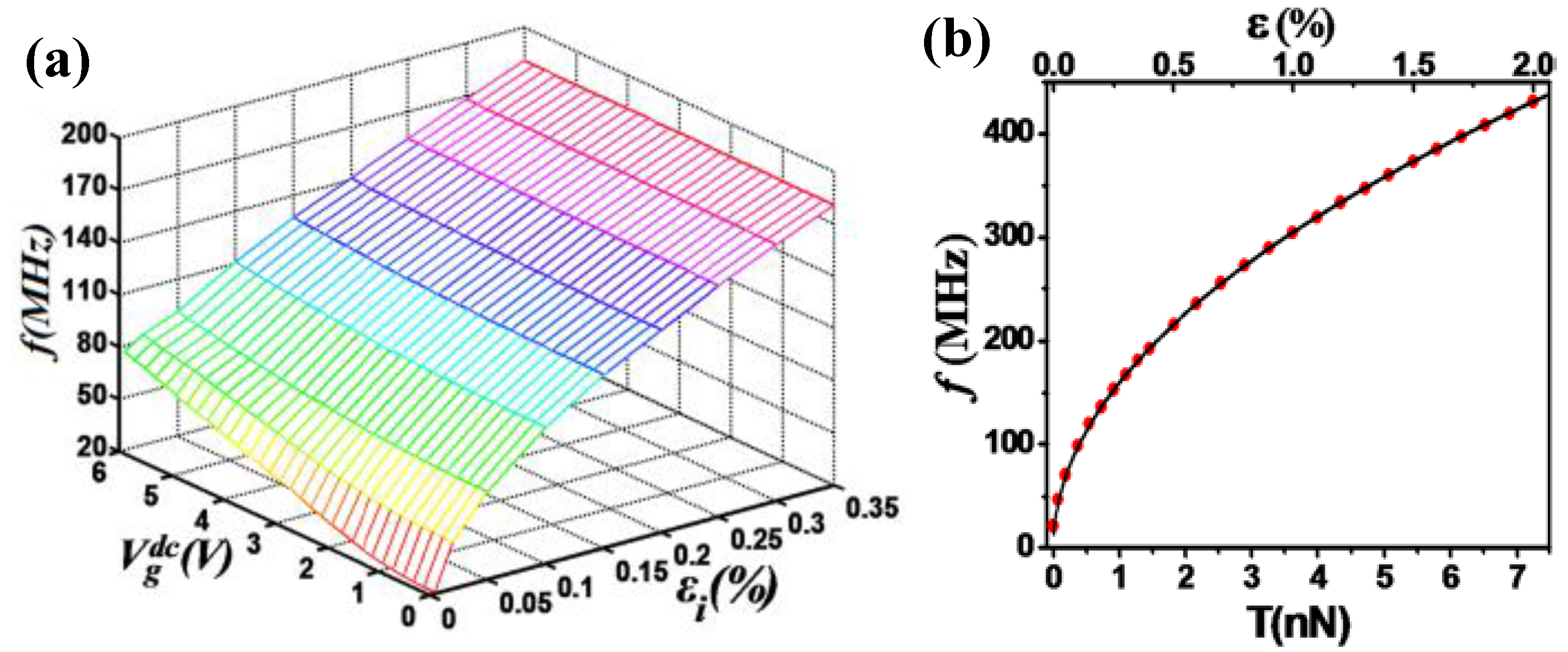
18].
6.2. Electrostatic Tuning Mechanism
6.2.1. General Tuning Model: Electrode Geometry
Electrostatic actuation remains an attractive method for frequency tuning due to virtually nonexistent current loss, high energy density, and large force at micro-scale [
280]. Since the pioneering experiments with charged soap-bubbles reported by Taylor [
281] and the invention of the first microresonators [
282], electrode geometries and support configurations in resonators have developed significantly [
283]. Electrode geometry has changed from being planar (graphene electrodes [
148]), to cylindrical (carbon nanotubes (CNT) [
214,
284] and nanowires [
17,
32]), to an array of cylinders (nanowire arrays [
285], nanotube arrays [
286]), and to fractal [
283,
287].
The resonant frequency can be tuned by the applied voltage and its dependence is well understood within the continuum mechanics framework [
286]. Palit
et al. [
283] and Jain and Alam [
288] presented a general framework to analyze electromechanical actuators having arbitrary electrode geometries and support configurations and reported the universal scaling relationships for resonant frequency depending on the scaling parameters.
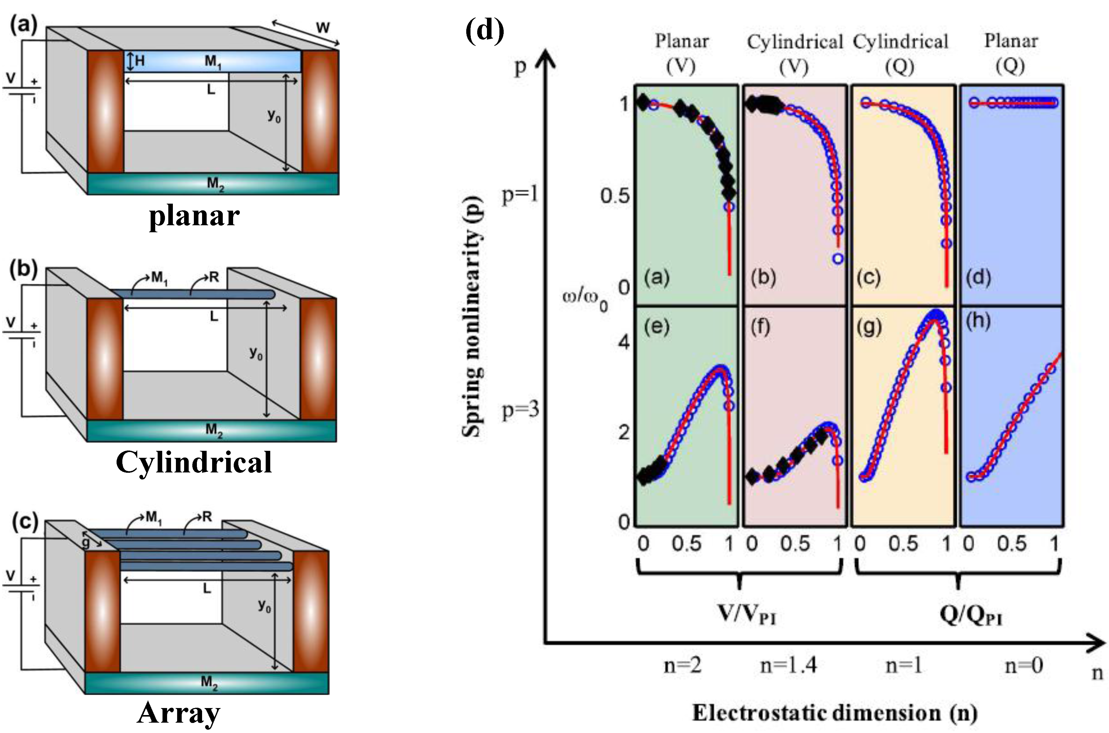
Figure 21a–c show the schematic of various movable electrodes
is suspended above a fixed bottom electrode
. The governing equation for the deflection
of
with Young’s modulus
, Poisson’s ratio
, thickness
, and subjected to an externally applied voltage
is given by [
283]:
where
is a vector in the plane of
and
is the capacitance per unit area between
and
at position
and given by
, in which
is the electrostatic dimension parameter that defines the electrostatics of the system,
is the effective dielectric thickness normalized by the dielectric constant,
is a constant that depends exclusively on the geometrical configuration of the electrodes.
Figure 21.
General electrode geometries for micro- and nano-mechanical resonators reported by Jain and Alam [
288]. (
a) Classical planar electrode; (
b) Cylindrical electrode; (
c) array of cylinders; (
d) Resonant frequency as a function of (V/Q) with scaling effect. Reused with permission from [
288].
With the increase of applied voltage
, separation between the two electrodes (
) is dictated by the balance of restoring spring and electrostatic forces. The application of potential
or
) not only changes the separation, but also modifies the effective stiffness
. The tuning of the resonant frequency with scaling effect can be given by [
288]:
where
is the initial air-gap
is the linear spring stiffness,
is the spring constant associated with the nonlinearity of order
.
Figure 21d illustrates the scaling relationship between the resonant frequency and applied potential
(or
) for various electrode geometries (planar and cylindrical electrodes). The expression Equation (65) reduces to
for a well-known resonant gate transistors [
282] with linear spring
and
) [
288]. Therefore, the resonant frequency of the resonators can electrically be tuned by applying a voltage between the electrodes.
6.2.2. Single-Electron Tuning
With the fields of electronics and mechanics making impressive progress toward quantum mechanical devices [
289], the combination of electronic transport with mechanics has become one of the exciting new areas during the past several years [
290]. The resonant frequency can be tuned by using an external electric means, which is convenient for practical applications [
291,
292].
Single-electron charge fluctuations can create periodic modulations of the resonant frequency of mechanical resonators [
293]. Steele
et al. [
293] and Lassagne
et al. [
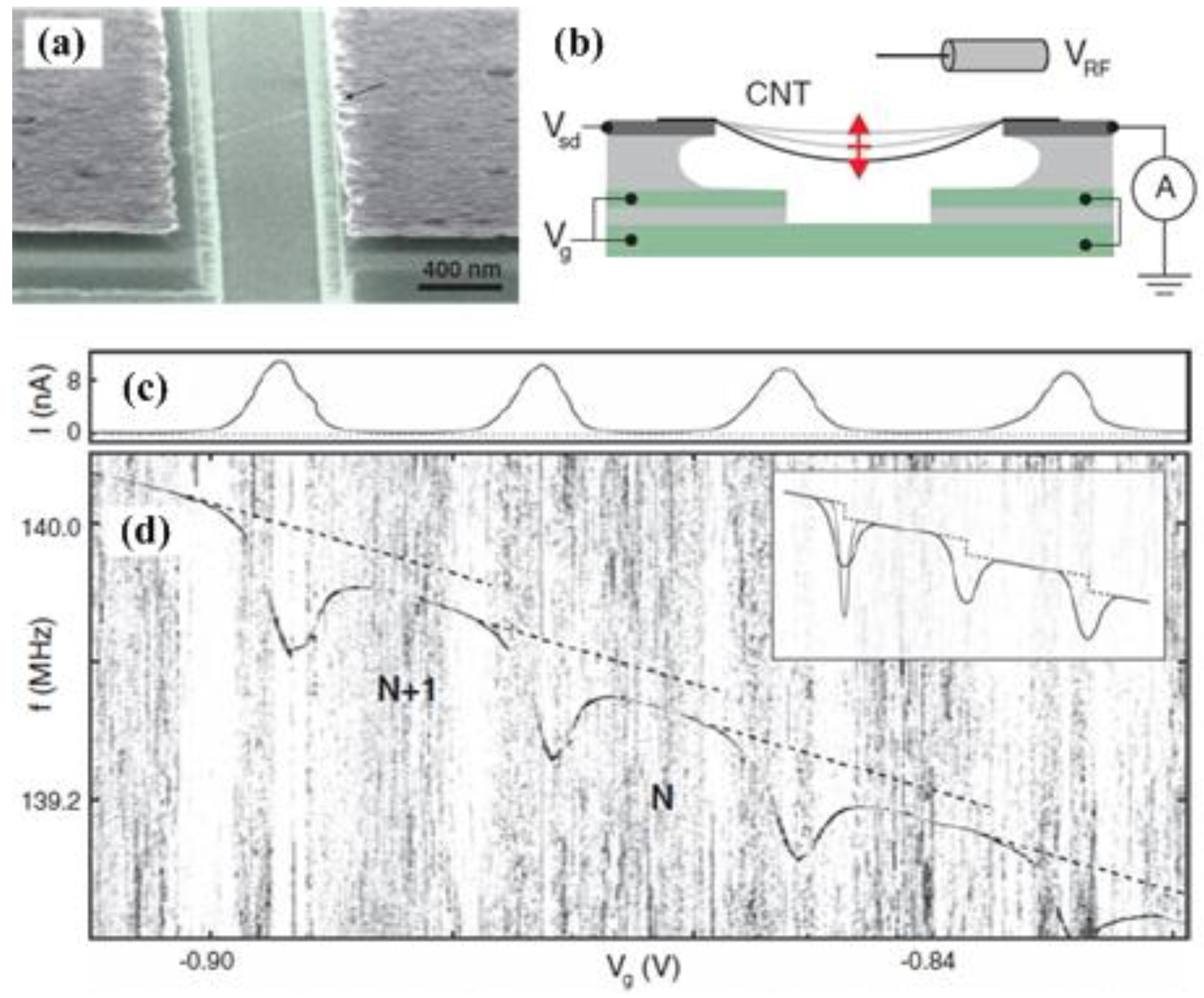
291] have found that the resonant frequency and dissipation in the nanotube mechanical resonators are both highly sensitive to the charge state with single electrons. As shown in
Figure 22, as the voltage is applied to the gate, the electrostatic force acting on the nanotube can be expressed as [
294]:
where
is the capacitance between the nanotube and the gate,
is the displacement of the fundamental model of the nanotube, and
and
(with frequency
) are the applied voltages on the gate and the nanotube, respectively. The resonant frequencies increase with gate voltage owing to the tensioning of the resonator [
31] and is tuned by more than a factor of 2 with the gate voltage [
293]. In the limiting cases, the fundamental resonant frequency can be given by [
295]:
where the variable
. The resonant frequency dependence
is associated with a loose string, while
represents that the string is tied.
Figure 22.
Single-electron tuning mechanism developed by Steele
et al. [
293]. (
a) Nanotube mechanical resonator; (
b) Device geometry for single-electron tuning; (
c) Single-electron Coulomb blockade oscillations; (
d) Tuning the resonant frequency with gate voltage. Reused with permission from [
293], Copyright 2009 American Association for the Advancement of Science.
When a single electron is added to the suspended CNT, the resonant frequency of the resonator dips dramatically due to the coupling between electronic and mechanical motion, which causes a softening of the spring constant. However, the resonant frequency changes non-smoothly and shows discrete jumps (
Figure 22d) due to the Coulomb blockade [
289]. This is the first experimental observation the electromechanical coupling of an electron in the quantum mechanical regime via CNT-based NEMS device. Solanki
et al. [
103] observed the nonmonotonic dispersion of the resonant frequency with dc gate voltage in nanowire resonators. More recently, Benyamini
et al. [
296] explored a new generation of suspended carbon nanotube mechanical resonators with wide-ranging local control. The key parameter in these experiments is the possibility of tuning the resonant frequencies by external gate electrodes [
214,
289,
290,
291,
293]. These gate electrodes can not only cause the microtubes to vibrate at their resonance modes, bust also introduce an axial strain which modifies the resonant frequencies significantly [
295,
297].
6.2.3. Capacitive Softening Effect
Resonant frequency of parallel-plate capacitive resonators can be tuned by changing the DC voltage applied across the sense and drive capacitive gaps. The principle is based on electrostatic force acting on the mass [
298], as shown in
Figure 23. The resonator structure contains an extra electrode system for resonant frequency tuning by applying a DC voltage and the tuning voltage
. The total stiffness
of the tuned resonator can be calculated as:
where
is the mechanical stiffness and
is the total capacitance between the two electrodes. The forces lead to a softening of the resonator system and result in decreasing the resonant frequency. A maximum tuning voltage of 35 V is required for continuous resonant frequency tuning from 1 to 10 kHz and a maximum resonance frequency shift of 0.7% [
298]. With sub-100 nm self-aligned vertical capacitive gaps designed for the first time, the resonant frequency can be tuned from 505 kHz to 450 kHz for the in-plane resonators by changing the DC voltage and providing a large electrostatic tuning range about 10% [
299]. The resonant frequency can be tuned down to −75% of its maximum value using electrostatic softening effect [
300]. Several measurements on the suspended metallized SiC beam, clamped-clamped InAs nanowire resonators [
15,
103], and CNT mechanical resonators [
155] have also displayed the decrease of resonant frequency due to the electrostatic softening of the vibration.
Figure 23.
Resonant frequency tuning by capacitive softening effect.
Figure 23.
Resonant frequency tuning by capacitive softening effect.
Recently, Eriksson
et al. [
301] discussed the coupled effects of deflection-induced tension and electrostatic softening on the resonant frequency tuning of circular nanomechanical graphene resonators.
6.2.4. Combination of Hardening and Softening Effects
Micro- and nano-resonators actuated by electrostatic force can offer
in situ frequency tuning over wide frequency range [
31,
108,
184]. The frequency tuning is known to be governed by two distinct mechanisms: the elastic hardening effect, which arises in the presence of large elastic deformations and increases the resonance frequencies, and the capacitive softening effect, which is inherent to the electrostatic actuation force and decreases the resonance frequencies [
15,
302,
303]. The resonant frequency has been observed to tune either upward [
31] or downward [
10], and both states [
15,
215].
As one of the most representative electrostatic tuning methods, Kozinsky
et al. [
15] demonstrated an ability to tune the resonant frequency of resonators both upward and downward.
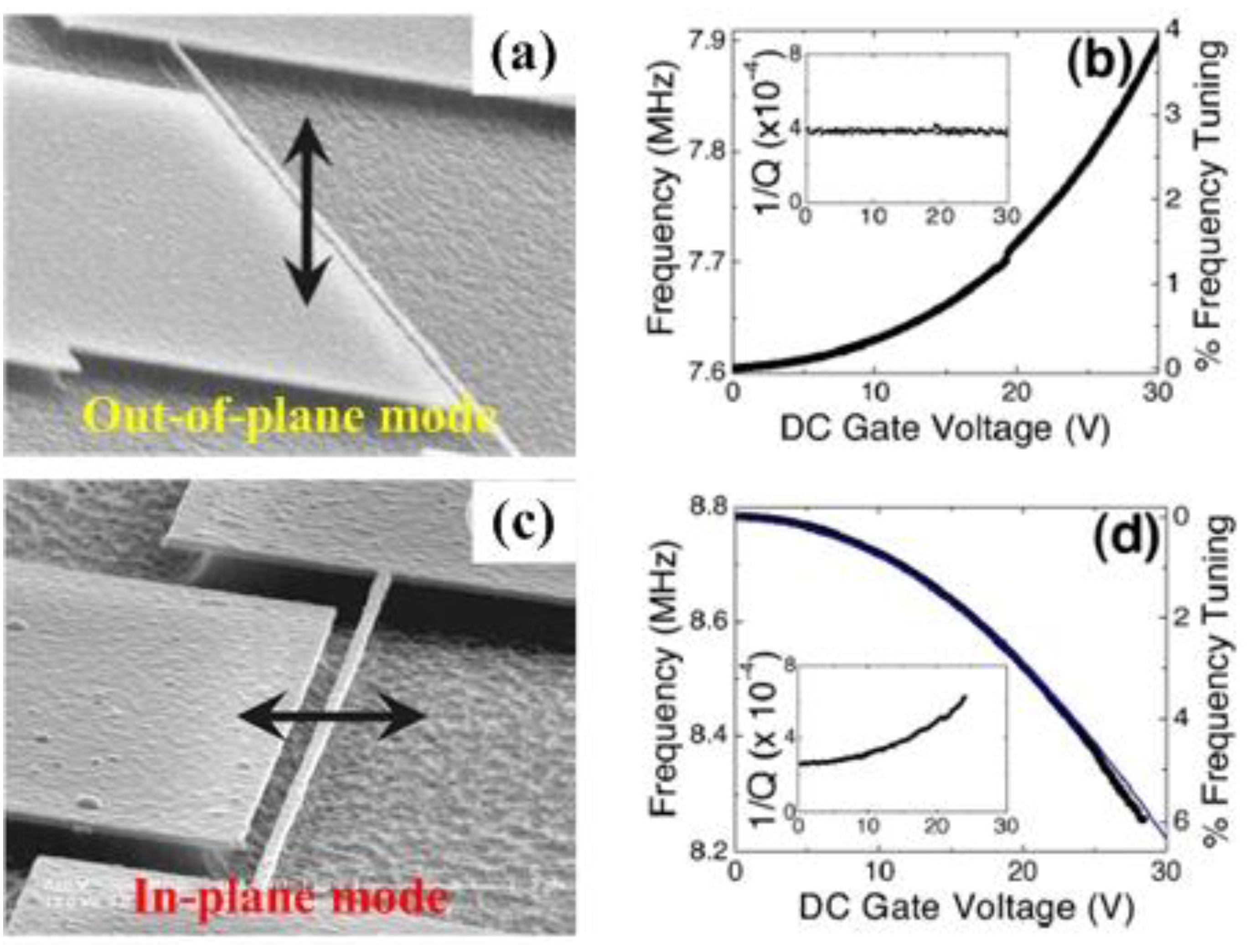
Figure 24 illustrates the electrostatic tuning setup and measurement, and shows the results obtained by varying the DC bias applied to the gate electrode. Both softening and hardening types of frequency tuning in the resonator were observed. As shown in
Figure 24a,b, the resonant frequency of the beam with gate voltage increases when the out-of-plane mode of vibration occurs. As the applied DC gate voltage increases, the resonant frequency increases. For the in-plane mode, it can be observed from
Figure 24c,d that the decrease in the resonant frequency. The clamped-clamped beam is electrostatically attracted to the gate and results in the spring constant becoming smaller. Under the combination effect of electrostatic force and elastic restoring force, the governing equation can be given by [
15]:
where
is the residual tension,
is the bending-induced tension and
, the electrostatic force
, in which
is the capacitance per unit length and
is a time-varying AC displacement. Electrostatic force on the nanotube leads to a deflection towards the gate and results in the increased mechanical tension [
31,
294]. The resonant frequency can be obtained as [
15]:
where
is the capacitance expansion coefficient,
is static deflection amplitude. The different frequency tuning behaviors can also explained by Equation (70). The frequency increases in the out-of-plane mode due to increasing the gate voltage, which only stretches the beam. For the in-plane vibration mode, both stretching and electrostatic attraction occurs. Electrostatic attraction to the gate has the softening effect on the resonator for lower gate voltage before the hardening due to the stretching effect [
15]. The theoretical expression for resonant frequency Equation (70) agrees well with the experimental data as shown in
Figure 24d. The limitation of frequency tuning using electrostatic spring softening effect is that only one directional tuning is available.
On one hand, when a DC bias voltage
is applied to the gate and a potential difference is created, the resulting electrostatic force attracts the resonator toward the gate and results in induced-tension in the resonator. The elastic hardening effect increases the resonant frequency which can be given by [
215,
302]:
where
is the static displacement of the center of the beam and
, in which
is the first derivative of capacitance,
is the diameter of the cylindrical wire.
On the other hand, when the DC voltage
is applied to side gate, the electrostatic force is in the direction of the resonator and the bias not only creates tension but also results in the capacitive softening effects [
302]. The capacitive coupling between the electrodes allows electrostatic control of both the mean position of the resonator and its resonance frequency. The frequency dependence of the capacitive softening effect can be expressed as [
15,
215,
302]:
where
is the second derivative of capacitance.
Figure 24.
Electrostatic tuning setup and measurement reported by Kozinsky
et al. [
15]. (
a) The beam’s vibration out-of-plane with the gate; (
b) Elastic tuning of resonant frequency upward; (
c) The beam’s vibration in-plane of the gate; (
d) Capacitive tuning of resonant frequency downward. Reused with permission from [
15], Copyright 2006, American Institute of Physics.
SWNT resonators are known to have multiple vibrational states, including out-of-plane, in-plane, and the higher order modes [
31,
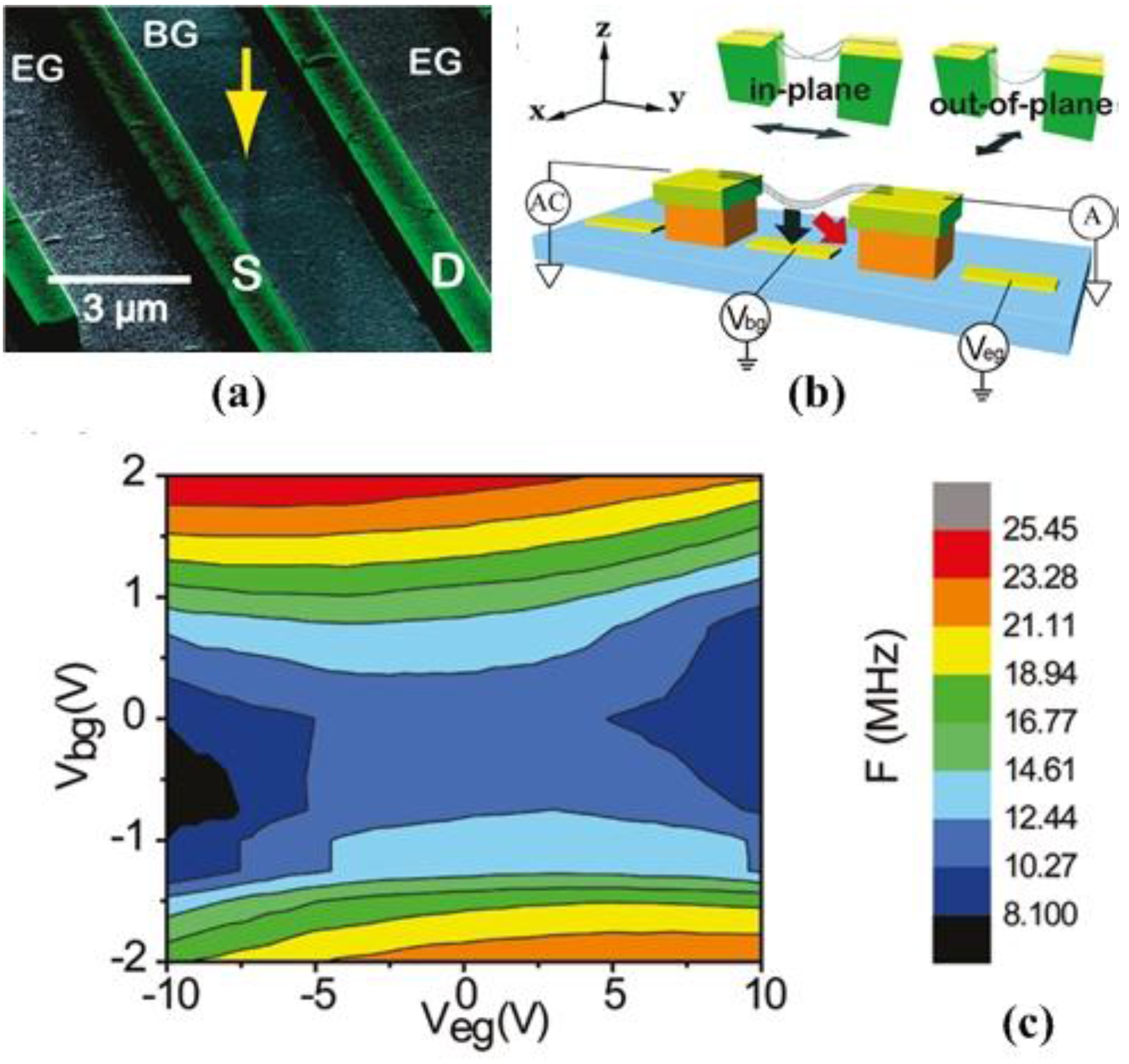
215]. Wu and Zhong [
215] first investigated the frequency tuning using bottom-gate electrode, and reported the observation of the dual-gate nanotube resonators (
Figure 25a) can realize frequency tuning through both elastic hardening and capacitive softening mechanisms, as illustrated in
Figure 25b. The coupling of bottom-gate (BG) and end-gate (EG) effects on the capacitive softening was taken into account. The capacitive softening equation can be modified by including the effect of elastic hardening and an offset voltage
as:
where
and
are the elastic hardening tuning and capacitive softening coefficients, respectively.
Figure 25c shows a two-dimensional plot of resonant frequency as a function of
and
. The resonant frequencies illustrate symmetric tuning around gate voltages corresponding to the charge neutral point.
Figure 25.
Device geometry and dual-gate frequency tuning of single-walled carbon nanotube (SWNT) resonator reported by Wu and Zhong [
215]. (
a) Dual-gate nanotube resonators; (
b) Frequency tuning through both elastic hardening and capacitive softening mechanisms; (
c) Resonant frequency as a function of
and
. Reused with permission from [
215], Copyright 2011, American Chemical Society.
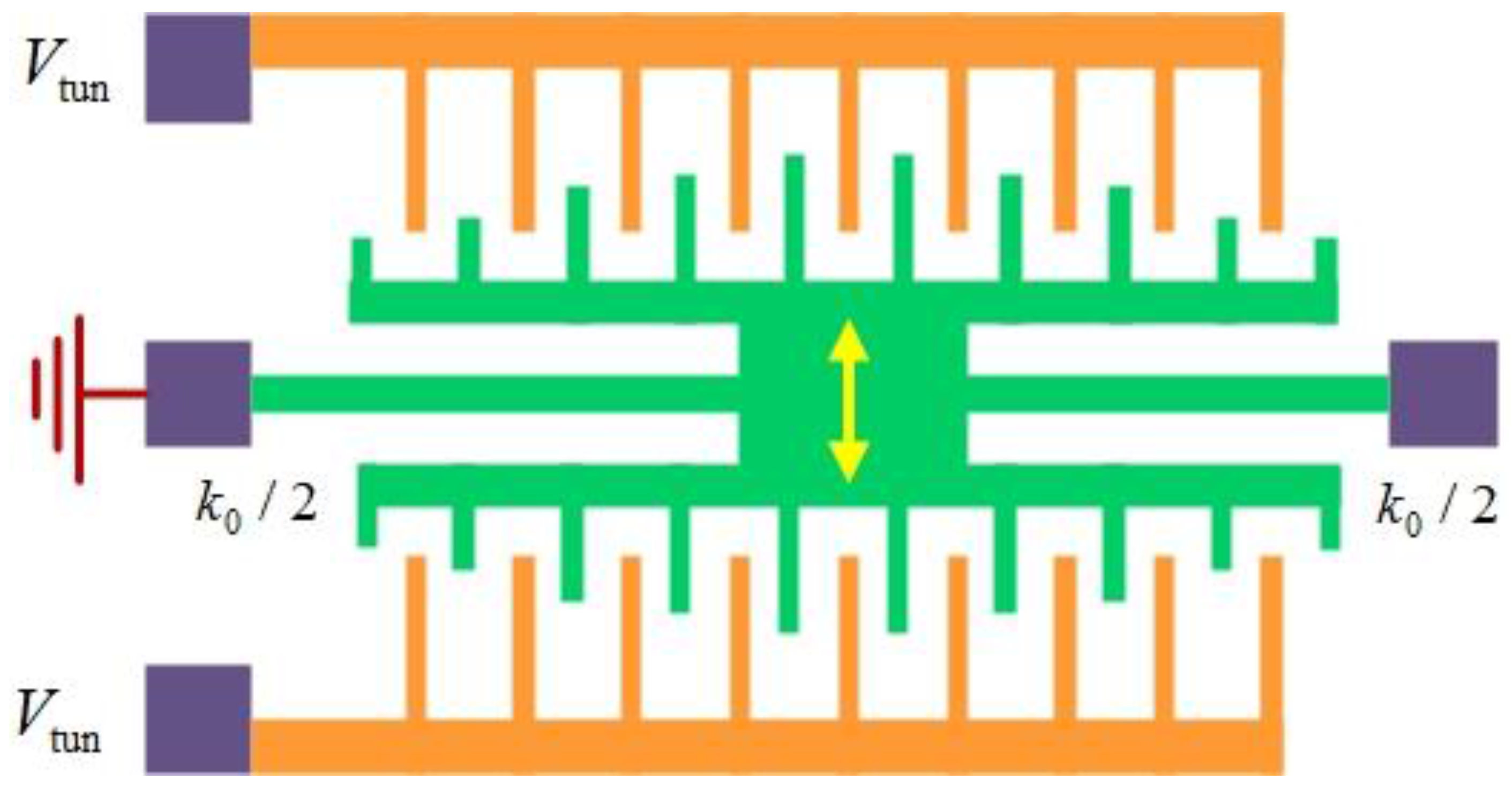
6.2.5. Frequency Tuning for Comb-Drive Microresonators
To achieve wide frequency tuning range with low power consumption, many researchers have focused on various comb finger designs. Various frequency tuning methods have been applied and demonstrated for comb-drive microresonators, as listed in
Table 8.
Electrostatic comb structures have been the key design elements for comb-drive micromechanical resonators [
304,
305,
306,
307,
308,
309,
310,
311,
312,
313,
314,
315]. Multiple tuning approaches have been presented to tune the effective spring constant of the resonators, including parallel-plate [
20], fringing field [
304], and variable gap comb-drives [
305,
306]. Lee and Cho [
21] applied a control voltage for triangular electrostatic comb arrays for 3.3% reduction in the resonant frequency. Adding material deposition to the mass can lead to 1.2% resonant frequency reduction [
89]. The use of constrained thermal expansion can result in 50% increase in the resonant frequency under vacuum and 25% frequency reduction at atmospheric pressure [
19]. These tuning methods provide small change in resonant frequency [
21,
89] or require high power for frequency tuning operations [
19]. Furthermore, under the applied external electrical potential and Joule heating effects, the resonant frequencies of the comb drive resonators change from 22.2 kHz to 16.2 kHz, resulting in the 27% reduction in the resonant frequency [
307].
Table 8.
Various frequency tuning methods for the comb-drive microresonators [19,21,89,298,305,310,311,313,314,315].
| Reference | Tuning Mechanism/Method | Geometry Configuration | Active/Passive Method | Resonant Frequency | Tuning Range |
|---|
| Lee and Cho [21] | The DC-biased electrostatic tuning comb structures arranged in the triangular shape to adjust the resonant frequency using the linear electrostatic force. | Triangular comb arrays | Active method | 2.42 kHz | −3.3% (measurement); −5.3% (estimation) |
| Syms [19] | The use of constrained thermal expansion to tune the resonant frequency. The tensile strains may be set up in the suspension using a folded geometry. | Folded geometry | Active method | 1.56 kHz | −25% (at atmospheric pressure);
50% (at 10 mTorr) |
| Lee et al. [313] | A closed-form design approach for comb finger profiles to achieve constant electrostatic stiffness or linear electrostatic force. | Curved comb finger | Active method | 19 kHz | −55% (measurement); −45.4% (theoretical result); −42.7% (simulation) |
| Jensen et al. [305] | Shaped fingers allow the design of resonators operating at a wide range of spring stiffness and tuning resonant frequency over a large range. | weakening fingers | Active method | 4.3 kHz | 165 Hz (downward) |
| stiffening fingers | 5.3 kHz (upward) |
| Xu and Tsai [310] | The basic idea is to synthesize the design of the supported springs and the releasing holes in the proof mass. Then the process-induced effective spring constant variation can be balanced by effective mass variation. | DRIE-induced variation | Active method | 3.28 kHz | 2.1% |
| Zine-El-Abidine and Yang [311] | The suspension configuration can be mechanically altered to change its spring constant. | Curved electrode | Active method | 10.8 kHz | 17.6 kHz (two actuators); 21.4 kHz (four actuators) |
| Scheibner et al. [298] | The principle is based on electrostatically generated, amplitude-dependent forces acting on the seismic mass, and the structures implement electrostatic softening effect. | Capacitive surfaces | Active method | 2.89 kHz | 901 Hz |
| Morgan and Ghodssi [314] | The vertically-shaped comb-fingers were designed as electrostatic springs without increasing the device area. | Shaped fingers | Active method | 1.6 kHz | 17% (bidirectional) |
| Joachim and Lin [315] | The selective deposition of polysilicon by silane decomposition on electrically heated, released microstructures. | Selectively deposited polysilicon | Passive method | 86.6 kHz | 1.96% |
| Chiao and Lin [89] | Post-packaging tuning process for microresonators by pulsed laser deposition (PLD). The advantages include precise process control, versatility and easy implementation. | donor film structure | Passive method | 12.37 kHz | −1.2% |
Various comb finger configurations had been designed to achieve wide frequency tuning with low power consumption [
316]. The shaped comb design was previously made to maximize the electrostatic force by a segmented comb with different widths [
306]. Adams
et al. [
39] presented four electrostatic actuators to change the stiffness and tune the resonant frequency upwards to 146% and downwards to 7.7% of the original values. The planar shaped combs for delivering electrostatic force with specific nonlinearity and the resonant frequency can be tuned either downwards or upwards [
305]. A specific varying-gap comb-finger design for a large-stroke parametric resonator was recently reported in [
308]. A new truss electrode presented by Khirallah [
309] can produce time-varying electrostatic axial force on the resonator and consequently modulate its effective spring constant. Xu and Tsai [
310] presented an interesting method to seek the proper parameter sets to balance the variations of process-induced spring constant and mass. The resonant frequencies are in the range of 32 102 ± 25 Hz and obey basically the normal distribution. The stiffening or the weakening of the comb allows the resonant frequency to be swept between the multiple frequencies of the comb achieving a very wide tuning range [
311]. Zhong
et al. [
312] demonstrated an interesting result of the inclination effect on the frequency tuning of comb-driven resonators. Although these methods obtained tunability, small variation of the resonant frequency can be tuned for the micromechanical resonators.
In addition, the ultimate limit to electrostatic tuning in micro- and nano-resonators depends on the pull-in effect when the beam structure gets close enough to the gate [
15]. The major drawback of this scheme is that the response is nonlinear. On the contrary, electrostatic pull-in can also be used for micro- and nanomechanical resonators [
316]. Kafumbe
et al. [
40] explored a new method of actively tuning the resonant frequency of microresonators using electrostatic pull-in to adjust the length of the resonating structure and guarantees frequency tuning throughout the lifetime of the device. Ke [
317] presented the theoretical investigation of double-sided excitation scheme for resonant frequency tuning of nanotube resonators with table range reaching up to 90% of the gap between the actuation electrodes, which exceeds the resonant pull-in limit. Pull-in has also been proposed for sensing adsorbate stiffness in nanomechanical resonators [
318].
6.2.6. Photothermal Tuning Mechanism
Optical techniques have the advantages of requiring no electrical connections, possessing the highest resolution, and can be implemented for measurements of the resonators in vacuum, gas, and liquids [
23,
319]. The resonant properties of micro- and nano-mechanical resonators driven by the photothermal approach contain rich information about mechanical and thermal properties of the resonating system [
320,
321]. The resonant frequencies of nanocantilevers can be influenced by the optical pressure and photothermal force generated by the laser beam probe [
94,
322,
323].
The photothermal effect can be used to tune the frequency of micro- and nano-resonators [
45,
324,
325,
326]. Kim
et al. [
325] demonstrated the pressure-sensing scheme based on the photothermal effect in the miniaturized beam resonator, and observed the considerable decrease in the resonant frequency due to the photothermally induced compressive stress. Incident optical power results in the temperature rise in the composite beam and the shift in the resonance frequency due to thermal stress [
324]. Photothermal actuation was also used for the self-excitation and for measuring the resonant frequency of nanomechanical resonators in liquids [
94,
327]. The immense resonant frequency tunability available by this technique may be of importance for numerous NEMS applications [
45].
To understand the effect of the laser power on the dynamic response of the resonators, the resonance spectra at multiple harmonic modes were taken at various power levels [
324]. Kim
et al. [
324] determined the amount of incident power
on the beam by considering the Gaussian distribution as:
where
is the reflectivity,
is the maximum intensity from the total optical power measurement,
is the experimental optical spot size. The corresponding temperature distribution
caused by the laser power can be calculated from the heat conduction model with Gaussian thermal source as:
where
,
and
are the weighted average of thermal conductivity, mass density and heat capacity, respectively,
is the total thickness,
is the ambient temperature, and
is the heat transfer coefficient. The observed resonant frequency decreases with the optical power due to the heating of the resonator, generating the photothermal stress. Under the axial stress, the resonant frequency of a clamped-clamped beam at
th mode can be given by [
324]:
where the axial stress
is a sum of the intrinsic stress
due to the SiN layer deposition and fabrication processes, and the temperature-dependent thermal stress
. The effect of the photothermal stress on the dynamics of the beam resonator can be more easily found in the square of the resonant frequency
. It can be clearly observed that the linear dependence of
on
at several modes, which is expected from Equation (76). The inset shows the average temperature rise
as a function of incident optical power
calculated from the heat conduction model with a Gaussian thermal source.
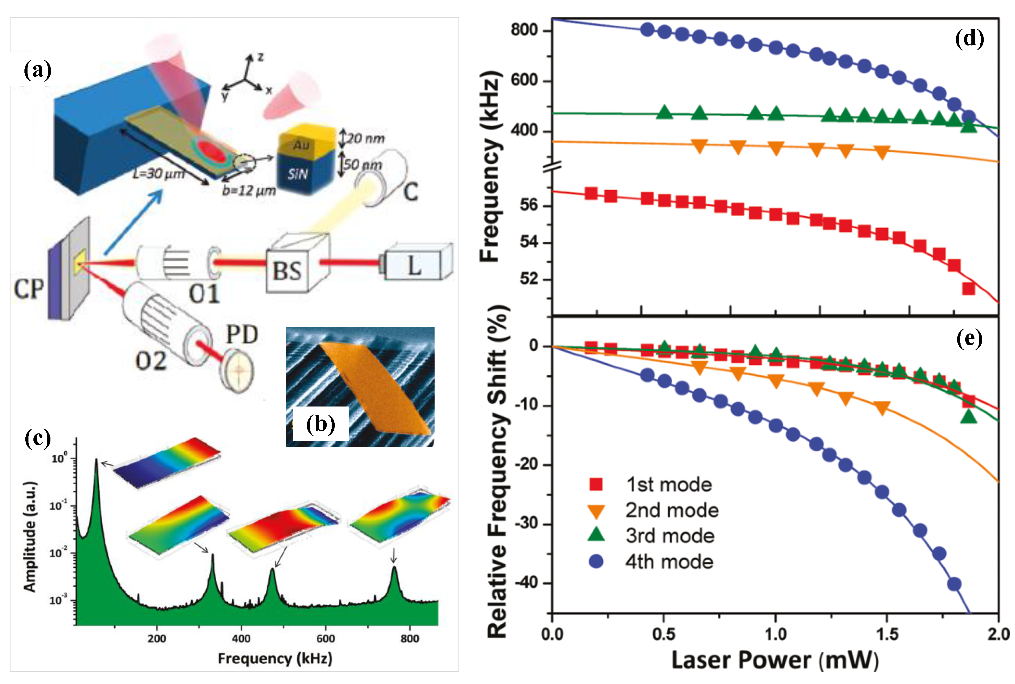
Notably, Pini
et al. [
319] indicated that the light back-action effect is very significant in ultrathin bimetallic cantilevers and demonstrated that the laser beam used for probing the mechanical state of nanomechanical resonators can extraordinarily shift the resonant frequencies.
Figure 26a illustrated the schematic of the optical detection and the cantilever structure (
Figure 26b). A typical frequency spectrum of the thermomechanical noise of the fabricated cantilevers was shown in
Figure 26c.
Figure 26d,e plotted the first four resonant frequencies and frequency shift of the cantilever as a function of the laser power. It can be found that the laser power increase gives rise to a decrease of the resonant frequency of about 30%. Interestingly, the resonant frequency shifts follow a nonlinear behavior with the laser power. The tunable optical gradient force can also cause the frequency shift in resonators [
328]. In addition, the frequency shift due to the laser back-action effect follows a nonlinear behavior, which reveals a new mechanism of resonance frequency shift due to in-plane stress.
Figure 26.
Laser-induced resonant frequency shift reported by Pini
et al. [
319]. (
a) Schematic diagram of the structure and dimensions of the laser beam deflection technique; (
b) SEM of the fabricated bimetallic cantilever; (
c) Frequency spectrum of the thermomechanical fluctuations; (
d) First four resonant frequencies of the cantilever as a function of the laser power intensity; (
e) The relative frequency shifts. Reused with permission from [
319], Copyright 2011, American Chemical Society.
6.2.7. Piezoelectric Tuning Mechanism
As one of the earliest and most straightforward actuation methods, piezoelectric transduction technique provides a means of directly converting an electric field into mechanical strain [
42]. The piezoelectric transduction technique and actuation scheme also enables the resonant frequency of the mechanical oscillator to be tuned [
329,
330]. The ability to control the effective spring constant using the piezoelectric effect enables excitation of the fundamental mode through parametric resonance [
43,
331].
Using a p-type/intrinsic/n-type diode structure, Masmanidis
et al. [
42] investigated the use of piezoelectric semiconductors as active structural materials for nanomechanical resonators. The remarkable feature due to the piezoelectric effect is voltage-induced resonant frequency control, as shown in
Figure 27. Resonant frequency shifts are clearly observed upon the DC-biasing of the clamped-clamped beam resonator (
Figure 27b). In the case of small perturbations, frequency shift
can be quantitatively expressed as:
where
is the anisotropic piezoelectric coefficient,
is the elastic Young’s modulus and
is the density
is the total device thickness,
is the DC bias voltage. It can be found that this expression implies linear frequency-voltage dependence.
Figure 27.
Piezoelectric resonant frequency control and tuning [
42]. (
a) Clamped-clamped beam which used to gauge the efficiency of piezoelectric excitation; (
b) Frequency response near the fundamental out-of-plane resonant mode; (
c) Measurements of resonant frequency shift as a function of DC bias voltage. Reused with permission from [
42], Copyright 2007 American Association for the Advancement of Science.
Due to the anisotropic nature of the piezoelectric coefficient, the slop of
can be controlled and tuned by fabricating the beam along a prescribed direction [
42], as illustrated in
Figure 27c. The equal and opposite tuning slope of devices aligned along the (110) and (–110) directions is characterized by the opposite sign of
along these directions. In addition, the potential application of voltage-dependent frequency tuning for piezoelectric nanomechanical charge sensing was also demonstrated. However, the bandwidth of a piezoelectric actuator depends upon the relaxation time of the deformations after the electric field is removed [
264]. Utilizing the actuation of mechanical resonance with the same phenomenon demonstrated in [
42], Mahboob and Yamaguchi [
43] designed a device excited by the piezoelectric effect by applying an AC voltage. In the clamped beam, the application of a DC voltage leads to strain along the beam via the piezoelectric effect enabling the resonant frequency to be tuned. The resonant frequency shift by controlling of the effective spring constant permits the implementation of parametric resonance as well as on-chip electromechanical charge sensing [
43]. Piezoelectricity encountered in some materials is one of the unexplored phenomena with potential in nano-scale [
264].
6.3. Dielectric Tuning Mechanism
Actuation techniques based on dielectric gradient forces, which are becoming more and more powerful tool to tune and control MEMS/NEMS devices [
34,
332,
333]. If the dielectric beam is placed in between two vertically offset electrodes, its vibration can lead to the periodic modulation of their mutual capacitance [
334]. Efficient integrated actuation and read-out schemes have been developed to detect the motion of resonators [
264]. For example, the resonant frequency can be tuned by capacitive coupling of the nanomechanical element to a side electrode [
15]. However, the required metalization of the resonant structure reduces the quality factor significantly via Ohmic losses [
335]. For this Faust
et al. [
334] developed an efficient, room-temperature microwave mixing scheme for readout as well as a dielectric drive mechanism to actuate mechanics regardless of the material makeup [
34].
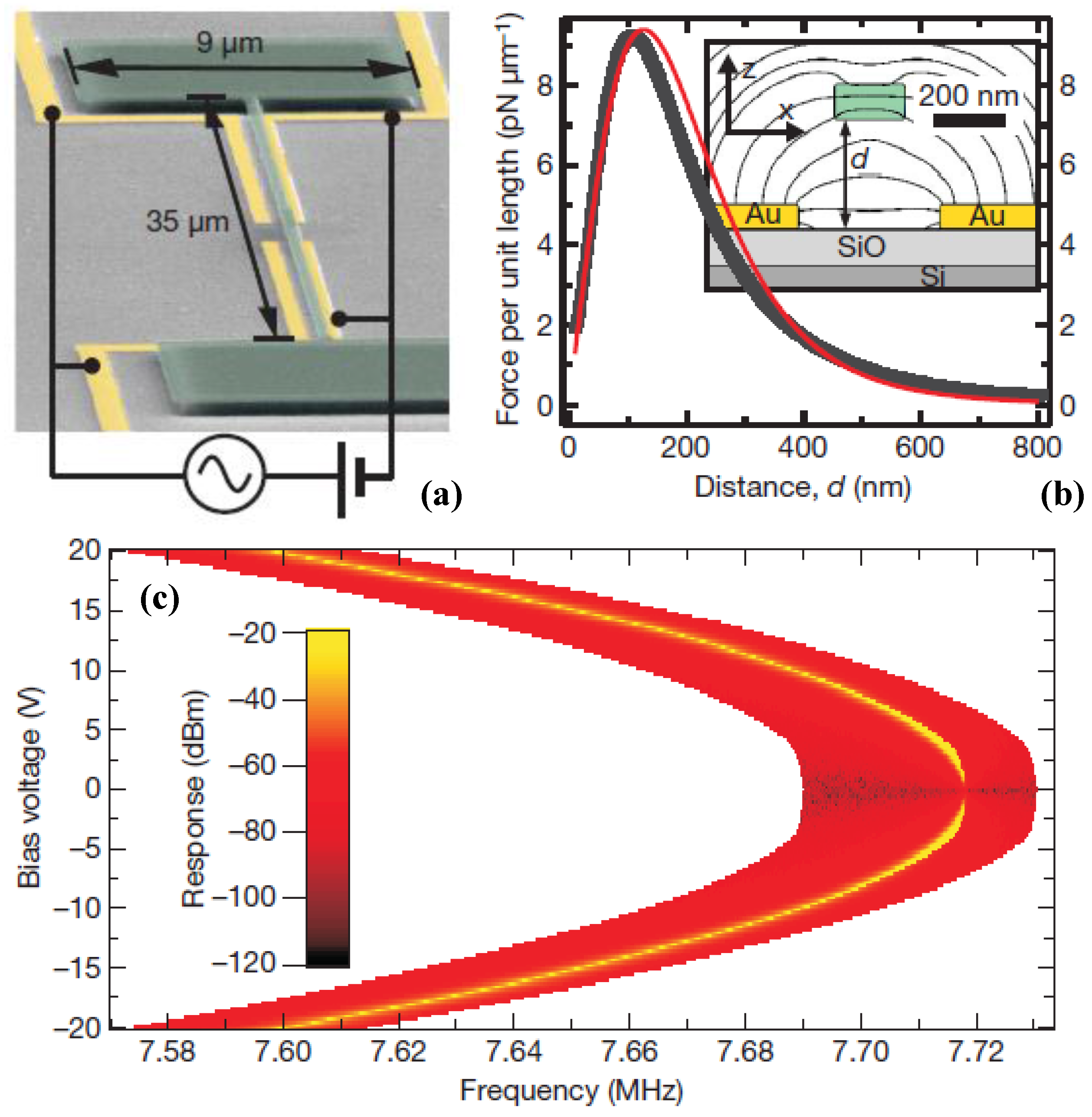
Any polarizable body placed in an inhomogeneous electric field implements a dielectric force, Unterreithmeier
et al. [
34] demonstrated the design of a set of on-chip electrodes to create an electric field gradient and polarize a dielectric resonator and subject it to an attractive force than can be modulated at high frequencies. The mechanism relies mainly on dielectric interaction, in which the polarizable element is a clamped-clamped silicon nitride beam (
Figure 28a). The scheme enables simple voltage tuning of the mechanical resonance over a wide frequency range due the dielectric force depending strongly on the resonator-electrode separation. The dielectric force exhibits a maximum at a distance that is comparable, as shown in
Figure 28b. The modulation of the resonant frequency can be used to demonstrate parametric actuation [
43]. Unterreithmeier
et al. [
34] and Rieger
et al. [
333] found that the force gradient to be proportional to the square of the voltage.
Figure 28.
(
a) SEM of a nanomechanical resonator reported by Unterreithmeier
et al. [
34]; (
b) The dielectric force acting on the resonator; (
c) Frequency tuning of the resonator. Reused with permission from [
34], Copyright 2009, Nature Publishing Group.
Figure 28.
(
a) SEM of a nanomechanical resonator reported by Unterreithmeier
et al. [
34]; (
b) The dielectric force acting on the resonator; (
c) Frequency tuning of the resonator. Reused with permission from [
34], Copyright 2009, Nature Publishing Group.
A quadratic dependence of the resonator resonance frequency on the applied dc voltage can be derived from the energy of the induced dipolar moment of the dielectric resonator in an external electric field [
333]. The resulting shift in resonant frequency can be expressed as [
34]:
where
is a constant and relative to the field gradient. The resonance frequency decreases quadratically with bias voltage, as illustrated in
Figure 28c. The resonant frequency lies between 5 and 9 MHz and the frequency tuning range of more than 100 kHz, while the quality factor ranges from 100,000 to 150,000 [
34]. Rieger
et al. [
333] presented an integrated scheme for dielectric drive and read-out of high-Q nanomechanical resonators that enable tuning of both the resonance frequency and quality factor with an applied DC voltage. The resonance frequencies lie around 6.5 MHz and can be tuned over 5% [
333], and the highest quality factor is 340 000 for the out-of-plane mode in the elevated design. Unterreithmeier
et al. [
336] successfully modeled the damping of nanoresonators by postulating a frequency-independent mechanism caused by local strain variation. The large frequency tuning range can be used for
in-situ tuning of several mechanical elements into resonance [
337] or coupling to external elements [
338]. In addition, altering the DC voltage does not only shift the resonant frequency, but also influences the dielectrically induced damping which varies quadratically with increasing voltage [
15,
333].
6.4. Magnetomotive Tuning Mechanism
The magnetomotive transduction technique [
41,
123,
339] has played a very important role in the micro- and nanomechanical resonators [
1,
111], and allows for all-electrical actuation and sensing of the mechanical motion. Although magnetomotive actuation technique is broadband, even in the presence of parasitic capacitances [
123], it requires strong magnetic fields, which are usually generated by using superconducting coils [
1], and the eddy current damping force caused by this transduction scheme should be examined [
10].
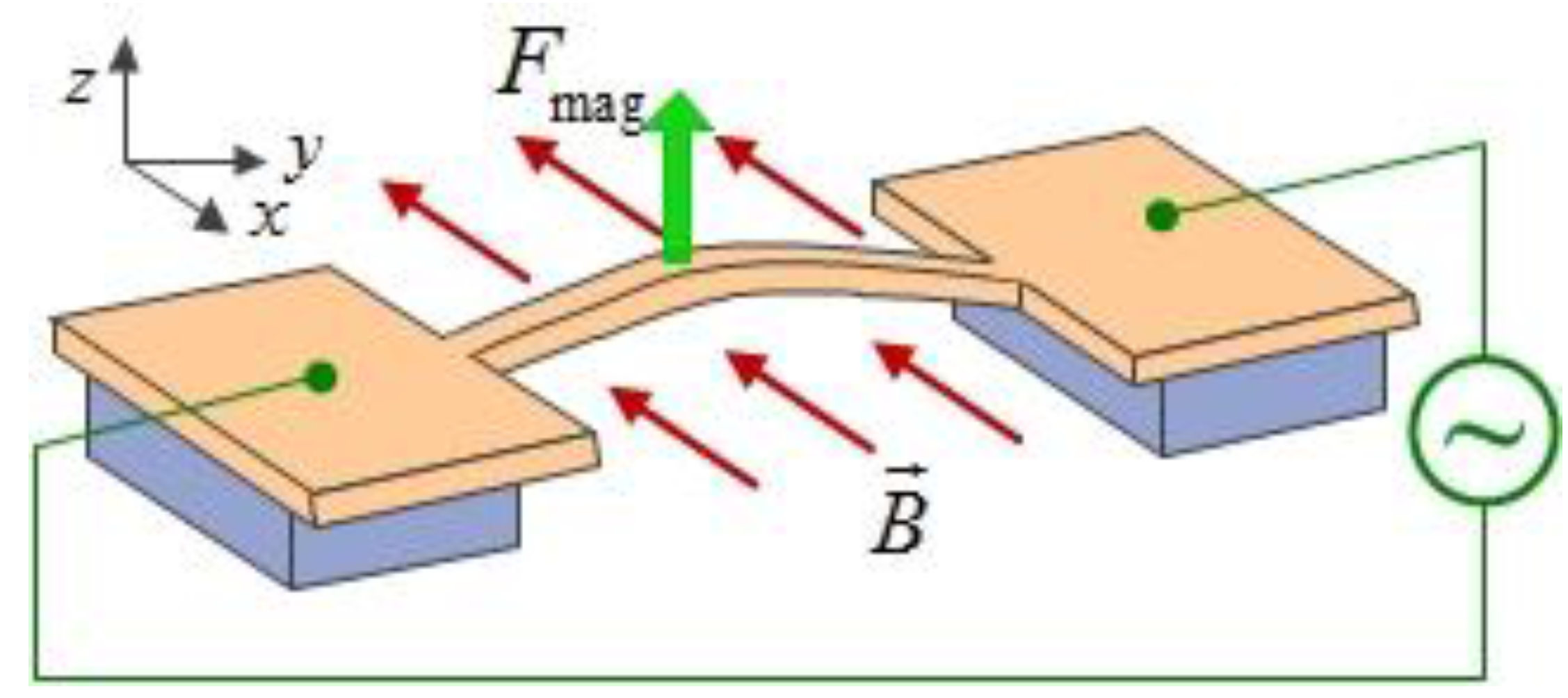
The magnetomotive coupling scheme is based on the electrodynamic forces that act on moving charges in a magnetic field [
107], and it can be used for SiC and AlN resonator structures. The scheme is shown in
Figure 29 in a doubly clamped beam. An external voltage is applied between both contact areas on either side of the freestanding structure. Due to the applied magnetic field
, an alternating Lorentz force is generated in the out-of-plane direction. The Lorentz force
depending on the alternating current
can be expressed as:
where
is the length of the beam. The induced electromotive force developed along the beam owes to its resulting motion through the magnetic field [
41]. A combination of capacitive and magnetomotive excitation for the tunable coupled nanomechanical resonators was reported in [
340].
Figure 29.
Schematic of magnetomotive actuation for the doubly clamped beam resonator.
Figure 29.
Schematic of magnetomotive actuation for the doubly clamped beam resonator.
6.5. Mode Coupling Tuning Mechanism
As an effective tuning mechanism, the mode coupling of nanomechanical resonators has been intensively investigated during the past several years. Mode coupling can be generally divided into intermodal coupling and the mode coupling between mechanical modes and the other types of modes. The former category mainly includes tension-induced modal coupling [
341,
342,
343,
344], the coupling in the single-electron tunneling regime [
47,
289,
293], the coupling in quantum regime [
345]. Parametric mode fixing [
346] and the mode coupling between different resonators [
347,
348] belong to the latter. The mode-coupling also provides a dissipation channel for the fundamental mode dynamics in resonators [
349]. In addition, according to the coupling strength, mode coupling can be classified into linear coupling [
341,
342,
350] and nonlinear coupling [
46,
343,
344].
In order to clearly understand the coupling between the flexural modes of the resonators, several analytical models were introduced [
46,
47]. The equation for describing the motion of mode
with considering the modal interactions can be expressed as [
47]:
where
,
and
are the damping, resonant frequency and driving force of mode
, respectively, and the indices
represents the number of modes considered. It can be simplified to be the Duffing equation of a nonlinear resonator for a single mode at
. The parameter
is strongly influenced by the single-electron tunneling processes in the suspended carbon nanotube [
293], and the displacement-induced tension in the micromechanical resonators [
46].
Castellanos-Gomez
et al. [
47] reported that the resonant frequency can be tuned by the modal interactions between the two vibration modes of the carbon nanotube. As shown in
Figure 30a–c, three different situations were presented the mechanism, (a) mode softening: the modal interaction reduces the resonant frequency of another mode; (b) mode stiffening: the modal interaction increases the resonance frequency of another mode; and (c) modal interaction suppression: the effect of the modal interaction can be negligible. The modal interaction dominated by single-electron-tunneling processes [
293] was verified qualitatively when adjusting the gate voltage, and the frequency tuning by the modal interactions as a function of the gate voltage can be seen in
Figure 30d,e. The maximum change in the resonant frequency due to the modal interaction illustrates that a continuous transition from stiffening to softening effects, and the sign of the modal interaction is directly related to that of the nonlinear spring of the carbon nanotube. In addition, the modal interaction strength can continuously by tuned from
(stiffening) to
(softening), which is about 6 orders of magnitude larger than that in micromechanical resonators [
46]. The nonlinear intrinsic coupling between the flexural–flexural, torsional–torsional and flexural–torsional modes of a microcantilever was experimentally reported in [
351]. The direct bending-induced nonlinearities can be identified to facilitate the precise tuning of nanomechanical resonators [
352].
Figure 30.
Resonant frequency tuning using the modal interactions reported by Castellanos-Gomez
et al. [
47]. (
a) Mode softening; (
b) mode stiffening; (
c) modal interaction suppression; (
d) and (
e) Frequency tuning by the modal interactions as a function of the gate voltage. Reused with permission from [
47], Copyright 2012, American Physical Society.
6.6. Tension-Based Tuning Mechanism
6.6.1. Altering the Effective Length
Frequency tuning of nanomechanical resonators have been previously implemented by altering the effective length of the resonators [
353,
354,
355,
356]. Length change is an irreversible process for cantilever beam resonators and is possible only with special geometries for doubly clamped resonators. Jensen
et al [
356] developed a tunable resonator by effectively changing the length of the multiwalled carbon nanotube (MWNT) to tune its resonant frequency. The tunable range is more than 100 MHz. Tension in these devices is applied by the van der Waals attraction between the core nanotube and its shell, and the resonant frequency is approximately calculated by
. Jensen
et al. [
353] also introduced a nanotube radio that consisted of an antenna and tuner by using a single walled CNT. However, nanoelectromechanical resonators based on these methods have also significant drawbacks because the nanotube was continuously shortened by the trimming process [
97,
357]. Although the model CNT tuner is difficult to implement by simple processes, it has the advantage that the frequency tuning can be easily obtained via controlling applied voltage without complex nano-positioning platform [
357].
6.6.2. Tensile Stress Effect
The resonance frequency is dominated by the large tensile stress [
200,
358]. By varying the beam stress [
359], the resonant frequency of the nanoresonator can be tuned with coving a frequency range from 7 to 206 MHz. The use of axial pre-stress method may allow tuning of the torsional stiffness and resonant frequency of CNTs [
360]. The torsional stiffness can increase to approximately 23%. The fact is that the torsional stiffness can be tuning by the axial pre-stress, which indicates nonlinear effects due to mechanical coupling between torsional shear stress and axial pre-stress [
361]. However, tensioning methods typically need high DC bias voltages, and the range of frequency tuning is inherently by the bearable tension of the resonant systems [
97].
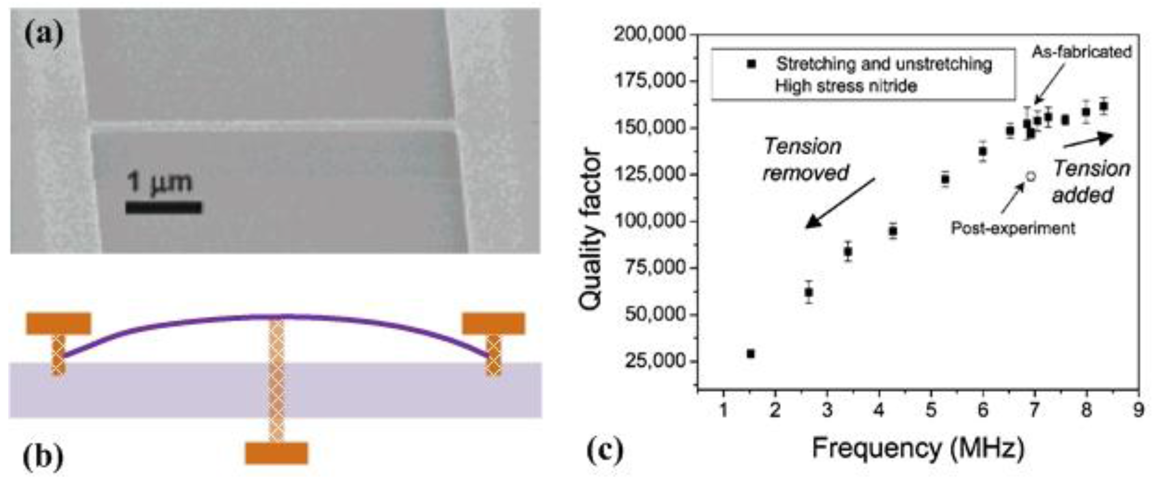
Verbridge
et al. [
125,
200] demonstrated that the tensile stress can be used as a parameter for achieving increased resonant frequency as well as increased quality factor. The direct stretching technique [
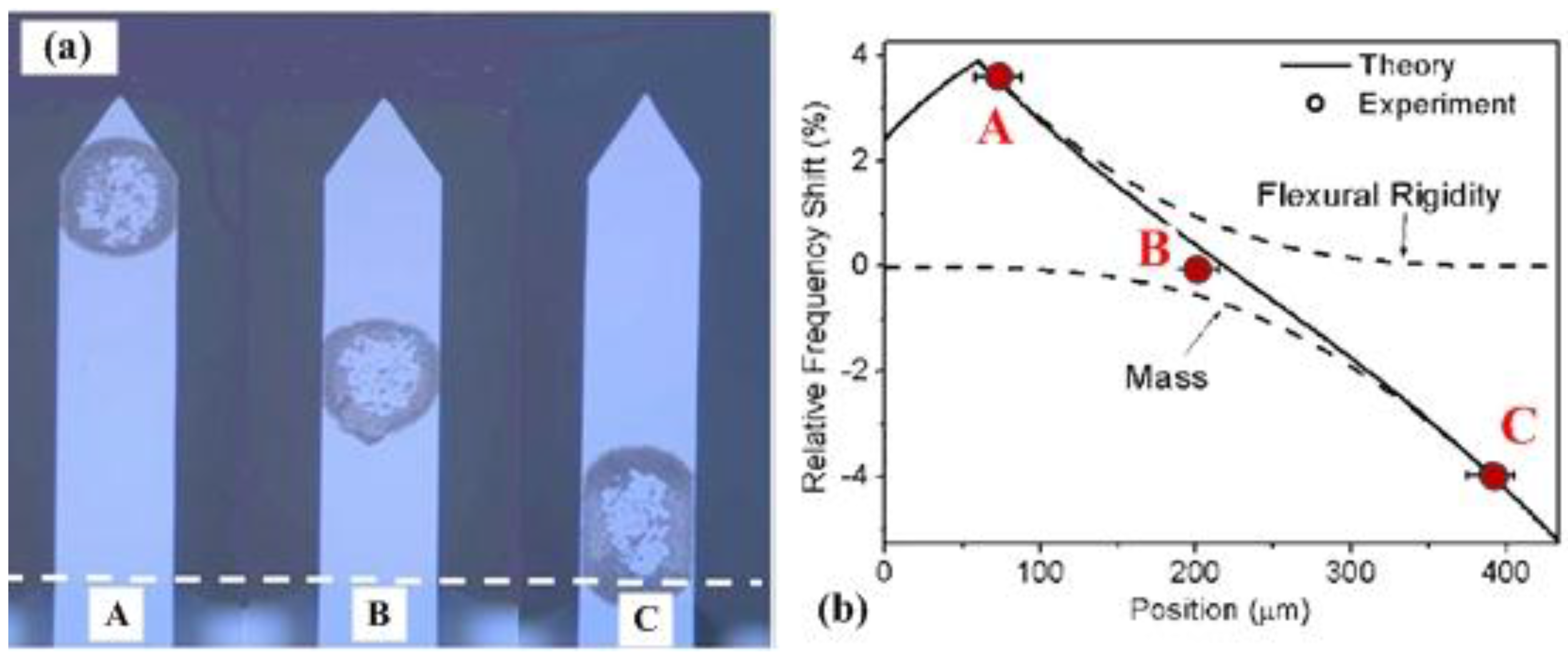
125] was developed to provide the ability to dramatically tune both frequency and quality factor of nanomechanical resonators.
Figure 31 illustrates the effects of stretching on silicon nitride resonators with two different inherent stress values, and the resonant frequency and quality factor can be controlled over a wide range. For the case of 5 μm long device, the resonant frequency and quality factor change from initial values of 14.6 MHz and 1200 to 35.5 MHz and 6700 at the highest stress value, respectively. The tension of this resonator can also be tuned in both directions. It can enable future mechanical resonators to be used as variable frequency references as well as variable band-pass filters. In addition, the composite buckled beam resonator was designed to provide a very high sensitivity platform for sensing [
362,
363] and the compressive pre-stress buckles the beam resonator leading to a strong amplitude–frequency relationship [
364].
Figure 31.
Stress tuning of resonant frequency of the doubly clamped beam resonator reported by Verbridge
et al. [
125]. (
a) Doubly clamped beam resonator; (
b) Schematic digram of the added tensile stress to the resonator; (
c) Experimental results of added stress to tune both resonant frequency and quality factor. Reused with permission from [
125], Copyright 2007, American Chemical Society.
For the case of various boundary conditions, the concept of a local drive force and constraint can allow the cantilever resonator to be tuned over a 300% frequency range [
365], but this technique would be difficult to achieve higher-frequency tuability. The shear-strain-induced tension can also become an alternative method for tuning the CNT resonators [
366,
367].
6.7. Active Electrical Tuning Mechanism
Electrical tuning alters the resonant frequency by adjusting the electrical load [
60,
368]. Circuit-level techniques such as enhanced series tuning have been successfully applied to thin-film piezoelectric-on-silicon resonators [
369] and obtaining up to 1500 ppm of tuning [
370]. For effective series tuning the resonant frequency of resonators, the parasitic pad capacitances of the resonators were counteracted with negative capacitors [
371]. Although electrical tuning is easy to implement and suitable for
in situ tuning, it has low tuning efficiency.
More recently, Norouzpour-Shirazi
et al. [
371] reported an active electrical tuning technique for dynamic tuning of MEMS resonators. The basic tuning mechanism is to generate an electrical displacement signal from the resonator output current, and modify the spring constant linearly in either positive or negative directions. This tuning method has been applied to a piezoelectric AIN-on-Si square resonator (
Figure 32a). As shown in
Figure 32, a tuning feedback loop was used to tune the open-loop resonator frequency response. The resonator was tuned in both positive and negative directions with a linear tuning slope of 830 ppm/V with an overall tuning range of 22 kHz, equivalent to 1550 ppm was measured from active tuning of the closed-loop oscillator.
Figure 32.
An active feedback-based frequency tuning technique for MEMS resonators reported by Norouzpour-Shirazi
et al. [
371]. (
a) SEM of the 4-port AlN-on-Si square resonator; (
b) a feedback loop is used to tune the frequency of the resonator; (
c) the measured tuning and theoretical values using the active tuning method. Reused with permission from [
371], Copyright 2015, IEEE.
8. Concluding Remarks
Micro- and nanomechanical resonators have emerged as robust and ubiquitous devices and serve as important components in advanced technologies ranging from mass sensing and physical, chemical, and biological detections to promise of new materials and observation of quantum phenomena through the change in resonant frequency [
385,
386,
387,
388,
389,
390,
391,
392,
393,
394]. The implementations of tunable resonators with desirable frequencies are widely required and provide more opportunities for both scientific and technological applications.
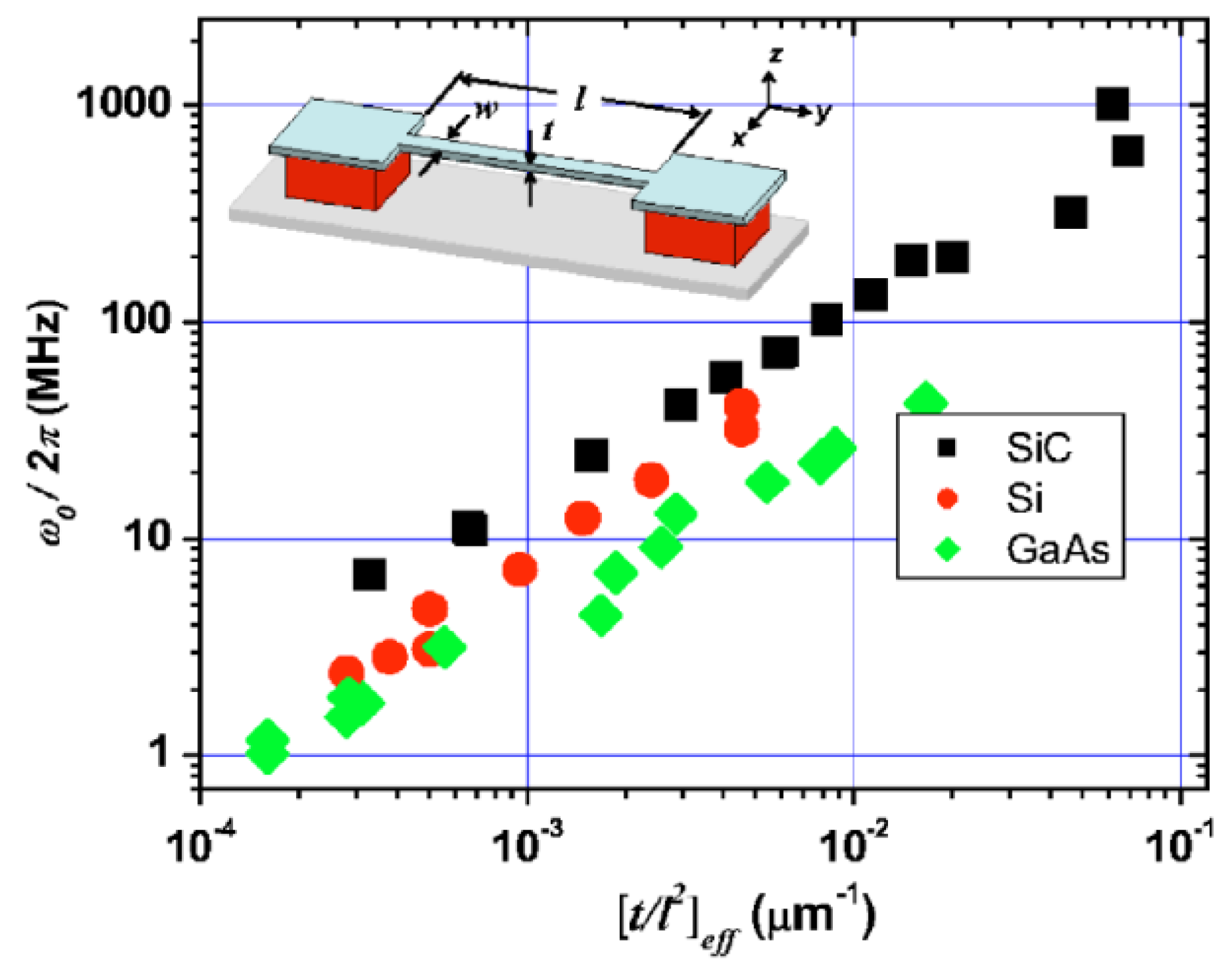
The resonant frequency of a mechanical resonating structure in general scales as
, where
is the scale parameter of the resonator. At microscale, mechanical resonators have their most prominent applications of accurate detection of masses and forces [
395]. When the size of mechanical resonators reduces to the nanoscale, high resonant frequencies can be achieved, but the quality factors are also reduced, which makes the arbitrary reduction of the resonator size challenging. In addition, the size reduction can cause the onset of nonlinearity, decrease the dynamic range and make gigahertz-range transduction more complicated [
148]. Since the micro- and nanomechanical resonators are characterized by a large surface-to-volume ratio, it is demonstrated that the surface effect has an important role on the resonance behaviors as well as the sensing and detection mechanisms, which are very active and on-going research fields. For example, the investigation of the diffusion of adsorbed atoms over the mechanical resonator surface becomes an increasing interest topic [
396,
397]. Rarefied gas flows in the transition regime ubiquitously generated by the nanomechanical resonators causes a significant challenge to the fundamental theoretical analysis and physical explanation of the fluid effect and fluid-structure interactions. The intrinsic stress/strain effect on the micro- and nanomechanical resonators should be considered to determine their mechanical performances and resonant frequencies [
398]. The shifts in resonant frequency are not only caused by the vibration behavior, but also affected by a variety of physical and chemical factors such as the effects of temperature change, surrounding fluid, humidity and adsorption. It is expected that theoretical and experimental approaches for tuning the resonant frequencies can provide a useful tool for optimizing design of micro- and nanomechanical resonators.
For micro- and nanomechanical resonators, control of vibrational energy dissipation is highly desirable. Energy dissipation in mechanical resonators via several mechanisms, including air damping [
399], clamping loss [
400], thermoelastic dissipation (TED) [
401,
402], phonon-tunneling dissipation [
403] and Akhiezer effect [
404], has been widely and deeply studied. For instance, the clamping losses are a widely damping mechanism in nanomechanical resonators and limit the performance of these resonating devices, and the air damping in micromechanical resonators remains an active area of research. Energy dissipation not only has an important impact on the dynamic behavior of mechanical resonators, but also affects the performance of resonator-based devices. As more and more micro- and nanomechanical resonators operate in the nonlinear regime, nonlinear dissipation leads to a limit to the efficiency of dissipation evading methods and techniques [
62,
405]. Recently, strong nonlinear dissipation has been observed in CNT and graphene resonators under tensile strain [
155], in which the nonlinear dissipation is responsible for destroying the hysteresis. Further systematic investigations should focus on the origins and mechanisms of the nonlinear dissipation and predicting the dominant contribution to dissipation in these resonating devices. Moreover, the dissipative processes and nonlinear dissipations contributing to the resonator performance become the active topic of research. In particular, better dynamic response can be obtained by high frequency and low energy dissipation in the resonators and there have tradeoffs between the resonant frequency and quality factor (dissipation) [
274]. Therefore, clearly understanding the energy dissipation mechanisms, further controlling the dissipation, and thus improving the performances of the mechanical resonators, are substantial for implementing their potential applications.
As the geometric dimensions reduce to the microscale and nanoscale, the nonlinearities in most mechanical resonators obviously decrease their frequency stability. And the short-term stability of the resonator is limited by certain noise processes. Although the current frequency stabilization mechanisms provide new strategies for further optimization of micro- and nanomechanical resonators in the nonlinear regime [
406], future investigations should focus on the applications of stabilization methods for high frequency nanomechanical resonators. In addition, nonlinearities such as synchronization and chaotic behavior are very important in micro- and nanomechanical resonators [
15,
24,
58,
407]. It is necessary to have a fundamental insight into the nonlinear vibration behavior, which may be due to the surface effect. Detecting and exciting the vibration and extending the travel range of the resonators [
174,
408] should be also paid more attention. The limit of the dynamic range of the micro- and nanomechanical resonators may come from the thermomechanical fluctuations, quantum noise, adsorption and desorption noises, and extrinsic vibrational and noise sources [
15,
181,
409]. The present linear dynamic range of such resonating devices is useful but severely limited, and even operating in the nonlinear regime. Dynamic control of resonant frequencies and widening the dynamic range of mechanical resonators are the significant and challenging tasks for emerging applications in MEMS/NEMS.
As the first experimental realization of a mechanical resonator in the coupled quantum system was reported by O’Connell
et al. [
410], the mechanical resonators have attracted more and more attentions [
64] due to their the advantages such as superposition and coherent control of the quantum states. The occurrence of nonplanar motions in nanotube and nanowire resonators can be used to broaden interesting applications [
411]. Graphene mechanical resonators can provide the required frequency tunability. The development of suspended micro- and nanochannel resonators will make the measurement with a resolution on the 10 ag scale possible. More significantly, the self-assembled molecular structure reported in [
35] provides a novel way to characterize the mechanical resonators, and will cause challenges to extensively explore a variety of potential applications [
412]. Except for the experimental researches, more theoretical explanations and new computational models should be developed to focus on the underlying mechanisms and make clear understanding of the complex coupling effects on the resonance behavior and performance of the mechanical resonators.
Recent advances of tunable resonators make the fundamental understanding of the frequency tuning mechanisms is important for the future design and optimization of VHF and UHF micro- and nanomechanical resonators. The methodologies of resonant frequency tuning for micro- and nanomechanical resonators contain active and passive methods. One one hand, although previous active tuning approaches such as electrothermal, electrostatic, piezoelectrical, dielectric and magnetomotive techniques are able to tune the resonant frequency of the resonators very precisely, they suffer from either higher power consumption and lower power efficiency or poor nanoscale control over electromechanical coupling effect. Alternative actuation schemes may play an important role in future works as well. On the other hand, the passive methods are preferable in low power consumption applications. Previous passive tuning methods have disadvantageous challenges such as needing expensive equipment and time consuming processes. It is expected that the new passive tuning methods not only have enabled to fabricate micro- and nanomechanical resonators, but also have the capability of conducting efficient and precise frequency tuning, and have not limited to one-direction.
In this review, we have presented an overview of theoretical and experimental approaches which have been used to get insights into the underlying frequency tuning mechanisms of micro- and nanomechanical resonators as well as their wide range of applications. We have briefly described the resonance behavior and frequency tuning principle depending on the change either the stiffness or the mass of the mechanical resonators, and reviewed some tuning structures and latest research progress on the mechanical resonators. We have also discussed some major influencing factors on the implementations of resonators. The efforts to predict, control and apply the resonant frequency shift in the micro- and nanomechanical resonators have been demonstrated. A comprehensive review of research progress on the active and passive frequency tuning methods and techniques for the micro- and nanomechanical resonators has been detailedly addressed. We have additionally provided extensive discussion of the challenges and potential research directions to the tunable micro- and nanomechanical resonators. We hope this review would be helpful for better understanding the importance of frequency tuning in developing the next generation of micro- and nanomechanical resonators.


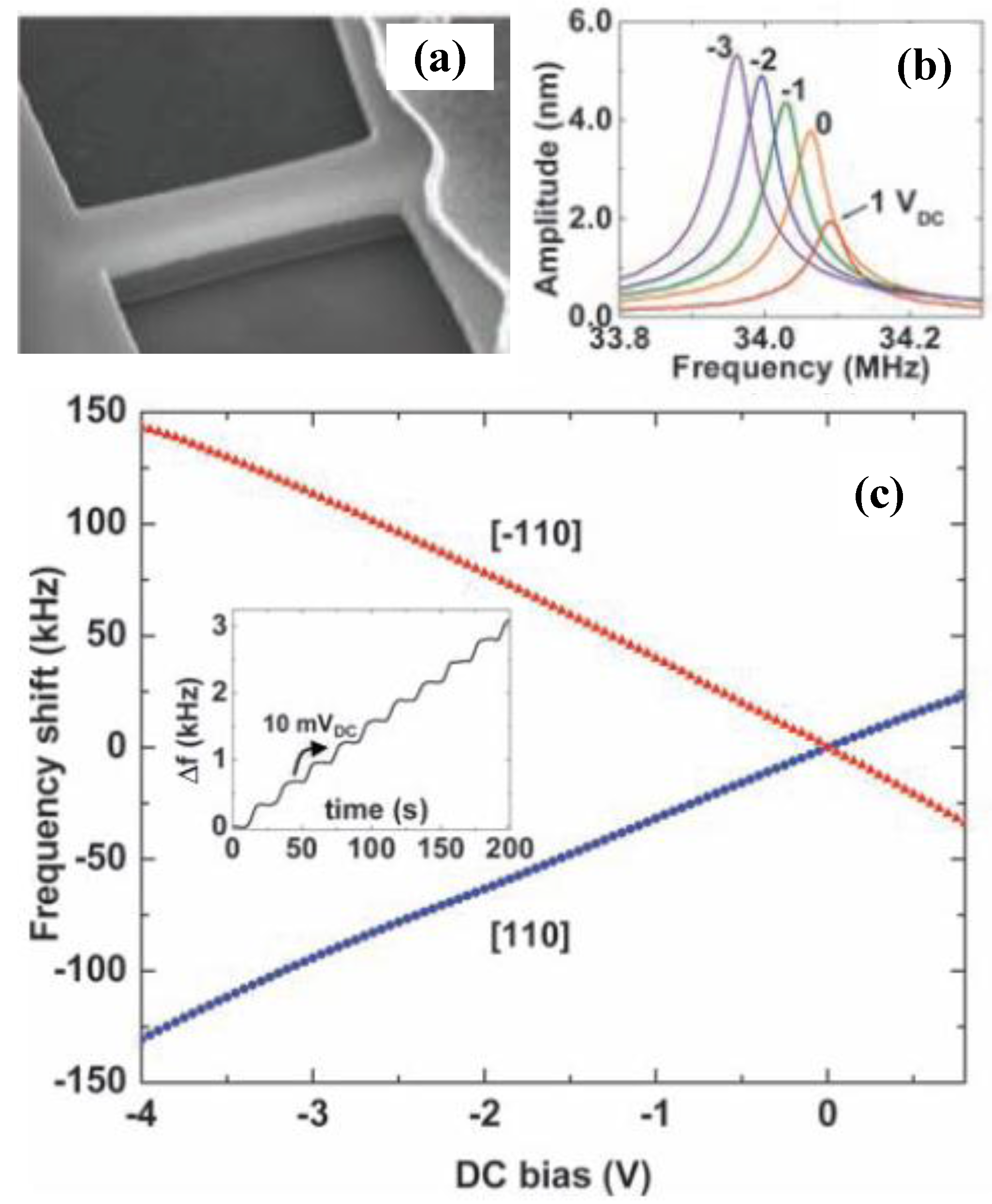
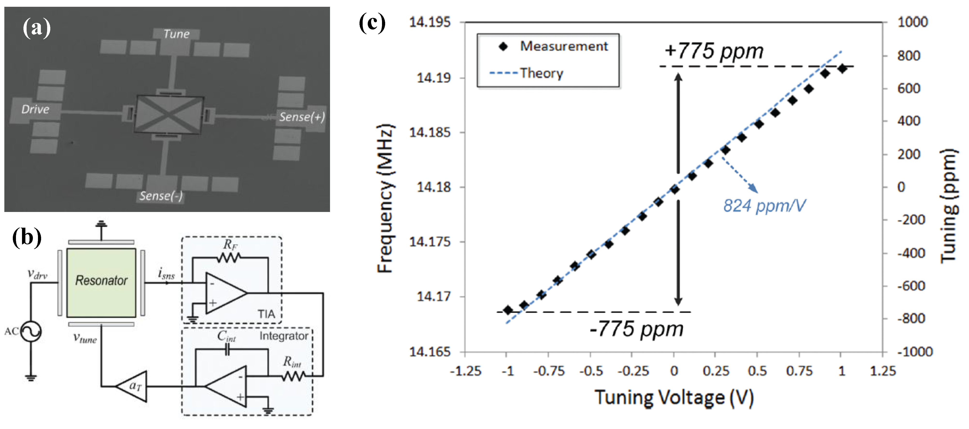
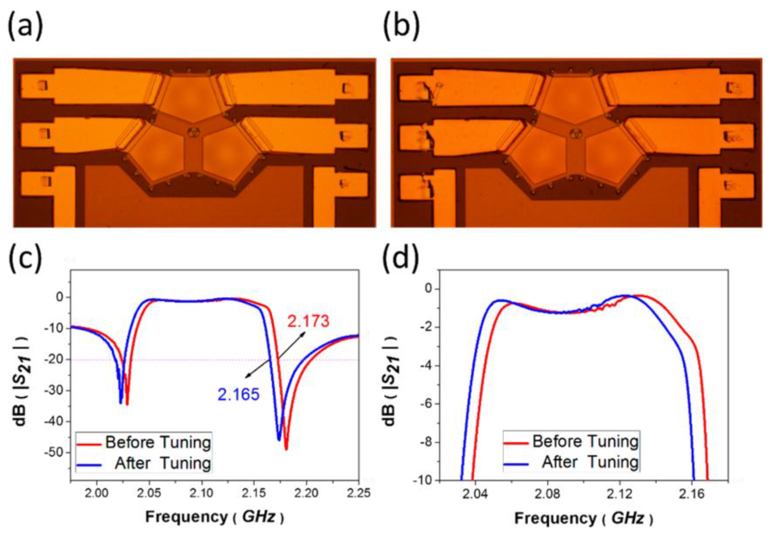
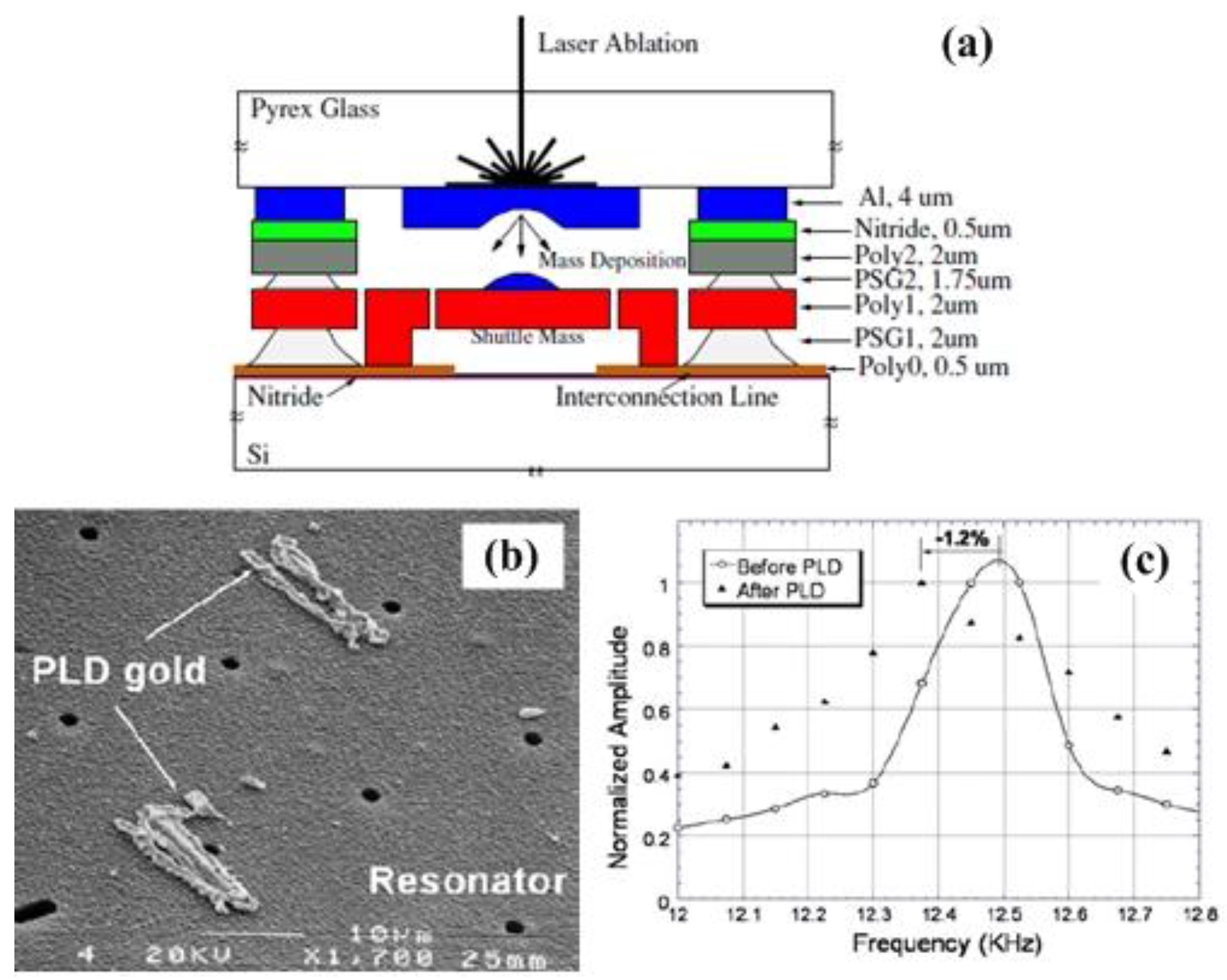