A Subcarrier-Pair Based Resource Allocation Scheme Using Proportional Fairness for Cooperative OFDM-Based Cognitive Radio Networks

Abstract
: The paper presents a joint subcarrier-pair based resource allocation algorithm in order to improve the efficiency and fairness of cooperative multiuser orthogonal frequency division multiplexing (MU-OFDM) cognitive radio (CR) systems. A communication model where one source node communicates with one destination node assisted by one half-duplex decode-and-forward (DF) relay is considered in the paper. An interference-limited environment is considered, with the constraint of transmitted sum-power over all channels and aggregate average interference towards multiple primary users (PUs). The proposed resource allocation algorithm is capable of maximizing both the system transmission efficiency and fairness among secondary users (SUs). Besides, the proposed algorithm can also keep the interference introduced to the PU bands below a threshold. A proportional fairness constraint is used to assure that each SU can achieve a required data rate, with quality of service guarantees. Moreover, we extend the analysis to the scenario where each cooperative SU has no channel state information (CSI) about non-adjacent links. We analyzed the throughput and fairness tradeoff in CR system. A detailed analysis of the performance of the proposed algorithm is presented with the simulation results.1. Introduction
Cognitive radio technology (CR) has been proposed as a relatively new concept for improving the overall utilization of spectrum bands. This promising technology can allow the unlicensed secondary users (SUs, also referred to as CR users or CRUs) to access those frequency bands which are not currently being used by licensed primary users (PUs) in a given geographical area [1,2]. Cooperative communication technology [3] allows network nodes with single antennas to use other network nodes' antennas to transmit data, which can generate a virtual multiple-input multiple-output (MIMO) system. Cooperative spectrum sensing is a viable sensing technique to enhance spectral utilization efficiency of secondary users while ensuring the quality of service (QoS) of primary users [4]. In a CR network, SUs are allowed to transmit over the frequency bands of PUs as long as the resulting aggregate interference is kept below a certain threshold. This threshold is known as interference temperature constraint or interference power constraint [1]. As SUs can design power and subcarrier allocation strategies subject to such interference power constraints, the interference introduced to PUs is effectively controlled. A great deal of resource allocation algorithms and interference control strategies has been proposed for spectrum-sharing CR networks. For example, the optimal power allocation strategies to maximize the transmitted data rate of the secondary user with an effective protection of the primary user were studied in [5,6] for spectrum-sharing CR networks.
Orthogonal frequency division multiplexing (OFDM) is an attractive modulation scheme for users in a CR system due to its flexibility in allocating resources among SUs. Since both SUs and PUs may exist in side-by-side bands, yet have different access technologies, mutual interference is the limiting factor for the performance of both networks. Thus, using of the classical subcarrier allocation and power loading algorithms, such as uniform power but variable rate and water-filling algorithms maximizing the transmission capacity of an OFDM-based conventional wireless network may result in higher mutual interference in the PUs' band. There is only one group of users in such a wireless network, i.e., PUs, for a CR system.
According to the latest literature on resource allocation in cooperative communication [7–17], the relay users in the system do not transmit their own data and merely help other non-relay users transmit data. In some wireless applications such as cellular networks, however, each user has its own data to transmit so that it should allocate its total constrained power and subcarriers properly in transmitting its own data and relaying other users' data [18,19]. Tourki [19] focused on efficiency issues by studying how to maximize the total transmitted data rate in non-orthogonal amplify-and-forward (AF) cooperative scheme, which ignores the fairness among the cooperative users. According to [20,21], equal power allocation (EPA) among subcarriers was proposed to separate the user selection from the power of subcarrier. With EPA, the EPA-PRG (proportional rate greedy) [22] algorithm is proposed to maximize the system throughput while keeping the fairness. However, cooperative transmission technology isn't applied in this algorithm. In [23], a linear water-filling scheme (LWF-PI) was proposed. This algorithm maximized the overall transmitted data rate of the CR system while keeping the interference introduced to the PU bands below a threshold. However, the fairness among users was ignored. Chandrashekar et al. [24] proposed an algorithm which is capable of maximizing the total transmitted data rate and achieving a high proportional fairness index. However, this algorithm cannot be applied to the CR network where we must adjust the interference introduced to the PU bands below a threshold. Tan [25] proposed a joint subcarrier and power algorithm based on Blotto games. This algorithm can achieve a good trade-off performance between fairness and efficiency in OFDMA-based cognitive radio network (CRN), but it cannot obtain the effectiveness of multiuser diversity for the SUs without ability to generate a virtual MIMO system.
A novel scheme was presented in [26] for the allocation of subcarriers, rates, and power in orthogonal frequency-division multiple-access (OFDMA) networks. The resource-allocation problem was solved by decomposing it into a hierarchy of sub-problems. A joint subcarrier and power allocation algorithm was presented in [27] for cooperative MU-OFDM CR systems. In [28], a survey of resource allocation and scheduling schemes in OFDMA wireless networks was presented. Nader et al. in [29] considered the practical case in which only partial CSI for the wireless channel between the secondary base station and SUs is available at the secondary base station. They formulated the resource allocation problem in the secondary network as an optimization problem in which the objective was to maximize the weighted sum rate of the secondary users. A novel sub-channel and transmission power allocation scheme was proposed in [30] for multi-cell OFDMA networks with CR functionality. Tianxiang et al. in [31] discussed optimization over the relay assignment, subcarrier allocation, per node power control, and heterogeneous quality-of-service (QoS) provisioning. Sabit et al. in [32] investigated the performance of an OFDM-based CR spectrum sharing communication system that assumed random allocation and absence of the PU channel occupation information. Hong Xu et al. in [33] formulated a unifying optimization framework based on Nash bargaining solutions to fairly and efficiently allocate resources between primary and secondary networks, in both decentralized and centralized settings. As the optimal resource allocation scheme was highly complex, G. B. et al. [34] proposed a low complexity suboptimal subcarrier and power allocation scheme. They also proposed a suboptimal subcarrier allocation scheme that can guarantee a certain level of fairness among CR users. Naeem et al. introduced in [35] a hybrid heuristic algorithm for the relay assignment and power allocation problem which is a non-convex mixed-integer non-linear optimization problem, and this problem is generally non-deterministic polynomial-time (NP)-hard.
In this paper, a joint subcarrier-pair based resource allocation algorithm in order to improve both efficiency and fairness index is presented first. The definition of fairness is borrowed from the networking literature. In contrast with [36], where large channel fluctuations are intentionally created with “dumb” antennas for long-term proportional fairness resource allocation, this paper proposes a subcarrier-pair based resource allocation algorithm to maintain proportional rates among SUs for each channel realization, which ensures the rates of different SUs to be proportional in any time scale of interest. By formulating the resource allocation and pairing problem in this way, it will be shown that a high transmitted data rate for all SUs (even those with poor channel gains) can be achieved with low computational complexity. Moreover, we extend the analysis to the case in which each SU can only have access to CSI of its adjacent links. This is a more realistic scenario when network nodes are mobile and the timely CSI cannot be exchanged between cooperative users. Consequently, each user can only have access to statistical CSI of non-adjacent links. It is shown that the system performance deteriorates due to limited CSI but still outperforms that of equal power allocation scheme. The key contributions of this work are:
It is considered that SUs need to transmit their own data directly to the destination, and in the next phase they also help their partner forward the data received in previous phase to the destination. Simulation results show that in the same situations the system transmitted data rate by proposed algorithm is the highest than that by LWF-PI algorithm [23], EPA algorithm [21] and the Optimal Scheme [37].
The proposed subcarrier-pair based resource allocation algorithm ensures the rates of different SUs to be proportional in any time scale of interest, simulation results shown that a high transmitted data rate for all SUs (even those with poor channel gains) can be achieved.
It is considered that SU has no CSI about non-adjacent link. In this case, we take full advantage of the statistical information of the non-adjacent links.
Notation: In this paper, a variable with “underline” ■̲ denotes the temporary optimal values within each iteration process, the “double underline” ■̳ denotes the optimal value, and the “bar” ■̄ denotes the statistical average value. E (■) denotes the expectation operator, and denotes the optimal value when only partial CSI can be obtained by SUs.
2. System Model and Problem Formulation
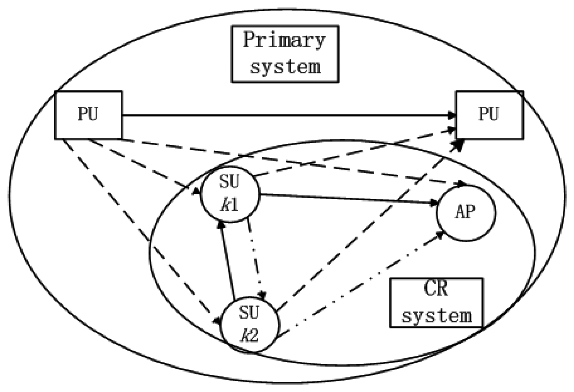
We consider a hybrid network consisting of a primary network (PRN) and a cognitive radio network (CRN) as shown in Figure 1. The CRN consists of a CR access point (AP) and 2K SUs. The PRN and CRN co-exist within the same geographical area. The access mechanism/modulation format in SUs' band is OFDM. Our focus is mainly on the uplink radio resource allocation in the CRN. The SUs are trying to find the opportunity to access to the AP.
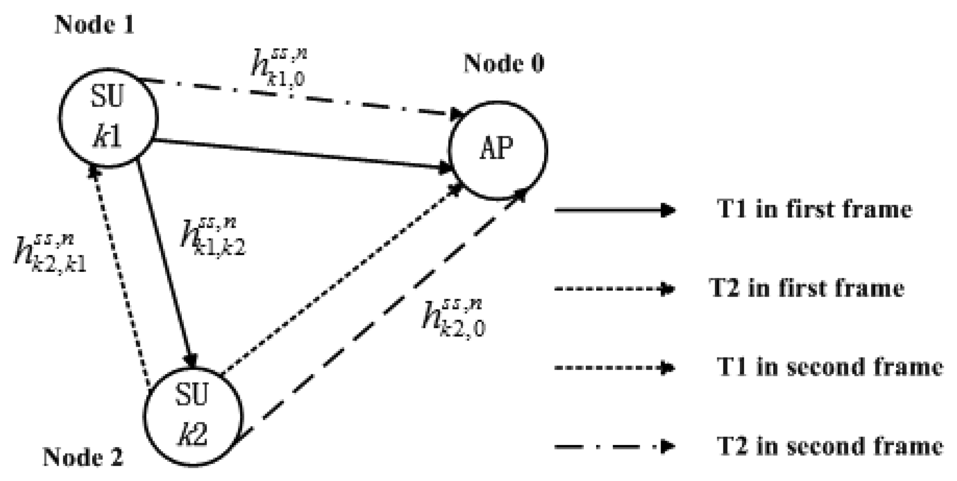
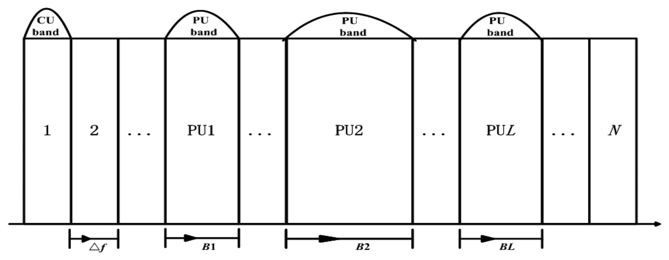
According to [37,38], we also consider that the frequency bands of bandwidth B1, B2, …, BL which have been occupied by L PUs are sensed by the CR system and known to SU transmitters. Every two SUs form a cooperative partner and they are relay node for each other. As shown in Figure 2, the kth (1 ≤ k ≤ K) cooperative partner consists of two SU transmitters, k1 and k2. As is assumed in [23,37,38], we consider the same side-by-side CR radio access model. The unoccupied bandwidth sensed by SUs for opportunistic spectrum access is located on each side of L PU bands as shown in Figure 3. The available bandwidth for CR transmission is divided into N subcarriers based on OFDM system. It is considered that the access mechanism/modulation format in PUs' band is not known to the CR system and the bandwidth for each CR subcarriers is Δf Hz. Some symbols are shown in Table 1.
In general, there are three instantaneous fading gains in the uplink transmission scenario shown in Figure 1:
- (1)
The gains between the SU's transmitter and SU's receiver or AP for the nth subcarrier denoted as , , respectively.
- (2)
The gains between the SU's transmitter and lth PU's receiver, denoted as .
- (3)
The gains between the lth PU's transmitter and the SU's receiver or AP, denoted as , , respectively.
The channel gains are modeled as independent zero-mean complex Gaussian random variables, where ki denotes the ith SU in kth cooperation partner and pl denotes the lth PU band. According to [39], it is considered that these instantaneous fading gains are perfectly known at the SU's transmitter. Specifically, we assume that the SU's receiver can estimate channel gains and and report to the CR transmitter. In Section 3.2, we will study the case where the instantaneous fading gains of the non-adjacent links are not perfectly known at the SU transmitter but the statistical information of the non-adjacent links are known at the SU transmitter. Moreover, it is assumed that primary receiver can estimate the channel which is reported to the SU transmitter through a common control channel.
2.1. Cooperative Transmission among SUs
The scenario of a three-node DF diversity model is considered, where one source communicates with one destination assisted by one half-duplex relay, as shown in Figure 2. One transmission period is divided into two consecutive frames. Communication takes place in two phases (listening phase T1 and relaying phase T2, the definition is according to the working state of relay user) for each frame. The power allocation scheme for kth cooperative partner on subcarrier n is shown in Table 2. The source node broadcasts its signal to relay and AP in T1, whereas the relay and AP listen. The relay decodes the signal and forwards it to AP in T2. It is denoted that the subcarrier n in T1 is pairing with subcarrier SP1(n) in T2 for first frame, and pairing with subcarrier SP2(n) for second frame. In the first frame, k2th SU receives data in this time slot while k1th SU transmits a symbol xk1(t) with power level on nth subcarrier in T1. The symbol is received by node 0 (AP) and overheard by k2th SU as:
During this interval, the k2th SU decodes its overheard signal as and transmits it to the AP on SP1(n) subcarrier in T2 with the power level . Then the AP receives the signal as:
In the second frame, the roles of k1th SU and k2th SU are reversed. Similarly, k2th SU transmits a symbol xk2 (t) with power level on the nth subcarrier in T1. The symbol is received by node 0 (AP) and overheard by k1th SU as:
In T2 of second frame, the AP node receives the noisy signal which is relayed by k1th SU with the power level , i.e.:
2.2. Mutual Interference between PU Bands and CR Users
In the MU-OFDM CR system, due to the coexistence of PUs and SUs in side by side bands, it is necessary to consider the mutual interference between PUs and SUs. There are two types of interference in the system. One is introduced by the PUs into the SUs band, and the other is introduced by the SUs into the PUs' band. In what follows, we provide brief description and mathematical models for interference between SUs and PUs.
2.2.1. The Interference Introduced into PUs by SUs
CR interference is introduced into the PU spectrum by CR out-of-band (OOB) emissions. OOB emissions arise as a result of transmit pulse shaping such that a portion of the CR radiated power in a vacant subcarrier is leaked into neighboring bands occupied by the PUs. According to [23], the interference factor which is the integration of the power density spectrum of the nth subcarrier across the lth PU band, and can be written as:
2.2.2. The Interference Introduced into SUs by PUs
The interference introduced into kith SU and AP node transmitting in nth subcarrier by lth PU can be denoted as , , respectively. According to [37], the interference value , can be written as:
According to [40], using a relay is advantageous when:
3. Optimization Problem Formulation
In this section, we analyze the joint optimization of subcarrier-pair based resource allocation algorithm for OFDM-DF based on full CSI and partial CSI, respectively. We are interested in how each SU allocates its power properly across its own data and its relayed data so as to maximize the system transmitted data rate while maintaining reasonable fairness between SUs. The optimization problem is formulated firstly and then solved in the dual domain. It is assumed that the PUs have a constant-rate, constant-power transmission, while the SUs are capable to adjust transmit power over different fading states based on the CSI of the CR network. We study a type of constraint imposed over the secondary transmission to protect the PUs by limiting the interference introduced to the PUs below a threshold.
3.1. Resource Allocation and Subcarrier Pairing Scheme Based on the OFDM-DF
The CR AP combines the received signals from the source node in T1 and the relay node in T2 through the maximal ratio combining. The transmit power is adjusted in each SU's transmitter. According to [27] and [41], when the link of source node->relay node transmission is successful for entire DF process, the transmission rate of k1th SU and k2th SU at n subcarrier in relaying mode, which is connected via the Shannon capacity formula, can be shown as and , respectively:
Let , i = 1,2 where i denotes the ith frame. This formula means that the average of the transmit power of the source node and that of the relay node is constrained to be , which is the allocated power on subcarrier n at the source node for direct transmission. According to [42], the solution to this problem is the transmitted data rate and it is maximized when:
Let:
Together with , i = 1, 2 we can obtain that:
Denote , as the equivalent channel gain given by:
By now, we can unify the transmitted data rate as:
The proportional fairness is used as the optimized objective to develop subcarrier-pair based resource allocation algorithm in order to maintain a balance between system efficiency and fairness. According to [43,44] and the theorem in [45], we can readily deduce that there exists one unique proportionally fair allocation which can be attained by maximizing the objective function over the feasible set, where ωk is the weighting factor to make the K cooperative partners achieve the desirable transmitted data rate. Besides, we should keep the instantaneous interference introduced to the PUs below a certain threshold. The constraints include the aspects of satisfying the maximum power and interference constraints as well as the minimum rate requirements. Therefore, the resource allocation problem can be formulated mathematically as given in Equation (14). Constraint C1 corresponds to the subcarrier allocation constraint that each subcarrier n only can be allocated to one cooperative partner. C2 and C3 define that the sum of all the transmission powers of a particular SU on different subcarriers can't be greater than the maximum allowed limit for that particular SU. C4 ensures the cumulative interference from all SUs and through all subcarriers on a particular PU should not be greater than the interference limit set. C5 ensure that each SU can obtain the minimum rate requirements. This constraint precludes the possibility of multiple SUs simultaneously transmitting at the same subcarrier:
The optimal solution to Equation (14) can be found by performing an exhaustive search with computational complexity O(KNZ) [46], where KN is the number of possible subcarrier allocations and Z is the complexity of a power allocation algorithm for each subcarrier allocation. To reduce the exponential computational complexity, a suboptimum resource allocation algorithm with less computational complexity is developed in the following. The dual decomposition approach is used to solve the problem. The dual problem of Equation (14) can be formulated as:
The Equation (15) can be decomposed into two layers of sub-problems. In the lower layer, we can get K sub-problems:
We suppose that Γk is the maximum value of the objective function in the lower layer. The master problem in the upper layer could be expressed as:
Since a dual function is always optimized by first optimizing some variables and then optimizing the remaining ones. We define a subcarrier pairing parameter βn,m ∈ {0,1} that takes 1 if the nth subcarrier in T1 is pairing to mth subcarrier in T2 and 0 otherwise. We first optimize the primal variables with the assumption that dual variables are given. The resource allocation and subcarrier pairing process can be divided into four stages:
- (a)
Allocating the optimal power factor for SUs. and imply the power used for self-data transmission, respectively and imply the power used for partner-data transmission, respectively.
Allocating the optimal set of subcarriers Ωk for kth cooperation partner, i.e., obtaining the optimal subcarrier allocation factor ρkn.
Optimal pairing process for the subcarriers which are allocated to Ωk, i.e., allocating the optimal subcarrier pairing factor βn,m.
After the temporary optimal primal variables have been obtained in each iteration process, we would find the temporary optimal dual variables , which can minimize the objective function H(P) as shown in Equation (18).
3.1.1. Power Allocation Algorithm
Let , if we make ρkn = 1, the power allocation can be determined in a water-filling fashion. Taking derivatives of with respect to , .
Taking derivatives of with respect to , , and according to Equation (19), we can get:
Together with the constraint , , the temporary optimal solution can be obtained:
The temporary SU's transmit power can be obtained for the given dual variables:
3.1.2. Subcarrier Allocation Algorithm
The subcarrier allocation constraint is that each subcarrier is allocated to no more than one SU cooperative partner, which prevents mutual interference among SUs. According to Section 3.1.1, we can get a temporary optimum power . We substitute this temporary optimum power vector into the objective function and the objective function to obtain the temporary max value and , respectively. Taking account of resource fairness, we can formulate the optimization problem of subcarrier allocation as:
- (1)
Initialization
- (i)
Make ρkn = 0, Ωk = Ø, ∀k, n
- (2)
For n = 1 to N
- (i)
For k = 1 to K
- a)
Make ρkn = 1
- b)
Assign Vnk = h(ρ) according to Equation (23)
- c)
Make ρkn = 0.
- (ii)
Assign
- (iii)
Assign ρk*n = 1, Ωk* = Ωk* ∪ {n}, ρkn= 0, ∀k ≠ k*
According to Section 3.1.2, we can obtain a temporary subcarrier allocation vector for the given dual variables.
3.1.3. Subcarrier Pairing Algorithm
The pairing constraint is that each subcarrier m in listening phase only pairs with at most one subcarrier n in the relaying phase. We assume that the pairing for deferent frames is not the same. The pairing process of the subcarrier allocated to kth cooperation partner can be expressed as:
Constraints C6, C8 and C10 correspond to the pairing constraint that each subcarrier n in listening phase only pairs with one subcarrier m in the relaying phase in the first frame. Constraint C7, C9 and C11 correspond to the pairing constraint that each subcarrier n in listening phase only pairs with one subcarrier m' in the relaying phase for the second frame. We can obtain the temporary optimal m, m′ for any n as:
That is:
The subcarrier pairing scheme can be shown as following:
For k = 1 to K
- (a)
Δ = Ωk, Δ′ = Ωk, βn,m = 0, βn,m′ = 0, ∀ n,m,m′ ∈ Ωk
- (b)
While Δ ≠ Ø, Δ′ ≠ Ø
- (i)
n ∈ Δ, n′ ∈ Δ′
- (ii)
Find m ∈ Δ, m′ ∈ Δ′ satisfying , , ∀l ∈ Δ, ∀l' ∈ Δ′
- (iii)
Assign
SP1 (n) = m, βn,m = 1, Δ = Δ − {n} − {m}
SP1 (n′) = m′, βn′,m′ = 1, Δ′ = Δ′ − {n′ } − {m′ }
Through Section 3.1.3, we can obtain a temporary optimal subcarrier pairing vector , , 1 ≤ {n, m, m′ } ≤ N for the given dual variables.
3.1.4. Optimizing the Dual Variables
The optimal values of dual variables can be achieved iteratively by the sub-gradient method as follows:
Within each iteration process, the power allocation vectors can be updated respectively by Equation (22), the subcarrier allocation vectors can be updated respectively by subcarrier allocation algorithm shown in Section 3.1.2, the subcarrier pairing vectors can be updated respectively by subcarrier pairing algorithm which is shown in Section 3.1.3, with the updated value . Therefore, the dual variable λi will converge to the dual optimum λ̳ as i → ∞ and the temporary primal optimum variable will also converge to the primal optimum value after several iterations, i.e., temporary vector will converge to optimal vector , temporary optimal vector will converge to the optimal vector , temporary vector , will converge to the optimal vector , .
3.2. Resource Allocation with Partial CSI
If full CSI can be achieved at the k1th and k2th (1 ≤ k ≤ K) SU transmitter, the optimal subcarrier allocation vector ρ̳, subcarrier pairing vector , , the power allocation vector can be determined simply by the proposed algorithm which is shown in Section 3.1. However, the practical case in which only partial CSI of the wireless channel between the secondary base station and SUs is available have to be considered. The CSI of non-adjacent link may be undesirable and even unavailable when the SUs are mobile. In this section, we investigate the optimal resource allocation in SU cooperation network with partial CSI at each transmitter. Specifically, the kith SU transmitter has full CSI of its adjacent links , but only statistical CSI of non-adjacent link . We assume that the SUs can know , , i.e., are still available at SU transmitter, and the link between cooperative users is symmetric for simplicity, i.e., .
Under these assumptions and according to [47], the objective function:
In order to seek the optimal power allocation solution, we derive the explicit expressions for and described as:
Let , i=1,2, where dki,0 denotes the distance between the kith SU and the AP, v is the path-loss exponent, xki,0, (i = 1,2) is the normalized complex Gaussian random variable distributed as CN (0, 1), then at high signal-to-noise ratio (SNR):
Proof: It is sufficient to show , and can be derived in exactly the same way, then
The third equality holds since we assume each transmission block is long enough to undergo different channel realizations as argued in [48]. Next, let:
Then using the assumption that SNR is high, we readily obtain Equation (32). This completes the proof.
We can use the resource allocation and subcarrier pairing algorithm which is proposed in Section 3.1 to solve the corresponding optimization Equation (14) once again. When partial CSI can be achieved by SUs, the optimal subcarrier allocation vector , subcarrier pairing vector , and optimal power allocation vector , can be obtained. According to Equation (11), we can get
Then we also can get:
Intuitively, the system performance would be degraded due to limited CSI though this scheme which does not require each cooperative node to have full CSI of nonadjacent link, as verified in the numerical simulation.
3.3. Comparison with Classical Resource Allocation Algorithms
Several existing schemes are compared with the proposed subcarrier-pair based resource allocation algorithm in terms of the system transmitted rate and fairness, respectively. These existing schemes include the following:
LWF-PI-without-SP: The subcarrier is allocated according to the channel gain. The messages transmitted on subcarrier m at the source node will be retransmitted on the same subcarrier m at the relay node. The power is allocated according to LWF-PI algorithm [23] on each subcarrier.
EPA-without-SP: The subcarrier is allocated according to the channel gain. The messages transmitted on subcarrier m at the source node will be retransmitted on the same subcarrier m at the relay node. The power is allocated equally on each subcarrier.
LWF-PI-with-SP: The subcarrier is allocated according to the channel gain. The messages transmitted on subcarrier m at the source node will be retransmitted on subcarrier n, which is selected by proposed subcarrier pairing algorithm, at the relay node. The power is allocated according to LWF-PI algorithm [23] on each subcarrier.
EPA-with-SP: The subcarrier is allocated according to the channel gain. The messages transmitted on subcarrier m at the source node will be retransmitted on subcarrier n, which is selected by proposed subcarrier pairing algorithm at the relay node. The power is allocated equally on each subcarrier.
Optimal-Scheme-with-SP: The subcarrier is allocated according to the channel gain. The messages transmitted on subcarrier m at the source node will be retransmitted on subcarrier n, which is selected by proposed subcarrier pairing algorithm at the relay node. The power is allocated according to Optimal Scheme [37] on each subcarrier.
Partial CSI: the difference between the previous five algorithms and Partial CSI scheme is that the SU has only imperfect CSI of non-adjacent link under partial CSI scheme. In this case, the objective function is formulated by statistical methods.
4. Simulation Results
We have studied asymmetric or linear network with all SUs of kth cooperative partner located in the same line. Specifically, k1th SU and the destination AP are fixed at (0, 0), (1, 0) respectively, and k2th SU is located at (d, 0), 0 ≤ d ≤ 1, without loss of generality. The results for path loss exponent ν = 2 are presented and all channels are modeled as Rayleigh flat fading with AWGN. Some simulation parameters are shown in Table 3.
Simulation results are presented in this section to verify the performance of the proposed subcarrier-pair based resource allocation algorithm. In our simulations, the CVX, a package for specifying and solving convex programs, is used to solve formulated optimization resource allocation problems.
The channel gains , , , , used in this paper are assumed to be Rayleigh fading, since the channel fading gains for different realizations of channel gain can be different, an average transmission capacity of 10,000 independent simulation runs is considered. And individual fairness index is defined as [46]:
The fairness ranges between 0 and 1. The higher the value fairness is, the more fair the throughput distribution among SUs is.
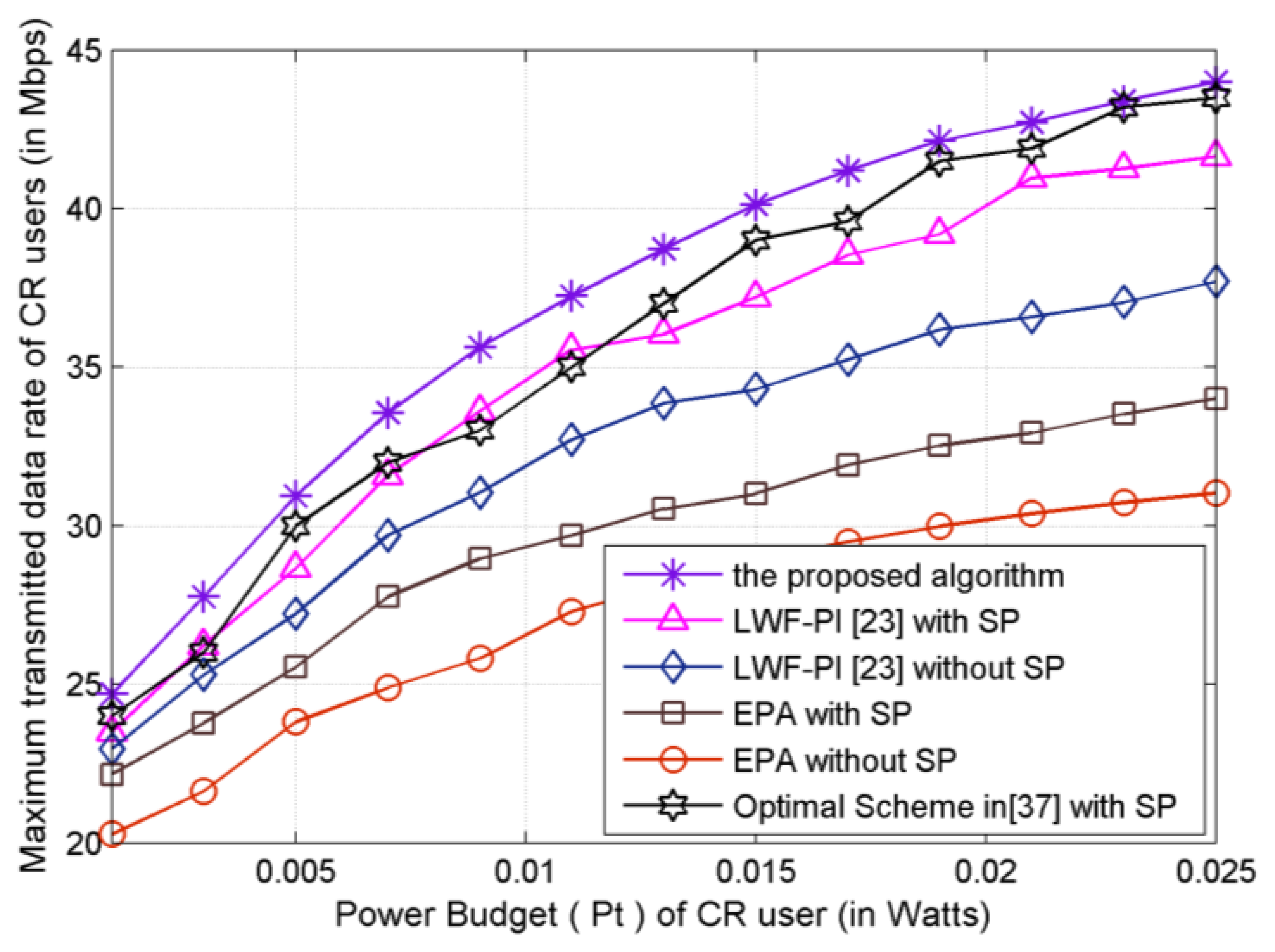
4.1. The System Transmitted Data Rate Obtained under Resource Allocation Algorithms
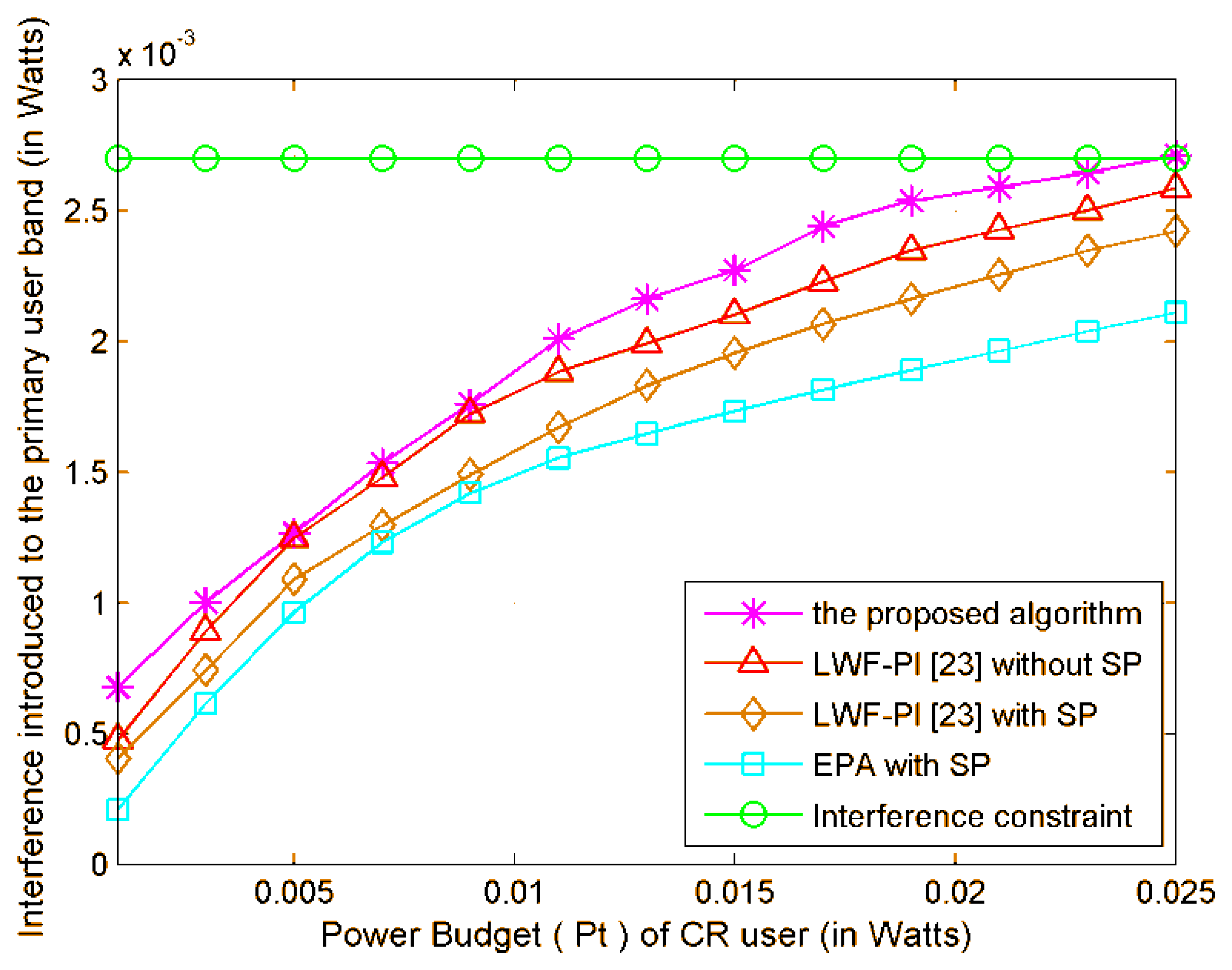
As shown in Figure 4, the achievable maximum CR system transmitted data rate is plotted versus the power budget Pt. The upper curve denotes the transmitted data rate by proposed subcarrier-pair based resource allocation algorithm with full CSI. It can be noted that the proposed subcarrier-pair based resource allocation algorithm achieves the highest transmitted data rate under a given total power constraint. The transmitted data rate achieved using the proposed algorithm is the highest among that using LWF-PI-with-SP, Optimal-Scheme-with-SP algorithm, LWF-PI-without-SP algorithm and EPA algorithm. The main reason is that the proposed algorithms can make full use of the entire available interference threshold, while the LWF-PI algorithms can only guarantee that the total interference is under the interference threshold as shown in Figure 5. We observe that only the proposed algorithm outperforms the compared existing resource allocation algorithms. Therefore, we can conclude that the proposed subcarrier-pair based resource allocation algorithm makes valuable contribution to system transmitted data rate.
4.2. The Fairness Index Obtained under Resource Allocation Algorithms
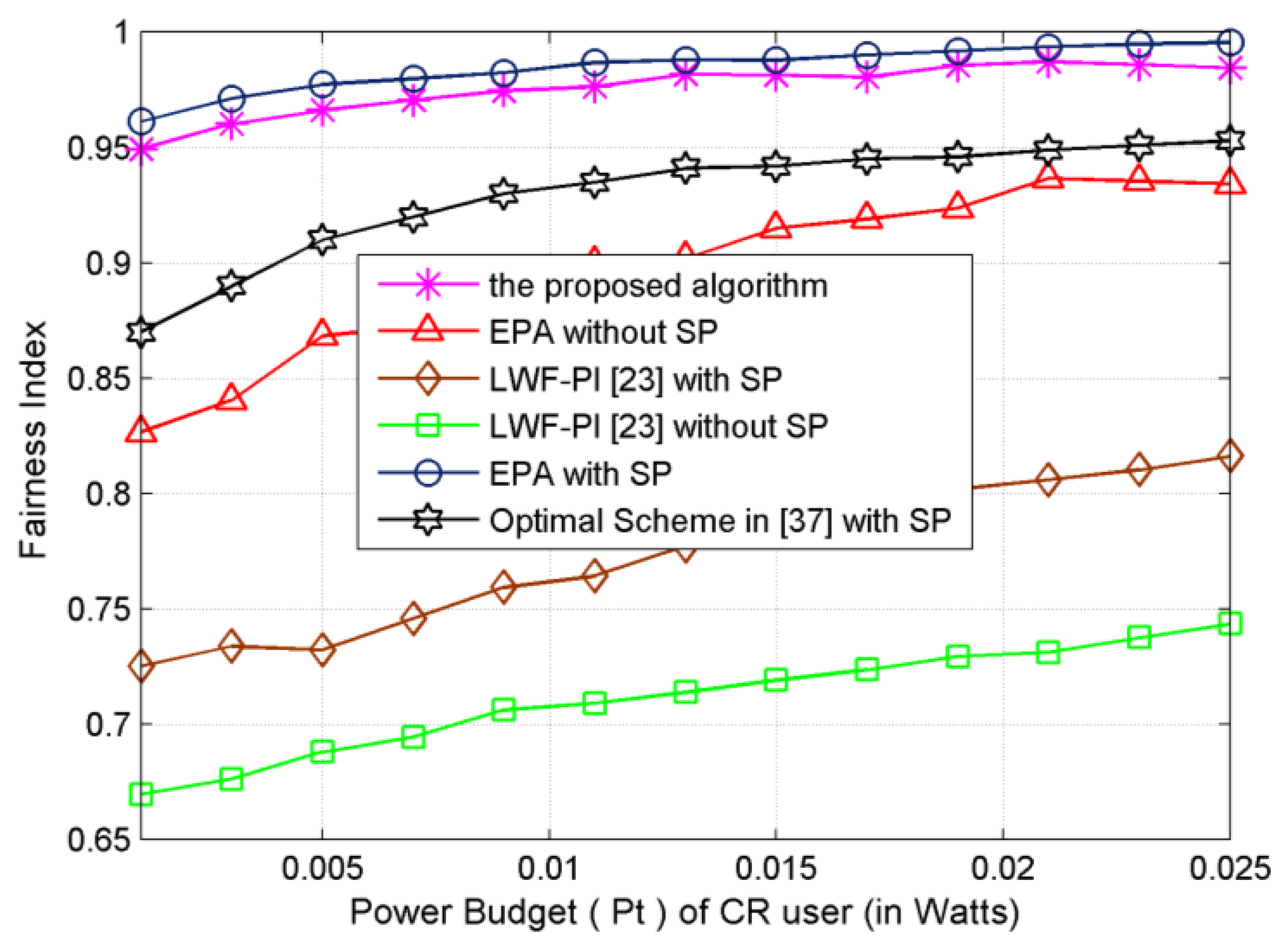
Both the proposed resource allocation algorithm and EPA-with-SP algorithm exhibit the best fairness performance and LWF-PI-without-SP algorithm shows the least fairness as shown in Figure 6. Moreover, the fairness loss of EPA-with-SP allocation algorithm compared to the proposed subcarrier-pair based resource allocation algorithm is acceptable. In the LWF-PI-without-SP algorithm, LWF-PI-with-SP algorithm and Optimal-Scheme-with-SP algorithm, most power and subcarrier will be assigned to SUs with good channel conditions to improve system efficiency. Unlike the proposed subcarrier-pair based resource allocation algorithm and EPA schemes, these two schemes achieve significant performance improvement to ensure fairness among SUs. The fairness obtained by EPA-with-SP effectively approaches to 0.98. Due to multiuser diversity, the fairness attained by the proposed algorithm is above 0.95, while the achievable system transmitted data rate is higher than that of LWF-PI and EPA-without-SP algorithms.
4.3. The Transmitted Data Rate of Each SU for the Resource Allocation Schemes
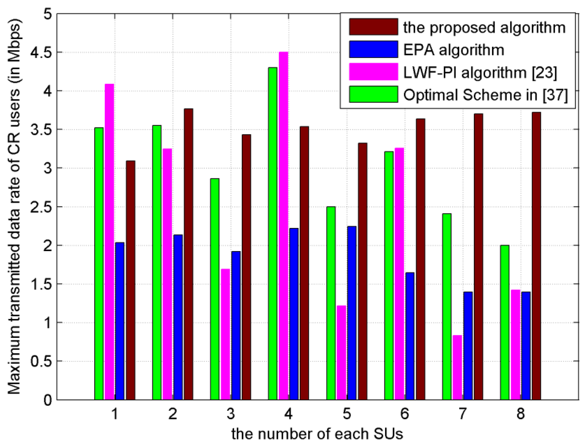
As shown in Figure 7, the achievable transmitted data rate of each SU is plotted. The transmitted data rate of each SU, under the proposed subcarrier-pair based resource allocation algorithm, is the most balanced and stable among EPA, LWF-PI and Optimal Scheme [37]. Especially under the LWF-PI algorithm and Optimal Scheme [37], some SUs with bad channel conditions have lower transmitted data rates, which would result in unsuccessful communication with destination node. We can conclude that the proposed subcarrier-pair based resource allocation algorithm makes valuable contribution to balance transmitted data rates among SUs.
4.4. The System Transmitted Data Rate Obtained under Full CSI and Partial CSI
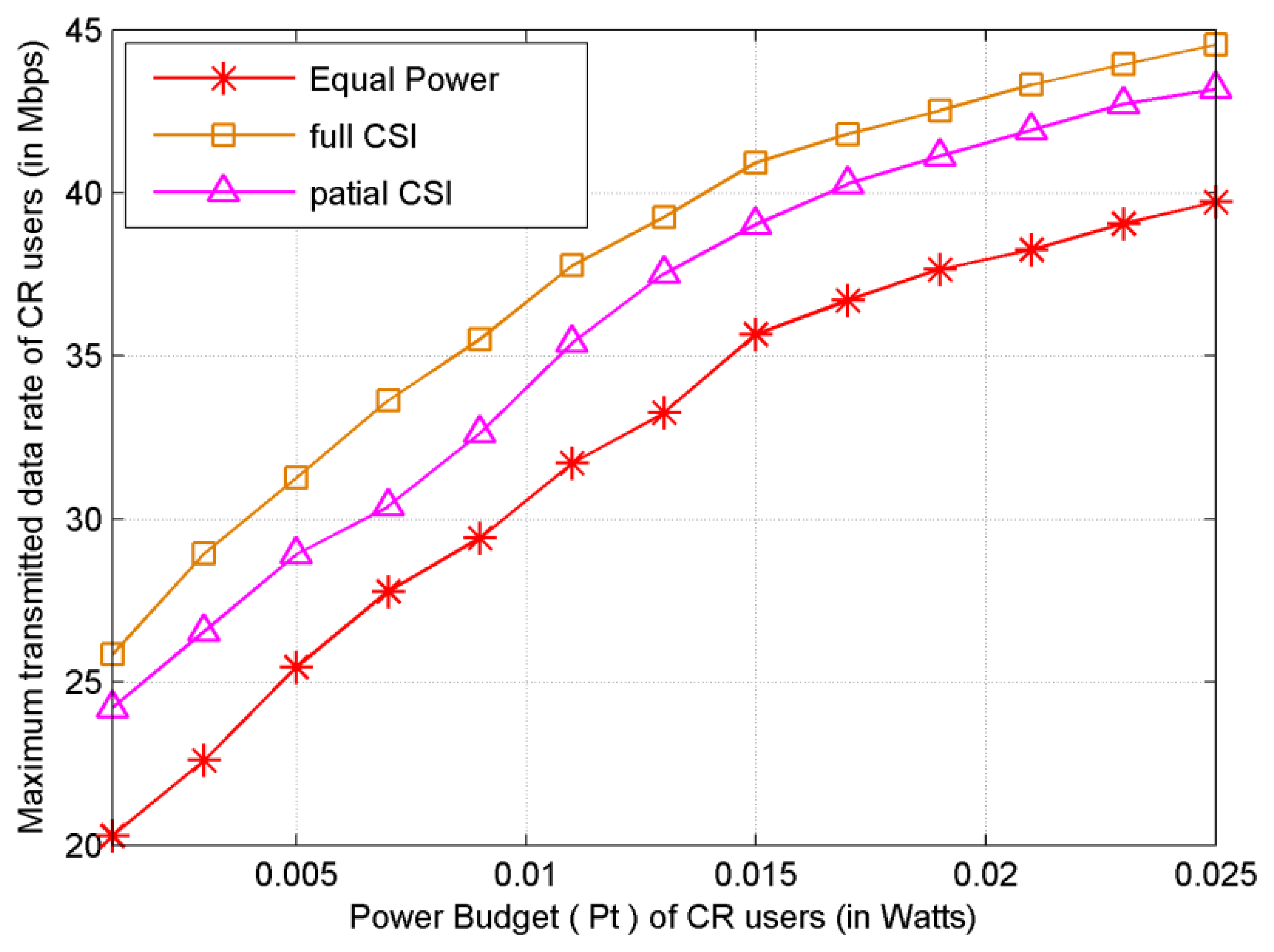
As shown in Figure 8, the performance of proposed subcarrier-pair based resource allocation algorithm is presented for the case that each SU has no CSI of non-adjacent link. It is shown that the system transmitted data rate decreases due to limited CSI compared to that of full CSI scenario. However, this scheme does not require the full CSI of non-adjacent link at each cooperative SU. Moreover, we show that the transmitted data rate of the proposed subcarrier-pair based resource allocation algorithm with partial CSI significantly outperforms that of EPA. The transmitted data rate is close to that of subcarrier-pair based resource allocation algorithm with full CSI.
4.5. The Transmitted Data Rate Obtained by SUs under Different Distance
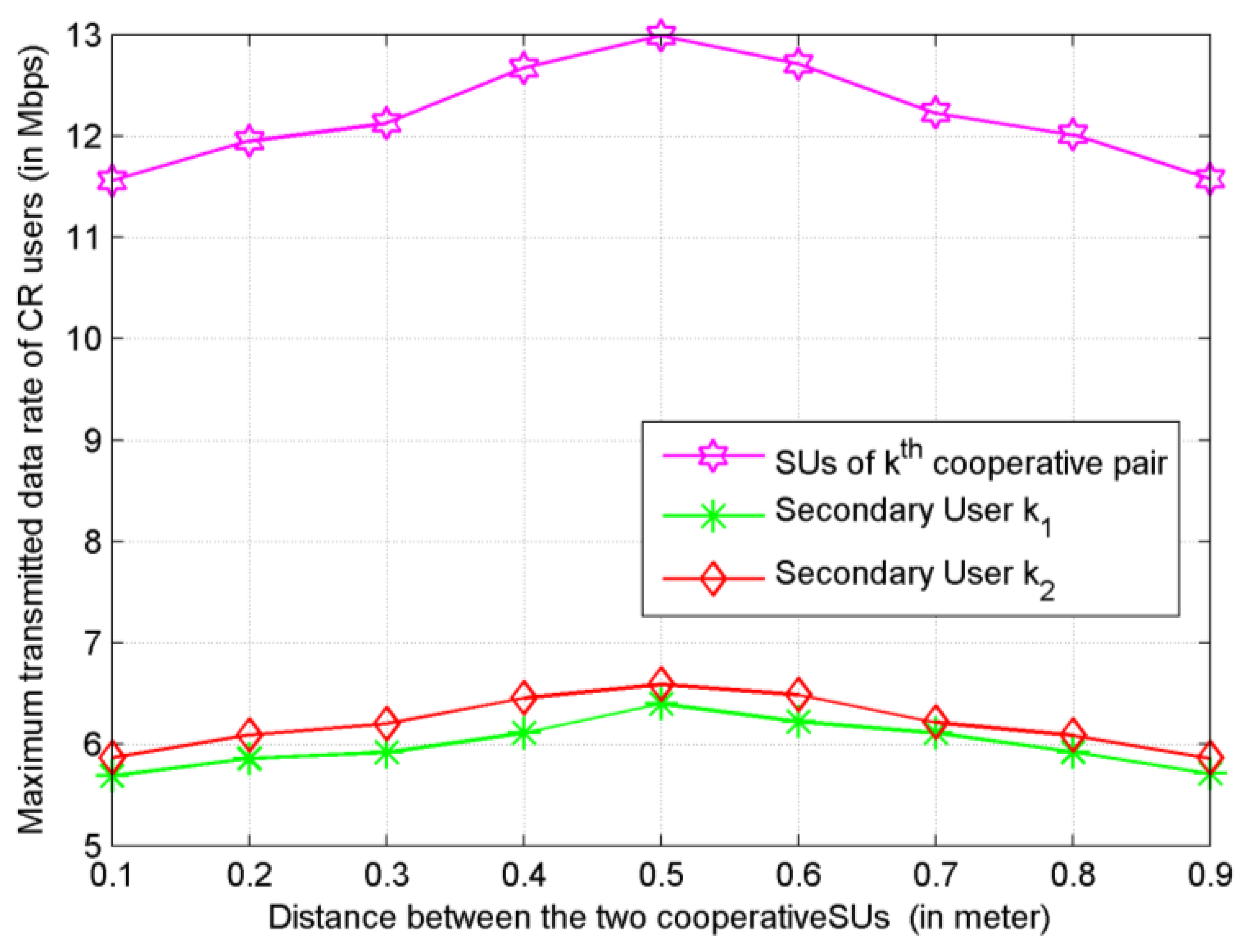
Last but not least, we have also studied how the distance between cooperative SUs impacts on the system performance. Under the proposed subcarrier-pair based resource allocation algorithm with proportional fairness, Figure 9 shows that the system has comparatively better performance when d ∈ [0.4, 0.6] This result provides a guideline for grouping and partner selection in user cooperative networks.
5. Conclusions
In this paper, we have developed a novel subcarrier-pair based resource allocation algorithm that maximizes the transmission data rate while the interference introduced to the PUs remains within a given limit. Using the proportional fairness as the optimized objective function, we can improve proportional fairness of resource allocation and achieve substantial transmitted data rate gains. The sum of power constraint for the source and relay nodes are considered. Moreover, we extended the analysis to the case that the CSI of nonadjacent link is not available at cooperative SUs, and found that even in this case the proposed schemes perform better than the classical schemes.
Compared to the existing resource allocation algorithms which are introduced in the paper, our algorithm considers that each secondary relay user has its own data to be transmitted. Simulation results have shown that, either in improving the system throughput or in improving fairness of resource allocation, the proposed subcarrier-pair based resource allocation algorithm offers the best performance conditions among several existing compared resource allocation algorithms under various power budgets, while keeping the interference introduced to PU bands below a specified threshold. Besides, the transmitted data rate of proposed subcarrier-pair based resource allocation algorithm obviously outperforms that of EPA scheme when only partial CSI can be obtained by SUs. The contribution by taking full advantage of the statistical non-adjacent links channel information is demonstrated clearly in the simulation results. In addition, we notice that the system efficiency loss of partial CSI scheme compared to that of full CSI scheme is acceptable.
Acknowledgments
This research was supported by the key project of Tianjin Key Technology R&D Program (09ZCKFGX29200) of China.
Conflict of Interest
The authors declare no conflict of interest.
References
- Simon, H. Cognitive radio brain-empowered wireless communications. IEEE J. Sel. Areas Commun. 2005, 23, 201–220. [Google Scholar]
- Liang, Y.C.; Chen, K.C.; Li, G.Y. Cognitive radio networking and communications: An overview. IEEE Trans. Veh. Technol. 2011, 60, 3386–3407. [Google Scholar]
- Laneman, J.N.; Tse, D.N.C.; Wornell, G.W. Cooperative diversity in wireless networks: Efficient protocols and outage behavior. IEEE Trans. Inf. Theory 2004, 50, 3062–3080. [Google Scholar]
- Choi, Y.J.; Pak, W.; Xin, Y.; Rangarajan, S. Throughput analysis of cooperative spectrum sensing in Rayleigh-faded cognitive radio systems. IET Commun. 2012, 6, 1104–1110. [Google Scholar]
- Kang, X.; Liang, Y-C.; Nallanathan, A. Optimal power allocation for fading channels in cognitive radio networks: Ergodic capacity and outage capacity. IEEE Trans. Wirel. Commun. 2009, 8, 940–950. [Google Scholar]
- Kang, X.; Zhang, R.; Liang, Y.-C. Optimal power allocation strategies for fading cognitive radio channels with primary users outage constraint. IEEE J. Sel. Areas Commun. 2011, 29, 374–383. [Google Scholar]
- Liu, J.; Shroff, N.B.; Sherali, H.D. Optimal power allocation in multi-relay MIMO cooperative networks: Theory and algorithms. IEEE J. Sel. Areas Commun. 2012, 30, 331–340. [Google Scholar]
- Kwangyul, K.; Yoan, S. An Improved Power Allocation Scheme Using Particle Swarm Optimization in Cooperative Wireless Communication Systems. Proceedings of the 17th Asia-Pacific Conference on Communications (APCC), Sabah, Malaysia, 2–5 October 2011; pp. 654–658.
- Oberoi, J.S.; Pareek, U.; Naeem, M. EDA-Based Joint Power, Subcarrier Allocation and Relay Assignment Scheme for Multiuser Relaying in OFDMA-Based Cognitive Radio Systems. Proceedings of the 2011 5th International Conference on Signal Processing and Communication Systems (ICSPCS), Honolulu, HI, USA, 12–14 December 2011; pp. 1–7.
- Ding, Z.G.; Chin, W.H.; Leung, K.K. Distributed beamforming and power allocation for cooperative networks. IEEE Trans. Wirel. Commun. 2008, 7, 1817–1822. [Google Scholar]
- Luo, J.; Blum, R.S.; Cimini, L.J. Decode-and-forward cooperative diversity with power allocation in wireless networks. IEEE Trans. Wirel. Commun. 2007, 6, 793–799. [Google Scholar]
- Pan, Y.W.; Nix, A.; Beach, M. Distributed resource allocation for OFDMA-based relay networks. IEEE Trans. Veh. Technol. 2011, 60, 919–931. [Google Scholar]
- Shen, Y.Y.; Feng, G.; Yang, B. Fair resource allocation and admission control in wireless multiuser amplify-and-forward relay networks. IEEE Trans. Veh. Technol. 2012, 61, 1383–1397. [Google Scholar]
- Salem, M.; Adinoyi, A.; Rahman, M.; Yanikomeroglu, H.; Falconer, D.; Kim, Y.D. Fairness-aware radio resource management in downlink OFDMA cellular relay networks. IEEE Trans. Wirel. Commun. 2010, 9, 1628–1639. [Google Scholar]
- Vu, H.N.; Kong, H.-Y. Joint subcarrier matching and power allocation in OFDM two-way relay systems. J. Commun. Netw. 2012, 14, 257–266. [Google Scholar]
- Boostanimehr, H.; Bhargava, V.K. Selective subcarrier pairing and power allocation for DF OFDM relay systems with perfect and partial CSI. IEEE Trans. Wirel. Commun. 2011, 10, 4057–4067. [Google Scholar]
- Dang, W.B.; Tao, M.X.; Mu, H. Subcarrier-pair based resource allocation for cooperative multi-relay OFDM systems. IEEE Trans. Wirel. Commun. 2010, 9, 1640–1649. [Google Scholar]
- Sendonaris, A.; Erkip, E.; Aazhang, B. User cooperation diversity part I: System description. IEEE Trans. Commun. 2003, 51, 1927–1938. [Google Scholar]
- Tourki, K.; Gesbert, D.; Deneire, L. Cooperative Diversity Using Per-User Power Control in the Multiuser MAC Channel. Proceedings of the 2007 IEEE International Symposium on Information Theory, Nice, France, 24–29 June 2007; pp. 1911–1915.
- Maciel, T.F.; Klein, A. On the performance, complexity, and fairness of suboptimal resource allocation for multiuser MIMO-OFDMA systems. IEEE Trans. Veh. Technol. 2010, 59, 406–419. [Google Scholar]
- Papoutsis, V.D.; Fraimis, I.G.; Kotsopoulos, S.A. User selection and resource allocation algorithm with fairness in MISO-OFDMA. IEEE Commun. Lett. 2010, 14, 411–413. [Google Scholar]
- Lu, W.S.; Ji, F.; Yu, H. A general resource allocation algorithm with fairness for SDMA/MISO/OFDMA systems. IEEE Commun. Lett. 2011, 15, 1072–1074. [Google Scholar]
- Wu, J.; Yang, L.X.; Liu, X. Subcarrier and Power allocation in OFDM Based Cognitive Radio Systems. Proceedings of the 2011 Fourth International Conference on Intelligent Computation Technology and Automation (ICICTA), Shenzhen, China, 28–29 March 2011; pp. 728–731.
- Mohanram, C.; Bhashyam, S. A sub-optimal joint subcarrier and power allocation algorithm for multiuser OFDM. IEEE Commun. Lett. 2005, 9, 685–687. [Google Scholar]
- Tan, C.K.; Chuah, T.C.; Tan, S.W. Fair subcarrier and power allocation for multiuser orthogonal frequency-division multiple access cognitive radio networks using a Colonel Blotto game. IET Commun. 2011, 5, 1607–1618. [Google Scholar]
- Mohamad, K.A.; Veluppillai, M.; Mehri, M. A dual-decomposition-based resource allocation for OFDMA networks with imperfect CSI. IEEE Trans. Veh. Technol. 2010, 59, 2394–2403. [Google Scholar]
- Chen, C.-H.; Wang, C.-L.; Chen, C.-T. A resource allocation scheme for cooperative multiuser OFDM-based cognitive radio systems. IEEE Trans. Commun. 2011, 59, 3204–3215. [Google Scholar]
- Yaacoub, E.; Dawy, Z. A survey on uplink resource allocation in OFDMA wireless networks. IEEE Commun. Surv. Tutor. 2012, 14, 322–337. [Google Scholar]
- Nader, M.; Keivan, N.; Mohammad, G.K. Downlink radio resource allocation in OFDMA spectrum sharing environment with partial channel state information. IEEE Trans. Wirel. Commun. 2011, 10, 3482–3495. [Google Scholar]
- Choi, K.W.; Hossain, E.; Kim, D.I. Downlink subchannel and power allocation in multi-cell OFDMA cognitive radio networks. IEEE Trans. Wirel. Commun. 2011, 10, 2259–2271. [Google Scholar]
- Tianxiang, L.; Feifei, G.; Xian-Da, Z. Joint resource scheduling for relay-assisted broadband cognitive radio networks. IEEE Trans. Wirel. Commun. 2012, 11, 3090–4000. [Google Scholar]
- Sabit, E.; Mohamed, M.A.; Khalid, A.Q. Random subcarrier allocation in OFDM-based cognitive radio networks. IEEE Trans. Signal Process. 2012, 60, 4758–4774. [Google Scholar]
- Xu, H.; Li, B.C. Resource allocation with flexible channel cooperation in cognitive radio networks. IEEE Trans. Mob. Comput. 2013, 12, 957–970. [Google Scholar]
- Bansal, G.; Hossain, M.D.J.; Bhargava, V.K. Subcarrier and power allocation for OFDMA-based cognitive radio systems with joint overlay and underlay spectrum access mechanism. IEEE Trans. Veh. Technol. 2013, 62, 1111–1122. [Google Scholar]
- Naeem, M.; Pareek, U.; Lee, D.C.; Anpalagan, A. Estimation of distribution algorithm for resource allocation in green cooperative cognitive radio sensor networks. Sensors 2013, 13, 4884–4905. [Google Scholar]
- Viswanath, P.; Tse, D.N.C.; Laroia, R. Opportunistic beamforming using dumb antennas. IEEE Trans. Inf. Theory. 2002, 48, 1277–1294. [Google Scholar]
- Bansal, G.; Hossain, M.D.J.; Bhargava, V.K. Optimal and suboptimal power allocation schemes for OFDM-based cognitive radio systems. IEEE Trans. Wirel. Commun. 2008, 7, 4710–4718. [Google Scholar]
- Sami, M.A.; Gordon, L.S. Interference-aware radio resource allocation in OFDMA-based cognitive radio networks. IEEE Trans. Veh. Technol. 2011, 60, 1699–1713. [Google Scholar]
- Kang, X.; Garg, H.K.; Liang, Y.-C. Optimal power allocation for OFDM-based cognitive radio with new primary transmission protection criteria. IEEE Trans. Wirel. Commun. 2010, 9, 2066–2075. [Google Scholar]
- Liu, Y.; Chen, W. Limited-feedback-based adaptive power allocation and subcarrier pairing for OFDM DF relay. IEEE Trans. Veh. Technol. 2012, 61, 2559–2571. [Google Scholar]
- Sharma, S.; Shi, Y.; Liu, J. Network coding in cooperative communications: Friend or foe? IEEE Trans. Mob. Comput. 2012, 11, 1073–1085. [Google Scholar]
- Zhang, Q.; Zhang, J.M.; Shao, C.J. Power Allocation for Regenerative Relay Channel with Rayleigh Fading. Proceedings of IEEE 59th Vehicular Technology Conference (VTC 2004), Milan, Italy, 17–19 May 2004; pp. 1167–1171.
- Le, L.B.; Hossain, E. Resource allocation for spectrum underlay in cognitive radio networks. IEEE Trans. Wirel. Commun. 2008, 7, 5306–5315. [Google Scholar]
- Kelly, F.P.; Maulloo, A.K.; Tan, D.K.H. Rate control in communication networks: Shadow prices, proportional fairness and stability. J. Oper. Res. Soc. 1998, 49, 237–252. [Google Scholar]
- Kim, H.; Keunyoung, K.; Youngnam, H. A Proportional Fair Scheduling for Multicarrier Transmission Systems. Proceedings of IEEE 60th Vehicular Technology Conference (VTC2004-Fall), Los Angeles, CA, USA, 26–29 September 2004; pp. 409–413.
- Shen, Z.; Andrews, J.G.; Evans, B.L. Adaptive resource allocation in multiuser OFDM systems with proportional rate constraints. IEEE Trans. Wirel. Commun. 2005, 4, 2726–2737. [Google Scholar]
- Ma, Y.-T.; Lin, X.Q. Power Allocation with Proportional Fairness in User Cooperation Networks. Proceedings of the 19th Annual Wireless and Optical Communications Conference (WOCC), Shanghai, China, 14–15 May 2010; pp. 1–5.
- Host-Madsen, A.; Zhang, J.S. Capacity bounds and power allocation for wireless relay channels. IEEE Trans. Inf. Theory. 2005, 51, 2020–2040. [Google Scholar]
- Gradshteyn, I.S.; Ryzhik, I.M. Table of Integrals, Series, and Products, 7th ed.; Academic Press: San Diego, CA, USA, 2007. [Google Scholar]


| Symbol | Definition |
|---|---|
| K | Number of cooperative partners in the CR network |
| N | Number of subcarriers |
| Δf | Bandwidth of a subcarrier |
| Ts | Length of a slot |
| Transmission power of k1th SU on subcarrier n in the first frame | |
| Transmission power of k1th SU on subcarrier n in the second frame | |
| Transmission power of k2th SU on subcarrier n in the first frame | |
| Transmission power of k2th SU on subcarrier n in the second frame | |
| the channel gain of the communication link from the kith SU to the kj th SU user on the nth subcarrier | |
| the channel gain of the communication link from the kith SU to AP on the nth subcarrier | |
| the channel gain of the interference link from lth PU to kith SU user receiver on the nth subcarrier | |
| the channel gain of the interference link from lth PU to kith SU user receiver on the nth subcarrier | |
| the channel gain of the interference link from lth PU to AP receiver on the nth subcarrier | |
| the additive noises at the corresponding node | |
| the interference introduced by the PUs into corresponding node |
| T1 in First Frame | T2 in First Frame | T1 in Second Frame | T2 in Second Frame | |
|---|---|---|---|---|
| SUk1 | 0 | 0 | ||
| SUk2 | 0 | 0 |
| Parameter | Value |
|---|---|
| Number of cooperative partners K | 4 |
| Number of PUs L | 2 |
| Number of subcarriers N | 20 |
| Length of a slot Ts | 4u s |
| value of amplitude PPU | 10 × 10−3 W |
| Ith(l) (l = 1,2) | 2.7 × 10⁻³ W |
| average channel power gain | 10 dB |
| △ f | 0.315 MHz |
| B2 | 1 MHz |
| B2 | 2 MHz |
© 2013 by the authors; licensee MDPI, Basel, Switzerland. This article is an open access article distributed under the terms and conditions of the Creative Commons Attribution license (http://creativecommons.org/licenses/by/3.0/).
Share and Cite
Ma, Y.; Zhou, L.; Liu, K. A Subcarrier-Pair Based Resource Allocation Scheme Using Proportional Fairness for Cooperative OFDM-Based Cognitive Radio Networks. Sensors 2013, 13, 10306-10332. https://doi.org/10.3390/s130810306
Ma Y, Zhou L, Liu K. A Subcarrier-Pair Based Resource Allocation Scheme Using Proportional Fairness for Cooperative OFDM-Based Cognitive Radio Networks. Sensors. 2013; 13(8):10306-10332. https://doi.org/10.3390/s130810306
Chicago/Turabian StyleMa, Yongtao, Liuji Zhou, and Kaihua Liu. 2013. "A Subcarrier-Pair Based Resource Allocation Scheme Using Proportional Fairness for Cooperative OFDM-Based Cognitive Radio Networks" Sensors 13, no. 8: 10306-10332. https://doi.org/10.3390/s130810306
APA StyleMa, Y., Zhou, L., & Liu, K. (2013). A Subcarrier-Pair Based Resource Allocation Scheme Using Proportional Fairness for Cooperative OFDM-Based Cognitive Radio Networks. Sensors, 13(8), 10306-10332. https://doi.org/10.3390/s130810306