Article

Synthesis of Densely Immobilized Gold-Assembled Silica Nanostructures

1
Department of Bioscience and Biotechnology, Konkuk University, Seoul 143-701, Korea
2
Department of Chemical and Biological Engineering, Hanbat National University, Daejeon 34158, Korea
*
Author to whom correspondence should be addressed.
Int. J. Mol. Sci. 2021, 22(5), 2543; https://doi.org/10.3390/ijms22052543
Submission received: 10 February 2021 / Revised: 25 February 2021 / Accepted: 26 February 2021 / Published: 3 March 2021
(This article belongs to the Special Issue Metal Nano/Microparticles for Bioapplications)

Abstract

:
In this study, dense gold-assembled SiO2 nanostructure (SiO2@Au) was successfully developed using the Au seed-mediated growth. First, SiO2 (150 nm) was prepared, modified by amino groups, and incubated by gold nanoparticles (ca. 3 nm Au metal nanoparticles (NPs)) to immobilize Au NPs to SiO2 surface. Then, Au NPs were grown on the prepared SiO2@Au seed by reducing chloroauric acid (HAuCl4) by ascorbic acid (AA) in the presence of polyvinylpyrrolidone (PVP). The presence of bigger (ca. 20 nm) Au NPs on the SiO2 surface was confirmed by transmittance electronic microscopy (TEM) images, color changes to dark blue, and UV-vis spectra broadening in the range of 450 to 750 nm. The SiO2@Au nanostructure showed several advantages compared to the hydrofluoric acid (HF)-treated SiO2@Au, such as easy separation, surface modification stability by 11-mercaptopundecanoic acid (R-COOH), 11-mercapto-1-undecanol (R-OH), and 1-undecanethiol (R-CH3), and a better peroxidase-like catalysis activity for 5,5′-Tetramethylbenzidine (TMB) and hydrogen peroxide (H2O2) reaction. The catalytic activity of SiO2@Au was two times better than that of HF-treated SiO2@Au. When SiO2@Au nanostructure was used as a surface enhanced Raman scattering (SERS) substrate, the signal of 4-aminophenol (4-ATP) on the surface of SiO2@Au was also stronger than that of HF-treated SiO2@Au. This study provides a potential method for nanoparticle preparation which can be replaced for Au NPs in further research and development.

1. Introduction

Metal nanoparticles (NPs) have attracted much attention due to their quantum size effect resulting in unique physical and chemical properties [1]. Among metal nanostructures, gold (Au) nanostructures are probably the most remarkable metal materials due to their particular features: ease of synthesis manipulation; large surface-to-volume ratio, enabling precise control over the particle’s physicochemical properties [2]; strong binding affinity to thiols, disulfides, and amines [3]; unique tunable optical properties due to their size- and shape-dependent biophysical and distinct optoelectronic properties [4,5,6,7]; excellent biocompatibility, chemical inertness, and low toxicity [8,9]. As a result, Au nanostructures have been outstanding tools for a variety of potential applications in catalysis [10,11,12,13,14,15] and biosensing [16,17,18,19,20,21,22].
Based on their dimensions, Au nanostructures are classified as one-dimensional (1D) nanostructures (nanorods, nanowires, nanotubes, nanobelts); two-dimensional (2D) nanostructures (nanoplates such as nanoparticles, stars, pentagons, squares/rectangles, dimpled nanoplates, hexagons, truncated triangles); and three-dimensional (3D) nanostructures (nanotadpoles, nanodumbbells, nanopods, nanostars, and nanodendrites) [23]. Even though spherical or quasi-spherical Au NPs have received the most attention because of the ease of synthesis manipulation, anisotropically Au nanostructures exhibit unique physical and optical properties, such as low percolation threshold and surface plasmon resonance (SPR) [24]. In addition, the optical properties of anisotropic Au nanostructure such as the hollow nanoshell, and nanorods can be tunable with their shape in the visible region and in the near infrared (NIR) region. This property has given rise to the opportunity for using anisotropic Au nanostructures as composite therapeutic agents in clinical medical applications such as diagnostics and therapy [25]. However, the synthesis of higher-dimensional Au nanostructures usually requires specific templates for guiding anisotropic growth [26]. Many templates have been utilized, including biomolecules (DNA), polymers, surfactants, inorganic nanowires, and lithographical patterns [27,28,29,30,31]. However, the synthesis of anisotropic Au nanostructures with precise control of morphology remains a great challenge.
Recently, our group reported Au–Ag alloys assembled SiO2 (SiO2@Au–Ag) nanostructure as a strong and reliable surface enhanced Raman scattering (SERS) probe using SiO2 as a template [32,33,34,35]. SiO2 NPs are inert and their sizes are easily controllable [32]. Furthermore, the density of Au NPs, nanogaps, size and shape of nanostructure can be controlled by SiO2 template, generating a homogenous SERS substrate [36]. The density of the Au NPs and the gaps between two Au NPs on the surface of SiO2 can be tunable and provide a stronger localized surface plasmon resonance (LSPR) property. As a result, SiO2@Au–Ag can be developed as high-strength and reliable SERS substrates for the enzyme-linked immunosorbent assay (ELISA) [37,38], which is an internal SERS [34,35], pesticide detection standard [39], and provides detection of toxic chemical compound in pharmaceutics [40]. However, the cellular toxicity and easy oxidation of intrinsic Ag of our nanostructure limits their application in vivo [41,42]. Even though some research groups have investigated the attachment of Au NP on the surface of SiO2, the particle density on the SiO2 surface was nearly low or non-uniform [43,44,45,46,47,48]. Therefore, we used the combination of SiO2 core template and seed-growth methods in this study to develop a new Au-based SiO2 nanostructure with dense Au density on the surface of SiO2. This study provides a potential method for preparation of nanoparticles including noble metal that can be replaced for spherical Au NPs, which supports further research and development.

2. Results and Discussion

To prepare SiO2 nanostructure (SiO2@Au), silica NPs (~150 nm) were first functionalized by 3-aminopropyltriethoxysilane (APTS) to prepare aminated silica NPs, as shown in Figure 1a. Simultaneously, colloidal Au NPs (3 nm) were synthesized by tetrakis(hydroxymethyl)phosphonium chloride (THPC) and incubated with the aminated silica NPs to prepare Au NPs seed embedded with SiO2 (SiO2@Au seed NPs), according to the method reported by Pham et al. [32,33,34,35,39]. Subsequently, the Au NPs on the surface of SiO2@Au seed were grown by reducing a gold precursor (HAuCl4) in the presence of ascorbic acid (AA) and polyvinylpyrrolidone (PVP) as a stabilizer and structure-directing agent under mild reducing conditions [32]. The gold ions reduced by AA were selectively grown onto SiO2@Au seed to increase the size of Au on the surface of SiO2 NPs to generate SiO2@Au.

2.1. Synthesis of SiO2@Au Nanostructure

We investigated the characteristics of SiO2@Au synthesized by reduction of HAuCl4 and AA in the presence of PVP. Figure 1b shows the optical images of nanostructures in our research. SiO2 NPs with ca. 150 nm in diameter are shown in a transparent solution in Figure 1b(i). When Au NPs were coated and grown on the surface of aminated SiO2, the color of the solution changed to light brown, as shown in Figure 1b(ii). Then, 2, 5, and 10 mg of SiO2@NH2 were incubated in 10 mL Au NPs suspension overnight (Figure S1a). The surface of SiO2 NPs was decorated with many small Au NPs to generate the SiO2@Au seed (Figure 1b(ii) and Figure S1a). The Au NPs density on the SiO2 surface became inversed with the amount of SiO2 used. Then, 1 mg of SiO2@Au seed was used for a growth of Au NPs on the SiO2 in Figure S1b–d. The sizes of Au NPs seed on the SiO2@Au surface increased with the Au3+ concentration in the range of 100 to 300 µM at all 2, 5, and 10 mg SiO2@NH2 (Figure S1b–d). The ultraviolet-visible (UV-Vis) spectra of obtained SiO2@Au nanostructures synthesized at different concentrations of Au3+ were investigated in Figure S1e. The optical property of SiO2@Au was slightly tunable by adjusting the Au3+ concentration in the range of 100 to 300 µM. At 100 µM Au3+, the maximum absorbance peaks of obtained SiO2@Au synthesized by 2, 5, and 10 mg SiO2@NH2 were observed at 523, 522, and 521 nm, respectively. Whereas these peaks were red-shifted to 547, 543, and 541 nm at 200 µM Au3+ and 571, 561, and 572 nm at 300 µM Au3+, respectively. These results were consistent with the Mie’s theory which states that an increase of particle size leads the electric surface charge density and shifts the plasmon absorption band to longer wavelengths [23]. However, it is difficult to obtain the different desired SiO2@Au nanostructures as expected when using 1 mg SiO2@Au seed. The final size of Au NPs is dependent on the number of seeds and total concentration of Au3+ in the growth solution [49]. In our study, the Au3+ concentration in the growth solution was fixed at 100, 200, and 300 µM. Therefore, the final size of Au NPs on the surface of SiO2 depended on the number of SiO2@Au seeds (or SiO2@Au seed amount). Indeed, 1 mg of SiO2@Au seed was used for Au NPs growth process in our study, which resulted in Au NPs on the SiO2 surface not being able to grow larger as seen in the TEM images and UV-Vis spectra (Figure S1). To obtain a monodisperse SiO2@Au nanostructure, the SiO2@Au seed was therefore decreased to 0.2 mg for the growth of Au NPs on the SiO2 NPs in the next study. When 0.2 mg SiO2@Au seed was used as seed, the color of the obtained SiO2@Au suspension obviously changed from light brown to dark blue when the Au3+ concentration increased to 150 µM, as shown in Figure 1b(iii). According to the literature, Au NPs exhibit color and LSPR bands in the visible light that are dependent on size and shape [49,50,51,52]. Any changes in the absorbance or wavelength of the LSPR band provide a difference in size, shape, and aggregation state. This result indicated that the growth of Au NPs on the SiO2 surface was well performed and the absorbance, transmission, and reflection of light passed through the SiO2@Au suspension were also different at various synthesis conditions of SiO2@Au nanostructures. The UV-Vis spectra of the SiO2@Au nanostructures synthesized at 150 µM Au3+ were investigated in Figure 1c to show additional characteristics of SiO2@Au nanostructures. The suspension of SiO2 and SiO2@Au seed did not show any absorbance in the range of 300–1000 nm because of its small Au NPs on the SiO2 surface [37,53]. Whereas the suspension of SiO2@Au synthesized at 150 µM Au3+ showed a broadband in the range of 450 to 750 nm with the maximum peak at 615 nm. Furthermore, the absorbance intensity of SiO2@Au nanostructure solution was sharply increased. Consistent with the UV-Vis spectra, the transmittance electronic microscopy (TEM) images of SiO2@Au nanostructures also showed that the size of Au NPs on the surface of SiO2@Au increased dramatically comparing to the SiO2@Au seed at 150 µM Au3+ (Figure 1d), which led to the sharp broadening of LSPR bands of UV-Vis spectrum. While the average size of SiO2@Au seed was 200 ± 9 nm (n = 170, Figure S2a), the average size of SiO2@Au was 211 ± 7 nm (n = 172, Figure S2b). Consequently, the red-shifted and broadened absorbance properties of SiO2@Au nanostructures indicated the growth of Au NPs to bigger size on the SiO2 surface [23,49]. Therefore, the SiO2@Au nanostructure synthesized at 150 µM Au3+ was used for further study.

2.2. Characteristics of SiO2@Au Nanostructure

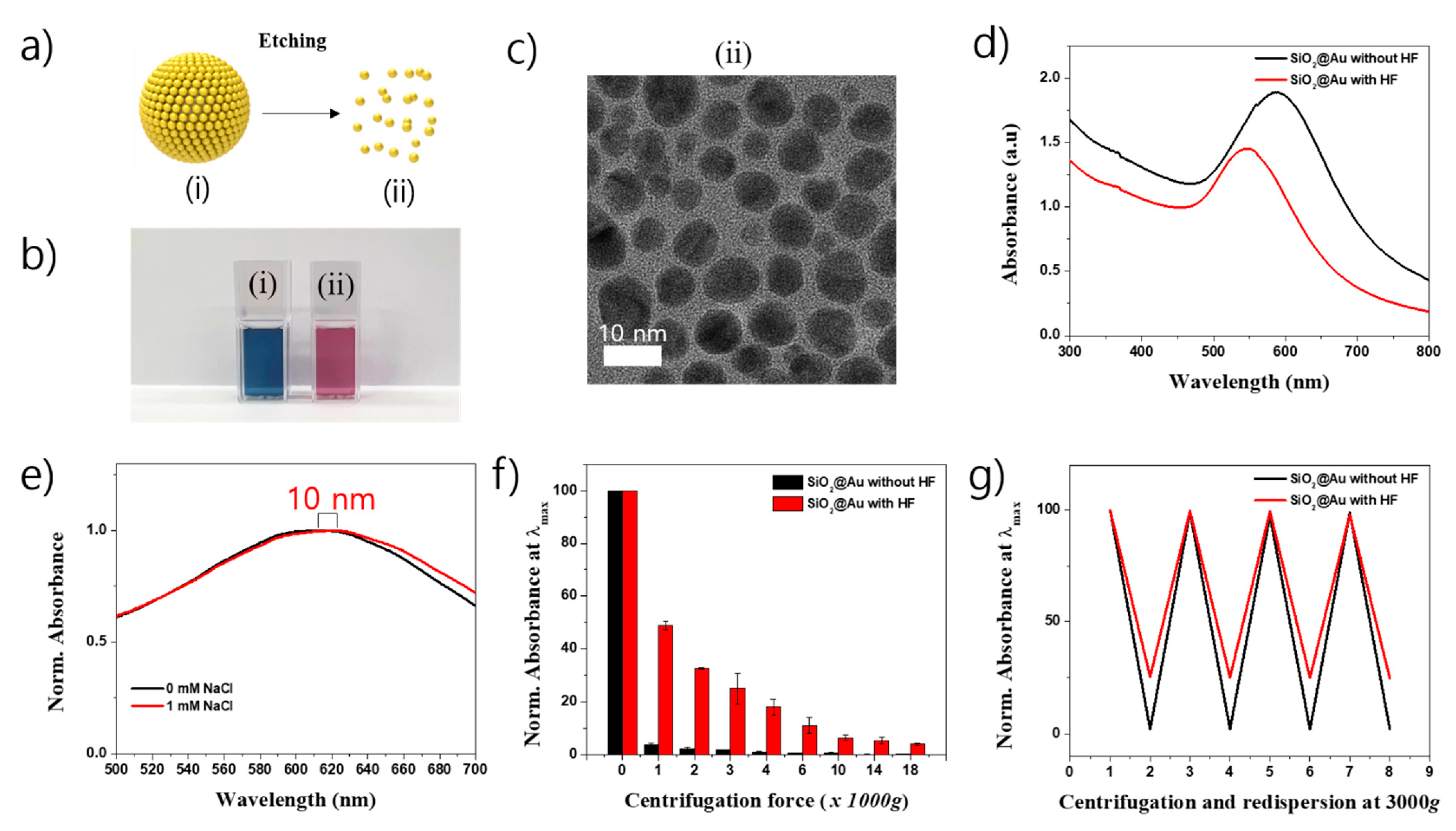
As shown in the previous study, the presence of SiO2 template in SiO2-based nanostructure facilitates the control of density, size, shape, and nanogap of metal NPs on the SiO2 surface [36]. It is believed that SiO2 template also facilitates the separation of SiO2-based nanostructures in reaction compared to those without SiO2 template. In our study, SiO2@Au nanostructure was first obtained from the growth reaction at 150 µM Au3+, then was incubated in 24% hydrofluoric acid (HF) to etch the SiO2 core template as seen in Figure 2a. Figure 2b shows an obvious color change from blue to pink when the SiO2 template was etched by HF. The TEM images of SiO2@Au nanostructure with HF treatment were collected. Figure 1d(iii) shows the morphology of SiO2@Au without HF treatment with the average size of 211 ± 7 nm (Figure S2b). Many Au NPs presented on the surface of SiO2 template. However, the nanostructure with HF treatment showed many small Au NPs with different shape (Figure 2c(ii)). The average size of Au NPs was 7.7 ± 1.5 nm (n = 172, Figure S2c). This meant that SiO2 core was completely etched and disappeared in SiO2@Au nanostructure and remained as small Au NPs. The optical properties of SiO2@Au with and without HF treatment (Au) were significantly different, as shown in Figure 2d. Both the maximum peak position and absorbance intensity of SiO2@Au with HF treatment (Au) decreased dramatically. The maximum peak position of SiO2@Au at 615 nm was blue-shifted to 546 nm when SiO2 core was etched. The difference in the LSPR wavelength and absorbance intensity of Au (SiO2@Au with HF treatment) was due to the difference in aggregation state of nanostructure that was caused by the disappearance of SiO2 core template [49]. To confirm the aggregation state of SiO2@Au with and without SiO2 core, the nanostructures were redispersed in 1 M NaCl. The maximum LSPR peak of SiO2@Au in NaCl showed a 10 nm red-shift compared to it in distilled water. Whereas SiO2@Au treated with HF was 22 nm red-shifted in 1 M NaCl (Figure S3). This indicates that SiO2@Au treated with HF was more easily aggregated than SiO2@Au without HF treatment.
The separation and redispersion of SiO2@Au nanostructures was also observed in Figure 2f,g and Figure S3b–d. The SiO2@Au with and without HF treatment were centrifuged at various centrifugation speeds in the range of 1000 to 18,000× g. The SiO2@Au was almost settled down to a bottle of microtube at a centrifugal speed of 3000× g and left a supernatant which showed a low absorbance. Meanwhile, the absorbance intensity of the supernatant of SiO2@Au treated with HF decreased gradually to 50% at 1000× g, 25% at 3000× g and 6.3% at 10,000× g. From these results, we concluded that SiO2@Au was easily centrifuged and separated from the reaction solution. In the next experiment, we carried out centrifuge and successively redispersed the SiO2@Au at the centrifugation speed of 3000× g. As seen in Figure 2g and Figure S3c, both SiO2@Au with and without HF treatment was easily redispersed in phosphate buffer saline containing 0.1% Tween 20 (PBST). Therefore, we concluded that the SiO2@Au nanostructures were easily separated and redispersed in PBST at mild conditions. The use of SiO2 as the core template opens up a new opportunity for easy preparation and separation of the nanostructure.

2.3. Surface Modification of SiO2@Au Nanostructure

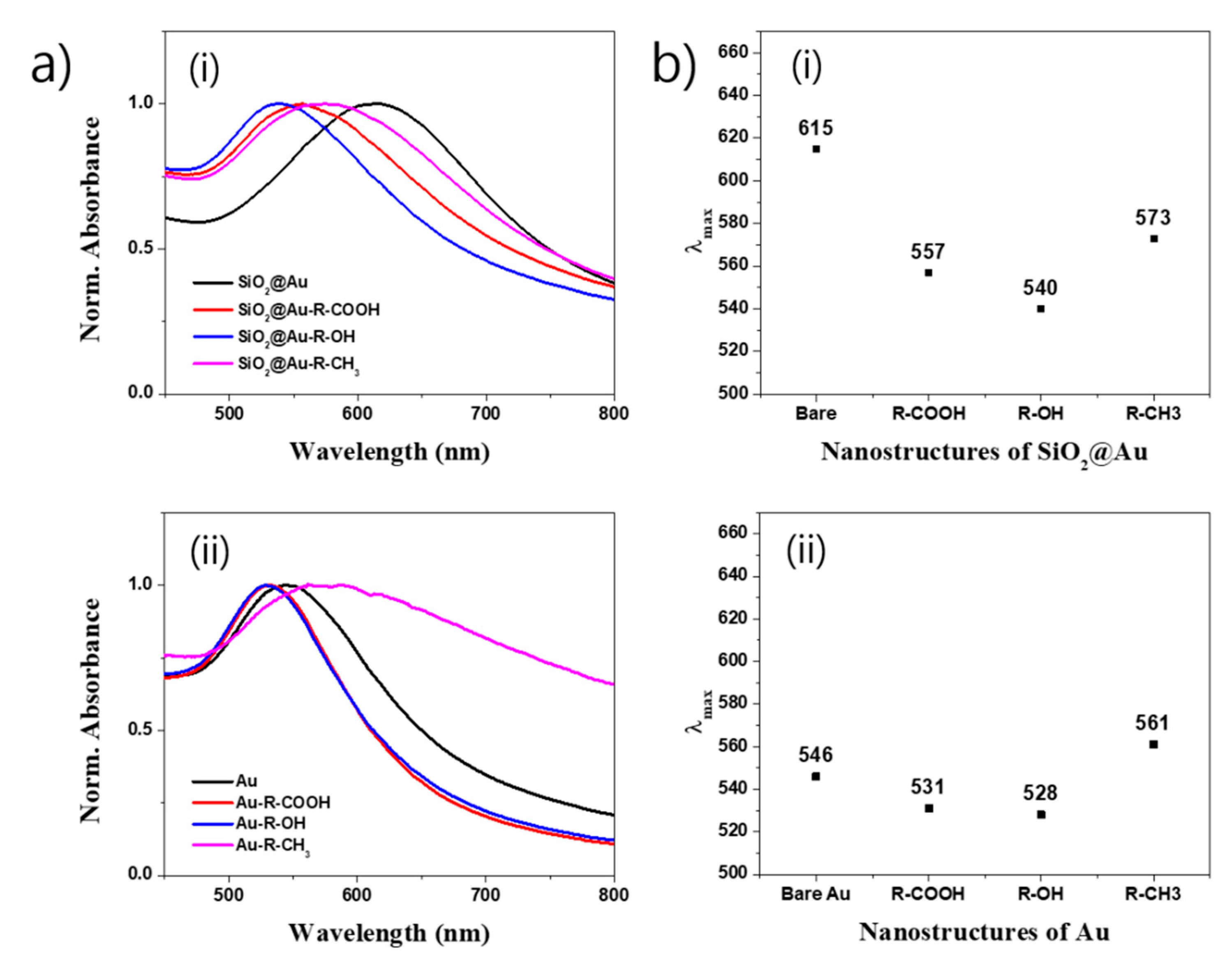
According to the literature, the electric field of the incident light induces polarization and excites the free conduction electron on the surface of the nanostructure to generate the LSPR spectrum. Therefore, any variation in the LSPR absorbance intensity or wavelength represents the difference in particle size, shape, aggregation state, as well as free electron cloud on the surface of the nanostructure [49,52]. We used the UV-Vis spectrum to observe the optical properties of the SiO2@Au nanostructures modified by three kinds of ligand (11-mercaptopundecanoic acid (R-COOH), 11-mercapto-1-undecanol (R-OH), and 1-undecanethiol (R-CH3)). Similarly, SiO2@Au which removed the SiO2 core by HF treatment was also used as a control sample to compare its optical properties to SiO2@Au nanostructures. The results are shown in Figure S4 and Figure 3. When R-COOH, R-CH3 and R-OH ligands were modified on the SiO2@Au surface, the absorbance intensities of all prepared SiO2@Au nanostructures obviously decreased (Figure S4). In addition, the extinction peak positions of SiO2@Au nanostructures modified by ligands were all blue-shifts (Figure 3a(i)). Maximum peak of SiO2@Au nanostructures modified by R-COOH ligand dramatically decreased 50 nm from 615 nm to 557 nm. Similarly, the SiO2@Au nanostructures modified by R-OH ligand also showed a 75 nm blue-shift to 540 nm and those modified by R-CH3 showed a 42 nm blue-shift to 573 nm, respectively (Figure 3b(i)). Meanwhile, the HF-treated SiO2@Au modified by R-COOH, R-OH, and R-CH3 ligands exhibited different behaviors (Figure 3a(ii)). Even though the extinction peak positions of the HF-treated SiO2@Au modified by R-COOH and R-OH also showed decreases in LSPR wavelength like those of SiO2@Au, the blue-shift differences in wavelength were small, just 15 and 18 nm for R-COOH and R-OH ligands, respectively (Figure 3b(ii)). Blue-shift decreases in wavelength of SiO2@Au nanostructures modified by R-COOH and R-OH are due to hydrophilic properties of OH and COOH groups of the modified nanostructure regardless of HF treatment. Interestingly, the HF-treated SiO2@Au modified by R-CH3 showed an opposite behavior compared to that of SiO2@Au nanostructure. While the SiO2@Au nanostructure modified by R-CH3 showed a blue-shift from 615 nm to 573 nm, the HF-treated SiO2@Au nanostructure modified by R-CH3 showed a red-shift from 546 to 561 nm. This indicates the presence of aggregation of the HF-treated SiO2@Au nanostructure modified by R-CH3. In contrast, presence of R-CH3 groups on the surface of SiO2@Au nanostructures showed little effect on the optical property of SiO2@Au nanostructure because of the big size of SiO2@Au (~211 nm) compared to HF-treated SiO2@Au (~8 nm). This is because of the intrinsic hydrophobic property of CH3 group strongly present on the surface of small Au, as shown in Figure 2c (~8 nm). The result was confirmed by replacing R-CH3 group by 4-aminophenol (4-ATP) with a benzene ring. Figure S5a,b show that the extinction bands of both SiO2@Au with and without HF treatment were red-shifted because of the intrinsic hydrophobic aromatic ring of 4-ATP. From these results, we once again concluded that the SiO2@Au nanostructure possessed a stable surface for ligand modification compared to that of Au NPs without the SiO2 core.

2.4. SERS and Peroxidase-Like Activity of SiO2@Au Nanostructure

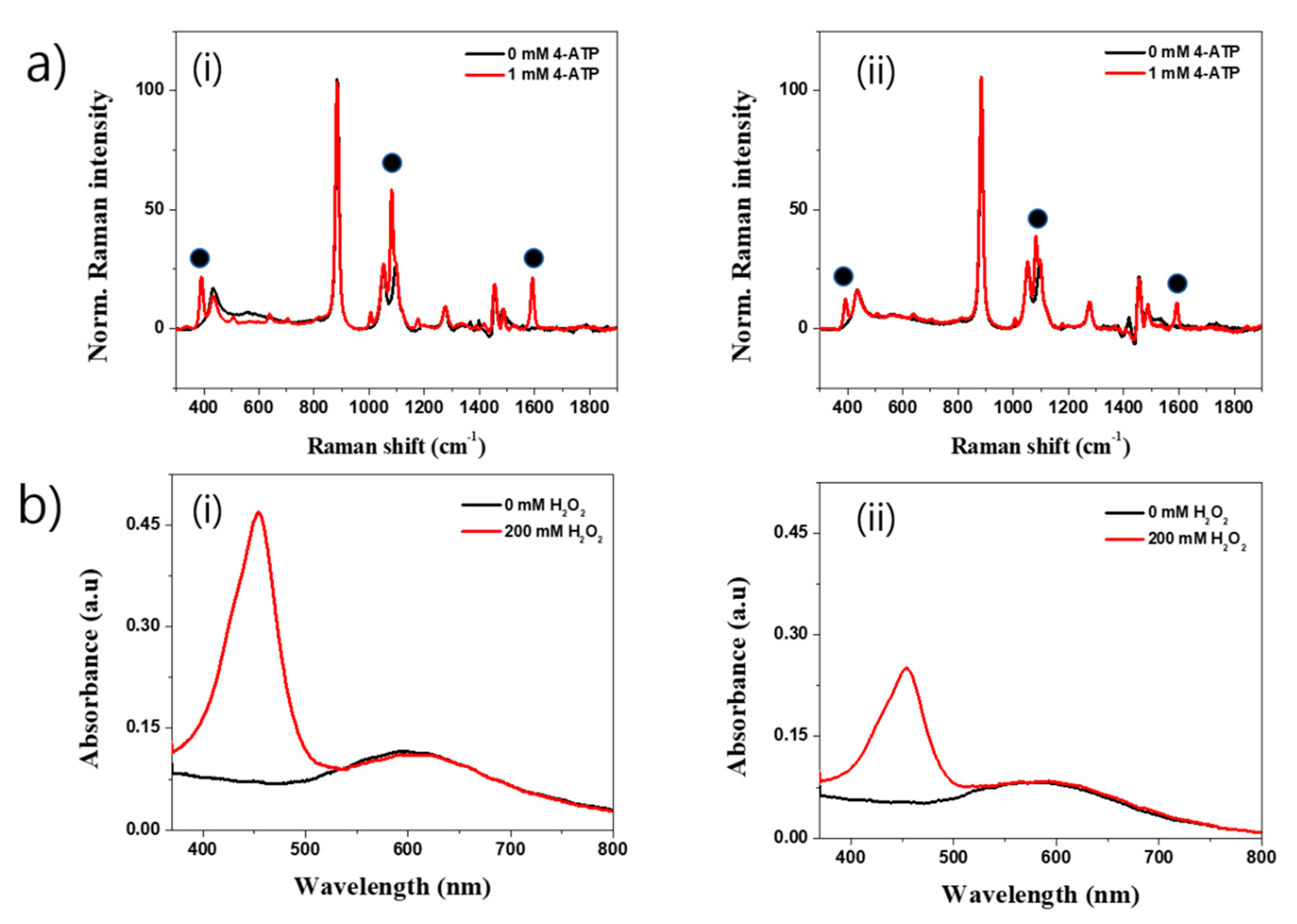
The application of the SiO2@Au nanostructure was briefly performed in our study. In SERS measurement, we used 4-ATP as a Raman reporter to observe the SERS properties of SiO2@Au with and without HF treatment using a 780 nm diode pump solid-state laser. Figure 4a shows the SERS spectra of SiO2@Au and HF-treated SiO2@Au before and after incubating in 1 mM 4-ATP solution. Although several Raman signals were shown in 4-ATP untreated condition, after incubating in 1 mM 4-ATP solution, typical bands of 4-ATP were clearly obtained for both SiO2@Au and HF-treated SiO2@Au due to the electromagnetic enhancement of the decorated Au NPs. Dominant and distinct bands were seen at 1081 cm−1 which were assigned to C-H in-plane bending vibration. The band at 1592 cm−1 and 391 cm−1 were attributed to C-C ring and C-S stretching, respectively [32]. Interestingly, the SERS bands at 391, 1081, and 1592 cm−1 of SiO2@Au were stronger than those of HF-treated SiO2@Au due to the hot spot generated by Au NPs on the surface of SiO2@Au. These results demonstrate the importance of pre-seeding Au NPs to ensure the growth of Au NPs onto the SiO2 surface to generate various hot spots, enhance the electromagnetic field on or near the surface of SiO2@Au, and amplify the SERS signal of SiO2@Au compared to HF-treated SiO2@Au without the SiO2 core template.
In addition, Au NPs-based nanostructures showed peroxidase-like catalytic activities in previous reports [54,55,56]. In this study, we used the SiO2@Au nanostructure to catalyze for 5,5′-Tetramethylbenzidine (TMB) and hydrogen peroxide (H2O2) reaction. Figure 4b shows the UV-Vis spectra of the SiO2@Au with and without HF treatment. In the presence of H2O2 and under the catalysis of nanostructures, TMB was oxidized to TMB+, followed by conversion to TMB2+ in sulfuric acid (H2SO4) condition as mentioned in Figure S4c. The presence of TMB2+ in reaction will show a clear absorbance peak at ~450 nm. Indeed, TMB was successfully converted to TMB2+ under the catalysis of the SiO2@Au by the presence of a clear and strong absorbance band at 453 nm (Figure 4b(i)). Similarly, the HF-treated SiO2@Au nanostructures could also convert TMB to TMB2+, as shown in in Figure 4b(ii). However, the absorbance intensity at 453 nm of the SiO2@Au was two times higher than that of the SiO2@Au with HF treatment. This is perhaps because of the easy aggregation of the HF-treated SiO2@Au nanostructure or because the surface of Au NPs was varied in the HF treatment as mentioned in a previous report [54].

3. Materials and Methods

3.1. Chemicals and Reagents

Tetraethylorthosilicate (TEOS), 3-aminopropyltriethoxysilane (APTS), tetrakis(hydroxymethyl)phosphonium chloride (THPC), polyvinylpyrrolidone (PVP), phosphate buffer saline (PBS), phosphate buffer saline containing 0.1% Tween 20 (PBST), ascorbic acid (AA), chloroauric acid (HAuCl4), hydrofluoric acid (HF), 4-aminothiophenol (4-ATP), 4-mercaptobenzoic acid (4-MBA), 1-undecanethiol (R-CH3), 11-mercaptopundecanoic acid (R-COOH), 11-mercapto-1-undecanol (R-OH), hydrogen peroxide (H2O2), and 5,5′-Tetramethylbenzidine (TMB) were purchased from Sigma-Aldrich (St. Louis, MO, USA). Ethanol (EtOH), sulfuric acid (H2SO4), buffer pH 4.0, and aqueous ammonium hydroxide (NH4OH, 27%) were purchased from Daejung (Sihung, Gyeonggi-do, South Korea); and ultrapure water (18.2 MΩ cm) was produced by a Millipore water purification system (EXL water purification; Vivagen Co., Seongnam, Gyeonggi-do, Korea).

3.2. Preparation of SiO2@Au NPs

The SiO2@Au seed was prepared as in the previous report [32,33]. The SiO2@Au NPs were prepared by incubating Au NPs suspension (10 mL) with aminated silica NPs (2 mg) overnight. The colloids were carefully centrifuged and washed thoroughly using EtOH. The NPs were then redispersed in 2.0 mL of 1 mg/mL PVP of obtained 1 mg/mL SiO2@Au seed.
The SiO2@Au NPs were carefully prepared via the reduction and deposition of Au using AA onto SiO2@Au seed in PVP. Moreover, 200 µL of SiO2@Au (1.0 mg/mL) was briefly dispersed in 9.8 mL of water that contained 10 mg of PVP under stirring. Thereafter, 20 µL of HAuCl4 (10 mM) was added to the suspension, followed by the addition of 40 µL of AA (10 mM). The suspension was incubated for 15 min to completely reduce the Au3+ ions to Au0. By repeating the reduction steps, the final Au3+ concentration was controlled to be 150 µM. The SiO2@Au NPs were obtained by the centrifugation of the suspension at 8500 rpm for 15 min, then the NPs were washed thoroughly using EtOH to remove any excess reagent. The SiO2@Au NPs were then redispersed in 1 mL of absolute EtOH to obtain a 200 µg/mL SiO2@Au NP suspension.

3.3. Etching of Silica Core of SiO2@Au NPs

In order to etch the silica core of SiO2@Au, 500 µL of SiO2@Au (100 µg/mL) in PBS solution which contained 0.1% Tween 20 (PBST), was added in 500 µL of 48% HF, followed by incubation for 24 h and centrifugation for 15 min at 17,000 rpm to obtain the Au NPs suspension. The prepared Au NPs were washed thoroughly using PBST to remove any excess reagent. The Au NPs were then redispersed in 1 mL of PBST, to obtain a 50 µg/mL Au NPs suspension.

3.4. Separation and Dispersion of SiO2@Au

First, 50 µg/mL SiO2@Au suspension was prepared in PBST and centrifuged for 10 min at various centrifugation speeds in the range of 1000 to 18,000× g. The supernatant was collected and the UV-Vis spectroscopy measured in the range of 300–800 nm. The pellet was redispersed by sonication. The centrifugation and redispersion were repeated until finishing. Similarly, the separation and redispersion of 50 µg/mL Au suspension was carried out as SiO2@Au suspension.

3.5. Surface Modification of SiO2@Au

SiO2@Au was incubated with 1 mM ligands, such as 1-undecanethiol (R-CH3), 11-mercaptopundecanoic acid (R-COOH), and 11-mercapto-1-undecanol (R-OH) for 6 h at room temperature to modify the surface of Au NPs by CH3, COOH, and OH groups, respectively. Briefly, 50 µg SiO2@Au suspension was prepared in 500 µL EtOH. Then, 2 mM ligand solutions (500 µL) were added into SiO2@Au suspension and incubated for 6 h under stirring. The nanostructure was collected at 17,000 rpm for 15 min and the obtained pellet was redispersed in 1000 µL PBST to obtain an SiO2@Au-ligand suspension. Similarly, the surface modification of Au NPs was carried out as SiO2@Au NPs.

3.6. Peroxidase-like Catalytic Activity of SiO2@Au

In order to obtain the peroxidase-like catalysis of nanostructures, TMB was dissolved in EtOH to obtain a stock solution of 10 mM TMB. Similarly, a stock solution of 2 M H2O2 was freshly prepared. Thereafter, 100 µL of 10 mM TMB, 700 µL of buffer pH 4.0, 100 µL of 2 M H2O2, and 100 µL of nanostructure (200 µg/mL) were incubated for 30 min at 25 °C in vortex mixer. The mixture was added to 500 µL of 1 M H2SO4 to stop the reaction and incubated for 10 min for color development. The suspension was measured by UV-Vis spectroscopy at 453 nm.

3.7. Instrument

Tranmission electron microscope images of the sample were captured by using Libra 120 field-emission transmission electron microscope (Carl Zeiss, Oberkochen, Baden-Württemberg, Germany) with a maximum accelerated voltage of 120 kV and JEM-F200 multi-purpose electron microscope (JEOL, Akishima, Tokyo, Japan) with a maximum accelerated voltage of 200 kV. Optical properties of the sample were observed by an Optizen POP UV/Vis spectrometer (Mecasys, Seoul, Korea). Centrifugation of the sample was performed by using a Microcentrifuge 1730R (LaboGene, Lyngen, Denmark). The Raman signal of nanostructure suspension in the capillary tube was recorded by a micro-Raman system (LabRam 300, JY-Horiba, Tokyo, Japan) equipped with an optical microscope (BX41, Olympus, Tokyo, Japan). The SERS signals were collected with a back-scattering geometry using a ×10 objective lens (0.90 NA, Olympus) and with a spectrometer using a thermoelectrically cooled CCD detector. A 780 nm diode-pumped solid-state laser (CL780-100-S, CrystaLaser, Reno, NV, USA) was used as a photoexcitation source with 50 mW of laser power shot at the sample.

4. Conclusions

Dense Au NPs on the surface of SiO2@Au was successfully developed using the combination of Au seed-mediated growth in this study. The growth of Au NPs on the surface of SiO2 was confirmed by the color changes from light brown to dark blue, TEM images, and broad bands in the UV-vis spectra in the range of 450 nm to 750 nm with the maximum peak at 615 nm, which indicated bigger size of Au NPs on SiO2 surface when the Au3+ concentration increased to 150 µM. In addition, the prepared SiO2@Au nanostructure showed several advantages compared to the SiO2@Au treated by HF solution, such as easy separation from the solution at 3000× g for 10 min and stability for surface modification by R-COOH, R-OH, and R-CH3. Furthermore, the SiO2@Au nanostructure was used as a SERS substrate for 4-ATP detection and a peroxidase-like catalyst material for TMB and H2O2 reactions. As a result, the SiO2@Au showed a stronger SERS signal of SiO2@Au compared to HF-treated SiO2@Au. Similarly, the catalytic activity of SiO2@Au was two times better than that of the SiO2@Au with HF treatment. This study provides a potential method for nanoparticle preparation that can be replaced for Au NPs, which supports further research and development.

Supplementary Materials

The following are available online at https://www.mdpi.com/1422-0067/22/5/2543/s1, Figure S1: TEM images and UV-Vis spectra of SiO2@Au nanostructures synthesized at (i) 2 mg (ii) 5 mg, and (iii) 10 mg SiO2@NH2 in (a) 0, (b) 100, (c) 200, and (d) 300 mM Au3+ concentration; Figure S2: Histogram of nanoparticle size: (a) SiO2@Au seed (n = 170), (b) SiO2@Au synthesized at 150 µM Au3+ (n = 172), and HF treated-SiO2@Au (n = 172). Figure S3. (a) Red-shifting of UV-Vis spectra of SiO2@Au treated HF, (b) effect of centrifugation speed, (c) UV-Vis spectra of SiO2@Au and HF-treated SiO2@Au, (d) optical absorbance plot of SiO2@Au nanostructures synthesized at 150 mM Au3+ with and without HF treatment after centrifugation (2, 4, 6, 8 in x-axis) and redispersion (3, 5, 7 in x-axis); Figure S4. Effect of surface modification of (a) 1-undecanethiol (R-CH3), 11-mercaptopundecanoic acid (R-COOH), and 11-mercapto-1-undecanol (R-OH) ligands and (b) 4-ATP on the UV-Vis spectra of (i) SiO2@Au nanostructures and HF-treated SiO2@Au synthesized at 150 mM Au3+; Figure S5. Normalized absorbance spectra of (a) SiO2@Au nanostructures and (b) HF-treated SiO2@Au synthesized at 150 mM Au3+. (c) Mechanism of peroxidase-like catalytic activity of SiO2@Au nanostructures.

Author Contributions

Conceptualization, X.-H.P. and B.-H.J.; methodology, B.S., S.B. and X.-H.P.; investigation, B.S.; formal analysis, K.-H.H. and E.H.; software, S.H.L.; writing—original draft preparation, B.S., X.-H.P.; writing—review and editing, J.K. and B.-H.J.; supervisor, B.-H.J. All authors have read and agreed to the published version of the manuscript.

Funding

This work was supported by the KU Research Professor Program of Konkuk University and funded by the Ministry of Science and ITC (NRF-2019R1G1A1006488) and by Ministry of Education (NRF-2018R1D1A1B07045708).

Institutional Review Board Statement

Not applicable.

Informed Consent Statement

Not applicable.

Data Availability Statement

Data is contained within the article or supplementary material.

Acknowledgments

The authors are grateful for the financial support from the NRF of Korea. Further, the author gives thanks for the financial support by Konkuk University.

Conflicts of Interest

The authors declare no conflict of interest.

References

  1. Zhao, P.; Li, N.; Astruc, D. State of the art in gold nanoparticle synthesis. Coord. Chem. Rev. 2013, 257, 638–665. [Google Scholar] [CrossRef]
  2. Zhang, Y.; Chu, W.; Foroushani, A.D.; Wang, H.; Li, D.; Liu, J.; Barrow, C.J.; Wang, X.; Yang, W. New gold nanostructures for sensor applications: A review. Materials 2014, 7, 5169–5201. [Google Scholar] [CrossRef] [Green Version]
  3. Zhou, Y.; Wang, C.Y.; Zhu, Y.R.; Chen, Z.Y. A novel ultraviolet irradiation technique for shape-controlled synthesis of gold nanoparticles at room temperature. Chem. Mater. 1999, 11, 2310–2312. [Google Scholar] [CrossRef]
  4. Zhang, Y.; Qian, J.; Wang, D.; Wang, Y.; He, S. Multifunctional gold nanorods with ultrahigh stability and tunability for in vivo fluorescence imaging, SERS detection, and photodynamic therapy. Angew. Chem. Int. Ed. 2013, 52, 1148–1151. [Google Scholar] [CrossRef] [PubMed]
  5. Zhang, Z.; Wang, J.; Nie, X.; Wen, T.; Ji, Y.; Wu, X.; Zhao, Y.; Chen, C. Near infrared laser-induced targeted cancer therapy using thermoresponsive polymer encapsulated gold nanorods. J. Am. Chem. Soc. 2014, 136, 7317–7326. [Google Scholar] [CrossRef]
  6. Jain, P.K.; Huang, X.; El-Sayed, I.H.; El-Sayed, M.A. Noble Metals on the Nanoscale: Optical and Photothermal Properties and Some Applications in Imaging, Sensing, Biology, and Medicine. Acc. Chem. Res. 2008, 41, 1578–1586. [Google Scholar] [CrossRef]
  7. Yu, Y.Y.; Chang, S.-S.; Lee, C.-L.; Wang, C.R.C. Gold Nanorods: Electrochemical Synthesis and Optical Properties. J. Phys. Chem. B 1997, 101, 6661–6664. [Google Scholar] [CrossRef]
  8. Yeh, Y.C.; Creran, B.; Rotello, V.M. Gold nanoparticles: Preparation, properties, and applications in bionanotechnology. Nanoscale 2012, 4, 1871–1880. [Google Scholar] [CrossRef] [PubMed]
  9. Elahi, N.; Kamali, M.; Baghersad, M.H. Recent biomedical applications of gold nanoparticles: A review. Talanta 2018, 184, 537–556. [Google Scholar] [CrossRef]
  10. Dimitratos, N.; Lopez-Sanchez, J.A.; Hutchings, G.J. Selective liquid phase oxidation with supported metal nanoparticles. Chem. Sci. 2012, 3, 20–44. [Google Scholar] [CrossRef]
  11. Min, B.K.; Friend, C.M. Heterogeneous gold-based catalysis for green chemistry: Low-temperature CO oxidation and propene oxidation. Chem. Rev. 2007, 107, 2709–2724. [Google Scholar] [CrossRef]
  12. Bond, G.C.; Thompson, D.T. Catalysis by Gold. Catal. Rev. 1999, 41, 319–388. [Google Scholar] [CrossRef]
  13. Chen, M.; Goodman, D.W. Catalytically active gold: From nanoparticles to ultrathin films. Acc. Chem. Res. 2006, 39, 739–746. [Google Scholar] [CrossRef] [PubMed]
  14. Hashmi, A.S.K.; Hutchings, G.J. Gold Catalysis. Angew. Chem. Int. Ed. 2006, 45, 7896–7936. [Google Scholar] [CrossRef] [PubMed]
  15. Haruta, M.; Daté, M. Advances in the catalysis of Au nanoparticles. Appl. Catal. A Gen. 2001, 222, 427–437. [Google Scholar] [CrossRef]
  16. Jain, P.K.; El-Sayed, I.H.; El-Sayed, M.A. Au nanoparticles target cancer. Nano Today 2007, 2, 18–29. [Google Scholar] [CrossRef]
  17. Sperling, R.A.; Gil, P.R.; Zhang, F.; Zanella, M.; Parak, W.J. Biological applications of gold nanoparticles. Chem. Soc. Rev. 2008, 37, 1896–1908. [Google Scholar] [CrossRef]
  18. Schroeder, A.; Heller, D.A.; Winslow, M.M.; Dahlman, J.E.; Pratt, G.W.; Langer, R.; Jacks, T.; Anderson, D.G. Treating metastatic cancer with nanotechnology. Nat. Rev. Cancer 2012, 12, 39–50. [Google Scholar] [CrossRef]
  19. Saha, K.; Agasti, S.S.; Kim, C.; Li, X.; Rotello, V.M. Gold nanoparticles in chemical and biological sensing. Chem. Rev. 2012, 112, 2739–2779. [Google Scholar] [CrossRef] [Green Version]
  20. Bardhan, R.; Lal, S.; Joshi, A.; Halas, N.J. Theranostic nanoshells: From probe design to imaging and treatment of cancer. Acc. Chem. Res. 2011, 44, 936–946. [Google Scholar] [CrossRef] [Green Version]
  21. Zhang, X. Gold Nanoparticles: Recent Advances in the Biomedical Applications. Cell Biochem. Biophys. 2015, 72, 771–775. [Google Scholar] [CrossRef]
  22. Yuan, F.; Chen, H.; Xu, J.; Zhang, Y.; Wu, Y.; Wang, L. Aptamer-based luminescence energy transfer from near-infrared-to-near- infrared upconverting nanoparticles to gold nanorods and its application for the detection of thrombin. Chem. Eur. J. 2014, 20, 2888–2894. [Google Scholar] [CrossRef]
  23. Ortiz-Castillo, J.E.; Gallo-Villanueva, R.C.; Madou, M.J.; Perez-Gonzalez, V.H. Anisotropic gold nanoparticles: A survey of recent synthetic methodologies. Coord. Chem. Rev. 2020, 425, 213489. [Google Scholar] [CrossRef]
  24. Zeng, S.; Yong, K.-T.; Roy, I.; Dinh, X.-Q.; Yu, X.; Luan, F. A Review on Functionalized Gold Nanoparticles for Biosensing Applications. Plasmonics 2011, 6, 491–506. [Google Scholar] [CrossRef]
  25. Zhang, W.; Wang, F.; Wang, Y.; Wang, J.; Yu, Y.; Guo, S.; Chen, R.; Zhou, D. pH and near-infrared light dual-stimuli responsive drug delivery using DNA-conjugated gold nanorods for effective treatment of multidrug resistant cancer cells. J. Control. Release 2016, 232, 9–19. [Google Scholar] [CrossRef] [Green Version]
  26. Wang, J.; Dong, X.; Xu, R.; Li, S.; Chen, P.; Chan-Park, M.B. Template-free synthesis of large anisotropic gold nanostructures on reduced graphene oxide. Nanoscale 2012, 4, 3055–3059. [Google Scholar] [CrossRef]
  27. Kim, H.J.; Roh, Y.; Hong, B. Selective Alignment of Gold Nanowires Synthesized With DNA as Template by Surface-Patterning Technique. IEEE Trans. Nanotechnol. 2010, 9, 254–257. [Google Scholar] [CrossRef]
  28. Park, S.; Moon, S.C.; Chen, D.; Farris, R.J.; Russell, T.P. Preparation of 1 inch gold nanowires from PS-b-P4VP block copolymers. J. Mater. Chem. 2010, 20, 1198–1202. [Google Scholar] [CrossRef]
  29. Murphy, C.J.; Sau, T.K.; Gole, A.; Orendorff, C.J. Surfactant-Directed Synthesis and Optical Properties of One-Dimensional Plasmonic Metallic Nanostructures. MRS Bull. 2005, 30, 349–355. [Google Scholar] [CrossRef]
  30. Wong, T.C.; Li, C.P.; Zhang, R.Q.; Lee, S.T. Gold nanowires from silicon nanowire templates. Appl. Phys. Lett. 2004, 84, 407–409. [Google Scholar] [CrossRef] [Green Version]
  31. Xiang, C.; Kung, S.-C.; Taggart, D.K.; Yang, F.; Thompson, M.A.; Güell, A.G.; Yang, Y.; Penner, R.M. Lithographically Patterned Nanowire Electrodeposition: A Method for Patterning Electrically Continuous Metal Nanowires on Dielectrics. ACS Nano 2008, 2, 1939–1949. [Google Scholar] [CrossRef] [PubMed]
  32. Pham, X.-H.; Lee, M.; Shim, S.; Jeong, S.; Kim, H.-M.; Hahm, E.; Lee, S.H.; Lee, Y.-S.; Jeong, D.H.; Jun, B.-H. Highly sensitive and reliable SERS probes based on nanogap control of a Au-Ag alloy on silica nanoparticles. RSC Adv. 2017, 7, 7015–7021. [Google Scholar] [CrossRef] [Green Version]
  33. Shim, S.; Pham, X.-H.; Cha, M.G.; Lee, Y.-S.; Jeong, D.H.; Jun, B.-H. Size effect of gold on Ag-coated Au nanoparticle-embedded silica nanospheres. RSC Adv. 2016, 6, 48644–48650. [Google Scholar] [CrossRef]
  34. Pham, X.-H.; Hahm, E.; Kang, E.; Ha, Y.N.; Lee, S.H.; Rho, W.-Y.; Lee, Y.-S.; Jeong, D.H.; Jun, B.-H. Gold-silver bimetallic nanoparticles with a Raman labeling chemical assembled on silica nanoparticles as an internal-standard-containing nanoprobe. J. Alloys Compd. 2019, 779, 360–366. [Google Scholar] [CrossRef]
  35. Pham, X.-H.; Hahm, E.; Kang, E.; Son, B.S.; Ha, Y.; Kim, H.-M.; Jeong, D.H.; Jun, B.-H. Control of Silver Coating on Raman Label Incorporated Gold Nanoparticles Assembled Silica Nanoparticles. Int. J. Mol. Sci. 2019, 20, 1258. [Google Scholar] [CrossRef] [PubMed] [Green Version]
  36. Bong-Hyun, J.; Gunsung, K.; Sinyoung, J.; Suk, N.M.; Xuan-Hung, P.; Homan, K.; Myung-Haing, C.; Jong-Ho, K.; Yoon-Sik, L.; Hong, J.D. Silica Core-based Surface-enhanced Raman Scattering (SERS) Tag: Advances in Multifunctional SERS Nanoprobes for Bioimaging and Targeting of Biomarkers. Bull. Korean Chem. Soc. 2015, 36, 963–978. [Google Scholar] [CrossRef]
  37. Pham, X.-H.; Hahm, E.; Kim, T.H.; Kim, H.-M.; Lee, S.H.; Lee, Y.-S.; Jeong, D.H.; Jun, B.-H. Enzyme-catalyzed Ag Growth on Au Nanoparticle-assembled Structure for Highly Sensitive Colorimetric Immunoassay. Sci. Rep. 2018, 8, 1–7. [Google Scholar] [CrossRef] [Green Version]
  38. Pham, X.-H.; Hahm, E.; Kim, T.H.; Kim, H.-M.; Lee, S.H.; Lee, S.C.; Kang, H.; Lee, H.-Y.; Jeong, D.H.; Choi, H.S.; et al. Enzyme-amplified SERS immunoassay with Ag-Au bimetallic SERS hot spots. Nano Res. 2020, 13, 3338–3346. [Google Scholar] [CrossRef]
  39. Pham, X.-H.; Hahm, E.; Huynh, K.-H.; Son, B.S.; Kim, H.-M.; Jeong, D.H.; Jun, B.-H. 4-Mercaptobenzoic Acid Labeled Gold-Silver-Alloy-Embedded Silica Nanoparticles as an Internal Standard Containing Nanostructures for Sensitive Quantitative Thiram Detection. Int. J. Mol. Sci. 2019, 20, 4841. [Google Scholar] [CrossRef] [Green Version]
  40. Pham, X.-H.; Hahm, E.; Huynh, K.-H.; Kim, H.-M.; Son, B.S.; Jeong, D.H.; Jun, B.-H. Sensitive and selective detection of 4-aminophenol in the presence of acetaminophen using gold-silver core-shell nanoparticles embedded in silica nanostructures. J. Ind. Eng. Chem. 2020, 83, 208–213. [Google Scholar] [CrossRef]
  41. Stensberg, M.C.; Wei, Q.; McLamore, E.S.; Porterfield, D.M.; Wei, A.; Sepúlveda, M.S. Toxicological studies on silver nanoparticles: Challenges and opportunities in assessment, monitoring and imaging. Nanomedicine 2011, 6, 879–898. [Google Scholar] [CrossRef] [Green Version]
  42. Ferdous, Z.; Nemmar, A. Health Impact of Silver Nanoparticles: A Review of the Biodistribution and Toxicity Following Various Routes of Exposure. Int. J. Mol. Sci. 2020, 21, 2375. [Google Scholar] [CrossRef] [Green Version]
  43. Westcott, S.L.; Oldenburg, S.J.; Lee, T.R.; Halas, N.J. Formation and Adsorption of Clusters of Gold Nanoparticles onto Functionalized Silica Nanoparticle Surfaces. Langmuir 1998, 14, 5396–5401. [Google Scholar] [CrossRef]
  44. Sadtler, B.; Wei, A. Spherical ensembles of gold nanoparticles on silica: Electrostatic and size effects. Chem. Commun. 2002, 15, 1604–1605. [Google Scholar] [CrossRef]
  45. Ryan, D.; Nagle, L.; Rensmo, H.; Fitzmaurice, D. Programmed Assembly of Binary Nanostructures in Solution. J. Phys. Chem. B 2002, 106, 5371–5377. [Google Scholar] [CrossRef]
  46. Hiramatsu, H.; Osterloh, F.E. pH-Controlled Assembly and Disassembly of Electrostatically Linked CdSe−SiO2 and Au−SiO2 Nanoparticle Clusters. Langmuir 2003, 19, 7003–7011. [Google Scholar] [CrossRef]
  47. Lu, L.; Zhang, H.; Sun, G.; Xi, S.; Wang, H.; Li, X.; Wang, X.; Zhao, B. Aggregation-Based Fabrication and Assembly of Roughened Composite Metallic Nanoshells: Application in Surface-Enhanced Raman Scattering. Langmuir 2003, 19, 9490–9493. [Google Scholar] [CrossRef]
  48. Xue, J.; Wang, C.; Ma, Z. A facile method to prepare a series of SiO2@Au core/shell structured nanoparticles. Mater. Chem. Phys. 2007, 105, 419–425. [Google Scholar] [CrossRef]
  49. Leng, W.; Pati, P.; Vikesland, P.J. Room temperature seed mediated growth of gold nanoparticles: Mechanistic investigations and life cycle assesment. Environ. Sci. Nano 2015, 2, 440–453. [Google Scholar] [CrossRef] [Green Version]
  50. Liz-Marzán, L.M. Tailoring Surface Plasmons through the Morphology and Assembly of Metal Nanoparticles. Langmuir 2006, 22, 32–41. [Google Scholar] [CrossRef]
  51. Murphy, C.J.; Sau, T.K.; Gole, A.M.; Orendorff, C.J.; Gao, J.; Gou, L.; Hunyadi, S.E.; Li, T. Anisotropic Metal Nanoparticles: Synthesis, Assembly, and Optical Applications. J. Phys. Chem. B 2005, 109, 13857–13870. [Google Scholar] [CrossRef] [PubMed]
  52. Kelly, K.L.; Coronado, E.; Zhao, L.L.; Schatz, G.C. The Optical Properties of Metal Nanoparticles: The Influence of Size, Shape, and Dielectric Environment. J. Phys. Chem. B 2003, 107, 668–677. [Google Scholar] [CrossRef]
  53. Duff, D.G.; Baiker, A.; Edwards, P.P. A new hydrosol of gold clusters. 1. Formation and particle size variation. Langmuir 1993, 9, 2301–2309. [Google Scholar] [CrossRef]
  54. Liu, C.-P.; Chen, K.-C.; Su, C.-F.; Yu, P.-Y.; Lee, P.-W. Revealing the Active Site of Gold Nanoparticles for the Peroxidase-Like Activity: The Determination of Surface Accessibility. Catalysts 2019, 9, 517. [Google Scholar] [CrossRef] [Green Version]
  55. Li, R.S.; Liu, H.; Chen, B.B.; Zhang, H.Z.; Huang, C.Z.; Wang, J. Stable gold nanoparticles as a novel peroxidase mimic for colorimetric detection of cysteine. Anal. Methods 2016, 8, 2494–2501. [Google Scholar] [CrossRef]
  56. Chang, C.-C.; Hsu, T.-L.; Chen, C.-P.; Chen, C.-Y. Enhancement of the Peroxidase-Like Activity of Iodine-Capped Gold Nanoparticles for the Colorimetric Detection of Biothiols. Biosensors 2020, 10, 113. [Google Scholar] [CrossRef] [PubMed]
Figure 1. (a) Illustration of preparation of gold embedded silica nanostructure by using the combination of seed-growth method and reduction of chloroauric acid by ascorbic acid and polyvinylpyrrolidone. (b) Optical images, (c) UV-Vis spectra, and (d) Transmittance electronic microscopy (TEM) images of SiO2-based nanostructures (50 µg/mL): (i) SiO2 metal nanoparticles (NPs); (ii) SiO2 nanostructure (SiO2@Au) seed and (iii) SiO2@Au nanostructure.
Ijms 22 02543 g001
Figure 2. (a) Etching, (b) optical images, (c) TEM images, and (d) UV-Vis spectra of SiO2@Au nanostructures (50 µg/mL): (i) SiO2@Au without hydrofluoric acid (HF) treatment and (ii) SiO2@Au treated with HF. (e) Red-shifting of UV-Vis spectra, (f) centrifugation speed, and (g) centrifugation (2,4,6,8 in x-axis) and redispersion (3,5,7 in x-axis) of SiO2@Au synthesized at 150 M Au3+ with and without HF treatment.
Ijms 22 02543 g002
Figure 3. Effect of surface modification of 1-undecanethiol (R-CH3), 11-mercaptopundecanoic acid (R-COOH), and 11-mercapto-1-undecanol (R-OH) ligands on (a) the UV-Vis spectra and (b) plot of extinction maximum band position of SiO2@Au nanostructures synthesized at 150 M Au3+.
Ijms 22 02543 g003
Figure 4. (a) Surface enhanced Raman scattering of SiO2@Au nanostructures suspended in ethanol solution and (b) peroxidase-like catalytic activity of SiO2@Au nanostructures synthesized at 150 M Au3+ (i) without and (ii) with HF treatment.
Ijms 22 02543 g004
Publisher’s Note: MDPI stays neutral with regard to jurisdictional claims in published maps and institutional affiliations.