Identification of Intensity Ratio Break Points from Photon Arrival Trajectories in Ratiometric Single Molecule Spectroscopy

Abstract
:1. Introduction
2. Results and Discussion
2.1. Threshold Values for Significance
2.2. Accuracy
2.2.1. Distribution of Location Error
2.2.2. Estimation of Location Error
2.3. Sensitivity
2.4. Comparison to Existing Methods
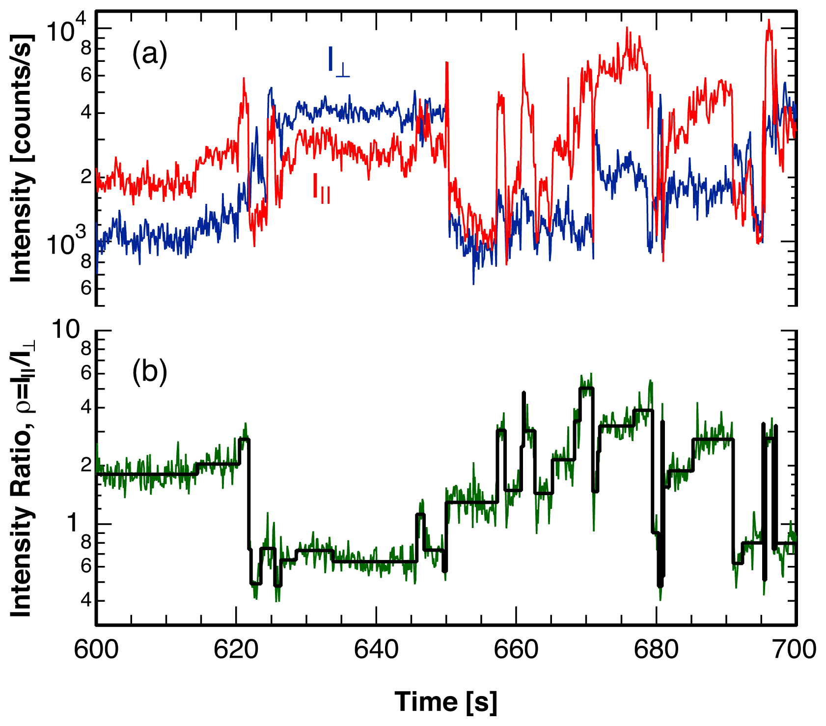
3. Single Molecule Experiment
4. Analysis Method
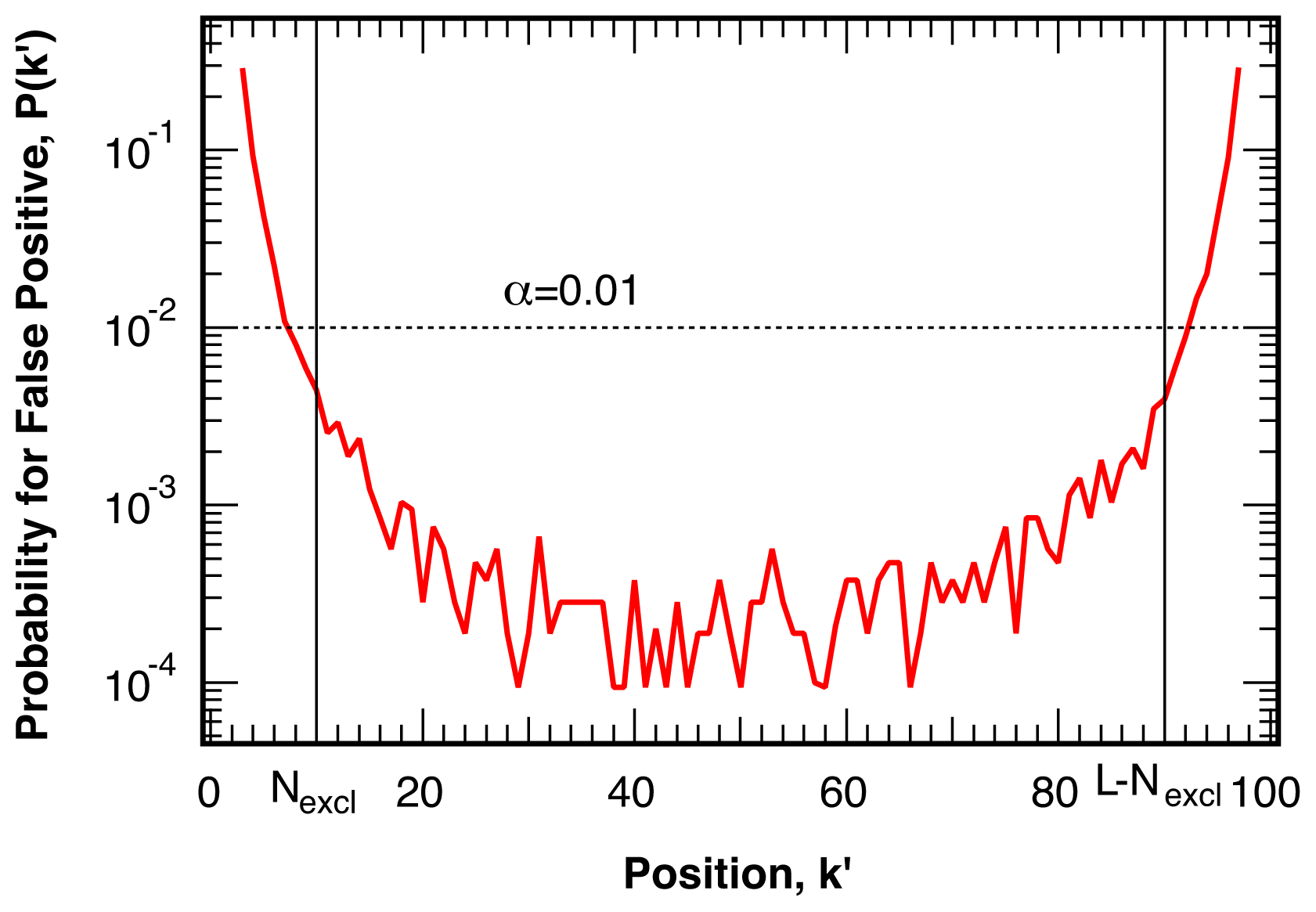
4.1. False Positives
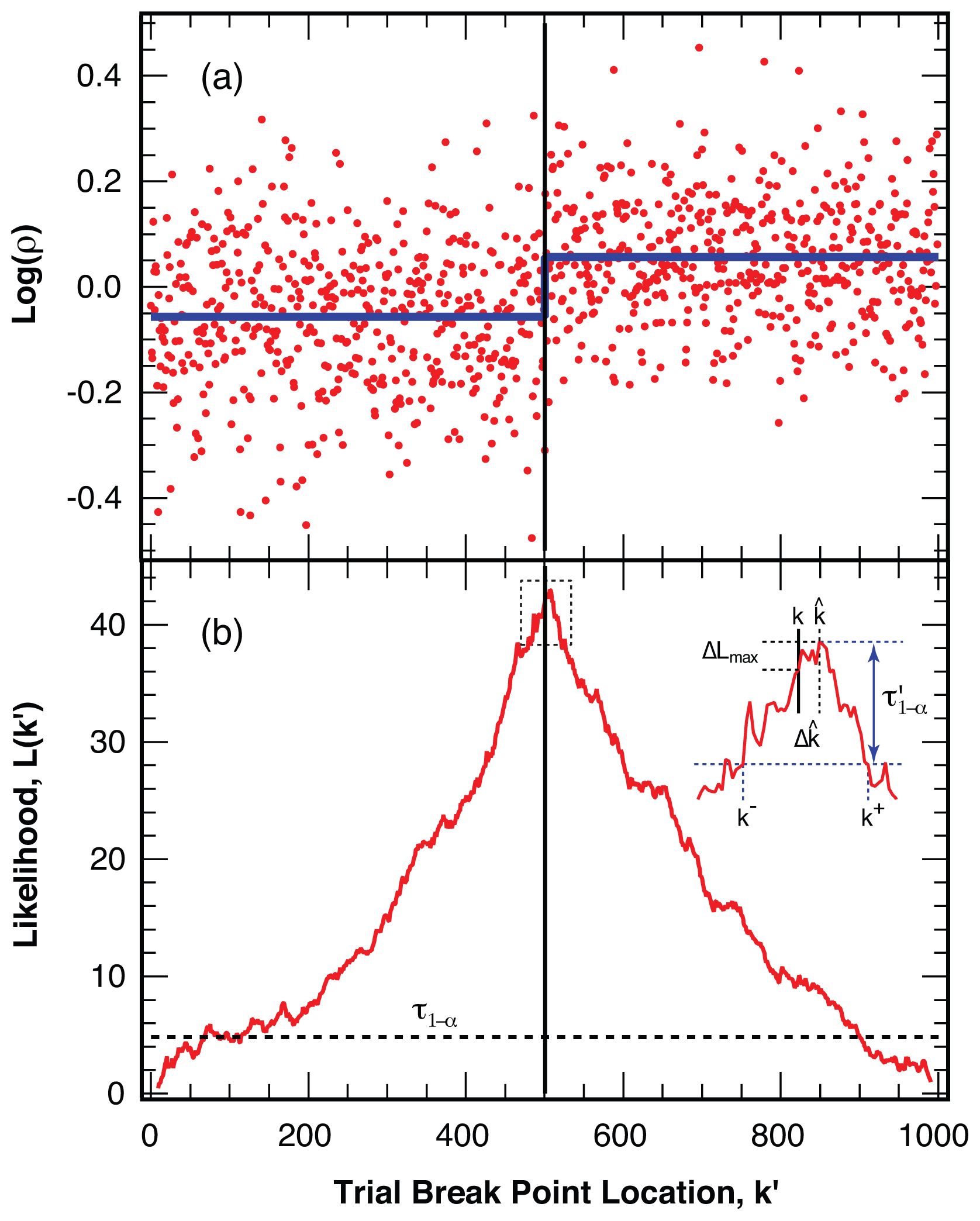
4.2. Location of Break Points
4.3. False Negatives and Error of Location Estimate
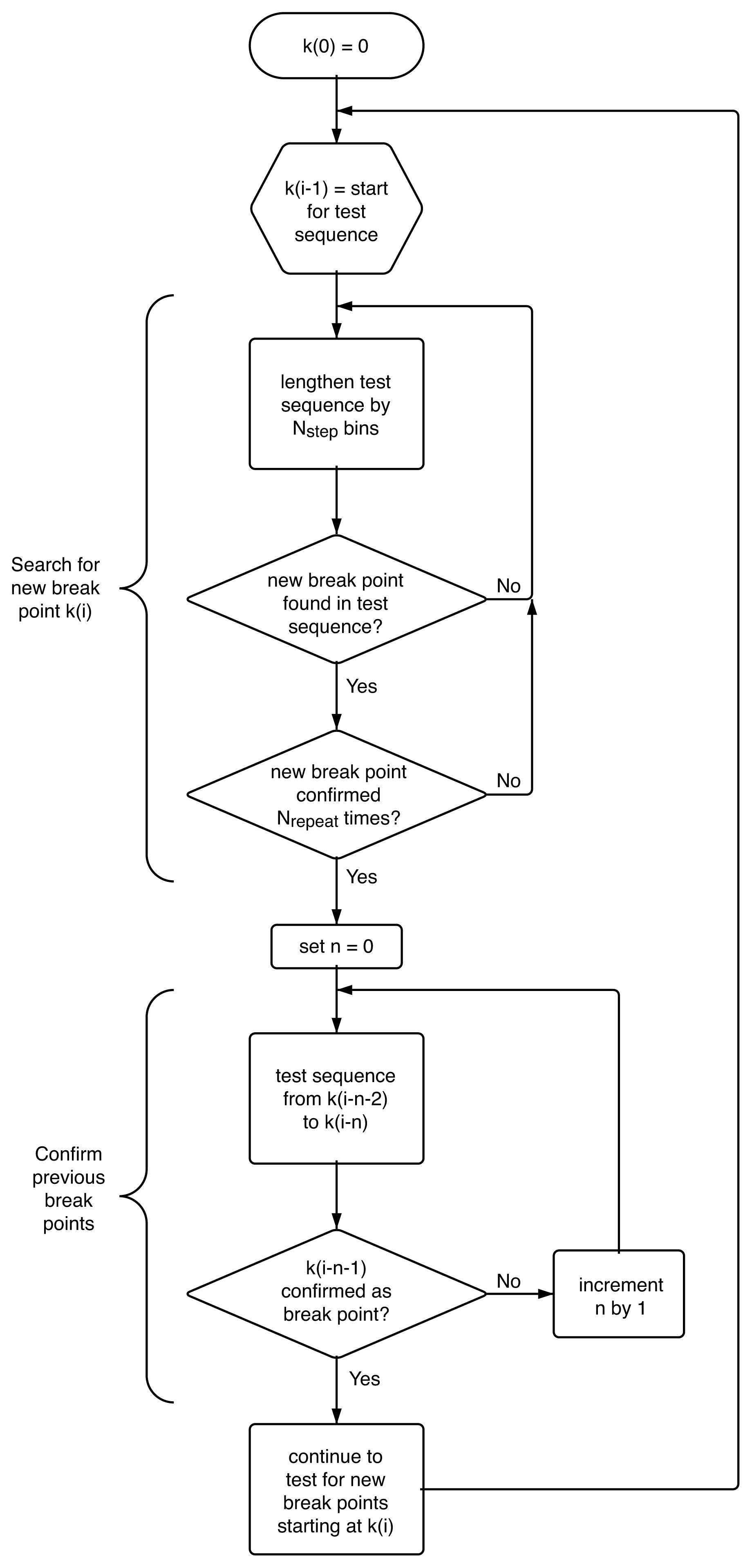
4.4. Algorithm
4.5. Simulation of Photon Sequences With Multiple Break Points
5. Conclusions
Acknowledgements
References
- Plakhotnik, T.; Donley, E.A.; Wild, U.P. Single-molecule spectroscopy. Ann. Rev. Phys. Chem 1997, 48, 181–212. [Google Scholar]
- Weiss, S. Fluorescence spectroscopy of single biomolecules. Science 1999, 283, 1676–1683. [Google Scholar]
- Xie, X.S.; Trautman, J.K. Optical studies of single molecules at room temperature. Ann. Rev. Phys. Chem 1998, 49, 441–480. [Google Scholar]
- Moerner, W.E.; Orrit, M. Illuminating single molecules in condensed matter. Science 1999, 283, 1670–1676. [Google Scholar]
- Moerner, W.E. A dozen years of single-molecule spectroscopy in physics, chemistry, and biophysics. J. Phys. Chem. B 2002, 106, 910–927. [Google Scholar]
- Moerner, W.E. New directions in single-molecule imaging and analysis. Proc. Natl. Acad. Sci. USA 2007, 104, 12596–12602. [Google Scholar]
- Schuler, B. Single-molecule fluorescence spectroscopy of protein folding. ChemPhysChem 2005, 6, 1206–1220. [Google Scholar]
- Tamarat, P.; Maali, A.; Lounis, B.; Orrit, M. Ten years of single-molecule spectroscopy. J. Phys. Chem. A 2000, 104, 1–16. [Google Scholar]
- Bingemann, D. Analysis of ‘blinking’ or ‘hopping’ single molecule signals with a limited number of transitions. Chem. Phys. Lett 2006, 433, 234–238. [Google Scholar]
- Yang, H.; Xie, X.S. Probing single-molecule dynamics photon by photon. J. Chem. Phys 2002, 117, 10965–10979. [Google Scholar]
- Hinze, G.; Basche, T. Statistical analysis of time resolved single molecule fluorescence data without time binning. J. Chem. Phys 2010, 132, 044509:1–044509:6. [Google Scholar]
- Ha, T.; Enderle, T.; Chemla, D.S.; Selvin, P.R.; Weiss, S. Quantum jumps of single molecules at room temperature. Chem. Phys. Lett 1997, 271, 1–5. [Google Scholar]
- Basche, T. Fluorescence intensity fluctuations of single atoms, molecules and nanoparticles. J. Lumin 1998, 76–7, 263–269. [Google Scholar]
- Ishitobi, H.; Kai, T.; Fujita, K.; Sekkat, Z.; Kawata, S. On fluorescence blinking of single molecules in polymers. Chem. Phys. Lett 2009, 468, 234–238. [Google Scholar]
- Heilemann, M.; Margeat, E.; Kasper, R.; Sauer, M.; Tinnefeld, P. Carbocyanine dyes as efficient reversible single-molecule optical switch. J. Am. Chem. Soc 2005, 127, 3801–3806. [Google Scholar]
- Biebricher, A.; Sauer, M.; Tinnefeld, P. Radiative and nonradiative rate fluctuations of single colloidal semiconductor nanocrystals. J. Phys. Chem. B 2006, 110, 5174–5178. [Google Scholar]
- Nirmal, M.; Dabbousi, B.O.; Bawendi, M.G.; Macklin, J.J.; Trautman, J.K.; Harris, T.D.; Brus, L.E. Fluorescence intermittency in single cadmium selenide nanocrystals. Nature 1996, 383, 802–804. [Google Scholar]
- Shimizu, K.T.; Neuhauser, R.G.; Leatherdale, C.A.; Empedocles, S.A.; Woo, W.K.; Bawendi, M.G. Blinking statistics in single semiconductor nanocrystal quantum dots. Phys. Rev. B 2001, 63, 205316:1–205316:5. [Google Scholar]
- Kuno, M.; Fromm, D.P.; Hamann, H.F.; Gallagher, A.; Nesbitt, D.J. Nonexponential “blinking” kinetics of single CdSe quantum dots: A universal power law behavior. J. Chem. Phys 2000, 112, 3117–3120. [Google Scholar]
- Gensch, T.; Bohmer, M.; Aramendia, P.F. Single molecule blinking and photobleaching separated by wide-field fluorescence microscopy. J. Phys. Chem. A 2005, 109, 6652–6658. [Google Scholar]
- Haase, M.; Hubner, C.G.; Reuther, E.; Herrmann, A.; Mullen, K.; Basche, T. Exponential and power-law kinetics in single-molecule fluorescence intermittency. J. Phys. Chem. B 2004, 108, 10445–10450. [Google Scholar]
- Andrec, M.; Levy, R.M.; Talaga, D.S. Direct determination of kinetic rates from single-molecule photon arrival trajectories using hidden markov models. J. Phys. Chem. A 2003, 107, 7454–7464. [Google Scholar]
- Schenter, G.K.; Lu, H.P.; Xie, X.S. Statistical analyses and theoretical models of single-molecule enzymatic dynamics. J. Phys. Chem. A 1999, 103, 10477–10488. [Google Scholar]
- Jung, S.; Dickson, R.M. Hidden markov analysis of short single molecule intensity trajectories. J. Phys. Chem. B 2009, 113, 13886–13890. [Google Scholar]
- Hajdziona, M.; Molski, A. Estimation of single-molecule blinking parameters using photon counting histogram. Chem. Phys. Lett 2009, 470, 363–366. [Google Scholar]
- Burzykowski, T.; Szubiakowski, J.; Ryden, T. Analysis of photon count data from single-molecule fluorescence experiments. Chem. Phys 2003, 288, 291–307. [Google Scholar]
- Jager, M.; Kiel, A.; Herten, D.P.; Hamprecht, F.A. Analysis of single-molecule fluorescence spectroscopic data with a markov-modulated poisson process. Chemphyschem 2009, 10, 2486–2495. [Google Scholar]
- Zhang, K.; Chang, H.; Fu, A.; Alivisatos, A.P.; Yang, H. Continuous distribution of emission states from single CdSe/ZnS quantum dots. Nano Lett 2006, 6, 843–847. [Google Scholar]
- Watkins, L.P.; Yang, H. Detection of intensity change points in time-resolved single-molecule measurements. J. Phys. Chem. B 2005, 109, 617–628. [Google Scholar]
- Kalafut, B.; Visscher, K. An objective, model-independent method for detection of non-uniform steps in noisy signals. Comput. Phys. Commun 2008, 179, 716–723. [Google Scholar]
- Ensign, D.L.; Pande, V.S. Bayesian detection of intensity changes in single molecule and molecular dynamics trajectories. J. Phys. Chem. B 2010, 114, 280–292. [Google Scholar]
- Lu, H.P.; Xun, L.Y.; Xie, X.S. Single-molecule enzymatic dynamics. Science 1998, 282, 1877–1882. [Google Scholar]
- Carter, N.J.; Cross, R.A. Mechanics of the kinesin step. Nature 2005, 435, 308–312. [Google Scholar]
- Empedocles, S.A.; Norris, D.J.; Bawendi, M.G. Photoluminescence spectroscopy of single CdSe nanocrystallite quantum dots. Phys. Rev. Lett 1996, 77, 3873–3876. [Google Scholar]
- Berezin, M.Y.; Achilefu, S. Fluorescence lifetime measurements and biological imaging. Chem. Rev 2010, 110, 2641–2684. [Google Scholar]
- Deniz, A.A.; Laurence, T.A.; Dahan, M.; Chemla, D.S.; Schultz, P.G.; Weiss, S. Ratiometric single-molecule studies of freely diffusing biomolecules. Ann. Rev. Phys. Chem 2001, 52, 233–253. [Google Scholar]
- Rosenberg, S.A.; Quinlan, M.E.; Forkey, J.N.; Goldman, Y.E. Rotational motions of macro-molecules by single-molecule fluorescence microscopy. Acc. Chem. Res 2005, 38, 583–593. [Google Scholar]
- Bingemann, D.; Allen, R.; Olesen, S. Single molecules reveal the dynamics of heterogeneities in a polymer at the glass transition. J. Chem. Phys 2011, 134, 024513:1–024513:9. [Google Scholar]
- Adhikari, S.; Selmke, M.; Cichos, F. Temperature dependent single molecule rotational dynamics in PMA. Phys. Chem. Chem. Phys 2011, 13, 1849–1856. [Google Scholar]
- Hu, D.; Lu, H.P. Single-molecule nanosecond anisotropy dynamics of tethered protein motions. J. Phys. Chem. B 2002, 107, 618–626. [Google Scholar]
- Prummer, M.; Sick, B.; Renn, A.; Wild, U.P. Multiparameter microscopy and spectroscopy for single-molecule analytics. Anal. Chem 2004, 76, 1633–1640. [Google Scholar]
- Lu, H.P. Probing single-molecule protein conformational dynamics. Acc. Chem. Res 2005, 38, 557–565. [Google Scholar]
- Yuan, H.; Xia, T.; Schuler, B.; Orrit, M. Temperature-cycle single-molecule FRET microscopy on polyprolines. Phys. Chem. Chem. Phys 2011, 13, 1762–1769. [Google Scholar]
- Chung, H.S.; Gopich, I.V.; McHale, K.; Cellmer, T.; Louis, J.M.; Eaton, W.A. Extracting rate coefficients from single-molecule photon trajectories and fret efficiency histograms for a fast-folding protein. J.Phys. Chem. A 2010, 115, 3642–3656. [Google Scholar]
- Jameson, D.M.; Ross, J.A. Fluorescence polarization/anisotropy in diagnostics and imaging. Chem. Rev 2010, 110, 2685–2708. [Google Scholar]
- Gopich, I.V.; Szabo, A. Decoding the pattern of photon colors in single-molecule FRET. J. Phys. Chem. B 2009, 113, 10965–10973. [Google Scholar]
- Xu, C.S.; Kim, H.; Hayden, C.C.; Yang, H. Joint statistical analysis of multichannel time series from single quantum dot-(Cy5)n constructs. J. Phys. Chem. B 2008, 112, 5917–5923. [Google Scholar]
- Adhikari, A.; Capurso, N.; Bingemann, D. Heterogeneous dynamics and dynamic heterogeneities at the glass transition probed with single molecule spectroscopy. J. Chem. Phys 2007, 127, 027732:1–027732:9. [Google Scholar]
- Vallee, R.A.L.; Tomczak, N.; Vancso, G.J.; Kuipers, L.; van Hulst, N.F. Fluorescence lifetime fluctuations of single molecules probe local density fluctuations in disordered media: A bulk approach. J. Chem. Phys 2005, 122, 114704. [Google Scholar]
- Teschke, O.; Dienes, A.; Holtom, G. Measurement of triplet lifetime in a jet stream cw dye laser. Opt. Commun 1975, 13, 318–320. [Google Scholar]
- Clarke, R.W.; Orte, A.; Klenerman, D. Optimized threshold selection for single-molecule two-color fluorescence coincidence spectroscopy. Anal. Chem 2007, 79, 2771–2777. [Google Scholar]
- Widengren, J.; Kudryavtsev, V.; Antonik, M.; Berger, S.; Gerken, M.; Seidel, C.A.M. Single-molecule detection and identification of multiple species by multiparameter fluorescence detection. Anal. Chem 2006, 78, 2039–2050. [Google Scholar]
- Press, W.H.; Teukolsky, S.A.; Vetterling, W.T.; Flannery, B.P. Numerical Recipes in C: The Art of Scientific Computing; Cambridge University Press: Cambridge, UK, 1992. [Google Scholar]
- Fourkas, J.T. Rapid determination of the three-dimensional orientation of single molecules. Opt. Lett 2001, 26, 211–213. [Google Scholar]


| Nominal Confidence, 1 − α | Effective Confidence, 1 − αeff | Amplitude, A | scale, s | Exponent, λ |
|---|---|---|---|---|
| 90% | 98% | 3.62 | 0.565 | 0.285 |
| 95% | 99% | 4.15 | 0.567 | 0.249 |
| 98% | 99.8% | 4.98 | 0.580 | 0.227 |
| 99% | 99.95% | 5.79 | 0.608 | 0.231 |
| 99.5% | 99.98% | 6.80 | 0.655 | 0.253 |
| confidence, 1 − α | small max/L constant threshold, τ′0 | amplitude, A | exponent, λ |
|---|---|---|---|
| 68% | 1.10 | 27 | 1.15 |
| 90% | 1.95 | 34 | 1.12 |
| 95% | 2.65 | 37 | 1.15 |
| 98% | 3.40 | 41 | 1.15 |
| 99% | 4.20 | 43 | 1.15 |
| 99.5% | 5.20 | 45 | 1.18 |
© 2012 by the authors; licensee Molecular Diversity Preservation International, Basel, Switzerland. This article is an open-access article distributed under the terms and conditions of the Creative Commons Attribution license (http://creativecommons.org/licenses/by/3.0/).
Share and Cite
Bingemann, D.; Allen, R.M. Identification of Intensity Ratio Break Points from Photon Arrival Trajectories in Ratiometric Single Molecule Spectroscopy. Int. J. Mol. Sci. 2012, 13, 7445-7465. https://doi.org/10.3390/ijms13067445
Bingemann D, Allen RM. Identification of Intensity Ratio Break Points from Photon Arrival Trajectories in Ratiometric Single Molecule Spectroscopy. International Journal of Molecular Sciences. 2012; 13(6):7445-7465. https://doi.org/10.3390/ijms13067445
Chicago/Turabian StyleBingemann, Dieter, and Rachel M. Allen. 2012. "Identification of Intensity Ratio Break Points from Photon Arrival Trajectories in Ratiometric Single Molecule Spectroscopy" International Journal of Molecular Sciences 13, no. 6: 7445-7465. https://doi.org/10.3390/ijms13067445
APA StyleBingemann, D., & Allen, R. M. (2012). Identification of Intensity Ratio Break Points from Photon Arrival Trajectories in Ratiometric Single Molecule Spectroscopy. International Journal of Molecular Sciences, 13(6), 7445-7465. https://doi.org/10.3390/ijms13067445