Combined 3D-QSAR Modeling and Molecular Docking Studies on Pyrrole-Indolin-2-ones as Aurora A Kinase Inhibitors

Abstract
:1. Introduction
2. Materials and Methods
2.1. Data Sets
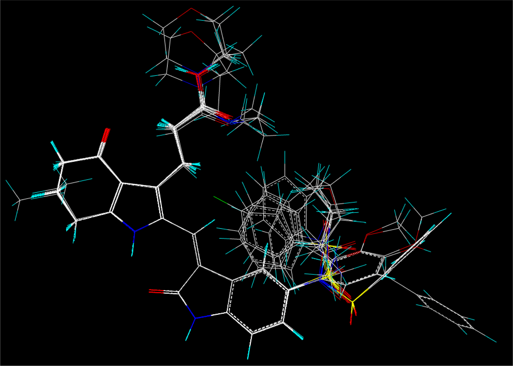
2.2. Molecular Modeling and Database Alignment
2.3. CoMFA and CoMSIA Setup
2.4. Regression Analysis and Models Validation
2.5. Predictive Correlation Co-efficient (r2pred)
2.6. Molecular Docking
3. Results and Discussions
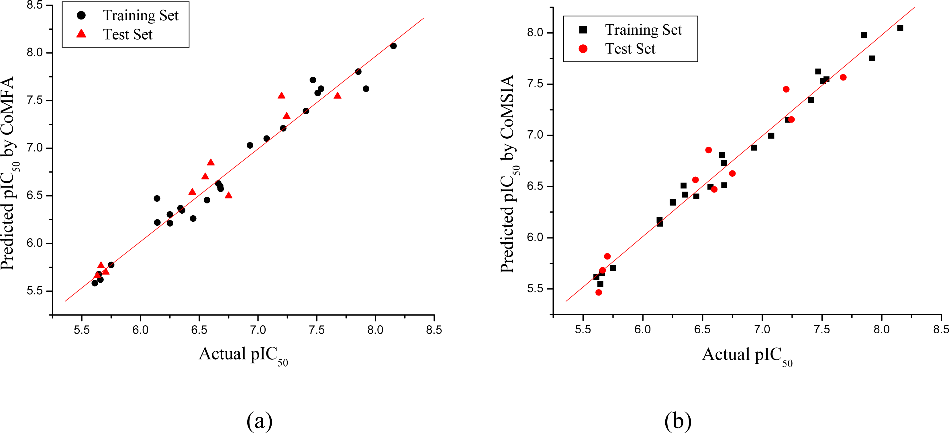
3.1. CoMFA and CoMSIA Models
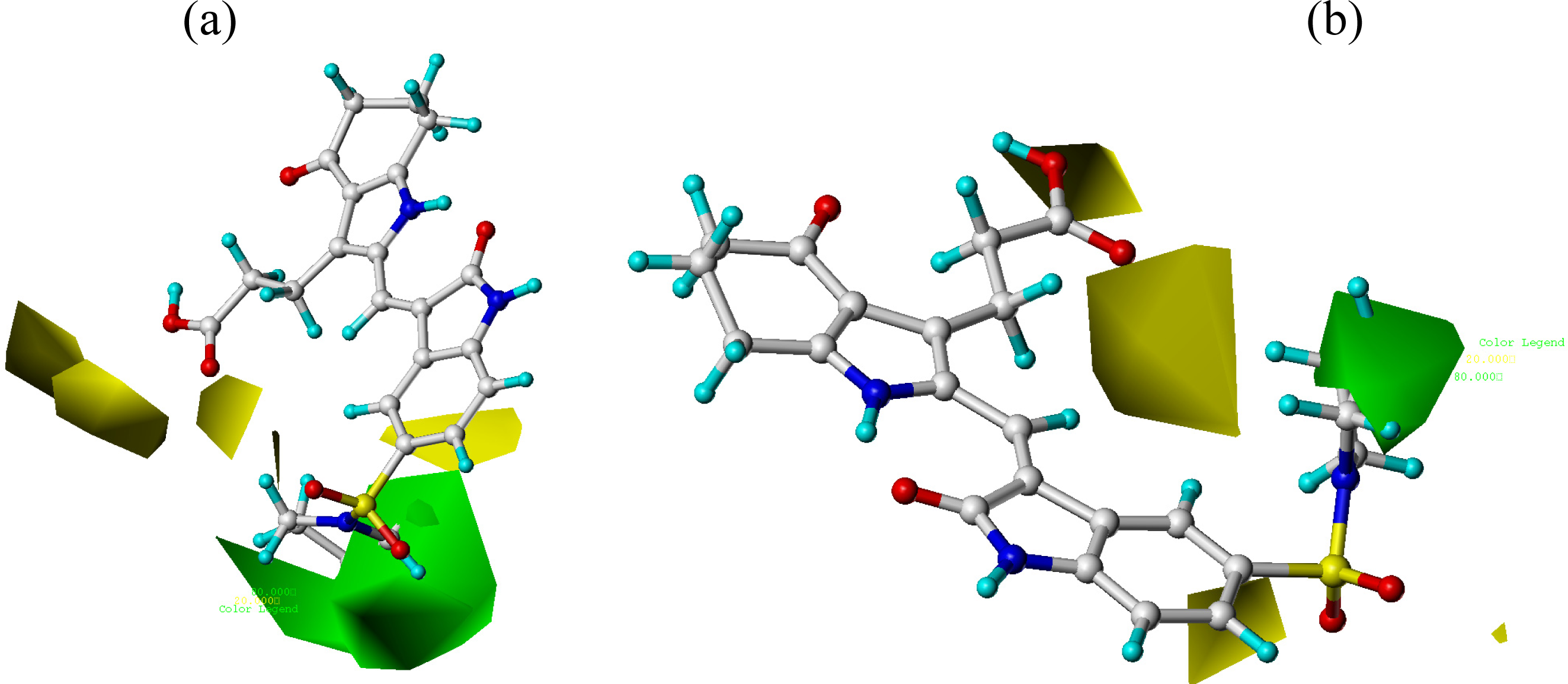
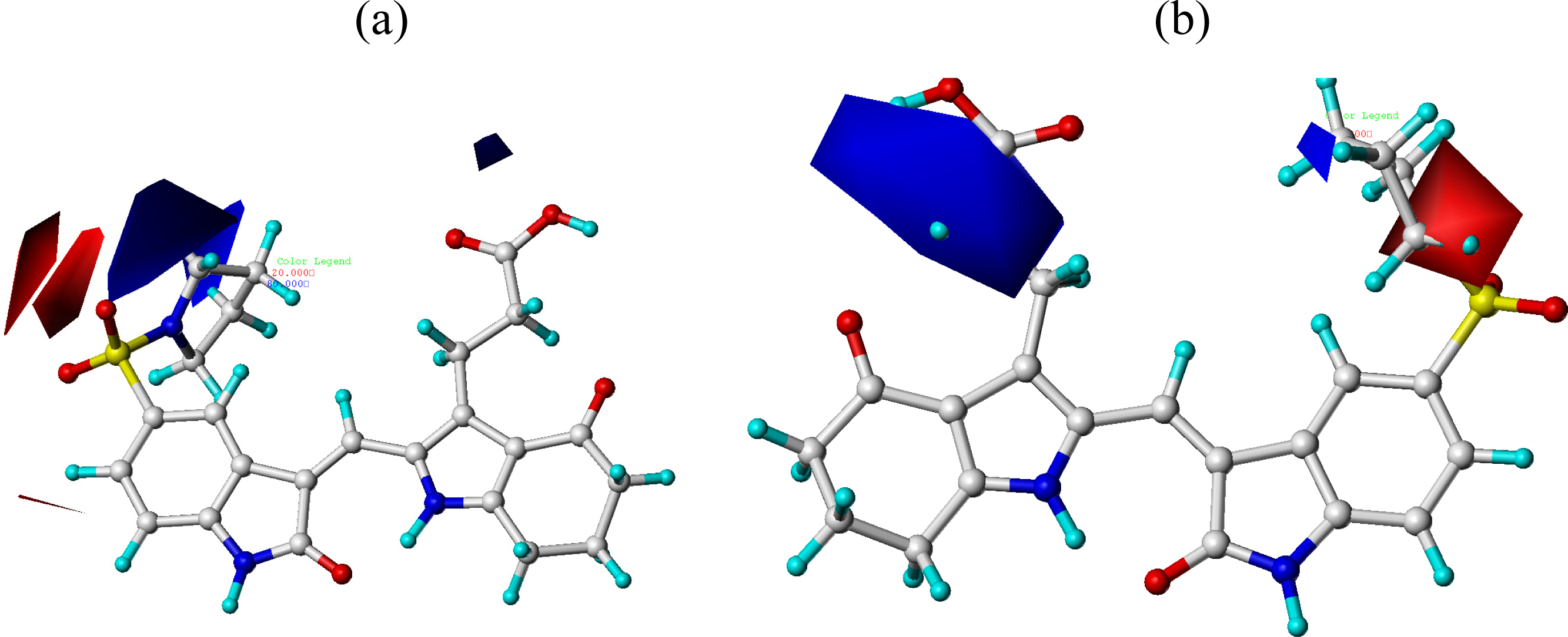
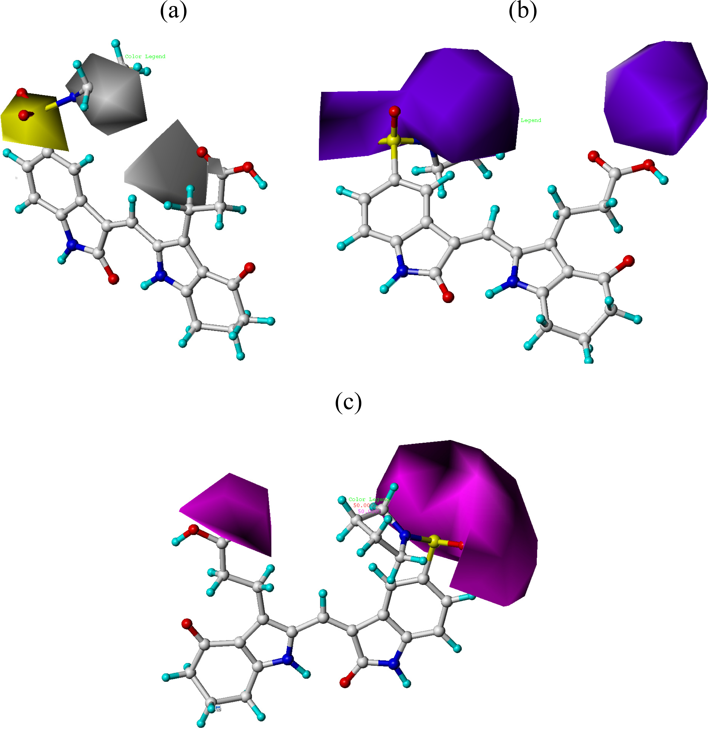
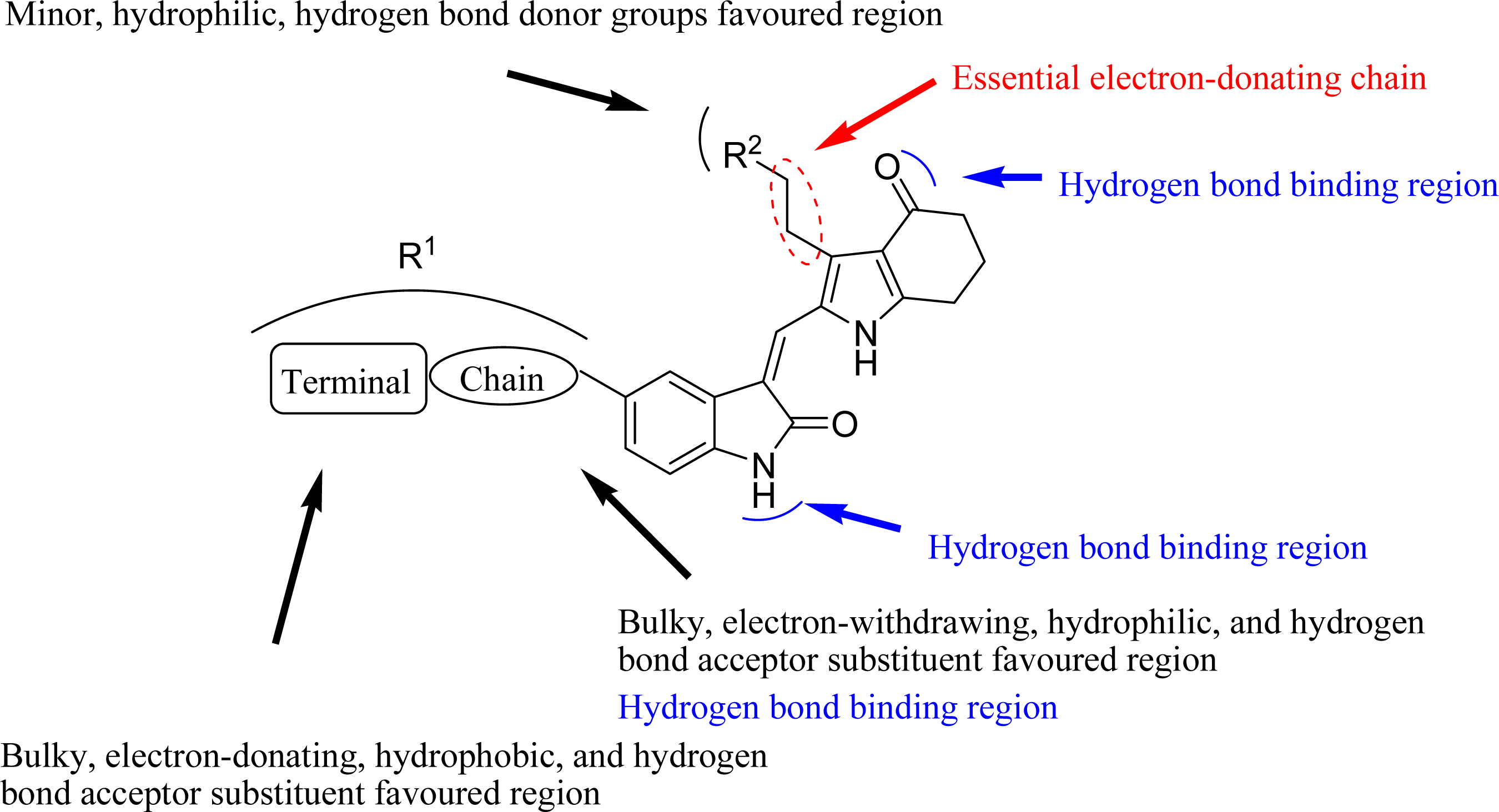
3.2. CoMFA and CoMSIA Contour Maps
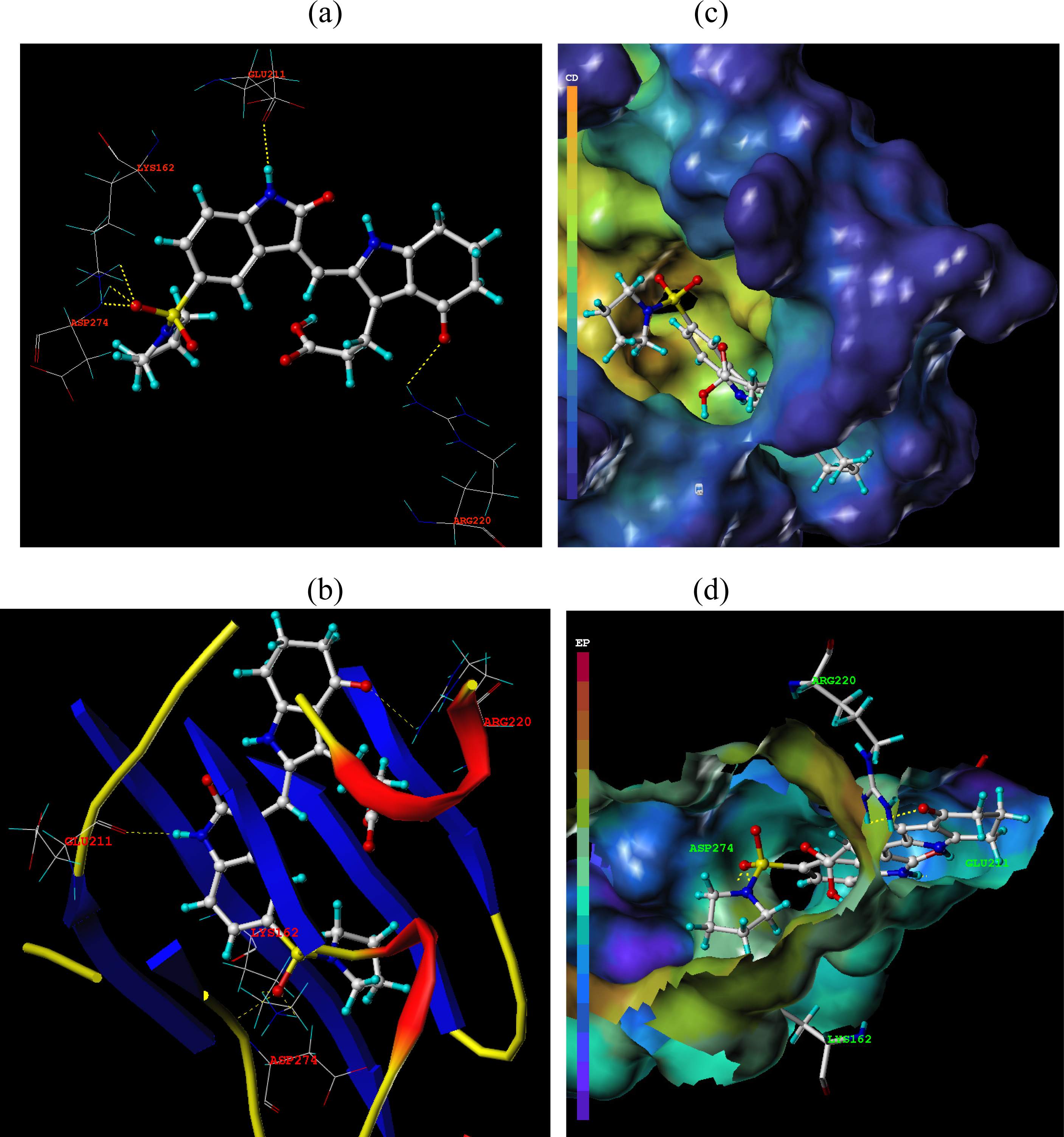
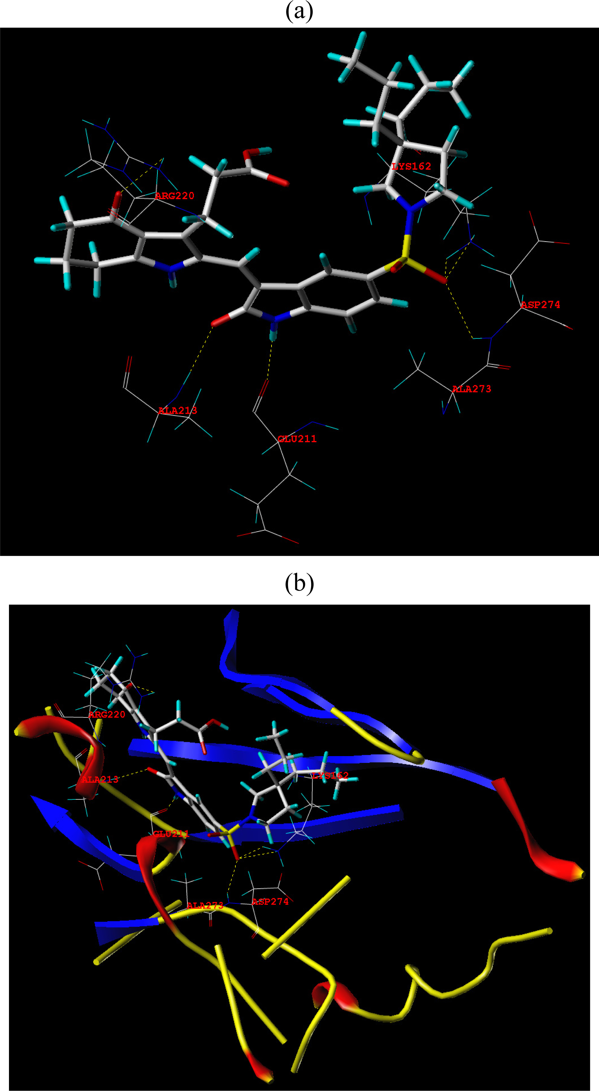
3.3. Docking Analysis
3.4. Design for New Molecules
4. Conclusion
Acknowledgments
References
- Ando, R; Ikegami, H; Sakiyama, M; Ooike, S; Hayashi, M; Fujino, Y; Abe, D; Nakamura, H; Mishina, T; Kato, H; Iwase, Y; Tomozane, H; Morioka, M. 3-Cyano-6-(5-methyl-3-pyrazoloamino)pyridines: Selective Aurora A kinase inhibitors. Bioorg. Med. Chem. Lett 2010, 20, 4709–4711. [Google Scholar]
- Cee, VJ; Schenkel, LB; Hodous, BL; Deak, HL; Nguyen, HN; Olivieri, PR; Romero, R; Bak, A; Be, X; Bellon, S; Bush, TL; Cheng, AC; Chuang, G; Coats, S; Eden, PM; Hanestad, K; Gallant, PL; Gu, Y; Huang, X; Kendall, RL; Lin, MHJ; Morrison, MJ; Patel, VF; Radinsky, R; Rose, PE; Ross, S; Sun, JR; Tang, J; Zhao, H; Payton, M; Geuns-Meyer, SD. Discovery of a potent, selective, and orally bioavailable pyridinyl-pyrimidine phthalazine Aurora kinase inhibitor. J. Med. Chem 2010, 53, 6368–6377. [Google Scholar]
- Kishore, AH; Vedamurthy, BM; Mantelingu, K; Agrawal, S; Ashok Reddy, BA; Roy, S; Rangappa, KS; Kundu, TK. Specific Small-Molecule Activator of Aurora Kinase A Induces Autophosphorylation in a Cell-Free System. J. Med. Chem 2008, 51, 792–797. [Google Scholar]
- Rawson, TE; Rüth, M; Blackwood, El; Burdick, D; Corson, L; Dotson, J; Drummond, J; Fields, C; Georges, GJ; Goller, B; Halladay, J; Hunsaker, T; Kleinheinz, T; Krell, HW; Li, J; Liang, J; Limberg, A; McNutt, A; Moffat, J; Phillips, G; Ran, YQ; Safina, B; Ultsch, M; Walker, L; Wiesmann, C; Zhang, B; Zhou, A; Zhu, BY; Rüger, P; Cochran,, AG. A Pentacyclic Aurora Kinase Inhibitor (AKI-001) with High in Vivo Potency and Oral Bioavailability. J. Med. Chem 2008, 51, 4465–4475. [Google Scholar]
- Coumar, MS; Chu, CY; Lin, CW; Shiao, HY; Ho, YL; Reddy, R; Lin, WH; Chen, CH; Peng, YH; Leou, JS; Lien, TW; Huang, CT; Fang, MY; Wu, SH; Wu, JS; Chittimalla, SK; Song, JS; Hsu, JTA; Wu, SY; Liao, CC; Chao, YS; Hsieh, HP. Fast-Forwarding Hit to Lead: Aurora and Epidermal Growth Factor Receptor Kinase Inhibitor Lead Identification. J. Med. Chem 2010, 53, 4980–4988. [Google Scholar]
- Aliagas-Martin, I; Burdick, D; Corson, L; Dotson, J; Drummond, J; Fields, C; Huang, OW; Hunsaker, T; Kleinheinz, T; Krueger, E; Liang, J; Moffat, J; Phillips, G; Pulk, R; Rawson, TE; Ultsch, M; Walker, L; Wiesmann, C; Zhang, B; Zhu, BY; Cochran, AG. A Class of 2,4-Bisanilinopyrimidine Aurora A Inhibitors with Unusually High Selectivity against Aurora B. J. Med. Chem 2009, 52, 3300–3307. [Google Scholar]
- Coumar, MS; Leou, JS; Shukla, P; Wu, JS; Dixit, AK; Lin, WH; Chang, CY; Lien, TW; Tan, UK; Chen, CH; Hsu, JTA; Chao, YS; Wu, SY; Hsieh, HP. Structure-Based Drug Design of Novel Aurora Kinase A Inhibitors: Structural Basis for Potency and Specificity. J. Med. Chem 2009, 52, 1050–1062. [Google Scholar]
- Bavetsias, V; Large, JM; Sun, C; Bouloc, N; Kosmopoulou, M; Matteucci, M; Wilsher, NE; Martins, V; Reynisson, J; Atrash, B; Faisal, A; Urban, F; Valenti, M; Brandon, ADH; Box, G; Raynaud, FI; Workman, P; Eccles, SA; Bayliss, R; Blagg, J; Linardopoulos, S; McDonald, E. Imidazo[4,5-b]pyridine Derivatives As Inhibitors of Aurora Kinases: Lead Optimization Studies toward the Identification of an Orally Bioavailable Preclinical Development Candidate. J. Med. Chem 2010, 53, 5213–5228. [Google Scholar]
- Wang, SD; Midgley, CA; Scaërou, F; Grabarek, JB; Griffiths, G; Jackson, W; Kontopidis, G; McClue, SJ; McInnes, C; Meades, C; Mezna, M; Plater, A; Stuart, I; Thomas, MP; Wood, G; Clarke, RG; Blake, DG; Zheleva, DI; Lane, DP; Jackson, RC; Glover, DM; Fischer, PM. Discovery of N-Phenyl-4-(thiazol-5-yl)pyrimidin-2-amine Aurora Kinase Inhibitors. J. Med. Chem 2010, 53, 4367–4378. [Google Scholar]
- Bouloc, N; Large, JM; Kosmopoulou, M; Sun, C; Faisal, A; Matteucci, M; Reynisson, J; Brown, N; Atrash, B; Blagg, J; McDonald, E; Linardopoulos, S; Bayliss, R; Bavetsias, V. Structure-based design of imidazo[1,2-a]pyrazine derivatives as selective inhibitors of Aurora-A kinase in cells. Bioorg. Medi. Chem. Lett 2010, 20, 5988–5993. [Google Scholar]
- Pollard, JR; Mortimore, M. Discovery and Development of Aurora Kinase Inhibitors as Anticancer Agents. J. Med. Chem 2009, 52, 2629–2651. [Google Scholar]
- Howard, S; Berdini, V; Boulstridge, JA; Carr, MG; Cross, DM; Curry, J; Devine, LA; Early, TR; Fazal, L; Gill, AL; Heathcote, M; Maman, S; Matthews, JE; McMenamin, RL; Navarro, EF; O’Brien, MA; O’Reilly, M; Rees, DC; Reule, M; Tisi, D; Williams, G; Vinković, M; Wyatt, PG. Fragment-Based Discovery of the Pyrazol-4-yl Urea (AT9283), a Multitargeted Kinase Inhibitor with Potent Aurora Kinase Activity. J. Med. Chem 2009, 52, 379–388. [Google Scholar]
- Chiang, CC; Lin, YH; Lin, SF; Lai, CL; Liu, C; Wei, WY; Yang, SV; Wang, RW; Teng, LW; Chuang, SH; Chang, JM; Yuan, TT; Lee, YS; Chen, P; Chi, WK; Yang, JY; Huang, HJ; Liao, CB; Huang, JJ. Discovery of Pyrrole-Indoline-2-ones as Aurora Kinase Inhibitors with a Different Inhibition Profile. J. Med. Chem 2010, 53, 5929–5941. [Google Scholar]
- Hauf, S; Cole, RW; LaTerra, S; Zimmer, C; Schnapp, G; Walter, R; Heckel, A; van Meel, J; Rieder, CL; Peters, J-M. The small molecule Hesperadin reveals a role for Aurora B in correcting kinetochore-microtubule attachment and in maintaining the spindle assembly checkpoint. J. Cell Biol 2003, 161, 281–294. [Google Scholar]
- Cichero, E; Cesarini, S; Spallarossa, A; Mosti, L; Fossa, P. Computational studies of the binding mode and 3D-QSAR analyses of symmetric formimidoester disulfides: A new class of non-nucleoside HIV-1 reverse transcriptase inhibitor. J. Mol. Model 2009, 15, 357–367. [Google Scholar]
- Sybyl 8.1; Tripos Inc: St. Louis, MO, USA, 2008. Available online: http://www.tripos.com (accessed on 26 January 2011).
- Sun, J; Cai, S; Yan, N; Mei, H. Docking and 3D-QSAR studies of influenza neuraminidase inhibitors using three-dimensional holographic vector of atomic interaction field analysis. Eur. J. Med. Chem 2010, 45, 1008–1014. [Google Scholar]
- Wellsow, J; Machullab, HJ; Kovar, KA. 3D QSAR of serotonin transporter ligands: CoMFA and CoMSIA studies. Quant. Struct.-Act. Relatsh 2002, 21, 577–589. [Google Scholar]
- Liu, HY; Liu, SS; Qin, LT; Mo, LY. CoMFA and CoMSIA analysis of 2,4-thiazolidinediones derivatives as aldose reductase inhibitors. J. Mol. Model 2009, 15, 837–845. [Google Scholar]
- Ai, Y; Wang, ST; Sun, PH; Song, FJ. Molecular Modeling Studies of 4,5-Dihydro-1H-pyrazolo[4,3-h] quinazoline Derivatives as Potent CDK2/Cyclin A Inhibitors Using 3D-QSAR and Docking. Int. J. Mol. Sci 2010, 11, 3705–3724. [Google Scholar]
- Lan, P; Chen, WN; Chen, WM. Molecular modeling studies on imidazo[4,5-b]pyridine derivatives as Aurora A kinase inhibitors using 3D-QSAR and docking approaches. Eur. J. Med. Chem 2011, 46, 77–94. [Google Scholar]
- Lan, P; Chen, WN; Xiao, GK; Sun, PH; Chen, WM. 3D-QSAR and docking studies on pyrazolo[4,3-h]quinazoline-3-carboxamides as cyclin-dependent kinase 2 (CDK2) inhibitors. Bioorg. Med. Chem. Lett 2010, 20, 6764–6772. [Google Scholar]
- Pan, X; Tan, N; Zeng, G; Huang, H; Yan, H. 3D QSAR studies on ketoamides of human cathepsin K inhibitors based on two different alignment methods. Eur. J. Med. Chem 2010, 45, 667–681. [Google Scholar]
- Cichero, E; Cesarini, S; Mosti, L; Fossa, P. CoMFA and CoMSIA analyses on 4-oxo-1,4-dihydroquinoline and 4-oxo-1,4-dihydro-1,5-,-1,6- and -1,8-naphthyridine derivatives as selective CB2 receptor agonists. J. Mol. Model 2010, 16, 677–691. [Google Scholar]
- Yang, ZQ; Sun, PH. 3D-QSAR study of potent inhibitors of phosphodiesterase-4 using a CoMFA approach. Int. J. Mol. Sci 2007, 8, 714–722. [Google Scholar]
- Jain, AN. Surflex: Fully automatic flexible molecular docking using a molecular Similarity-Based search engine. J. Med. Chem 2003, 46, 499–511. [Google Scholar]
- Sun, JY; Cai, SX; Mei, H; Li, J; Yan, N; Wang, YQ. Docking and 3D-QSAR study of thiourea analogs as potent inhibitors of influenza virus neuraminidase. J. Mol. Model 2010, 16, 1809–1818. [Google Scholar]


 | ||
|---|---|---|
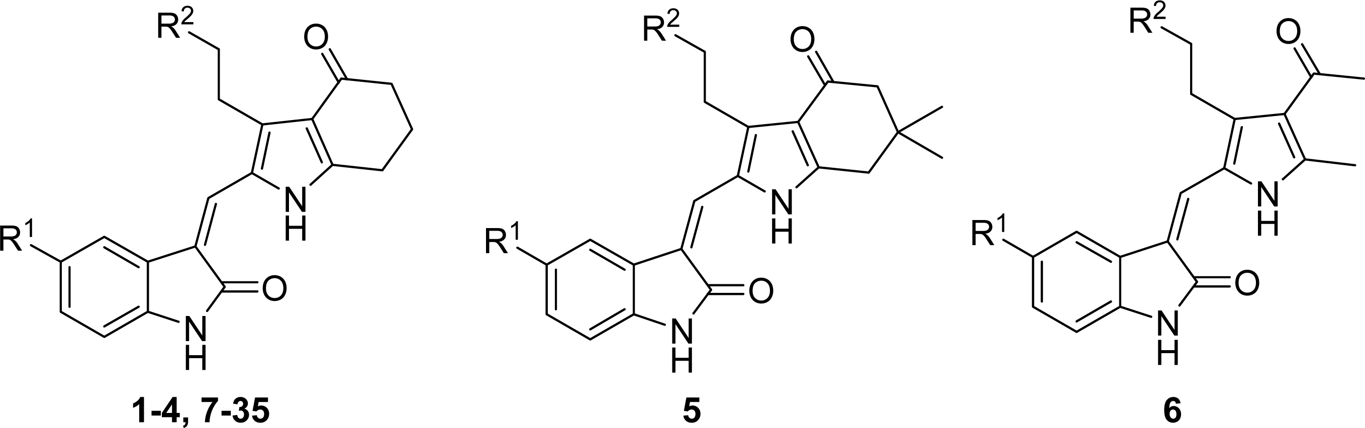
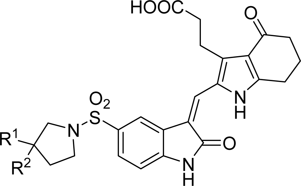
| Compound No. | Substituent | |
| R1 | R2 | |
| 1 | H | COOEt |
| 2 | F | COOEt |
| 3 | H | COOH |
| 4 | F | COOH |
| 5 | F | COOH |
| 6 | F | COOH |
| 7 | Br | COOH |
| 8 | NO2 | COOH |
| 9 |  | COOH |
| 10 |  | COOH |
| 11 |  | COOH |
| 12 |  | COOH |
| 13 |  | COOH |
| 14 |  | COOH |
| 15 |  | COOH |
| 16 |  | COOH |
| 17 |  | COOH |
| 18 |  | COOH |
| 19 |  | COOH |
| 20 |  | COOH |
| 21 |  | COOH |
| 22 |  | COOH |
| 23 |  | COOH |
| 24 |  | COOH |
| 25 |  | COOH |
| 26 |  | COOEt |
| 27 |  |  |
| 28 |  |  |
| 29 |  |  |
| 30 |  |  |
| 31 |  |  |
| 32 |  |  |
| 33 |  |  |
| 34 |  |  |
| 35 |  |  |
| Compd. No. | pIC50 | CoMFA | CoMSIA | ||
|---|---|---|---|---|---|
| Actual | Pred. | Res. | Pred. | Res. | |
| 1 | 5.750 | 5.775 | −0.025 | 5.703 | 0.047 |
| 2* | 5.703 | 5.698 | 0.005 | 5.819 | −0.116 |
| 3 | 6.682 | 6.573 | 0.109 | 6.512 | 0.170 |
| 4* | 6.750 | 6.499 | 0.251 | 6.628 | 0.122 |
| 5 | 6.341 | 6.372 | −0.031 | 6.510 | −0.169 |
| 6* | 6.441 | 6.536 | −0.095 | 6.565 | −0.124 |
| 7 | 6.678 | 6.602 | 0.076 | 6.729 | −0.051 |
| 8 | 6.140 | 6.473 | −0.333 | 6.175 | −0.035 |
| 9 | 6.447 | 6.262 | 0.185 | 6.403 | 0.044 |
| 10 | 6.252 | 6.211 | 0.041 | 6.342 | −0.090 |
| 11* | 6.599 | 6.844 | −0.245 | 6.471 | 0.128 |
| 12 | 6.143 | 6.221 | −0.078 | 6.136 | 0.007 |
| 13* | 7.244 | 7.333 | −0.089 | 7.155 | 0.089 |
| 14 | 7.409 | 7.390 | 0.019 | 7.345 | 0.064 |
| 15 | 6.567 | 6.455 | 0.112 | 6.498 | 0.069 |
| 16 | 6.354 | 6.347 | 0.007 | 6.421 | −0.067 |
| 17 | 7.215 | 7.209 | 0.006 | 7.152 | 0.063 |
| 18 | 7.509 | 7.580 | −0.071 | 7.530 | −0.021 |
| 19* | 7.678 | 7.544 | 0.134 | 7.566 | 0.112 |
| 20 | 8.155 | 8.073 | 0.082 | 8.049 | 0.106 |
| 21 | 7.854 | 7.803 | 0.051 | 7.977 | −0.123 |
| 22 | 7.538 | 7.623 | −0.085 | 7.548 | −0.010 |
| 23 | 7.469 | 7.715 | −0.247 | 7.623 | −0.155 |
| 24 | 7.921 | 7.623 | 0.298 | 7.751 | 0.170 |
| 25* | 7.201 | 7.545 | −0.344 | 7.449 | −0.248 |
| 26 | 7.076 | 7.101 | −0.025 | 6.995 | 0.081 |
| 27 | 6.662 | 6.630 | 0.032 | 6.806 | −0.145 |
| 28* | 6.551 | 6.697 | −0.146 | 6.857 | −0.306 |
| 29 | 6.932 | 7.030 | −0.098 | 6.880 | 0.052 |
| 30 | 6.250 | 6.303 | −0.053 | 6.350 | −0.101 |
| 31* | 5.664 | 5.765 | −0.102 | 5.682 | −0.019 |
| 32 | 5.660 | 5.621 | 0.039 | 5.651 | 0.009 |
| 33 | 5.611 | 5.584 | 0.027 | 5.619 | −0.008 |
| 34 | 5.644 | 5.677 | −0.033 | 5.550 | 0.094 |
| 35* | 5.631 | 5.660 | −0.029 | 5.466 | 0.165 |
| Statistics | CoMFA | CoMSIA |
|---|---|---|
| r2cva | 0.726 | 0.566 |
| r2b | 0.972 | 0.984 |
| ONCc | 6 | 6 |
| SEEd | 0.144 | 0.110 |
| F valuee | 105.300 | 181.398 |
| r2predf | 0.937 | 0.948 |
| Field contribution | ||
| Steric | 0.457 | 0.152 |
| Electrostatic | 0.543 | 0.169 |
| Hydrophobic | - | 0.243 |
| H-bond Donor | - | 0.183 |
| H-bond Acceptor | - | 0.252 |
 | |||||
|---|---|---|---|---|---|
| Compound NO. | Substituent | Predicted pIC50 | Total score | ||
| R1 | R2 | CoMFA | CoMSIA | ||
| 20 | H | H | 8.073 | 8.049 | 8.49 |
| D1 | H | C(CH3)3 | 7.822 | 8.095 | 9.09 |
| D2 | H | CH2C(CH3)3 | 7.823 | 8.133 | 10.28 |
| D3 | H | CH2CH2C(CH3)3 | 8.044 | 8.302 | 9.82 |
| D4 | CH3 | CH3 | 8.047 | 8.294 | 8.91 |
| D5 | H | CH3 | 8.091 | 8.203 | 7.60 |
| D6 | CH3 | CH2CH3 | 7.710 | 8.160 | 8.88 |
| D7 | CH2CH3 | CH2CH3 | 7.661 | 8.156 | 9.23 |
| D8 | CH2CH2CH3 | CH2CH2CH3 | 7.647 | 8.145 | 10.46 |
| D9 | CH3 | cyclohexane | 7.633 | 8.154 | 10.32 |
© 2011 by the authors; licensee MDPI, Basel, Switzerland. This article is an open-access article distributed under the terms and conditions of the Creative Commons Attribution license (http://creativecommons.org/licenses/by/3.0/).
Share and Cite
Ai, Y.; Wang, S.-T.; Sun, P.-H.; Song, F.-J. Combined 3D-QSAR Modeling and Molecular Docking Studies on Pyrrole-Indolin-2-ones as Aurora A Kinase Inhibitors. Int. J. Mol. Sci. 2011, 12, 1605-1624. https://doi.org/10.3390/ijms12031605
Ai Y, Wang S-T, Sun P-H, Song F-J. Combined 3D-QSAR Modeling and Molecular Docking Studies on Pyrrole-Indolin-2-ones as Aurora A Kinase Inhibitors. International Journal of Molecular Sciences. 2011; 12(3):1605-1624. https://doi.org/10.3390/ijms12031605
Chicago/Turabian StyleAi, Yong, Shao-Teng Wang, Ping-Hua Sun, and Fa-Jun Song. 2011. "Combined 3D-QSAR Modeling and Molecular Docking Studies on Pyrrole-Indolin-2-ones as Aurora A Kinase Inhibitors" International Journal of Molecular Sciences 12, no. 3: 1605-1624. https://doi.org/10.3390/ijms12031605
APA StyleAi, Y., Wang, S.-T., Sun, P.-H., & Song, F.-J. (2011). Combined 3D-QSAR Modeling and Molecular Docking Studies on Pyrrole-Indolin-2-ones as Aurora A Kinase Inhibitors. International Journal of Molecular Sciences, 12(3), 1605-1624. https://doi.org/10.3390/ijms12031605