
Insights on Cryogenic Distillation Technology for Simultaneous CO2 and H2S Removal for Sour Gas Fields

 , ,
, ,
Abstract
1. Introduction
2. CO2 and H2S Separation Technologies
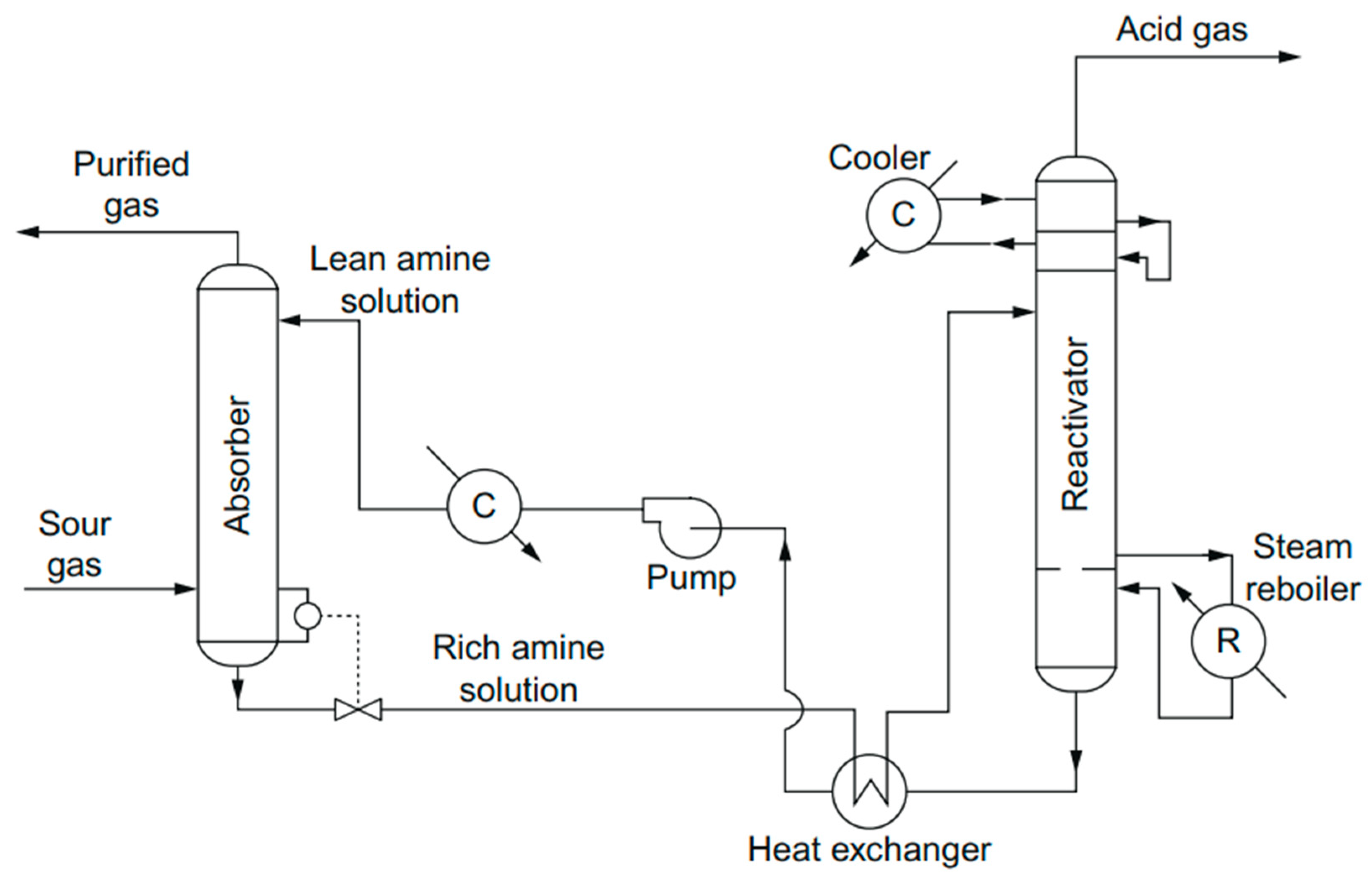
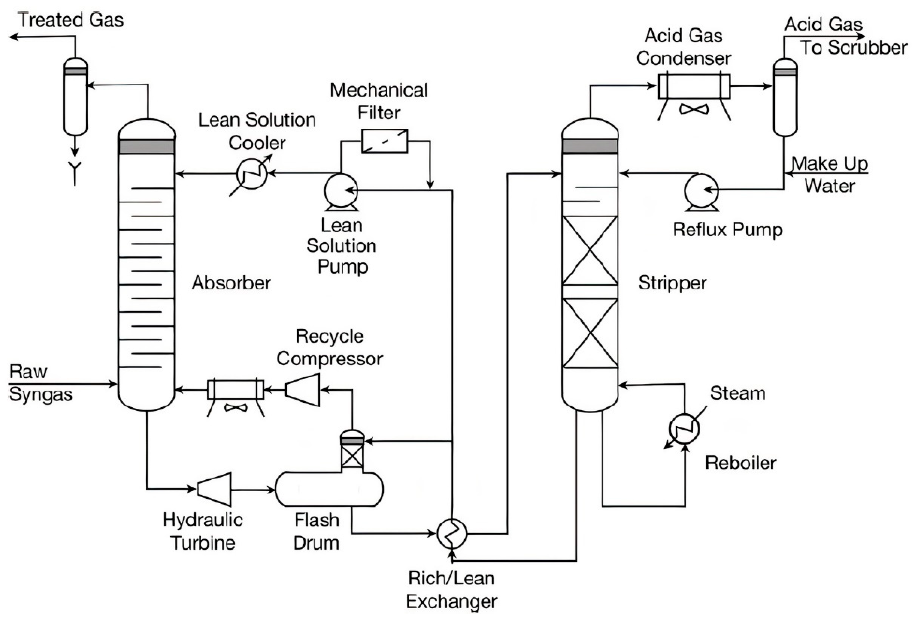
2.1. Absorption
2.2. Adsorption
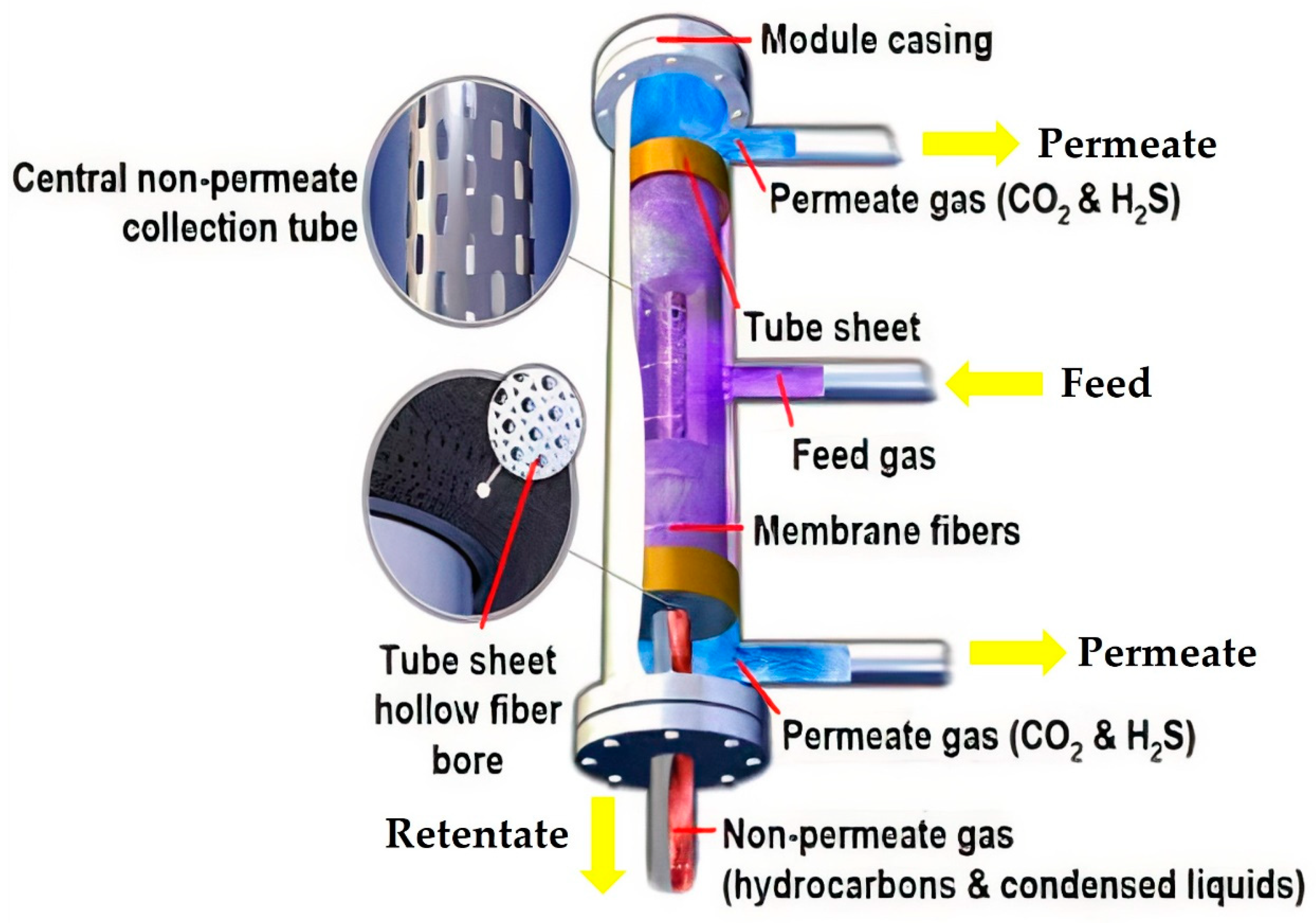
2.3. Membrane
2.4. Cryogenic Distillation
3. Advancement of Cryogenic Distillation
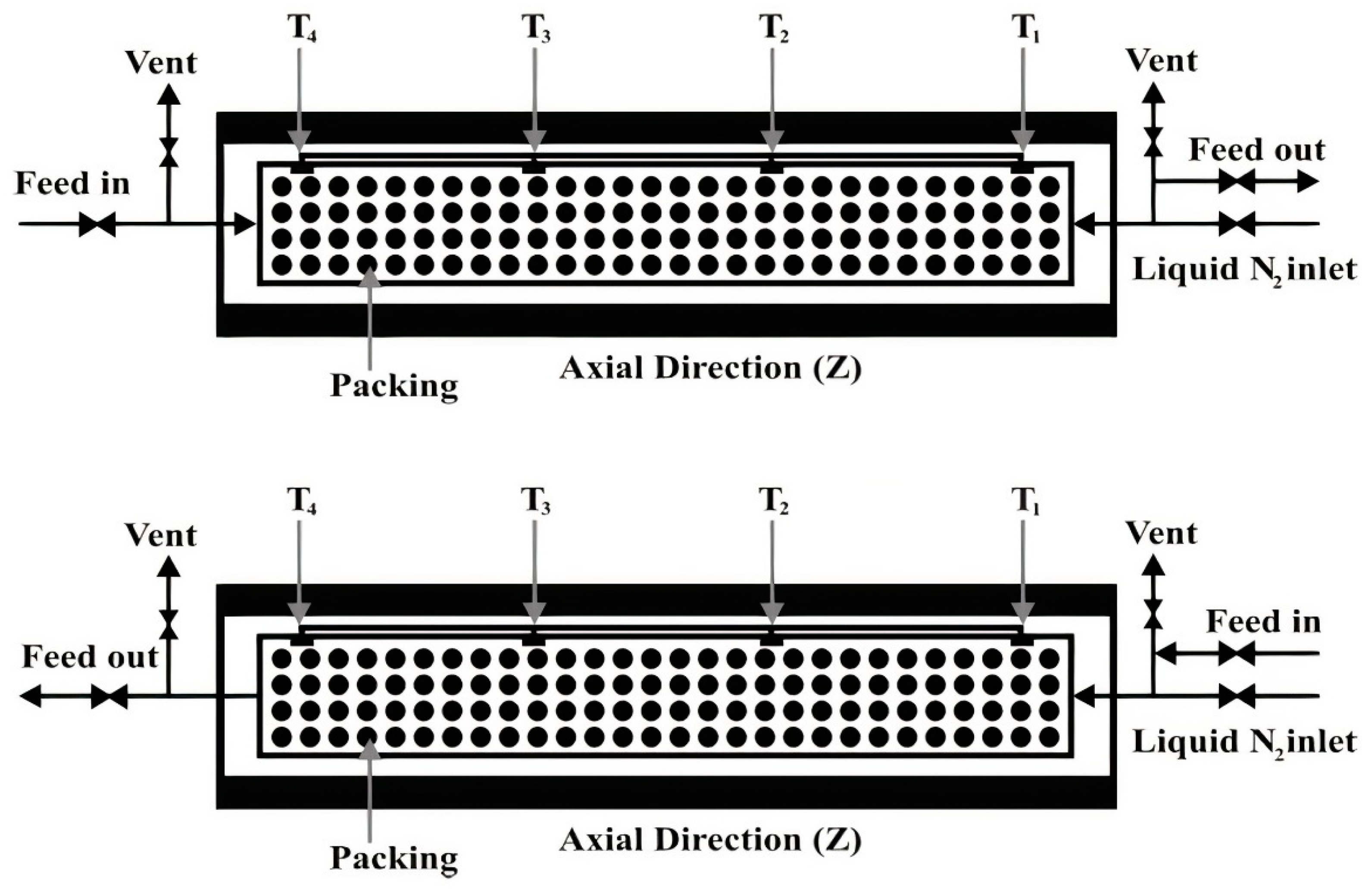
3.1. Cryogenic Packed Bed
3.2. Anti-Sublimation (AnSU)
3.3. Controlled Freeze Zone (CFZ)
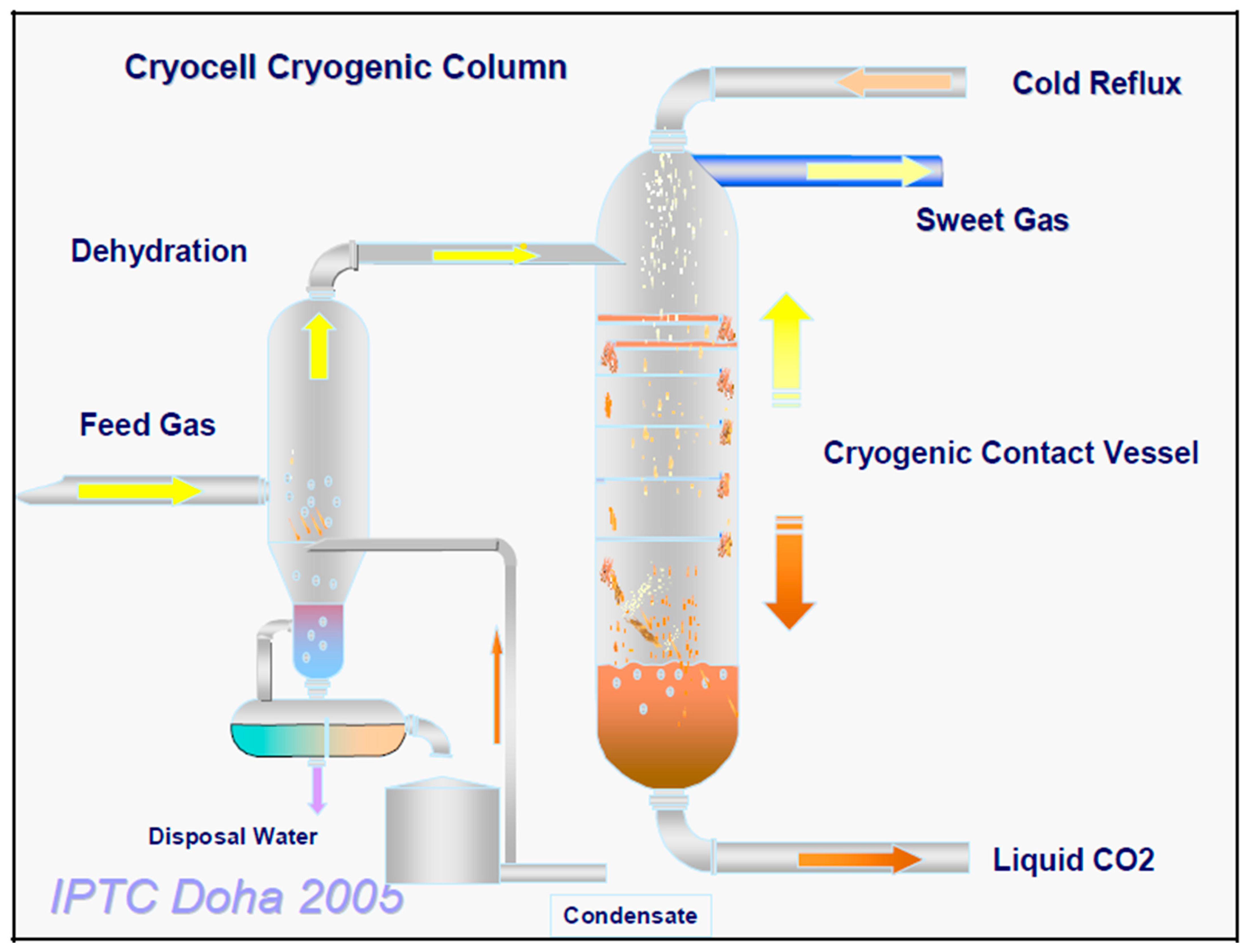
3.4. CryoCell
4. Future Outlooks and Perspectives of Cryogenic Technology
5. Conclusions
Author Contributions
Funding
Institutional Review Board Statement
Informed Consent Statement
Data Availability Statement
Acknowledgments
Conflicts of Interest
Sample Availability
References
- BP p.l.c. Statistical Review of World Energy 2021. 2021. Available online: https://www.bp.com/en/global/corporate/energy-economics/statistical-review-of-world-energy.html (accessed on 13 December 2021).
- U.S. Energy Information Administration. International Energy Outlook 2021—With Projections to 2050. 2021. Available online: https://www.eia.gov/outlooks/ieo/ (accessed on 13 December 2021).
- BP p.l.c. Energy Outlook 2020 Edition. 2020. Available online: https://www.bp.com/en/global/corporate/news-and-insights/press-releases/bp-energy-outlook-2020.html (accessed on 13 December 2021).
- International Energy Agency. Gas 2020. 2020. Available online: https://www.iea.org/reports/gas-2020 (accessed on 13 December 2021).
- Pellegrini, L.A.; Langé, S. An Innovative Technology for Natural Gas Sweetening by Means an Innovative Technology for Natural Gas Sweetening by Means of Cryogenic Distillation. In Proceedings of the GPA Europe Annual Conference, Florence, Italy, 16–18 September 2015. [Google Scholar]
- ExxonMobil. 2019 Outlook for Energy: A Perspective to 2040; 2019; pp. 1–58. Available online: https://corporate.exxonmobil.com/Energy-and-innovation/Outlook-for-Energy (accessed on 22 December 2021).
- Solutions, S.G. Natural Gas: Providing More and Cleaner Energy. Available online: https://www.shell.com/energy-and-innovation/natural-gas/providing-more-and-cleaner-energy.html (accessed on 29 October 2021).
- Mao, J.; Yang, X.; Wang, D.; Zhang, Y.; Luo, S.; Smith, G.S.; Li, Y.; Zhao, J. Optimization of effective sulfur solvents for sour gas reservoir. J. Nat. Gas Sci. Eng. 2016, 36, 463–471. [Google Scholar] [CrossRef]
- Lei, D.; Fu, D. Overview: The geological genesis in high sour gas reservoir. In Proceedings of the 2013 International Conference on Computational and Information Sciences (ICCIS ‘13), Shiyang, China, 21–23 June 2013; pp. 1220–1222. [Google Scholar]
- Georgiadis, A.; Charisiou, N.; Goula, M. Removal of Hydrogen Sulfide From Various Industrial Gases: A Review of The Most Promising Adsorbing Materials. Catalysts 2020, 10, 521. [Google Scholar] [CrossRef]
- Cherif, H. Study and Modeling of Separation Methods H2S from Methane, Selection of a Method Favoring H2S Valorization. Ph.D. Thesis, PSL Research University, Paris, France, 2016. [Google Scholar]
- Narayan, R.S.; Patton, C.J. Bulk CO2 Removal Achieved Through Membrane Separation. In Proceedings of the SPE Annual Technical Conference and Exhibition, Houston, TX, USA, 16–19 September 1984. [Google Scholar]
- Burr, B.; Lyddon, L. A Comparison of Physical Solvents for Acid Gas Removal. Water. 1998. Available online: https://www.bre.com/PDF/A-Comparison-of-Physical-Solvents-for-Acid-Gas-Removal-REVISED.pdf (accessed on 29 October 2021).
- Knuutila, H.; Svendsen, H.F.; Juliussen, O. Kinetics of carbonate based CO2 capture systems. Energy Procedia 2009, 1, 1011–1018. [Google Scholar] [CrossRef]
- Bottoms, R.R. Process for Separating Acidic Gases. U.S. Patent 1783901A, 7 October 1930. Available online: https://patents.google.com/patent/US1783901A/en (accessed on 29 October 2021).
- Vega, F.; Sanna, A.; Navarrete, B.; Maroto-Valer, M.; Cortés, V. Degradation of amine-based solvents in CO2 capture process by chemical absorption. Greenh. Gases Sci. Technol. 2014, 4, 707–733. [Google Scholar] [CrossRef]
- Vega, F.; Cano, M.; Camino, S.; Fernández, L.M.G.; Portillo, E.; Navarrete, B. Solvents for Carbon Dioxide Capture. In Capture and Oil Recovery, Karamé, I., Shaya, J., Srou, H., Eds.; IntechOpen: Rijeka, Croatia, 2018; p. 8. [Google Scholar]
- Shah, M.S.; Tsapatsis, M.; Siepmann, J.I. Hydrogen Sulfide Capture: From Absorption in Polar Liquids to Oxide, Zeolite, and Metal-Organic Framework Adsorbents and Membranes. Chem. Rev. 2017, 117, 9755–9803. [Google Scholar] [CrossRef]
- Weiland, R.H.; Hatcher, N.A.; Nava, J.L. Post-combustion CO2 Capture with Amino-Acid Salts. GPA Eur. 2010, 22, 24. [Google Scholar]
- Rogers, R.D.; Seddon, K.R. Ionic Liquids-Solvents of the Future? Science 2003, 302, 792–793. [Google Scholar] [CrossRef] [PubMed]
- Greer, A.J.; Jacquemin, J.; Hardacre, C. Industrial Applications of Ionic Liquids. Molecules 2020, 25, 5207. [Google Scholar] [CrossRef]
- Speight, J.G. Fouling During Gas Cleaning. In Fouling in Refineries; Gulf Professional Publishing: Boston, MA, USA, 2015; pp. 351–374. [Google Scholar]
- Ban, Z.H.; Keong, L.K.; Shariff, A.M. Physical absorption of CO2 capture: A review. Adv. Mater. Res. 2014, 917, 134–143. [Google Scholar] [CrossRef]
- Miller, B.G. 7-Clean Coal Technologies for Advanced Power Generation. In Clean Coal Engineering Technology; B Butterworth-Heinemann: Boston, MA, USA, 2011; pp. 251–300. [Google Scholar]
- Ghasem, N. Chapter 21—CO2 removal from natural gas. In Advances in Carbon Capture; Rahimpour, M.R., Farsi, M., Makarem, M.A., Eds.; Woodhead Publishing: Sawston, UK, 2020; pp. 479–501. [Google Scholar]
- Hu, G.; Smith, K.H.; Wu, Y.; Mumford, K.A.; Kentish, S.E.; Stevens, G.W. Carbon dioxide capture by solvent absorption using amino acids: A review. Chin. J. Chem. Eng. 2018, 26, 2229–2237. [Google Scholar] [CrossRef]
- Masoumi, S.; Rahimpour, M.R.; Mehdipour, M. Removal of carbon dioxide by aqueous amino acid salts using hollow fiber membrane contactors. J. CO2 Util. 2016, 16, 42–49. [Google Scholar] [CrossRef]
- Ciftja, A.F.; Hartono, A.; Svendsen, H.F. Selection of amine amino acids salt systems for CO2 capture. Energy Procedia 2013, 37, 1597–1604. [Google Scholar] [CrossRef]
- Erga, O.; Juliussen, O.; Lidal, H. Carbon dioxide recovery by means of aqueous amines. Energy Convers. Manag. 1995, 36, 387–392. [Google Scholar] [CrossRef]
- Wang, B.; Zhang, K.; Ren, S.; Hou, Y.; Wu, W. Efficient capture of low partial pressure H2S by tetraethyl ammonium amino acid ionic liquids with absorption-promoted solvents. RSC Adv. 2016, 6, 101462–101469. [Google Scholar] [CrossRef]
- Rouquerol, J.; Avnir, D.; Everett, D.H.; Fairbridge, C.; Haynes, M.; Pernicone, N.; Ramsay, J.D.F.; Sing, K.S.W.; Unger, K.K. Guidelines for the Characterization of Porous Solids. Stud. Surf. Sci. Catal. 1994, 87, 1–9. [Google Scholar]
- Kyzas, G.Z.; Fu, J.; Matis, K.A. The Change from Past to Future for Adsorbent Materials in Treatment of Dyeing Wastewaters. Materials 2013, 6, 5131–5158. [Google Scholar] [CrossRef]
- Robens, E. Some intriguing items in the history of adsorption. Stud. Surf. Sci. Catal. 1994, 87, 109–118. [Google Scholar]
- Gregg, S.J.; Sing, K.S.W.; Salzberg, H.W. Adsorption Surface Area and Porosity. J. Electrochem. Soc. 1967, 114, 279C. [Google Scholar] [CrossRef]
- Adam, N.K. The Adsorption of Gases and Vapours. Nature 1945, 155, 154–155. [Google Scholar] [CrossRef]
- Chappuis, P. Ueber die Wärmeerzeugung bei der Absorption der Gase durch feste Körper und Flüssigkeiten. Ann. Phys. 1883, 255, 21–38. [Google Scholar] [CrossRef]
- Sircar, S. Publications on Adsorption Science and Technology. Adsorption 2000, 6, 359–365. [Google Scholar] [CrossRef]
- Sircar, S. Applications of Gas Separation by Adsorption for the Future. Adsorpt. Sci. Technol. 2001, 19, 347–366. [Google Scholar] [CrossRef]
- Ling, J.; Ntiamoah, A.; Xiao, P.; Webley, P.A.; Zhai, Y. Effects of feed gas concentration, temperature and process parameters on vacuum swing adsorption performance for CO2 capture. Chem. Eng. J. 2015, 265, 47–57. [Google Scholar] [CrossRef]
- Tao, L.; Xiao, P.; Qader, A.; Webley, P.A. CO2 capture from high concentration CO2 natural gas by pressure swing adsorption at the CO2CRC Otway site, Australia. Int. J. Greenh. Gas Control 2019, 83, 1–10. [Google Scholar] [CrossRef]
- Grande, C.A. Advances in Pressure Swing Adsorption for Gas Separation. ISRN Chem. Eng. 2012, 2012, 982934. [Google Scholar] [CrossRef]
- Ho, M.T.; Allinson, G.W.; Wiley, D.E. Reducing the Cost of CO2 Capture from Flue Gases Using Pressure Swing Adsorption. Ind. Eng. Chem. Res. 2008, 47, 4883–4890. [Google Scholar] [CrossRef]
- Fouladi, N.; Makarem, M.A.; Sedghamiz, M.A.; Rahimpour, H.R. Chapter 11—CO2 adsorption by swing technologies and challenges on industrialization. In Advances in Carbon Capture; Rahimpour, M.R., Farsi, M., Makarem, M.A., Eds.; Woodhead Publishing: Sawston, UK, 2020; pp. 241–267. [Google Scholar] [CrossRef]
- Bonnissel, M.P.; Luo, L.; Tondeur, D. Rapid Thermal Swing Adsorption. Ind. Eng. Chem. Res. 2001, 40, 2322–2334. [Google Scholar] [CrossRef]
- Mérel, J.; Clausse, M.; Meunier, F. Carbon dioxide capture by indirect thermal swing adsorption using 13X zeolite. Environ. Prog. 2006, 25, 327–333. [Google Scholar] [CrossRef]
- Chaffee, A.L.; Knowles, G.; Liang, Z.; Zhang, J.; Xiao, P.; Webley, P. CO2 capture by adsorption: Materials and process development. Int. J. Greenh. Gas Control 2007, 1, 11–18. [Google Scholar] [CrossRef]
- Grande, C.A.; Rodrigues, A.E. Electric Swing Adsorption for CO2 removal from flue gases. Int. J. Greenh. Gas Control 2008, 2, 194–202. [Google Scholar] [CrossRef]
- Le Cloirec, P. Adsorption onto Activated Carbon Fiber Cloth and Electrothermal Desorption of Volatile Organic Compound (VOCs): A Specific Review. Chin. J. Chem. Eng. 2012, 20, 461–468. [Google Scholar] [CrossRef]
- Berger, A.H.; Bhown, A.S. Comparing physisorption and chemisorption solid sorbents for use separating CO2 from flue gas using temperature swing adsorption. Energy Procedia 2011, 4, 562–567. [Google Scholar] [CrossRef]
- Xing, W.; Liu, C.; Zhou, Z.; Zhou, J.; Wang, G.; Zhuo, S.; Xue, Q.; Song, L.; Yan, Z. Oxygen-containing functional group-facilitated CO2 capture by carbide-derived carbons. Nanoscale Res. Lett. 2014, 9, 189. [Google Scholar] [CrossRef]
- Kulkarni, S.; Kaware, J. Regeneration and recovery in adsorption-a review. Int. J. Innov. Sci. Eng. Technol. 2014, 1, 61–64. [Google Scholar]
- Costa, C.; Cornacchia, M.; Pagliero, M.; Fabiano, B.; Vocciante, M.; Reverberi, A. Hydrogen Sulfide Adsorption by Iron Oxides and Their Polymer Composites: A Case-Study Application to Biogas Purification. Materials 2020, 13, 4725. [Google Scholar] [CrossRef]
- Hussain, M.; Abbas, N.; Fino, D.; Russo, N. Novel mesoporous silica supported ZnO adsorbents for the desulphurization of biogas at low temperatures. Chem. Eng. J. 2012, 188, 222–232. [Google Scholar] [CrossRef]
- Montes, D.; Tocuyo, E.; Gonzalez, E.; Rodríguez, D.; Solano, R.; Atencio, R.; Ramos, M.A.; Moronta, A. Reactive H2S chemisorption on mesoporous silica molecular sieve-supported CuO or ZnO. Microporous Mesoporous Mater. 2013, 168, 111–120. [Google Scholar] [CrossRef]
- Lincke, M.; Petasch, U.; Gaitzsch, U.; Tillmann, A.; Tietze, M.; Niebling, F. Chemoadsorption for separation of hydrogen sulfide from biogas with iron hydroxide and sulfur recovery. Chem. Eng. Technol. 2020, 43, 1564–1570. [Google Scholar] [CrossRef]
- De Oliveira, L.H.; Meneguin, J.G.; Pereira, M.V.; da Silva, E.A.; Grava, W.M.; do Nascimento, J.F.; Arroyo, P.A. H2S adsorption on NaY zeolite. Microporous Mesoporous Mater. 2019, 284, 247–257. [Google Scholar] [CrossRef]
- Thanakunpaisit, N.; Jantarachat, N.; Onthong, U. Removal of Hydrogen Sulfide from Biogas using Laterite Materials as an Adsorbent. Energy Procedia 2017, 138, 1134–1139. [Google Scholar] [CrossRef]
- Abdullah, A.H.; Mat, R.; Aziz, A.S.A.; Roslan, F. Use of kaolin as adsorbent for removal of hydrogen sulphide from biogas. Chem. Eng. Trans. 2017, 56, 763–768. [Google Scholar]
- Lin, Y.-H.; Chen, Y.-C.; Chu, H. The mechanism of coal gas desulfurization by iron oxide sorbents. Chemosphere 2015, 121, 62–67. [Google Scholar] [CrossRef] [PubMed]
- Chiarioni, A.; Reverberi, A.; Fabiano, B.; Dovi’, V. An improved model of an ASR pyrolysis reactor for energy recovery. Energy 2006, 31, 2460–2468. [Google Scholar] [CrossRef]
- Elyassi, B.; Al Wahedi, Y.; Rajabbeigi, N.; Kumar, P.; Jeong, J.S.; Zhang, X.; Kumar, P.; Balasubramanian, V.V.; Katsiotis, M.S.; Mkhoyan, K.A.; et al. A high-performance adsorbent for hydrogen sulfide removal. Microporous Mesoporous Mater. 2014, 190, 152–155. [Google Scholar] [CrossRef]
- Belmabkhout, Y.; Heymans, N.; De Weireld, G.; Sayari, A. Simultaneous Adsorption of H2S and CO2 on Triamine-Grafted Pore-Expanded Mesoporous MCM-41 Silica. Energy Fuels 2011, 25, 1310–1315. [Google Scholar] [CrossRef]
- Huang, H.Y.; Yang, R.T.; Chinn, D.; Munson, C.L. Amine-Grafted MCM-48 and Silica Xerogel as Superior Sorbents for Acidic Gas Removal from Natural Gas. Ind. Eng. Chem. Res. 2003, 42, 2427–2433. [Google Scholar] [CrossRef]
- Ma, X.; Wang, X.; Song, C. “Molecular Basket” Sorbents for Separation of CO2 and H2S from Various Gas Streams. J. Am. Chem. Soc. 2009, 131, 5777–5783. [Google Scholar] [CrossRef]
- Bülow, M.; Lutz, W.; Suckow, M. The mutual transformation of hydrogen sulphide and carbonyl sulphide and its role for gas desulphurization processes with zeolitic molecular sieve sorbents. Stud. Surf. Sci. Catal. 1999, 120, 301–345. [Google Scholar]
- Gordano, A.; Buonomenna, M.G.; Idris, A.; Ahmed, I.; Noor, N.M.; Liu, J.; Xu, T.; Shao, G.; Jana, S.; Purkait, M.K.; et al. Membrane Technologies and Applications; Purkait, M.K., Mohanty, K., Eds.; CRC Press: Boca Raton, FL, USA, 2012. [Google Scholar]
- Liu, C.; Greer, D.W.; O’Leary, B.W. Advanced Materials and Membranes for Gas Separations: The UOP Approach. ACS Symp. Ser. 2016, 1224, 119–135. [Google Scholar]
- Bernardo, P.; Drioli, E.; Golemme, G. Membrane Gas Separation: A Review/State of the Art. Ind. Eng. Chem. Res. 2009, 48, 4638–4663. [Google Scholar] [CrossRef]
- Mordor Intelligence. Gas Separation Membrane Market-Growth, Trends, COVID-19 Impact, and Forecasts (2021–2026). 2020. Available online: https://www.mordorintelligence.com/industry-reports/gas-separation-membrane-market (accessed on 25 October 2021).
- Pabby, A.K.; Rizvi, S.S.H.; Requena, A.M.S. Handbook of Membrane Separations-Chemical, Pharmaceutical, Food, and Biotechnological Applications, 2nd ed.; CRC Press: Boca Raton, FL, USA, 2015. [Google Scholar]
- He, X.; Hägg, M.-B. Membranes for Environmentally Friendly Energy Processes. Membranes 2012, 2, 706–726. [Google Scholar] [CrossRef]
- Jariwala, A. High H2S Gas Field Monetization: A Novel Approach. In Proceedings of the Offshore Technology Conference, Houston, TX, USA, 6–9 May 2019. [Google Scholar]
- Lin, H.; White, L.S.; Lokhandwala, K.; Baker, R.W. Natural Gas Purification. In Encyclopedia of Membrane Science and Technology; John Wiley & Sons, Inc.: Hoboken, NJ, USA, 2013; pp. 1–25. [Google Scholar] [CrossRef]
- Sanghani, P.; Kumar, H.; Ghorbani, N.; Morisato, A.; Mahley, G. Sour Gas Has A Sweeter Future-Bulk H2S Removal Using Polymeric Cellulose Triacetate Based Membranes. In Proceedings of the Abu Dhabi International Petroleum Exhibition & Conference 2020, Abu Dhabi, United Arab Emirates, 11 November 2020. [Google Scholar]
- Callison, A.; Davidson, G. Offshore processing plant uses membranes for CO2 removal. Oil Gas J. 2007, 105, 56–65. [Google Scholar]
- Jusoh, N.; Lau, K.K.; Shariff, A.M.; Yeong, Y.F. Capture of bulk CO2 from methane with the presence of heavy hydrocarbon using membrane process. Int. J. Greenh. Gas Control 2014, 22, 213–222. [Google Scholar] [CrossRef]
- Jusoh, N.; Lau, K.K.; Shariff, A.M. Removal of Bulk CO2 from Methane with the Presenceof Heavy Hydrocarbon using Polyimide Membrane. J. Teknol. 2014, 69, 41–46. [Google Scholar] [CrossRef][Green Version]
- Nafisi, V.; Hägg, M.B. Gas separation properties of ZIF-8/6FDA-durene diamine mixed matrix membrane. Sep. Purif. Technol. 2014, 128, 31–38. [Google Scholar] [CrossRef]
- Zhu, W.; Hrabanek, P.; Gora, L.; Kapteijn, F.; Moulijn, J.A. Role of Adsorption in the Permeation of CH4 and CO2 through a Silicalite-1 Membrane. Ind. Eng. Chem. Res. 2006, 45, 767–776. [Google Scholar] [CrossRef]
- Li, S.; Martinek, J.G.; Falconer, J.L.; Noble, R.D.; Gardner, T.Q. High-Pressure CO2/CH4 Separation Using SAPO-34 Membranes. Ind. Eng. Chem. Res. 2005, 44, 3220–3228. [Google Scholar] [CrossRef]
- Li, S.; Falconer, J.L.; Noble, R.D. Improved SAPO-34 membranes for CO2/CH4 separations. Adv. Mater. 2006, 18, 2601–2603. [Google Scholar] [CrossRef]
- Himeno, S.; Tomita, T.; Suzuki, K.; Nakayama, K.; Yajima, K.; Yoshida, S. Synthesis and permeation properties of a DDR-type zeolite membrane for separation of CO2/CH4 gaseous mixtures. Ind. Eng. Chem. Res. 2007, 46, 6989–6997. [Google Scholar] [CrossRef]
- Mubashir, M.; Fong, Y.Y.; Keong, L.K.; Sharrif, M.A.B. Synthesis and performance of deca-dodecasil 3 rhombohedral (ddr)-type zeolite membrane in CO2 separation—A review. ASEAN J. Chem. Eng. 2015, 14, 48–57. [Google Scholar] [CrossRef]
- Poshusta, J.C.; Tuan, V.A.; Pape, E.A.; Noble, R.D.; Falconer, J.L. Separation of light gas mixtures using SAPO-34 membranes. AIChE J. 2000, 46, 779–789. [Google Scholar] [CrossRef]
- Cui, Y.; Kita, H.; Okamoto, K.-I. Preparation and gas separation performance of zeolite T membrane. J. Mater. Chem. 2004, 14, 924–932. [Google Scholar] [CrossRef]
- Lu, H.T. The Impact of Impurities on the Performance of Cellulose Triacetate Membranes for CO2 Separation. Ph.D. Thesis, Chemical Engineering Department, School of Chemical and Biomedical Engineering, The University of Melbourne, Melbourne, Australia, 2018. [Google Scholar]
- Chatterjee, G.; Houde, A.; Stern, S. Poly(ether urethane) and poly(ether urethane urea) membranes with high H2S/CH4 selectivity. J. Membr. Sci. 1997, 135, 99–106. [Google Scholar] [CrossRef]
- Sadeghi, M.; Talakesh, M.M.; Shamsabadi, A.A.; Soroush, M. Novel Application of a Polyurethane Membrane for Efficient Separation of Hydrogen Sulfide from Binary and Ternary Gas Mixtures. ChemistrySelect 2018, 3, 3302–3308. [Google Scholar] [CrossRef]
- Harrigan, D.J.; Yang, J.; Sundell, B.J.; Lawrence III, J.A.; O’Brien, J.T.; Ostraat, M.L. Sour gas transport in poly (ether-b-amide) membranes for natural gas separations. J. Membr. Sci. 2020, 595, 117497. [Google Scholar] [CrossRef]
- Achoundong, C.S.K.; Bhuwania, N.; Burgess, S.K.; Karvan, O.; Johnson, J.R.; Koros, W.J. Silane Modification of Cellulose Acetate Dense Films as Materials for Acid Gas Removal. Macromolecules 2013, 46, 5584–5594. [Google Scholar] [CrossRef]
- Schlumberger. Petronas Gas Plant Reduces Costs with Dual-Core Acid Gas Removal Membranes. 2018. Available online: https://www.slb.com/resource-library/case-study/osf/cynara-pn-1-petronas-malaysia-cs (accessed on 25 October 2021).
- Schlumberger. CYNARA-Acid Gas Removal Membrane Systems. 2016. Available online: https://www.slb.com/well-production/processing-and-separation/gas-treatment/cynara-acid-gas-removal-membrane-systems (accessed on 25 October 2021).
- Bhide, B.; Voskericyan, A.; Stern, S. Hybrid processes for the removal of acid gases from natural gas. J. Membr. Sci. 1998, 140, 27–49. [Google Scholar] [CrossRef]
- Rezakazemi, M.; Heydari, I.; Zhang, Z. Hybrid systems: Combining membrane and absorption technologies leads to more efficient acid gases (CO2 and H2S) removal from natural gas. J. CO2 Util. 2017, 18, 362–369. [Google Scholar] [CrossRef]
- Liebmann, A.J. History of distillation. J. Chem. Educ. 1956, 33, 166. [Google Scholar] [CrossRef]
- Taylor, F.S. The evolution of the still. Ann. Sci. 1945, 5, 185–202. [Google Scholar] [CrossRef]
- Chambers, J.M. Alcohol Distillation Process. U.S. Patent 2647078, 17 December 1949. Available online: https://patents.google.com/patent/US2647078A/en (accessed on 27 October 2021).
- Kaymak, D.B.; Luyben, W.L.; Smith IV, O.J. Effect of relative volatility on the quantitative comparison of reactive distillation and conventional multi-unit systems. Ind. Eng. Chem. Res. 2004, 43, 3151–3162. [Google Scholar] [CrossRef]
- Department of Chemical and Environmental Process Engineering. Packed Distillation Columns; Budapest University of Technology and Economics: Budapest, Hungary, 2016; pp. 1–7. [Google Scholar]
- Blahušiak, M.; Kiss, A.; Kersten, S.; Schuur, B. Quick assessment of binary distillation efficiency using a heat engine perspective. Energy 2016, 116, 20–31. [Google Scholar] [CrossRef]
- Pilling, M.; Holden, B.S. Choosing trays and packings for distillation. Am. Inst. Chem. Eng. CEP 2009, 105, 44–50. [Google Scholar]
- Spiegel, L.; Duss, M. Structured Packings; Elsevier Inc.: Amsterdam, The Netherlands, 2014. [Google Scholar]
- Patil, K.; Choudhary, P.; Bhatia, T. Distillation Operations: Methods, Operational and Design Issues. In Proceedings of the National Conference on Advances in Heat & Mass Transfer, FAMT, Ratnagiri, India, 30–31 October 2009; pp. 1–9. [Google Scholar]
- Agarwal, S.; Taylor, R. Distillation Column Design Calculations Using a Nonequilibrium Model. Ind. Eng. Chem. Res. 1994, 33, 2631–2636. [Google Scholar] [CrossRef]
- Kolmetz, K.; Ng, W.K.; Lee, S.H.; Lim, T.Y.; Summers, D.R.; Soyza, C.A. Optimize distillation column design for improved reliability in operation and maintenance. Asia-Pac. J. Chem. Eng. 2007, 2, 294–307. [Google Scholar] [CrossRef]
- Kolmetz, K.; Jaya, A. Distillation Column Reboiler Selection, Sizing, and Troubleshooting. In Kolmetz Handbook of Process Equipment Design; KLM Technology Group: Johor Bahru, Malaysia, 2013; Available online: https://www.klmtechgroup.com/PDF/EDG-SYS/ENGINEERING-DESIGN-GUIDELINES-reboiler-Rev1.3web.pdf (accessed on 27 October 2021).
- Taqvi, S.A.; Tufa, L.D.; Muhadizir, S. Optimization and Dynamics of Distillation Column Using Aspen Plus®. Procedia Eng. 2016, 148, 978–984. [Google Scholar] [CrossRef]
- Font-Palma, C.; Cann, D.; Udemu, C. Review of Cryogenic Carbon Capture Innovations and Their Potential Applications. J. Carbon Res. 2021, 7, 58. [Google Scholar] [CrossRef]
- Fitzmorris, R.E.; Mah, R.S.H. Improving distillation column design using thermodynamic availability analysis. AIChE J. 1980, 26, 265–273. [Google Scholar] [CrossRef]
- Song, C.; Liu, Q.; Deng, S.; Li, H.; Kitamura, Y. Cryogenic-based CO2 capture technologies: State-of-the-art developments and current challenges. Renew. Sustain. Energy Rev. 2019, 101, 265–278. [Google Scholar] [CrossRef]
- Ali, A.; Maqsood, K.; Syahera, N.; Shariff, A.B.; Ganguly, S. Energy minimization in cryogenic packed beds during purification of natural gas with high CO2 content. Chem. Eng. Technol. 2014, 37, 1675–1685. [Google Scholar] [CrossRef]
- Tuinier, M.; Annaland, M.V.S.; Kramer, G.; Kuipers, H. Cryogenic CO2 capture using dynamically operated packed beds. Chem. Eng. Sci. 2010, 65, 114–119. [Google Scholar] [CrossRef]
- Tuinier, M.; Annaland, M.V.S.; Kuipers, H. A novel process for cryogenic CO2 capture using dynamically operated packed beds—An experimental and numerical study. Int. J. Greenh. Gas Control 2011, 5, 694–701. [Google Scholar] [CrossRef]
- Tuinier, M.J.; Annaland, M.V.S. Biogas Purification Using Cryogenic Packed-Bed Technology. Ind. Eng. Chem. Res. 2012, 51, 5552–5558. [Google Scholar] [CrossRef]
- Demko, J.; Fesmire, J.E.; Johnson, W.L.; Swanger, A.M. Cryogenic Insulation Standard Data And Methodologies. AIP Conf. Proc. 2014, 1573, 463–470. [Google Scholar]
- Baxter, L.; Baxter, A.; Burt, S. Cryogenic CO2 capture as a cost-effective CO2 capture process. In Proceedings of the 26th Annual International Pittsburgh Coal Conference 2009, PCC 2009, Pittsburgh, PA, USA, 20–23 September 2009. [Google Scholar]
- Fu, Q.; Kansha, Y.; Song, C.; Liu, Y.; Ishizuka, M.; Tsutsumi, A. An Advanced Cryogenic Air Separation Process Based on Self-heat Recuperation for CO2 Separation. Energy Procedia 2014, 61, 1673–1676. [Google Scholar] [CrossRef]
- Berstad, D.; Anantharaman, R.; Nekså, P. Low-temperature CO2 capture technologies—Applications and potential. Int. J. Refrig. 2013, 36, 1403–1416. [Google Scholar] [CrossRef]
- Pan, X.; Clodic, D.; Toubassy, J. CO2 capture by antisublimation process and its technical economic analysis. Greenh. Gases Sci. Technol. 2013, 3, 8–20. [Google Scholar] [CrossRef]
- Maqsood, K.; Mullick, A.; Ali, A.; Kargupta, K.; Ganguly, S. Cryogenic carbon dioxide separation from natural gas: A review based on conventional and novel emerging technologies. Rev. Chem. Eng. 2014, 30, 453–477. [Google Scholar] [CrossRef]
- Clodic, D.; Younes, M. A new method for CO2 capture: Frosting CO2 at atmospheric pressure. In Proceedings of the 6th International Conference on Greenhouse Gas Control Technologies, Kyoto, Japan, 1–4 October 2002; pp. 155–160. [Google Scholar]
- Clodic, D.; Younes, M.; Bill, A. Test results of CO2 capture by anti-sublimation Capture efficiency and energy consumption for Boiler plants. In Greenhouse Gas Control Technologies 7; Elsevier Science Ltd.: Amsterdam, The Netherlands, 2005; pp. 1175–1780. [Google Scholar]
- Clodic, D.; Hitti, R.; Younes, M.; Bill, A.; Casier, F. CO2 capture by anti-sublimation Thermo-economic process evaluation. In Proceedings of the Fourth Annual Conference on Carbon Capture and Sequestration, Alexandria, VA, USA, 2–5 May 2005. [Google Scholar]
- Schach, M.-O.; Oyarzún, B.; Schramm, H.; Schneider, R.; Repke, J.-U. Feasibility study of CO2 capture by anti-sublimation. Energy Procedia 2011, 4, 1403–1410. [Google Scholar] [CrossRef]
- Abdulsalam, J.; Mulopo, J.; Amosa, M.; Bada, S.; Falcon, R.; Oboirien, B.O. Towards a cleaner natural gas production: Recent developments on purification technologies. Sep. Sci. Technol. 2018, 54, 2461–2497. [Google Scholar] [CrossRef]
- Haut, R.C.; Denton, R.D.; Thomas, E.R. Development and application of the controlled-freeze-zone process. SPE Prod. Eng. 1989, 4, 265–271. [Google Scholar] [CrossRef]
- Nichols, J.L.V.; Friedman, B.M.; Nold, A.L.; McCutcheon, S.; Goethe, A. Processing technologies for CO2 rich gas. In Proceedings of the 88th Annual Convention of the Gas Processors Association, San Antonio, TX, USA, 8–11 March 2009. [Google Scholar]
- Rufford, T.E.; Smart, S.; Watson, G.C.; Graham, B.F.; Boxall, J.; Da Costa, J.D.; May, E.F. The removal of CO2 and N2 from natural gas: A review of conventional and emerging process technologies. J. Pet. Sci. Eng. 2012, 94, 123–154. [Google Scholar] [CrossRef]
- Valencia, J.; Northrop, P.; Mart, C. Controlled Freeze ZoneTM Technology for Enabling Processing of High CO2 and H2S Gas Reserves. In Proceedings of the IPTC 2008: International Petroleum Technology Conference, Kuala Lumpur, Malaysia, 3–5 December 2008. [Google Scholar]
- Northrop, P.S.; Valencia, J.A. The CFZ™ process: A cryogenic method for handling high-CO2 and H2S gas reserves and facilitating geosequestration of CO2 and acid gases. Energy Procedia 2009, 1, 171–177. [Google Scholar] [CrossRef]
- Valencia, J.A.; Kelman, S.D. The Controlled Freeze ZoneTM Technology for the Development of Sour Gas Resources. In Proceedings of the International Petroleum Technology Conference 2013, Beijing, China, 26–28 March 2013. [Google Scholar]
- Valencia, J.A.; Denton, R.D.; Northrop, P.S.; Mart, C.J.; Smith, R.K. Controlled freeze zone technology for the commercialization of Australian high CO2 natural gas. In Proceedings of the Society of Petroleum Engineers-SPE Asia Pacific Oil and Gas Conference Exhibition APOGCE 2014-Changing the Game: Opportunities, Challenges and Solutions, Adelaide, Australia, 14–16 October 2014; Volume 2, pp. 951–961. [Google Scholar]
- Mart, C.J.C. Controlled Freeze ZoneTM Technology–An Integrated Solution for Processing Sour Natural Gas. Glob. Clim. Energy Proj. Res. Symp. 2009. Available online: https://gcep.stanford.edu/events/symposium2009/presentations.html (accessed on 27 October 2021).
- Northrop, S.; Seagraves, J.; Ramkumar, S.; Cullinane, T. Exxonmobil’s experience with sour gas treating and acid gas handling. In Proceedings of the Abu Dhabi International Petroleum Exhibition & Conference ADIP 2019, Abu Dhabi, United Arab Emirates, 11–14 November 2019. [Google Scholar]
- Hart, A.; Gnanendran, N. Cryogenic CO2 capture in natural gas. Energy Procedia 2009, 1, 697–706. [Google Scholar] [CrossRef]
- Amin, R.; Jackson, A.; Kennaird, T. The Cryocell: An Advanced Gas-Sweetening Technology. In Proceedings of the International Petroleum Technology Conference This, Doha, Qatar, 21–23 November 2005; pp. 1–5. [Google Scholar]
- Park, J.; Yoon, S.; Oh, S.Y.; Kim, Y.; Kim, J.K. Improving energy efficiency for a low-temperature CO2 separation process in natural gas processing. Energy 2021, 214, 118844. [Google Scholar] [CrossRef]
- Babar, M.; Bustam, M.A.; Ali, A.; Maulud, A.S.; Shafiq, U.; Mukhtar, A.; Shah, S.N.; Maqsood, K.; Mellon, N.; Shariff, A.M. Thermodynamic data for cryogenic carbon dioxide capture from natural gas: A review. Cryogenics 2019, 102, 85–104. [Google Scholar] [CrossRef]
- Babar, M.; Bustam, M.A.; Ali, A.; Maulud, A.S. Identification and Quantification of CO2 Solidification in Cryogenic CO2 Capture from Natural Gas. Int. J. Automot. Mech. Eng. 2018, 15, 5367–5376. [Google Scholar] [CrossRef]
- Liu, B.; Yang, X.; Chiang, P.; Wang, T. Energy Consumption Analysis of Cryogenic-Membrane Hybrid Process for CO2 Capture from CO2 EOR Extraction Gas. In Aerosol and Air Quality Research; Taiwan Association for Aerosol Research: Taoyuan City, Taiwan, 2020; Volume 20, pp. 820–832. [Google Scholar]


| Category | Insights |
|---|---|
| Conventional CO2 and H2S separation technologies | Gas separation mechanisms of the conventional technologies—absorption, adsorption and membranes and cryogenic separation. Research and development of technologies for sour natural gas treatment Challenges or limitations of conventional separation technologies |
| Advanced cryogenic distillation process | Modifications or advancements in the conventional cryogenic process—cryogenic packed bed, anti-sublimation, controlled freeze zone (CFZ) and CryoCell The extent of the capability of the processes to handle bulk CO2 and H2S in sour natural gas State-of-the-art and perspective of the advanced cryogenic process for natural gas upgrading application |
| Technology Used | Adsorption | AnSU |
|---|---|---|
| Power plant efficiency loss | 12.5% | 10.7% |
| Total electrical power required | 209 MW | 178 MW |
| Specific electric required | 0.391 kWh/kg CO2 | 0.286 kWh/kg CO2 |
Publisher’s Note: MDPI stays neutral with regard to jurisdictional claims in published maps and institutional affiliations. |
© 2022 by the authors. Licensee MDPI, Basel, Switzerland. This article is an open access article distributed under the terms and conditions of the Creative Commons Attribution (CC BY) license (https://creativecommons.org/licenses/by/4.0/).
Share and Cite
Tengku Hassan, T.N.A.; Shariff, A.M.; Mohd Pauzi, M.M.; Khidzir, M.S.; Surmi, A. Insights on Cryogenic Distillation Technology for Simultaneous CO2 and H2S Removal for Sour Gas Fields. Molecules 2022, 27, 1424. https://doi.org/10.3390/molecules27041424
Tengku Hassan TNA, Shariff AM, Mohd Pauzi MM, Khidzir MS, Surmi A. Insights on Cryogenic Distillation Technology for Simultaneous CO2 and H2S Removal for Sour Gas Fields. Molecules. 2022; 27(4):1424. https://doi.org/10.3390/molecules27041424
Chicago/Turabian StyleTengku Hassan, Tengku Nur Adibah, Azmi Mohd Shariff, Mohd Mu’izzuddin Mohd Pauzi, Mai Syadiah Khidzir, and Amiza Surmi. 2022. "Insights on Cryogenic Distillation Technology for Simultaneous CO2 and H2S Removal for Sour Gas Fields" Molecules 27, no. 4: 1424. https://doi.org/10.3390/molecules27041424
APA StyleTengku Hassan, T. N. A., Shariff, A. M., Mohd Pauzi, M. M., Khidzir, M. S., & Surmi, A. (2022). Insights on Cryogenic Distillation Technology for Simultaneous CO2 and H2S Removal for Sour Gas Fields. Molecules, 27(4), 1424. https://doi.org/10.3390/molecules27041424