Abstract
The hanger often needs to be replaced many times during the operation period of hanger arch bridges. To ensure the safety of the hanger replacement in the construction process of pocket hanging, the structural response in the whole construction process needs to be precisely controlled. In this paper, aiming at half-through arches with a suspended deck by cable hangers, the precise displacement controlling method for hanger replacement of an arch bridge based on the pocket hanging method has been proposed. Firstly, the equivalent model of an arch bridge in the hanger replacement process is established, and the boundary conditions of the equivalent model are calculated precisely. Secondly, in the hanger replacement process, including old hanger demolition and new hanger installation, the precise displacement expressions of the suspended deck are derived on the basis of the equivalent model. Finally, the correctness and feasibility of the proposed precise displacement controlling method are verified by the hanger replacement engineering of an arch bridge. Through this research on the hanger replacement of an arch bridge, the equivalent model adopted in this paper has been proven accurate, and only partial boundary conditions need to be considered in practical engineering applications to get accurate results. Meanwhile, the calculation results are accurate enough through the practical engineering verification, and the precise displacement controlling method is feasible in the hanger replacement process of an arch bridge based on the pocket hanging method. It is also found that satisfactory results can be achieved using hanger demolition and installation by equal step length.
1. Introduction
Arch bridges have been widely used for their extreme competitiveness among various types of bridges due to their advantages, such as a large spanning ability, a beautiful shape, and reasonable structural force [1,2,3,4]. According to an incomplete survey, over 600 arch bridges have been built in China, in which the load must be transmitted through the hanger whether it is half-through or through the arch bridge. Among the hanger components of an arch bridge, hangers transmit wind or live loads on the deck to the main rib, which are then transmitted to the earth. Hanger safety is thus directly related to the safety of the entire bridge [5,6,7,8].
A hanger is usually designed as a replaceable part, and their design life is much shorter than the design life of the bridge structure. Hangers located in a complex environment are not only subjected to constant load (i.e., structural weight) as well as alternating loads (i.e., temperature, vehicles, wind, etc.), but also corrosive conditions such as humidity, high chloride ions, and changing temperature [9,10]. These complex factors can lead to the service life of the hangers (8~16 years) being much shorter than their design life (i.e., 20 years) [11]. Thus, hanger replacement is a very common measure in the repair process of arch bridges [12,13,14,15]. Even beam bridge structures such as reinforced concrete bridges or steel bridges will fail or collapse due to material degradation, and some necessary maintenance and reinforcement measures need to be taken during their service period [16,17,18,19]. In China, more than 30 out of over 600 arch bridges have undergone the hanger replacement process [12,20]. With the extension of service life, there will be more and more arch bridges that need hanger replacement. The commonly used hanger replacement methods include the temporary bracket method, temporary hanger method, and pocket hanging method, of which the pocket hanging method has been widely used due to its advantages such as a clear conversion system, reasonable structural force, and no need to close traffic [21].
Suspenders are critical force transmission components in suspension and arch bridges, which connect the girder to the main cable/arch. In recent years, a lot of research has been carried out on issues related to cable replacement of cable-stayed bridges and suspension bridges. Hossain et al. [22] summed up a cable replacement process for thae suspension bridge. Ferreira et al. [23,24] and Simoes and Negrao et al. [25] presented an optimization algorithm to solve the structural-control design problem of cable-stayed bridges and carried out the static, dynamic, and erection stage analysis simultaneously. Hangers must be replaced promptly when severe damage occurs. Sun et al. [12] proposed a replacement method using temporary hangers and performed field implementation of hanger replacement for a suspension. In order to ensure the safety and reliability of the cable replacement, reasonable mechanical analysis and construction control should be carried out on the cable replacement process. Yao et al. [26] adopted the finite element method on Tianjin Yonghe bridge to simulate each stage of the cable replacement process; the dates of tension, the alignment of the main beam, and the change of stress before and after the cable replacement were compared and analyzed. Sun et al. [27] used Kalman’s filtering method in the construction control for cable replacement combined with the cable replacement project of Jiao-Ping Du cable-stayed bridge. The results showed that the cable tension of the cable-stayed bridge was 2926 kN less than the design cable tension after changing the cable of this bridge. In addition, considering the sustainability of safe operation during the entire life of the structure, the optimization design of cable structures has gradually attracted attention. Brown et al. [28] described the effort to replace all 72 of the stay cables of the Hale Boggs Memorial Bridge. Moreover, on the stressing sequence of stays, Granata and Recupero et al. [29] found that the geometry of the arch shape, the design of the arch-tie joint, and the construction sequence can significantly modify the global behaviour in terms of the stress state and deformed configuration. The determination of initial cable forces in cable-stayed bridges is an important first step in design and analysis of the structure under external loads [30].Then, they proposed a unified procedure for determining the initial cable forces and for analyzing the entire sequence, and a forward procedure was implemented to follow the actual sequence of construction by extending a procedure already applied to concrete cable-stayed bridges [31,32]. Although cable-stayed bridges and arch bridges have the same characteristics in terms of cable replacement, there are relatively few studies on the replacement of arch bridge hangers.
Hanger replacement works are highly technical works requiring specialized equipment, techniques, and engineering at all stages of the operation [33]. During the entire hanger replacement process, the structural responses need to be controlled within a reasonable range in order to reduce the internal force and linear deviation, which could ensure that the structure does not crack and leads to reducing its bearing capacity due to excessive deformation. In the hanger replacement process, the precise displacement control is very critical, and the displacement often needs to be controlled within a reasonable range. At the same time, other structural responses such as internal force, stress, and so on could be also controlled within a suitable range.
According to the existing research, the hanger replacement process of half-through arches with a suspended deck by cable hangers is mainly simulated by the finite element method (FEM), which mainly has the following two problems: (a) it is troublesome to simulate the hanger replacement process of half-through arches with a suspended deck by cable hangers, which has high requirements for engineers and technicians. Due to the system conversion problems involved in the hanger replacement process, the correct results cannot be obtained if it is handled improperly in the process of finite element simulation. In the hanger replacement process, the stress system of the bridge structure would change. In the old hanger demolition process, the cable forces of the old hanger are transferred to the pocket hanging system step by step, while in the new hanger installation process, the cable forces of the pocket hanging system are transferred to the new hanger step by step. (b) It takes a lot of time to simulate the hanger replacement process of half-through arches with a suspended deck by cable hangers. The hanger replacement process involves geometric nonlinearity, which makes the single simulation time longer. In addition, the total calculation time will increase due to the actual operation process often needing multiple trial calculations for the cutting area of the old hanger and because the tension force cannot be determined accurately in advance. To sum up, the existing calculation method of hanger replacement cannot meet the actual engineering requirements. Therefore, it is necessary to find an accurate and convenient calculation method. This paper will put forward a calculation method based on precise displacement control for the hanger replacement process of half-through arches with a suspended deck by cable hangers.
2. Theoretical Modelling Establishment of the Hanger Replacement Process
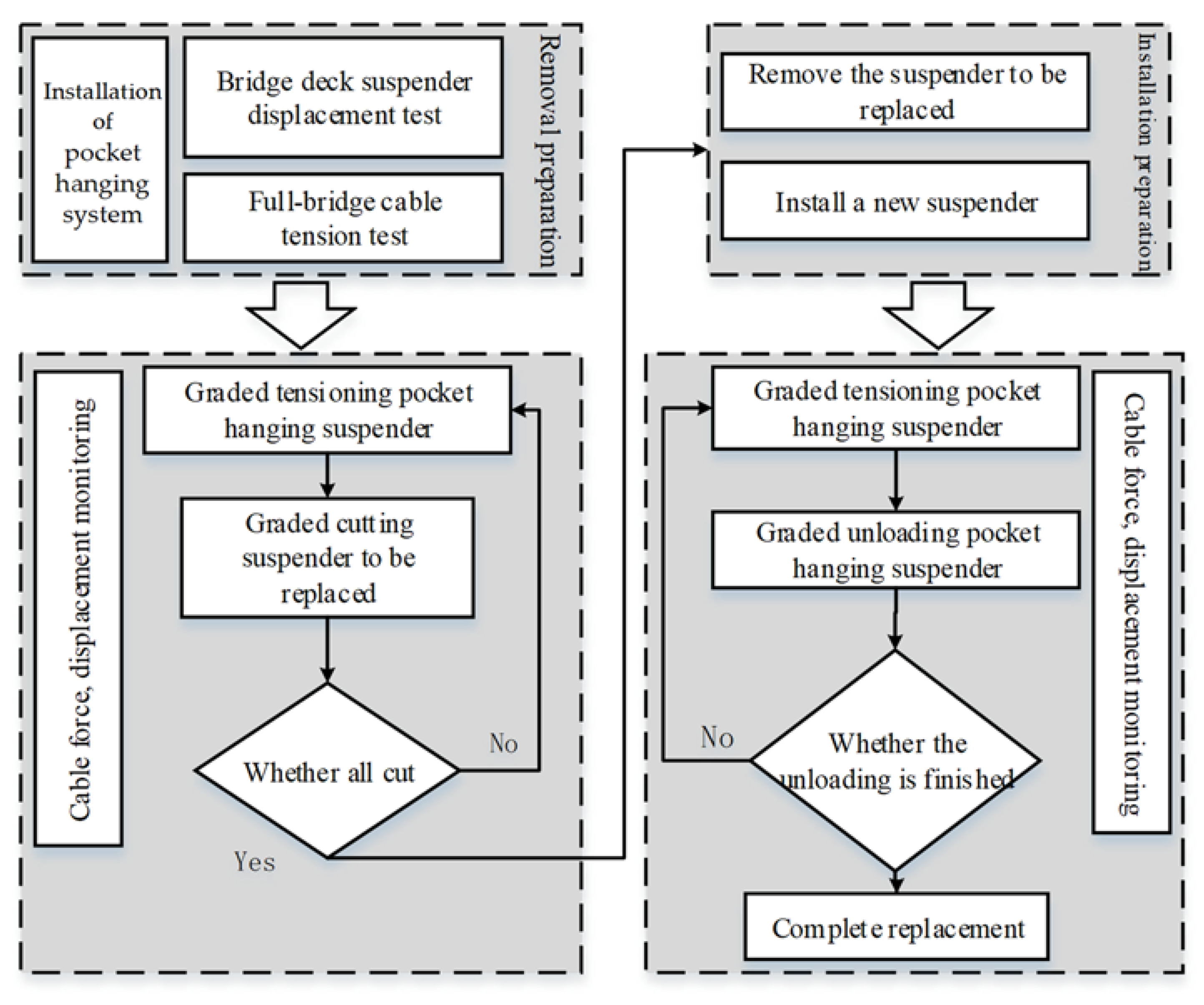
The principle of the pocket hanging method to replace a hanger is that the beam of the hanger at the place where the hanger is to be replaced is pocket hung directly on the arch rib by a wire rope, that is, the pocket hanging hanger, and then the steel wire is cut off in batches. Every time the wire is cut, the system should be properly repaired to balance the reduction of the cable force to be replaced. The new hanger is installed after removing and replacing the hanger, and the new hangers are tensioned and unloaded at different stages until the internal forces of the hangers are unloaded. The pocket hanging method is a kind of hanger replacement method which can change and improve the structure stress actively. The principle of “displacement control first, cable force control second” is followed in the hanger replacement process of half-through arches with a suspended deck by cable hangers. When the displacement is controlled within the range of resultant force, the cable force can be within a reasonable range. The hanger replacement process based on the pocket hanging method is shown in Figure 1. The precise control of displacement would be particularly important in the hanger replacement process of half-through arches by using the pocket hanging method [34,35].
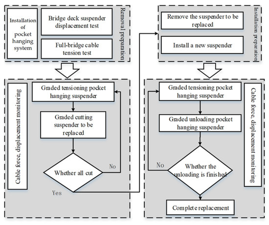
Figure 1.
The hanger replacement process based on the pocket hanging method.
2.1. Structural Equivalence
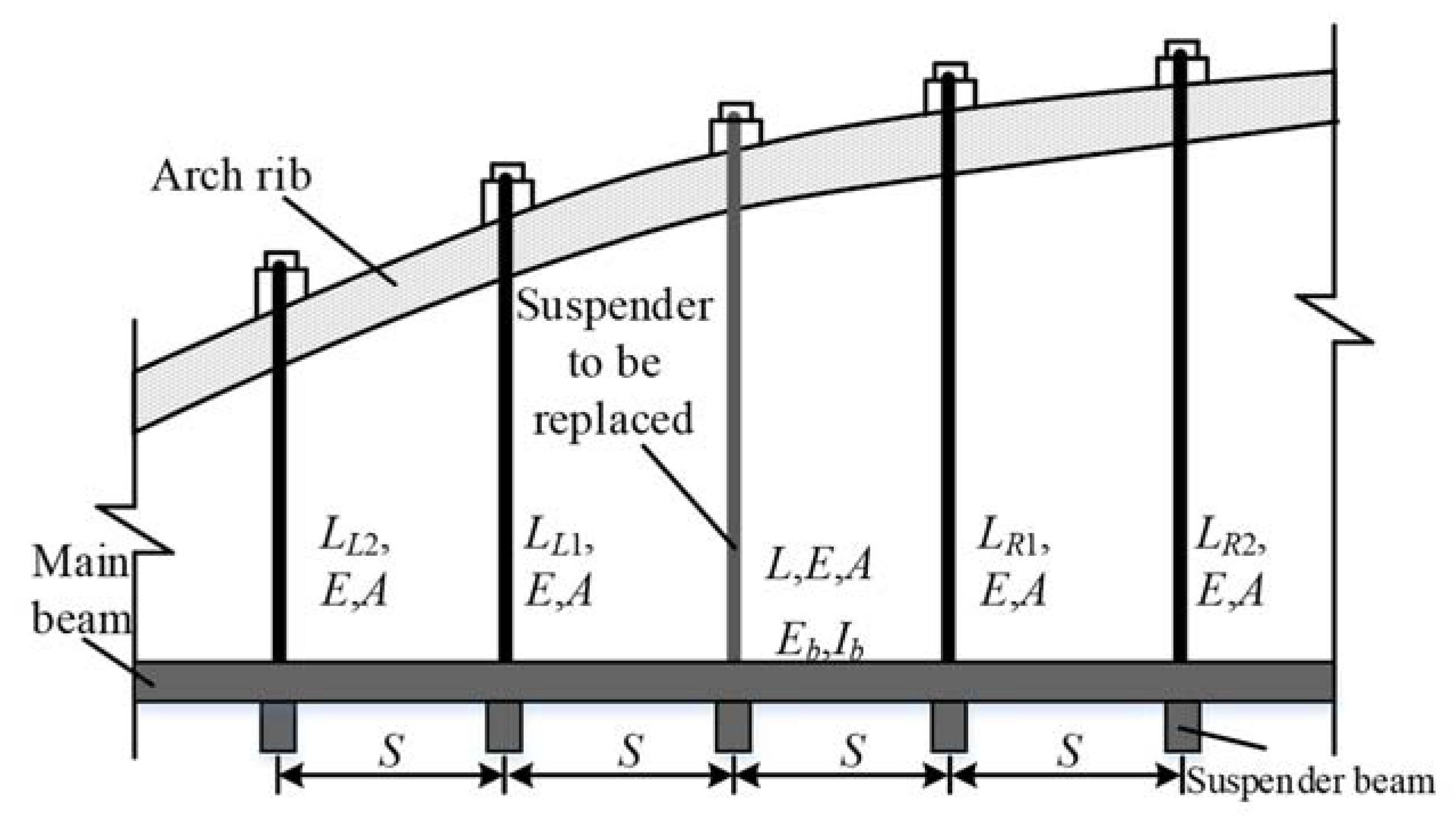
For the hanger arch bridge (as shown in Figure 2), the hanger elastic modulus is E, the section area is A, the hanger length is LLi and LRi (i = 1, 2, …), the length of the hanger to be replaced is L, the bending moment of inertia of the main beam is EbIb, and the spacing between the hanger is S.
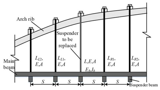
Figure 2.
Schematic diagram hanger arch bridge.
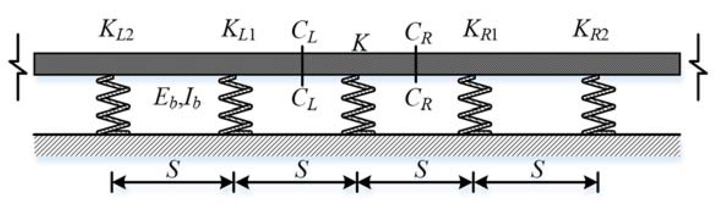
Since the stiffness of arch ribs is much greater than that of the hanger and bridge deck, the arch bridge girder can be equivalent to the multi-point elastic support continuous beam (as shown in Figure 3) in the hanger replacement process of half-through arches with a suspended deck by cable hangers. The spring stiffness on both sides of the hanger to be replaced is KLi and KRi (i = 1, 2, …) and the length of the hanger to be replaced is K. According to the principle of equivalent stiffness, the stiffness of the spring is:
where X = L or R, and i = 1, 2, ….
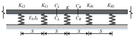
Figure 3.
Multi-point elastic supporting continuous beam.
The calculation is carried out when different numbers of hangers are left on both sides of the hanger to be replaced, and it is found that k is basically unchanged when three or more roots are left. With respect to the unit displacement applied downward to the lower end of the replaced hanger, the shear force k at the sections of CL and CR on both sides of the hanger to be replaced can be obtained by the displacement method. When different numbers of hangers are left on both sides of the hanger to be replaced, it is found that k is basically unchanged when three or more hangers are left. It is a fixed constraint for the main beam when two or more hangers are left on each side, so the deformation of the main beam is basically the same, while k is directly related to the deformation of the main beam. Therefore, k is as follows:
where
- .
It can be approximated that the length of each hanger is equal to that of the hanger to be replaced when the length of the hanger has little difference; thus, and can be expressed as follows:
2.2. Calculation of Hanger Removal Process
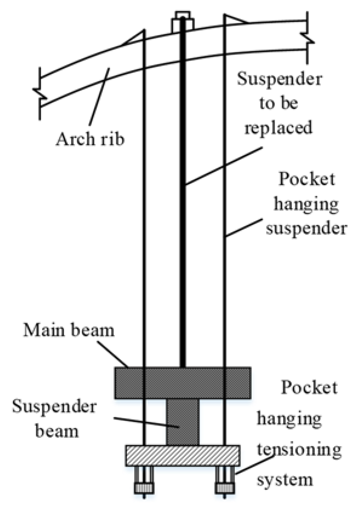
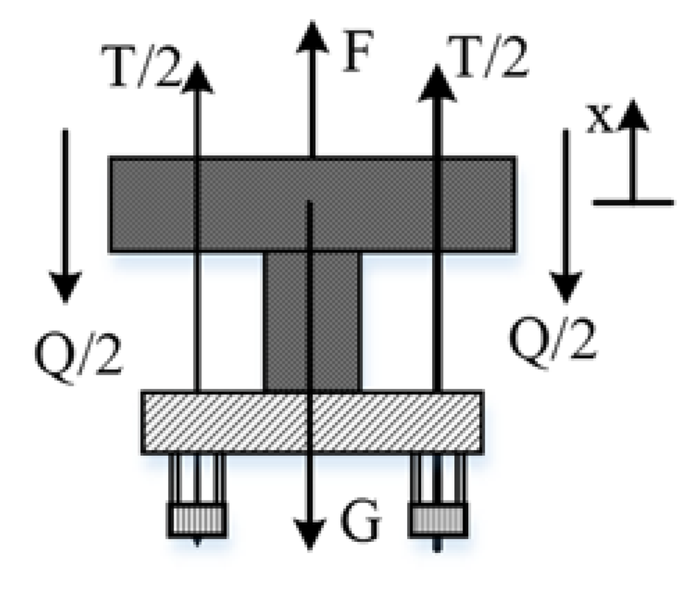
The hanger and some beam segments to be replaced can be taken out as shown in Figure 4 in the process of hanger removal. The upper end of the hanger can be fixed at the arch rib, and the lower end is connected to the pocket hanging tensioning system, which includes a jack to hold the cross beam, while the main beam takes the beam section between the sections of CL and CR on both sides of the hanger to be replaced. The stress on the main beam segment is shown in Figure 5, which is subject to the force F of the hanger to be replaced and the pocket hanging hanger force T, the shear force Q at the sections of CL and CR, and the resultant force G of the pocket hanging system weight and the dead weight of the main beam section. Next, the hanger removal process will be calculated take this beam section as an example.
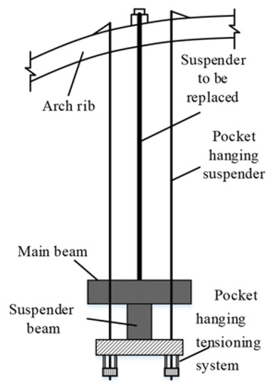
Figure 4.
Schematic diagram of the hanger and part of beam segment to be replaced.
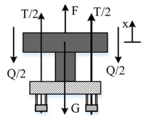
Figure 5.
Beam section force diagram during hanger removal.
2.2.1. Initial State
The initial state is the finished bridge state of half-through arches with a suspended deck by cable hangers before the hanger replacement:
(a) Old hanger: elastic modulus for E, cross section area of , and cable length L.
(b) Pocket hanging hanger: elastic modulus for , cross section area of , cable length , shear force , and cable force .
According to displacement coordination and force balance, it has:
2.2.2. The Time Pocket Hanging
Let the pocket hanging force be , the internal force of the old hanger be , the stress-free length of the pocket hanging hanger be , and the displacement in the process of the ith time pocket hanging be after the ith pocket hanging is done.
For the displacement of the lower end of the pocket hanging hanger, it has:
Similarly, for the lower end of the old hanger, we can obtain the following equation:
According to the equilibrium of forces:
where .
By combining Equations (7)–(9), the following equations can be obtained:
where .
2.2.3. The Time Cutting
Let the area of the old hanger be , the internal force of the pocket hanging hanger be , and the internal force and displacement of the old hanger be and , respectively, after the ith cutting of the old hanger is done.
The displacement of the lower end of the pocket hanging hanger satisfies the following equation:
Similarly, for the lower end of the old hanger, we can obtain:
According to the equilibrium of forces, it has:
where .
Combined with Equations (13)–(15), the following can be obtained:
where .
2.2.4. Displacement Control
According to the above calculation, the accumulative displacement of the lower end of the hanger to be replaced after the ith time pocket hanging is completed can be expressed as:
where is the Dirac function, that is:
The accumulative displacement of the lower end of the hanger to be replaced after the ith (i = 1, 2, …,) time cutting is completed can be expressed as:
and the control displacement threshold [D] need to satisfy the following relationship:
where the value of [D] is as follows:
2.3. Calculation of the New Hanger Installation Process
The installation of the new hanger is essentially the reverse process of the hanger removal. However, the tension process during the installation of the new hanger is the same as that of the unloading process, because the pocket hanging hanger is carried out through the jack pine oil without the need to cut it.
2.3.1. Initial State
The initial state is the state before the new hanger is installed:
(a) New hanger: elasticity modulus is , cross-sectional area is , and cable length is .
(b) Pocket hanging hanger: elasticity modulus is , cross-sectional area is , cable length is , shear force is , and cable tension is .
Since the new hanger is installed after the old hanger is removed, then there is:
According to the displacement coordination and force balance, it has:
2.3.2. The Times Tension of the New Hanger
After the ith times tension of the new hanger, let the new hanger internal force be , the pocket hanging hanger internal force be , the unstressed lengths of the new hanger and pocket hanging hanger be ,, respectively, and the displacement of the ith times tension of the new hanger be . There is no difference between this process and the ith times of the pocket hanging; therefore, the derivation is not repeated and there are:
where .
2.3.3. The Times Unloading of the Pocket Hanging Hanger
After the ith times unloading of the pocket hanging hanger, let the new hanger internal force be , the pocket hanging hanger internal force be , the unstressed lengths of the new hanger and pocket hanging hanger be ,, respectively, and the displacement of the ith times tension of the new hanger be .
where .
2.3.4. Displacement Control
Through the above calculation, it can be seen that after the ith times tension of the new hanger, the accumulative displacement of the lower end of the hanger is:
After the ith times unloading of the pocket hanging hanger, the accumulative displacement of the lower end of the hanger to be replaced is:
, , and control displacement threshold [D] need to satisfy the following relationship:
3. Case Study
A half-through concrete-filled steel tube truss arch bridge is shown in Figure 6, whose main clear span is 190 m, the rise-span ratio is 1/4.5, the arch axis is hingeless catenary, and the arch axis coefficient m = 1.167. An arch rib is a concrete-filled steel tube truss structure of the uniform section, and the cross section adopts φ820 × 12 mm and φ820 × 14 mm. The steel tubes form the top and bottom chord bar of the arch rib, and the section is 4.3 m high and 2.0 m wide. There are 27 hangers on each side of the main bridge, with an equal spacing of 5.1 m. The bridge was opened to traffic in December 2003, and there were some conditions such as a damaged sheath of the hanger, stagnant water at the anchor head, and a large deviation of the cable force of part of the hanger after 13 years of operation.
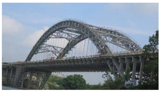
Figure 6.
Bridge elevation.
The bridge hangers were replaced in 2016 with the pocket hanging method and the upper and lower hangers were adopted as a pair to replace at the same time, which are composed of two φ60 mm steel-core wire ropes (6 × 37 S + IWR) symmetrically mounted on the arch rib, two I36b I-shaped steel pocket hanging beams, four sets of tension jacks, and QMV.DHM15-6 loose prevention anchorage with a low retraction anchor belt.
A vertical force of 1 KN was applied to the lower end of the hanger to be replaced (hanger #10), and the displacement of the bridge deck at the lower end of hanger #10 with different hangers on both sides of hanger #10 was calculated by the force method, as shown in Figure 7. The displacement of the bridge deck at the lower end of hanger #10 varied with the number of reserved hangers on both sides of hanger #10 as listed in Figure 7. It was found that when two or more hangers were left on both sides of hanger #10, the displacement of the bridge deck at the lower end of hanger #10 was basically unchanged through calculation. Therefore, only two hangers on each side of the hanger to be replaced can meet the process needs in practical application.
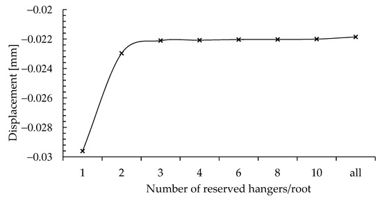
Figure 7.
The displacement of the bridge deck at the lower end of hanger #10 varying with the number of reserved hangers on both sides of hanger #10.
This study aimed to implement the hanger replacement procedure of pocket hanging described by a new method of displacement control, and the precise application procedure on the actual bridge is given as follows: Figure 8a shows the bridge deck test site at the displacement of the lower end of the hanger and Figure 8b shows the cable force test of the hanger. The influence of temperature is usually a difficult factor in the construction control. The temperature is changeable, which has an important influence on the stress and linearity of the bridge structure. Especially for the concrete-filled steel tubular arch bridge, the influence of temperature on the displacement is very significant. In this hanger replacement engineering application, temperature sensors were set to monitor the temperature of the bridge cross section, and the temperature simulation was carried out in the form of integral heating and uniform distribution in the finite element model.
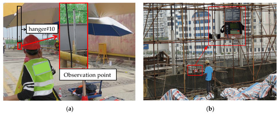
Figure 8.
The hanger replacement process by the pocket hanging method: (a) displacement measurement and (b) cable force test.
3.1. Old Hanger Demolition Process
The removal process of hanger #10 was calculated by the equations in Section 2.2. The pocket hanging and cutting processes were divided into five steps with the same step size, that is to say, the pocket hanging force of each stage increased by 20% of the internal force of the hanger to be replaced, and the cutting area of each stage was 20% of the area of the hanger to be replaced.
The displacement of the bridge deck at the lower end of the hanger and the arch rib displacement at the corresponding part of the hanger were monitored in the process of the hanger removal, in which the displacement of the lower end of the hanger was measured by a high precision Leica electronic level LS15 with a precision of 0.2 mm per kilometer round trip. The displacement of the arch rib at the corresponding point of the hanger was measured by a TS15A total station, with a test accuracy of 0.5 s, as shown in Figure 8a.
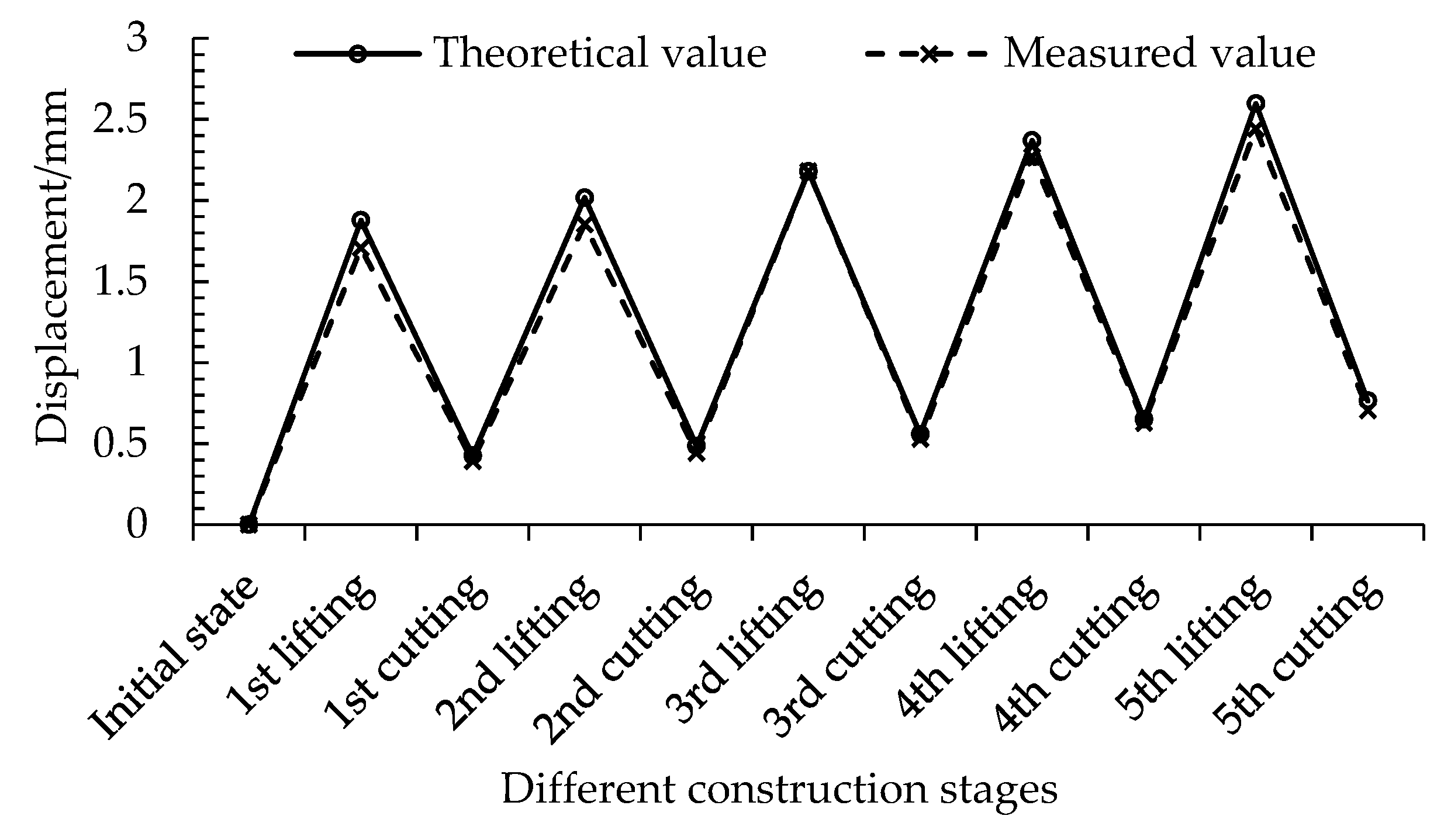
It was found that the displacement difference of the arch rib at the corresponding place of the hanger to be replaced was very small before and after the hanger was removed, less than 0.2 mm according to the displacement test results, which also verifies the correctness of the assumption that the arch rib has no deformation in the theoretical model in this paper. The test result of the bridge deck displacement at the lower end of the hanger to be replaced is exhibited in Figure 9. As can be observed in Figure 9, the displacement calculated in this paper is very close to the measured value, which verifies the correctness of the theoretical calculating method.
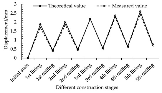
Figure 9.
Test results of bridge deck displacement at the lower end of the hanger to be replaced in different cases.
It can be seen from Table 1 that (1) the deformation of the main beam shares part of the pocket hanging force in the pocket hanging process, so that the change of the internal force of the hanger to be replaced was less than that of the pocket hanging force. (2) The internal force of the pocket hanging hanger was gradually increased, while the internal force of the hanger to be replaced was gradually reduced whether it was pocket hanging or cutting (see Figure 10), which is also the reason why the old hanger could be removed after only a few gradings by the pocket hanging method. (3) The displacement was upward when the pocket hanging was carried out, while it was downward when the cutting was carried out. Therefore, the cumulative displacement was small after a pocket hanging and cutting, and it can be seen that the maximum cumulative displacement after all levels of cutting was 0.77 mm. (4) Since the internal force of the cut wire is shared by the remaining wire when cutting, the downward displacement during cutting will always be less than the upward displacement during pocket hanging; as a result, the accumulated displacement after each cutting stage increased gradually, and the maximum cumulative displacement was 2.60 mm, which was less than that of threshold .

Table 1.
Calculation results of the removal process in different cases during the old hanger demolition process.
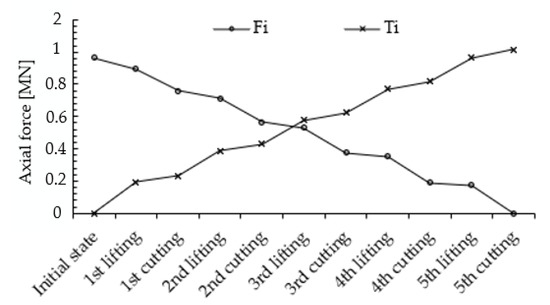
Figure 10.
The change of internal force of the pocket hanging hanger and the hanger to be replaced in different cases.
3.2. New Hanger Installation Process
The installation process of the new #10 hanger was calculated in five stages with the same step size based on the equations in Section 2.3, that is, the pocket hanging force and unloading force of each stage were 20% of the initial internal force of the pocket hanging hanger, whose calculated results are shown in Table 2 and Figure 11. The internal force was controlled by a hydraulic jack in the process of hanger tension and unloading force.
Table 2.
Calculation results of the removal process in different cases during the new hanger installation process.
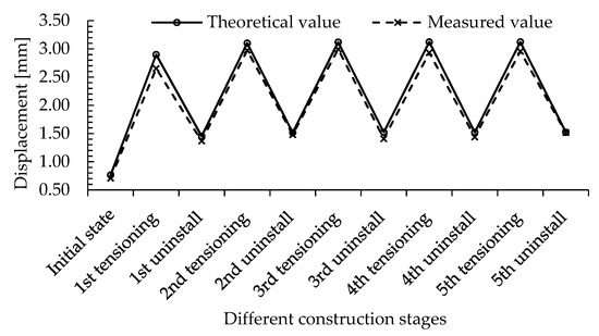
Figure 11.
Bridge deck displacement test results at the lower end of the new hanger in different cases.
It can be seen from Table 2 that the internal force increase of the new hanger was basically the same as the internal force decrease of the pocket hanging hanger after two rounds of tensioning and unloading, while the accumulative displacement showed an alternating trend of rise and fall, and the rise and fall were basically the same when the new hanger was installed by means of equal step length tensioning and unloading. The maximum accumulative displacement was 3.12 mm, which meets the requirements.
3.3. Compared with the FEM
In order to verify the practicability, convenience, and accuracy of the proposed method, the hanger replacement process of half-through arches with a suspended deck by cable hangers was also simulated by FEM. The three-dimensional finite element model was formed in Midas Civil (2018) as shown in Figure 12; the whole model consisted of 1786 nodal points, 80 truss elements, 2735 beam elements, and 370 plate elements. The hangers are represented with truss elements, the deck is described by plate elements, while others are represented with beam elements. The materials of the modal are listed in Table 3. In addition, the boundary conditions imposed on the end of the arch rib and the bottom of the pier in the model were all fixed constraints.
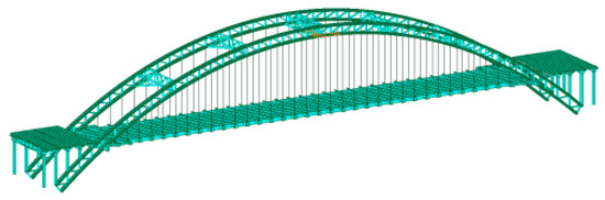
Figure 12.
Finite element model.
Table 3.
Materials of the model.
In the hanger replacement process of half-through arches with a suspended deck by cable hangers, there are two important steps: old hanger cutting and new hanger installation. The finite element simulation is as follows:
- (1)
- In the FEM, the cutting of the old hanger actually involves the simulation of the geometric nonlinearity. It is noted that the mentioned nonlinearity refers to the geometric nonlinearity caused by the cross-sectional area change of the hanger and the non-stress length change of the hanger in the hanger demolition and tension process. It is usually time-consuming to simulate the nonlinearity by the finite element method, and there is no good solution for the simulation of the non-stress length change of the hanger in the finite element method. However, the proposed method in this paper can not only accurately calculate the results, but is also more efficient.
- (2)
- In order to simplify, several repeated elements are usually established at the same position of the old hanger. These elements have the same parameters except the cross-sectional area. The cutting process of the old hanger is simulated by activating the hanger corresponding to the area of the construction stage in different construction stages and passivating the hanger of the previous construction stage. It is also important to note that the element needs to be activated along the initial tangential displacement of the member.
- (3)
- It is relatively easy to simulate the process of the installation of the new hanger because it does not involve the geometric nonlinearity of the structure. However, the method of external force replacement is needed when the temporary hanger force is transformed into the new hanger force. It is also noted that the hanger replacement implies a mutual effect in the side hangers. This is a linear effect, and a secondary effect of nonlinearity can depend only on the dissipative role of the attachments, joints, and operative methodologies, which is not considered in this study but will be discussed in a future study.
The finite element simulation was carried out on a T4900d-21 Lenovo microcomputer: the operating system was Windows 10 64 bit; the processor was a i7-7700, 4 core, 8 thread, 8 MB LEVEL 3 cache, and the highest frequency was 4.5 GHz; the memory model was a DDR4 with a capacity of 8.00 GB; and the video card model was an NVIDIA GeForce GT 730 with a capacity of 2048 MB and a RAMDAC frequency of 400 MHz.
The calculation results of the bridge deck displacement at the lower end of the hanger under different working conditions during the removal of the hanger and the installation of the new hanger are shown in Table 4 and Table 5, respectively. FMD = (FEM − Measured)/Measured × 100, PMD = (Present paper − Measured)/Measured × 100.
Table 4.
Calculation results of the bridge deck displacement at the lower end of the hanger under different working conditions during hanger removal.
Table 5.
Calculation results of the bridge deck displacement at the lower end of the hanger under different working conditions in the new hanger installation.
Through the calculation results, it can be seen that:
- (1)
- The trend of the finite element calculation results was basically consistent with the measured results, but the deviation between the measured and FEM results was still large, up to 10%. The main reason is that there were some differences in the material parameters and boundary conditions between the finite element model and the actual structure. However, if one wants to make the parameters in the finite element model consistent with the actual structural, a lot of field tests and calculation work would be required, so FEM is not conducive to engineering applications in simulating the hanger replacement process.
- (2)
- It took 55 min and 25 min, respectively, to remove the hanger and install the new hanger by the finite element simulation. However, only a small amount of calculation time was needed to use the proposed method. At the same time, the results calculated by this method were closer to the measured values than the FEM, and the maximum error was only -3.94%. Thus, it was proved that the proposed method is fast and accurate.
4. Conclusions
The precise displacement control of the bridge deck at the lower end of the hanger is very critical during the hanger replacement process of half-through arches with a suspended deck by cable hangers by using the pocket hanging method. The method of hanger replacement based on precise displacement control is proposed in this paper. Firstly, the variation coefficient of shear versus displacement on both sides of the hanger to be replaced were calculated and the hanger was separated from the overall model in order to establish the equivalent model of the hanger to be replaced. Secondly, the structural response of the hanger replacement process and the new hanger installation process were obtained on the basis of the equivalent model. Finally, an actual hanger replacement of an arch bridge was adopted to verify the correctness and feasibility of the proposed method. The following conclusions can be drawn:
- (1)
- The adopted equivalent model of hanger replacement by separating from the overall model in this paper was accurate, and only partial boundary conditions need to be considered in practical application to get accurate results.
- (2)
- In the hanger replacement process of an arch bridge based on the pocket hanging method, the cumulative displacement increased and decreased alternately, and the corresponding variation values were basically the same during the new hanger installation process using equal step tensioning and unloading, which would achieve a satisfactory result and meet the requirements.
- (3)
- Although the trend of the finite element calculation results was consistent with the measured results, the deviation between them was still large. By comparison, the calculated result using the proposed method were fast and accurate enough through the practical engineering verification, and the hanger replacement was feasible under the precise displacement control.
Author Contributions
Conceptualization, H.W., L.W. and X.W.; methodology, H.W., L.W. and W.W.; validation, X.Z. and K.H.; formal analysis, H.W., L.W. and X.W.; investigation, X.Z., K.H. and X.W.; writing—original draft preparation, H.W. and L.W.; writing—review and editing, X.W. and W.W.; project administration, H.W. and W.W.; funding acquisition, H.W. and W.W. All authors have read and agreed to the published version of the manuscript.
Funding
This research was sponsored by the Scientific and Technological Project of Science and Technology Department of Jilin Province (grant number: 20210508028RQ), Nanning Excellent Young Scientist Program (grant numbers: RC20180108 and RC20190206), the “Yongjiang Plan” of Nanning Leading Talents in Innovation and Entrepreneurship (grant number: 2018-01-04), and the Science and Technology Base and Talent Special Project of Guangxi Province (grant number: AD19245152). This research was also supported by the China Postdoctoral Science Foundation (grant number: 2021T140262).
Institutional Review Board Statement
Not applicable.
Informed Consent Statement
Not applicable.
Data Availability Statement
The data presented in this study are available on request from the corresponding author.
Acknowledgments
Thanks to Yuejing Luo for technical support.
Conflicts of Interest
The authors declare no conflict of interest.
References
- Zhang, D.Y.; Li, X.; Yan, W.M.; Xie, W.C.; Pandey, M.D. Stochastic seismic analysis of a concrete-filled steel tubular (CFST) arch bridge under tridirectional multiple excitations. Eng. Struct. 2013, 52, 355–371. [Google Scholar] [CrossRef]
- Usami, T.; Lu, Z.H.; Ge, H.B. A seismic upgrading method for steel arch bridges using buckling- restrained braces. Earthq. Eng. Struct. Dyn. 2005, 34, 471–496. [Google Scholar] [CrossRef]
- Xin, L.F.; Li, X.Z.; Zhang, Z.T.; Zhao, L.F. Seismic behavior of long-span concrete-filled steel tubular arch bridge subjected to near-fault fling-step motions. Eng. Struct. 2019, 180, 148–159. [Google Scholar] [CrossRef]
- Yang, K.K.; Yuan, J.; Shi, J.; Zheng, K.K.; Shen, J.Y. Stressing State Analysis on a Single Tube CFST Arch Under Spatial Loads. Appl. Sci. 2019, 9, 5039. [Google Scholar] [CrossRef] [Green Version]
- Liu, H.B.; Wang, L.L.; Tan, G.J.; Cheng, Y.C. An Adjusting Method for the Suspender Force of Continuous Beam Arch Combination Bridge Based on Influence Matrix. Appl. Mech. Mater. 2013, 275–277, 1082–1085. [Google Scholar] [CrossRef]
- Liu, Z.X.; Guo, T.; Huang, L.Y.; Pan, Z.H. Fatigue Life Evaluation on Short Suspenders of Long-Span Suspension Bridge with Central Clamps. J. Bridge Eng. 2017, 22, 04017074. [Google Scholar] [CrossRef]
- Zhao, H.W.; Ding, Y.L.; An, Y.H.; Li, A.Q. Transverse Dynamic Mechanical Behavior of Hangers in the Rigid Tied-Arch Bridge under Train Loads. J. Perform. Constr. Facil. 2017, 31, 04016072. [Google Scholar] [CrossRef]
- Bouaanani, N. Numerical investigation of the modal sensitivity of suspended cables with localized damage. J. Sound Vib. 2006, 292, 1015–1030. [Google Scholar] [CrossRef]
- Li, S.L.; Hu, P.Y.; Zhao, X.F.; Chen, K.J.; Li, J.K. Atmospheric corrosion performance of wire rope sling in a sulfur dioxide-polluted environment. Adv. Mech Eng. 2017, 9, 1687814017707479. [Google Scholar] [CrossRef] [Green Version]
- Mehrabi, A.B.; Ligozio, C.A.; Ciolko, A.T.; Wyatt, S.T. Evaluation, Rehabilitation Planning, and Stay-Cable Replacement Design for the Hale Boggs Bridge in Luling, Louisiana. J. Bridge Eng. 2010, 15, 364–372. [Google Scholar] [CrossRef]
- Lan, R.Y.; Jiang, G.F.; Wang, H.; Hao, T.Z.; Wang, L.L.; Liang, Q.X. Research on the Suspender Replacement Process of Arch Bridge Based on the Measured Displacement Correction. IEEE Access 2020, 8, 226952–226961. [Google Scholar] [CrossRef]
- Sun, Z.; Ning, S.W.; Shen, Y.F. Failure Investigation and Replacement Implementation of Short Suspenders in a Suspension Bridge. J. Bridge Eng. 2017, 22, 05017007. [Google Scholar] [CrossRef]
- Li, S.L.; Zhu, S.Y.; Xu, Y.L.; Chen, Z.W.; Li, H. Long-term condition assessment of suspenders under traffic loads based on structural monitoring system: Application to the Tsing Ma Bridge. Struct. Control. Health Monit. 2012, 19, 82–101. [Google Scholar] [CrossRef]
- Feng, D.M.; Mauch, C.; Summerville, S.; Fernandez, O. Suspender Replacement for a Signature Bridge. J. Bridge Eng. 2018, 23, 05018010. [Google Scholar] [CrossRef]
- Fu, Z.Q.; Ji, B.H.; Yang, M.Y.; Sun, H.B.; Maeno, H. Cable Replacement Method for Cable-Stayed Bridges Based on Sensitivity Analysis. J. Perform. Constr. Facil. 2015, 29, 04014085. [Google Scholar] [CrossRef]
- Crespi, P.; Zucca, M.; Valente, M. On the collapse evaluation of existing RC bridges exposed to corrosion under horizontal loads. Eng. Fail. Anal. 2020, 116, 104727. [Google Scholar] [CrossRef]
- Bossio, A.; Fabbrocino, F.; Monetta, T.; Lignola, G.P.; Prota, A.; Manfredi, G.; Bellucci, F. Corrosion effects on seismic capacity of reinforced concrete structures. Corros. Rev. 2019, 37, 45–56. [Google Scholar] [CrossRef]
- Zhuang, D.; Xiao, R.; Jia, L.; Sun, B. Failure analysis for overall stability against sliding and overturning of a girder bridge. Eng. Fail. Anal. 2020, 109, 104271. [Google Scholar] [CrossRef]
- Crespi, P.; Zucca, M.; Longarini, N.; Giordano, N. Seismic Assessment of Six Typologies of Existing RC Bridges. Infrastructures 2020, 5, 52. [Google Scholar] [CrossRef]
- Liu, Z.X.; Guo, T.; Hebdon, M.H.; Zhang, Z.L. Corrosion Fatigue Analysis and Reliability Assessment of Short Suspenders in Suspension and Arch Bridges. J. Perform. Constr. Facil. 2018, 32, 04018060. [Google Scholar] [CrossRef]
- Xiaomei, S.; Hongsheng, X.; Donghuang, Y. Optimization Research of Construction Process in Hanger Replacement of Arch Bridge without Interrupting Traffic. J. China Foreign Highw. 2019, 39, 107–111. [Google Scholar]
- Hossain, I.; Sluszka, P. Suspension bridge cable replacement. IABSE Symp. Rep. 2004, 88, 7–12. [Google Scholar]
- Ferreira, F.; Simoes, L. Automated synthesis of controlled cable-stayed footbridges with S-shaped deck. Adv. Eng. Softw 2020, 149, 102881. [Google Scholar] [CrossRef]
- Ferreira, F.; Simoes, L. Synthesis of three dimensional controlled cable-stayed bridges subject to seismic loading. Comput. Struct. 2020, 226, 106137. [Google Scholar] [CrossRef]
- Martins, A.M.B.; Simoes, L.M.C.; Negrao, J.H.J.O. Optimum design of concrete cable-stayed bridges. Eng. Optim. 2016, 48, 772–791. [Google Scholar] [CrossRef]
- Yao, W.J.; Yang, W.; Liu, X.Y. Analysis the Cable Replacement Method of Tianjin Yonghe Bridge. Appl. Mech. Mater. 2011, 71–78, 1383–1387. [Google Scholar] [CrossRef]
- Quansheng, S.; Haiying, Y.; Xiaoguang, G.; Jiawei, W.; Tong, W. Application of Kalman’s filtering method in construction control for cable replacement of the cable-stayed bridge. In Proceedings of the 2010 International Conference on Electrical and Control Engineering, Wuhan, China, 25–27 June 2010. [Google Scholar]
- Brown, J.L. Louisiana span set for complete cable replacement. Civ. Eng. 2008, 78, 24–27. [Google Scholar]
- Granata, M.F.; Arici, M.; Longo, G.; Recupero, A. Steel and composite tied-arch bridges: A conceptual approach to structural design. Proc. Inst. Civ. Eng.-Bridge Eng. 2021. [Google Scholar] [CrossRef]
- Recupero, A.; Granata, M.F. A Mixed Approach for Determination of Initial Cable Forces in Cable-Stayed Bridges and the Parameters Variability. Balt. J. Road Bridge Eng. 2015, 10, 141–150. [Google Scholar] [CrossRef]
- Granata, M.F.; Longo, G.; Recupero, A.; Arici, M. Construction sequence analysis of long-span cable-stayed bridges. Eng. Struct. 2018, 174, 267–281. [Google Scholar] [CrossRef]
- Granata, M.F.; Margiotta, P.; Recupero, A.; Arici, M. Partial Elastic Scheme Method in Cantilever Construction of Concrete Arch Bridges. J. Bridge Eng. 2013, 18, 663–672. [Google Scholar] [CrossRef]
- Mellier, E.; Joye, S.; Maillet, V. High Level Engineering for Stay Cable Replacement. IABSE Symp. Rep. 2009, 96, 230–239. [Google Scholar]
- Saeed, N.M.; Kwan, A.S.K. Displacement and internal force control in cable-stayed bridges. Proc. Inst. Civ. Eng.-Bridge Eng. 2018, 171, 63–76. [Google Scholar] [CrossRef]
- Setiadji, B.H.; Trong Nguyen, V.; Choi, Y.-W.; Yoon, J.-I.; Choi, K.-H.; Son, C.-H.; Kim, Y.-B.; Han, A.L.; Widodo, A.; Setiawan, J.D.; et al. Modeling, Identification, and Simulation of Positional Displacement Control for Ribbon Bridges. MATEC Web Conf. 2018, 159, 02026. [Google Scholar]


Publisher’s Note: MDPI stays neutral with regard to jurisdictional claims in published maps and institutional affiliations. |
© 2021 by the authors. Licensee MDPI, Basel, Switzerland. This article is an open access article distributed under the terms and conditions of the Creative Commons Attribution (CC BY) license (https://creativecommons.org/licenses/by/4.0/).