
Large-Scale Simulation of Full Three-Dimensional Flow and Combustion of an Aero-Turbofan Engine on Sunway TaihuLight Supercomputer
 and
and
Abstract
1. Introduction
2. Current State of the Art
2.1. Simulation of the Aeroengine
2.2. PDE Solvers
3. Sunway TaihuLight and the Innovative Methods
3.1. System Overview of Sunway TaihuLight
3.2. The SW26010 Processor
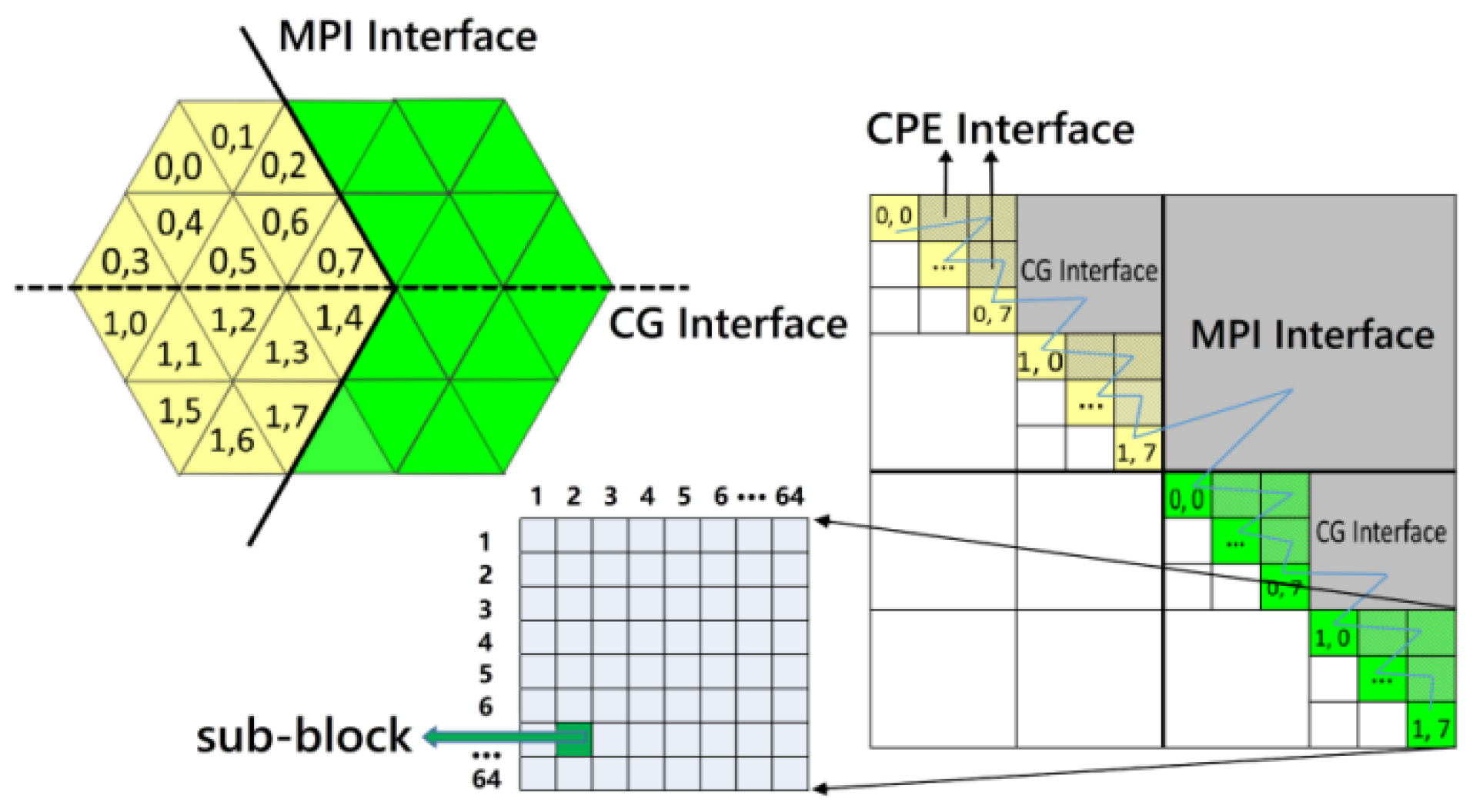
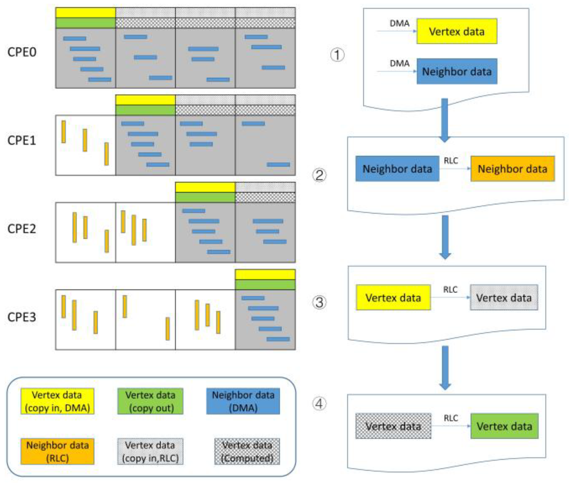
3.3. AMI Parallelization
3.4. Performance Challenges
- memory bandwidth limited
- irregular memory access
- the tradeoff between parallelism and converging speed
- large-scale aeroengine simulation toolchain shortage
3.5. A Customized Parallelization Design [29]
| Algorithm 1. Register-Level Communication |
| 1: define SPE_NUMS 64 2: for i = 1->SPE_NUMS do 3: bias[i] = 0 4: end for 5: for ipcg = 1–>total_send_pcg do 6: if (MYID> sPacks[ipcg].dst_id) then 7: edge_id = edge_start[sPacks[ipcg].dst_id] 8: + bias[sPacks[ipcg].dst_id] 9: sPacks[ipcg].data <– x[Neighbor[edge_id]] 10: bias[sPacks[ipcg].dst_id]++ 11: end if 12: end for 13: reg_transfer_data() 14: for ipcg = 1–>total_recv_pcg do 15: if (MYID > rPacks[ipcg].src_id) then 16: x[length] <– rPacks[ipcg].data 17: length++ 18: end if 19: end for |
3.6. Efficient Linear Solving: Multilevel Parallelism
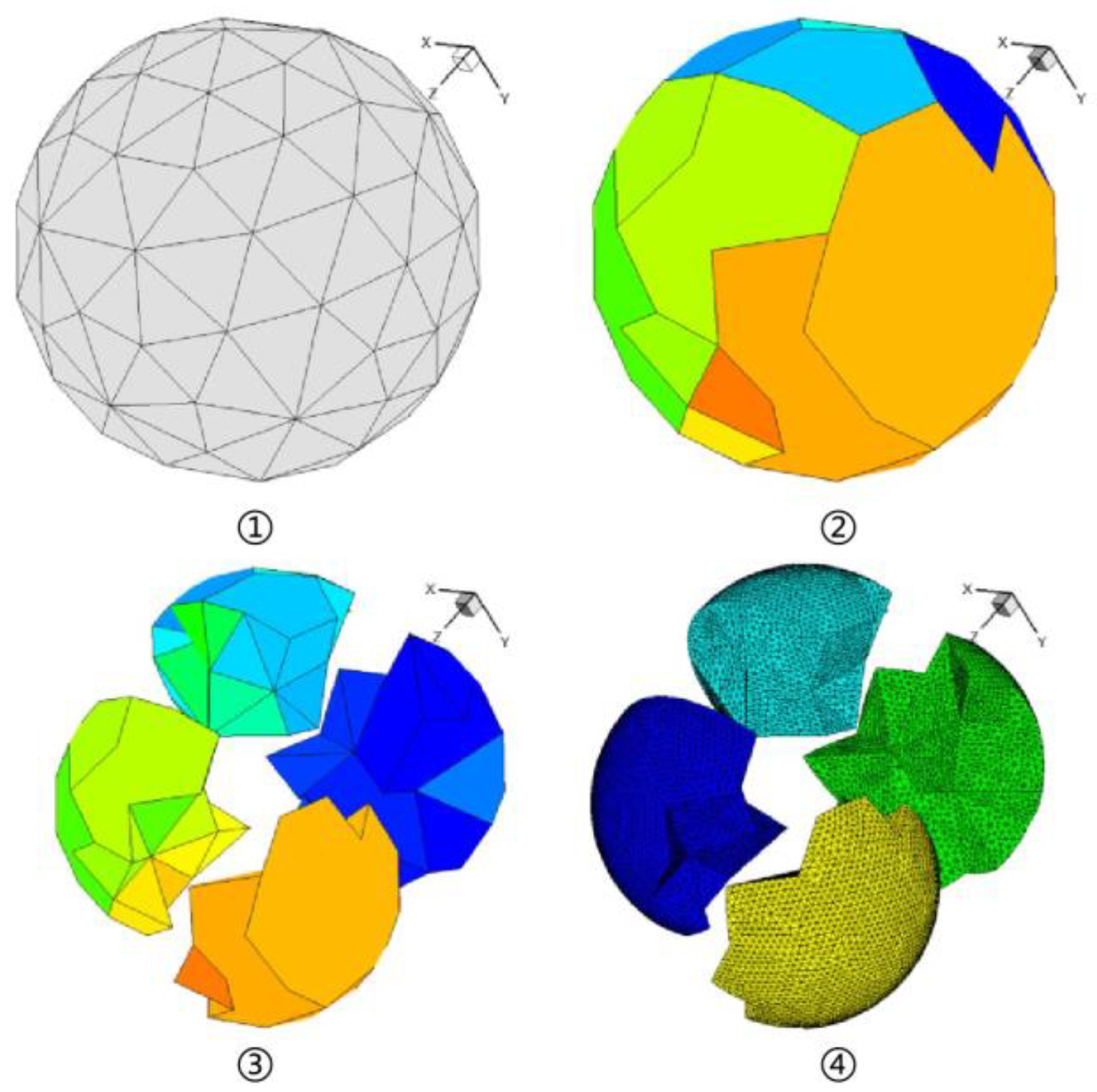
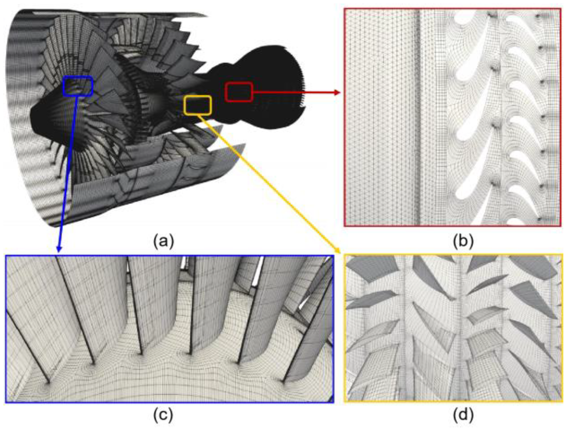
3.7. Parallel Mesh Generation
4. Performance Tests and the Results
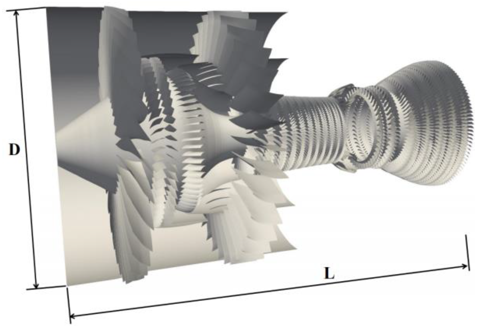
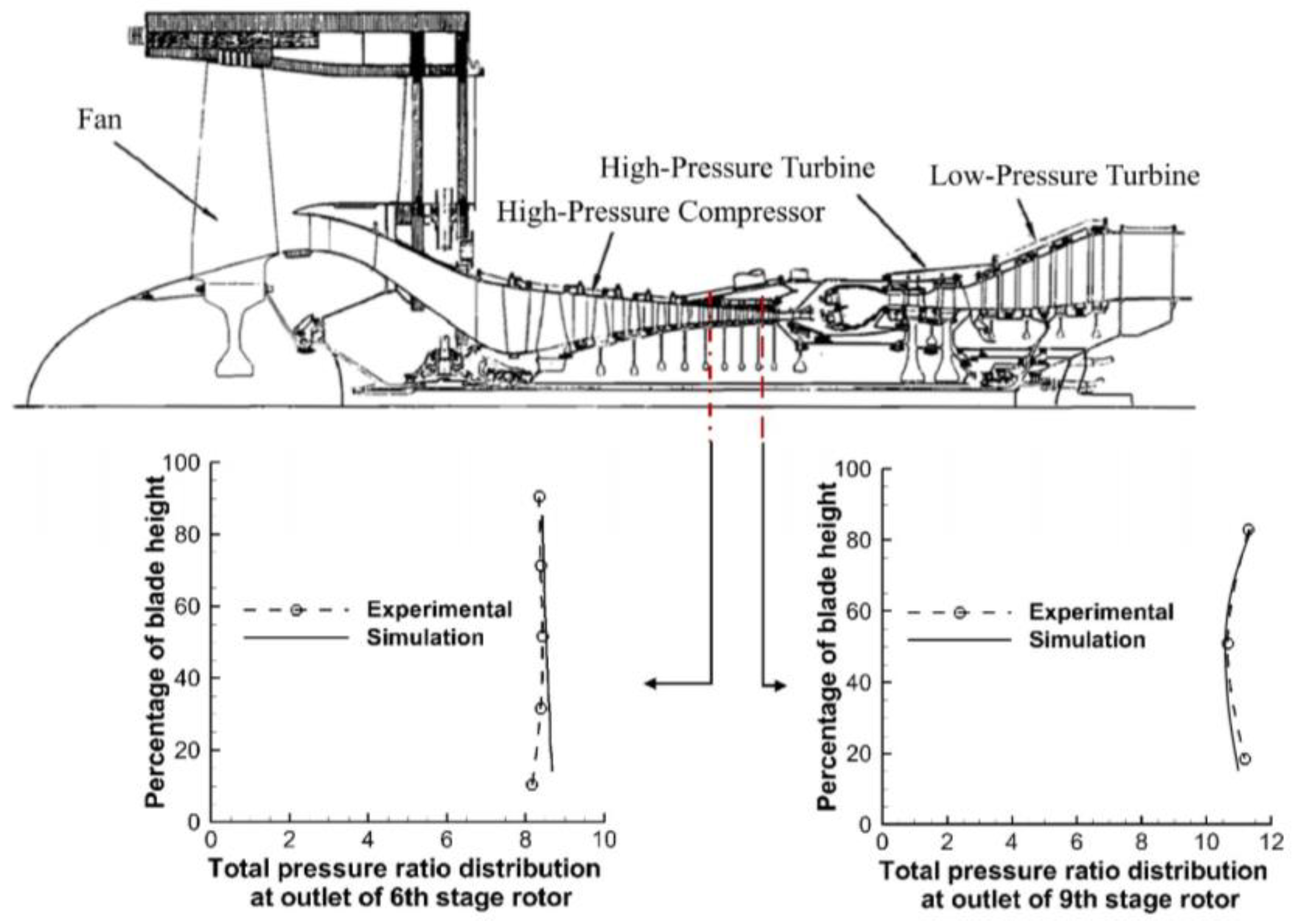
4.1. Model and Settings
- (a)
- Physics Runs
- (b)
- Peak Sustained Performance Runs
- (c)
- Scaling Runs
4.2. Performance Results
- (a)
- Scaling
- (b)
- Peak Sustained Performance
- (c)
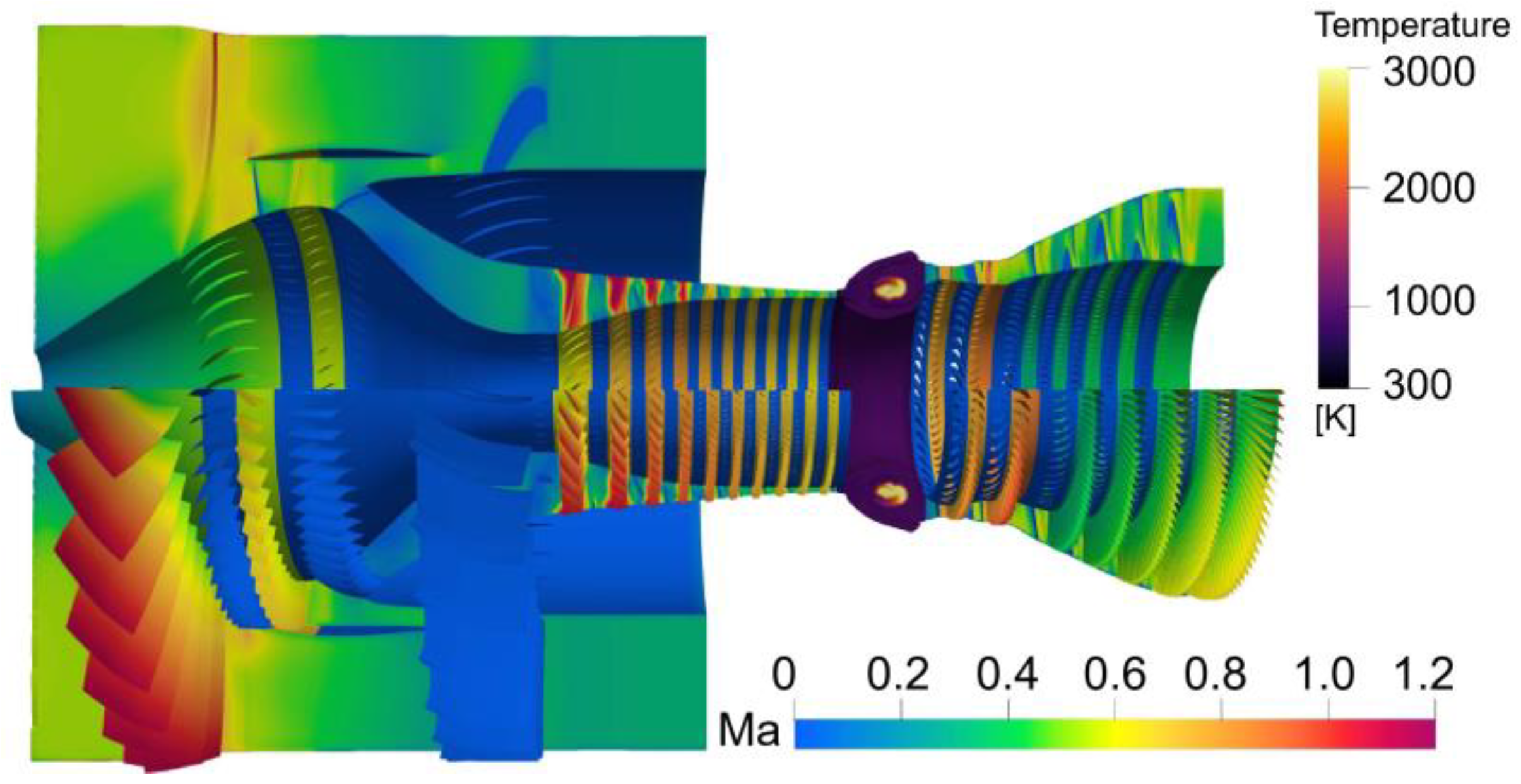
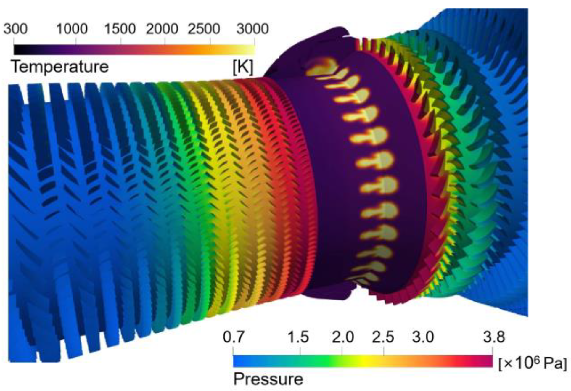
- Physics
4.3. Implications
- (a)
- High-Confidence Computing
- (b)
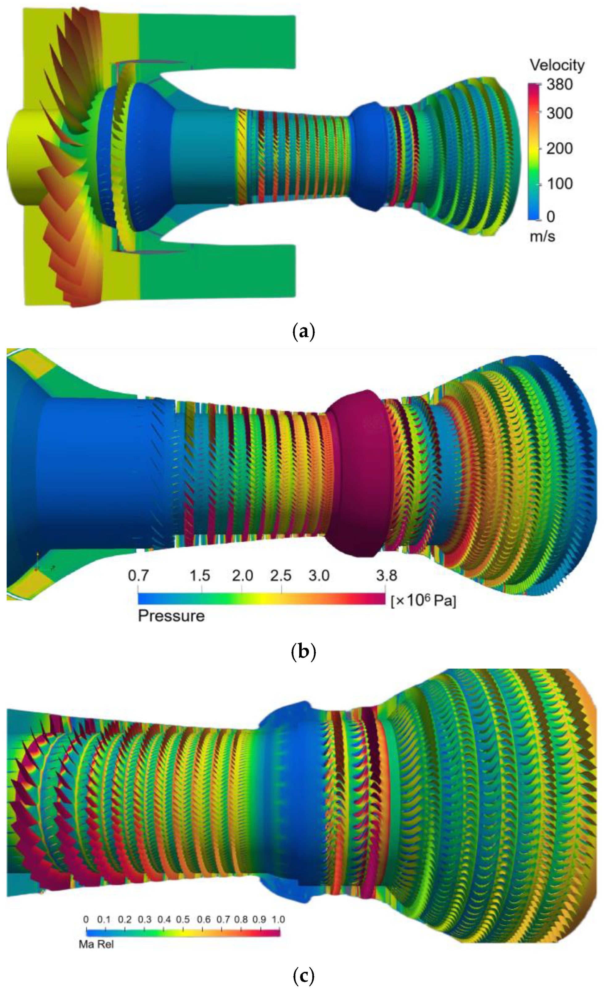
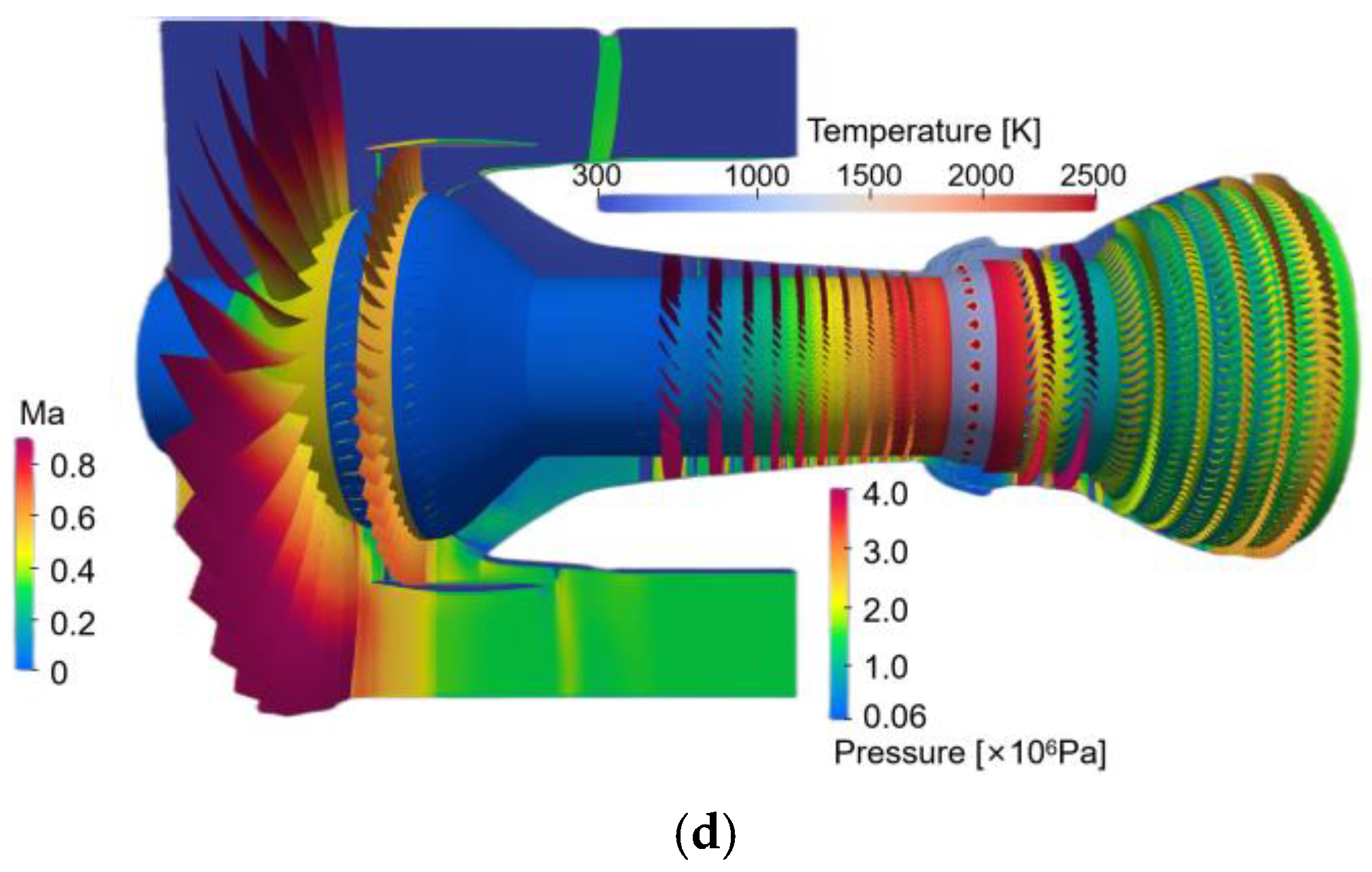
- Capture the Complex Phenomenon
- (c)
- Reduce the Time in Engine Development
- (d)
- Reduce the cost
5. Conclusions
- The efficient implicit solver ‘sprayDyMFoam’ for an unstructured mesh developed in this paper can be effectively applied to the simulation of full three-dimensional flow and combustion on the whole aeroengine, and the performance of the whole machine can match well with the test.
- An efficient mesh generation method is adopted by transplanting an in-house parallel unstructured meshing code onto Sunway TaihuLight, and the practices have proved the ability to generate billions of mesh elements in dozens of minutes.
- By adjusting the droplet atomization model, the rules of droplet motion are optimized, and the conflict between large-scale parallelization and the Lagrangian module can be solved. Meanwhile, the adjustment of the PIMPLE algorithm in aerodynamic solution also improves the solution accuracy.
- The traditional parallel communication mechanism of AMI boundary processing is optimized, which effectively solves the parallel bottleneck of AMI and improves the calculation efficiency.
- The research carried out in this paper can be applied in high-confidence computing, the complex phenomenon capturing, and time and cost reduction in aeroengine design.
Author Contributions
Funding
Institutional Review Board Statement
Data Availability Statement
Conflicts of Interest
References
- Skira, C.A. Reducing Military Aircraft Engine Development Cost through Modeling and Simulation; Air Force Research Lab Wright-Patterson AFB OH Turbine Engine Division: Wright-Patterson AFB, OH, USA, 2003. [Google Scholar]
- Wang, H.; Liu, B.; Mao, X.; Zhang, B.; Yang, Z. Combined flow control strategy investigation for corner separation and mid-span boundary layer separation in a high-turning compressor cascade. Entropy 2022, 24, 570. [Google Scholar] [CrossRef] [PubMed]
- Singh, T.S.; Rajak, U.; Dasore, A.; Muthukumar, M.; Verma, T.N. Performance and ecological parameters of a diesel engine fueled with diesel and plastic pyrolyzed oil (PPO) at variable working parameters. Environ. Technol. Innov. 2021, 22, 101491. [Google Scholar] [CrossRef]
- Potier, L.; Duchaine, F.; Cuenot, B.; Saucereau, D.; Pichillou, J. Prediction of Wall Heat Fluxes in a Rocket Engine with Conjugate Heat Transfer Based on Large-Eddy Simulation. Entropy 2022, 24, 256. [Google Scholar] [CrossRef] [PubMed]
- Kesharvani, S.; Dwivedi, G.; Verma, T.N.; Verma, P. The experimental investigation of a diesel engine using ternary blends of algae biodiesel, ethanol and diesel fuels. Energies 2023, 16, 229. [Google Scholar] [CrossRef]
- Medic, G.; Kalitzin, G.; You, D.; van der Weide, E.; Alonso, J.; Pitsch, H. Integrated rans/les computations of an entire gas turbine jet engine. In Proceedings of the 45th AIAA Aerospace Sciences Meeting and Exhibit, Reno, NV, USA, 8–11 January 2007. [Google Scholar]
- Turner, M. Lessons learned from the ge90 3-d full engine simulations. In Proceedings of the 48th AIAA Aerospace Sciences Meeting Including the New Horizons Forum and Aerospace Exposition, Orlando, FL, USA, 4–7 January 2010. [Google Scholar]
- Wang, F. Whole Aero-Engine Meshing and CFD Simulation. Ph.D. Dissertation, Imperial College London, London, UK, 2013. [Google Scholar]
- Krivcov, A.V.; Shabliy, L.S.; Baturin, O.V. Gas-dynamic modeling of gas turbine engine components collaborative workflow. Open Mech. Eng. J. 2014, 8, 445–449. [Google Scholar] [CrossRef]
- Teixeira, M.; Romagnosi, L.; Mezine, M.; Baux, Y.; Anker, J.; Claramunt, K.; Hirsch, C. A methodology for fully-coupled cfd engine simulations, applied to a micro gas turbine engine. In Proceedings of the Turbo Expo: Power for Land, Sea, and Air; American Society of Mechanical Engineers: New York, NY, USA, 2018; Volume 51012, p. V02CT42A047. [Google Scholar]
- Pérez Arroyo, C.; Dombard, J.; Duchaine, F.; Gicquel, L.; Odier, N.; Exilard, G.; Richard, S.; Buffaz, N.; Démolis, J. Large-eddy simulation of an integrated high-pressure compressor and combustion chamber of a typical turbine engine architecture. In Proceedings of the ASME Turbo Expo 2020: Turbomachinery Technical Conference and Exposition; American Society of Mechanical Engineers: New York, NY, USA, 2020. [Google Scholar]
- Zhang, J.; Wei, G.; Huang, W. Three-dimensional simulation of a core engine. Gas Turbine Exp. Res. 2020, 33, 1–5. (In Chinese) [Google Scholar]
- Weller, H.G.; Tabor, G.; Jasak, H.; Fureby, C. A tensorial approach to computational continuum mechanics using object-oriented techniques. Comput. Phys. 1998, 12, 620–631. [Google Scholar] [CrossRef]
- Tiwari, C.; Verma, T.N.; Dwivedi, G.; Verma, P. Energy-exergy analysis of diesel engine fueled with microalgae biodiesel-diesel blend. Appl. Sci. 2023, 13, 1857. [Google Scholar] [CrossRef]
- Boileau, M.; Staffelbach, G.; Cuenot, B.; Poinsot, T.; Bérat, C. Les of an ignition sequence in a gas turbine engine. Combust Flame 2008, 154, 2–22. [Google Scholar] [CrossRef]
- Moriai, H.; Hori, K.; Kurose, R.; Komori, S. Large-eddy simulation of spray combution in a sector combustor for regional jet aircraft engine-effect of double-wall liner on nox formation. In Proceedings of the Ninth International Symposium on Turbulence and Shear Flow Phenomena, Melbourne, Australia, 30 June–3 July 2015. [Google Scholar]
- Moureau, V.; Domingo, P.; Vervisch, L. Design of a massively parallel CFD code for complex geometries. C. R. Mécanique 2011, 339, 141–148. [Google Scholar] [CrossRef]
- Bisetti, F.; Attili, A.; Pitsch, H. Advancing predictive models for particulate formation in turbulent flames via massively parallel direct numerical simulations. Philos. Trans. R. Soc. A 2014, 372, 20130324. [Google Scholar] [CrossRef] [PubMed]
- Tachibana, S.; Saito, K.; Yamamoto, T.; Makida, M.; Kitano, T.; Kurose, R. Experimental and numerical investigation of thermo-acoustic instability in a liquid-fuel aero-engine combustor at elevated pressure: Validity of large-eddy simulation of spray combustion. Combust Flame 2015, 162, 2621–2637. [Google Scholar] [CrossRef]
- Shen, Y.; Zhang, K.; Duwig, C. Investigation of wet ammonia combustion characteristics using LES with finite-rate chemistry. Fuel 2022, 311, 122422. [Google Scholar] [CrossRef]
- Mirin, A.A.; Cohen, R.H.; Curtis, B.C.; Dannevik, W.P.; Dimits, A.M.; Duchaineau, M.A.; Eliason, D.E.; Schikore, D.R.; Anderson, S.E.; Porter, D.H.; et al. Very high resolution simulation of compressible turbulence on the IBM-SP system. In Proceedings of the 1999 ACM/IEEE Conference on Supercomputing, Portland, OR, USA, 11–14 November 1999. [Google Scholar]
- Shingu, S.; Takahara, H.; Fuchigami, H.; Yamada, M.; Tsuda, Y.; Ohfuchi, W.; Sasaki, Y.; Kobayashi, K.; Hagiwara, T.; Habata, S.I.; et al. A 26.58 Tflops global atmospheric simulation with the spectral transform method on the Earth Simulator. In Proceedings of the 2002 ACM/IEEE Conference on Supercomputing, Baltimore, MD, USA, 16–22 November 2002. [Google Scholar]
- Adams, M.F.; Bayraktar, H.H.; Keaveny, T.M.; Papadopoulos, P. Ultrascalable implicit finite element analyses in solid mechanics with over a half a billion degrees of freedom. In Proceedings of the 2004 ACM/IEEE Conference on Supercomputing, Pittsburgh, PA, USA, 6–12 November 2004. [Google Scholar]
- Shimokawabe, T.; Aoki, T.; Takaki, T.; Endo, T.; Yamanaka, A.; Maruyama, N.; Nukada, A.; Matsuoka, S. Peta-scale phase-field simulation for dendritic solidification on the tsubame 2.0 supercomputer. In Proceedings of the 2011 International Conference for High Performance Computing, Networking, Storage and Analysis, Seatle, WA, USA, 12–18 November 2011. [Google Scholar]
- Rossinelli, D.; Hejazialhosseini, B.; Hadjidoukas, P.; Bekas, C.; Curioni, A.; Bertsch, A.; Futral, S.; Schmidt, S.J.; Adams, N.A.; Koumoutsakos, P. 11 p-op/s simulations of cloud cavitation collapse. In Proceedings of the International Conference on High Performance Computing, Networking, Storage and Analysis, Denver, CO, USA, 19–26 April 2013. [Google Scholar]
- Rudi, J.; Malossi, A.C.I.; Isaac, T.; Stadler, G.; Gurnis, M.; Staar, P.W.; Ineichen, Y.; Bekas, C.; Curioni, A.; Ghattas, O. An extreme-scale implicit solver for complex pdes: Highly heterogeneous flow in earth’s mantle. In Proceedings of the International Conference for High Performance Computing, Networking, Storage and Analysis, Austin, TX, USA, 15–20 November 2015. [Google Scholar]
- Yang, C.; Xue, W.; Fu, H.; You, H.; Wang, X.; Ao, Y.; Liu, F.; Gan, L.; Xu, P.; Wang, L.; et al. 10m-core scalable fully-implicit solver for nonhydrostatic atmospheric dynamics. In Proceedings of the International Conference for High Performance Computing, Networking, Storage and Analysis, Denver, CO, USA, 17–19 November 2019. [Google Scholar]
- Fang, J.; Fu, H.; Zhao, W.; Chen, B.; Zheng, W.; Yang, G. swdnn: A library for accelerating deep learning applications on sunway taihulight. In Proceedings of the 2017 IEEE International Parallel and Distributed Processing Symposium (IPDPS), Orlando, FL, USA, 29 May–2 June 2017. [Google Scholar]
- Liu, H.; Ren, H.; Gu, H.; Gao, F.; Yang, G. Unat: Unstructured acceleration toolkit on sw26010 many-core processor. Eng. Comput. 2020, 37, 3187–3208. [Google Scholar] [CrossRef]
- Adams, M.; Brezina, M.; Hu, J.; Tuminaro, R. Parallel multigrid smoothing: Polynomial versus gauss–seidel. J. Comput. Phys. 2003, 188, 593–610. [Google Scholar] [CrossRef]
- Scales, J.A. On the use of conjugate gradient to calculate the eigenvalues and singular values of large, sparse matrices. Geophys. J. Int. 1989, 97, 179–183. [Google Scholar] [CrossRef]
- Ghysels, P.; Vanroose, W. Hiding global synchronization latency in the preconditioned conjugate gradient algorithm. Parallel Comput. 2014, 40, 224–238. [Google Scholar] [CrossRef]
- Chen, J.; Zhao, D.; Zheng, Y.; Xu, Y.; Li, C.; Zheng, J. Domain decomposition approach for parallel improvement of tetrahedral meshes. J. Parallel Distr. Com. 2017, 107, 101–113. [Google Scholar] [CrossRef]
- Gardner, W. Energy Efficient Engine Flight Propulsion System Preliminary Analysis and Design Report; NASA-CR-159487; NASA: Washington, DC, USA, 1979. [Google Scholar]
- Sharma, O.; Kopper, F.; Knudsen, L.; Yustinich, J. Energy Efficient Engine: Low-Pressure Turbine Subsonic Cascade Component Development and Integration Program; NASA-CR-165592; NASA: Washington, DC, USA, 1982. [Google Scholar]
- Both, A.; Mira, D.; Lehmkuhl, O. Evaporation of volatile droplets subjected to flame-like conditions. Int. J. Heat Mass Tran. 2022, 187, 122521. [Google Scholar] [CrossRef]
- Zhang, K.; Dybe, S.; Shen, Y.; Schimek, S.; Paschereit, C.O.; Duwig, C. Experimental and numerical investigation of ultra-wet methane combustion technique for power generation. In Proceedings of the Turbo Expo: Power for Land, Sea, and Air; American Society of Mechanical Engineers: New York, NY, USA, 2020; Volume 84133, p. V04BT04A049. [Google Scholar]
- Amdahl, G.M. Validity of the single processor approach to achieving large scale computing capabilities. In Proceedings of the Spring Joint Computer Conference, New York, NY, USA, 18–20 April 1967. [Google Scholar]
- Gustafson, J.L. Reevaluating amdahl’s law. Commun. ACM 1988, 31, 532–533. [Google Scholar] [CrossRef]


| Work | Cores | Mesh Type | Mesh Size | Scenario |
|---|---|---|---|---|
| 1 | 32,768 | Unstructured | 2.6 B | Industry |
| 2 | 65,535 | Cartesian | 500 M | Scientific |
| 3 | 65,536 | Cartesian | 501 M | Scientific |
| 4 | 1024 | Unstructured | 24 M | Industry |
| 5 | 1400 | Unstructured | 19 M | Industry |
| 6 | 512 | Unstructured | 120 M | Industry |
| Our | 65,536 | Unstructured | 5 B | Scientific |
| Application | Method | Architecture | Mesh |
|---|---|---|---|
| CFD [21] | Implicit | Multi-core | Unstructured |
| Atmosphere [22] | Implicit | Multi-core | Structured |
| Bone Mechanics [23] | Implicit | Multi-core | Unstructured |
| Phase Field [24] | Explicit | Many-core | Structured |
| Cloud Cavitation [25] | Explicit | Multi-core | Structured |
| Earth Mantle [26] | Implicit | Multi-core | Unstructured |
| Atmosphere [27] | Implicit | Many-core | Structured |
| Cases | Mesh Element Number NE |
|---|---|
| CASE-1 | 80 million |
| CASE-2 | 640 million |
| CASE-3 | 5.1 billion |
| Mesh | Ncores | TN | Weak Scaling | DP-GFLOP/s |
|---|---|---|---|---|
| CASE-1 | 8320 | 1.0000 | 100.00% | 6.30 |
| CASE-2 | 66,560 | 1.0021 | 99.79% | 50.28 |
| CASE-3 | 532,480 | 1.0613 | 94.22% | 379.76 |
| Mesh | Ncores | Strong Scaling | DP-GFLOP/s |
|---|---|---|---|
| CASE-1 | 8320 | 100.00% | 6.30 |
| CASE-1 | 16,640 | 99.48% | 12.53 |
| CASE-1 | 33,280 | 95.10% | 23.96 |
| CASE-1 | 66,560 | 90.08% | 45.39 |
| CASE-2 | 66,560 | 100.00% | 50.28 |
| CASE-2 | 133,120 | 96.95% | 97.49 |
| CASE-2 | 266,240 | 87.12% | 175.20 |
| CASE-2 | 532,480 | 77.30% | 310.92 |
| CASE-3 | 532,480 | 100.00% | 379.76 |
| CASE-3 | 1,064,960 | 91.43% | 694.42 |
| CASE-3 | 2,129,920 | 74.23% | 1127.57 |
| CASE-3 | 4,259,840 | 45.59% | 1384.92 |
Disclaimer/Publisher’s Note: The statements, opinions and data contained in all publications are solely those of the individual author(s) and contributor(s) and not of MDPI and/or the editor(s). MDPI and/or the editor(s) disclaim responsibility for any injury to people or property resulting from any ideas, methods, instructions or products referred to in the content. |
© 2023 by the authors. Licensee MDPI, Basel, Switzerland. This article is an open access article distributed under the terms and conditions of the Creative Commons Attribution (CC BY) license (https://creativecommons.org/licenses/by/4.0/).
Share and Cite
Xu, Q.; Ren, H.; Gu, H.; Wu, J.; Wang, J.; Xie, Z.; Yang, G. Large-Scale Simulation of Full Three-Dimensional Flow and Combustion of an Aero-Turbofan Engine on Sunway TaihuLight Supercomputer. Entropy 2023, 25, 436. https://doi.org/10.3390/e25030436
Xu Q, Ren H, Gu H, Wu J, Wang J, Xie Z, Yang G. Large-Scale Simulation of Full Three-Dimensional Flow and Combustion of an Aero-Turbofan Engine on Sunway TaihuLight Supercomputer. Entropy. 2023; 25(3):436. https://doi.org/10.3390/e25030436
Chicago/Turabian StyleXu, Quanyong, Hu Ren, Hanfeng Gu, Jie Wu, Jingyuan Wang, Zhifeng Xie, and Guangwen Yang. 2023. "Large-Scale Simulation of Full Three-Dimensional Flow and Combustion of an Aero-Turbofan Engine on Sunway TaihuLight Supercomputer" Entropy 25, no. 3: 436. https://doi.org/10.3390/e25030436
APA StyleXu, Q., Ren, H., Gu, H., Wu, J., Wang, J., Xie, Z., & Yang, G. (2023). Large-Scale Simulation of Full Three-Dimensional Flow and Combustion of an Aero-Turbofan Engine on Sunway TaihuLight Supercomputer. Entropy, 25(3), 436. https://doi.org/10.3390/e25030436