1. Introduction
Due to their low cost, high mobility, and easy deployment, unmanned aerial vehicles (UAVs) have been widely used in logistics transportation, earthquake relief, aerial search and rescue, etc. In addition, UAVs can act as air base stations, relays or user nodes, and play important roles in wireless communication. Compared with traditional terrestrial communication, on the one hand, UAVs can use more sophisticated three-dimensional (3D) beamforming technology to greatly improve channel capacity; on the other hand, UAVs have a high probability of forming line-of-sight (LoS) links with ground users with good channel quality. However, these characteristics of UAVs can also pose security challenges to wireless networks, as it is also easier for eavesdroppers to form LoS links with transmitters and perform passive eavesdropping or active attacks. Therefore, the security problem in UAV communication systems is a research content worthy of attention. However, traditional encryption techniques require high computational complexity and consume large amounts of energy, which are not suitable for energy-constrained UAV platforms.
As a powerful supplement to the upper layer encryption techniques, the physical layer security (PLS) technology uses the physical layer characteristics of the channel itself to improve the secrecy performance. While ensuring the secure and reliable communication of the legitimate receiver, it tries to avoid the effective eavesdropping of eavesdroppers [
1,
2,
3,
4]. PLS technology in UAV communication networks can achieve secure transmission with low energy consumption through the differentiated design of wireless channels. It does not require key management and distribution, and omits the encoding and decoding process, making it suitable for resource-constrained UAV communication platforms. Therefore, it has a high application prospect and research value.
The PLS of UAV communication networks has been widely investigated. Mamaghani and Hong considered the power allocation optimization problem between the confidential signal and the artificial noise (AN) signal transmitted by the UAV base station [
5]. Ji et al. regarded the cache-enabled UAV as a reliable relay and proposed an optimization problem of maximizing the minimum SR among users [
6]. For the case where the eavesdropper location obeys the Poisson point process, Sun et al. derived a closed expression for the lower bound on the average secrecy rate (ASR) and maximized it [
7]. When only the statistical illegitimate channel state information (CSI) was known, Bao et al. derived a closed expression for the secrecy outage probability (SOP) and the ergodic SR [
8], and Yuan et al. optimized the UAV trajectory and beamforming vector [
9]. Dong et al. considered the coordinate multiple points technology to form a UAV swarm relay, by jointly optimizing the transmit power of the base station and UAV relay, power allocation coefficient and beamforming on UAV relays, and the trajectory to maximize the ASR [
10]. Ye et al. considered that the UAV base station serves the legitimate UAV users under the eavesdropping of illegal UAVs, and derived the closed expressions of SOP and average secrecy capacity [
11]. Wang et al. investigated the cooperation of high-altitude platform and UAVs to provide services for ground users, and jointly optimized channel allocation, users’ power, and UAVs’ three-dimensional (3D) position in the NOMA-enabled network to counter an eavesdropping UAV [
12].
1.1. Related Work
Although the above PLS technologies have been studied in-depth, when the legal channel quality is further deteriorated or the energy consumption of the communication node is limited, the above techniques may not meet the needs of secure communication. Therefore, the emerging intelligent reflecting surface (IRS) technology is introduced into the design of the secure UAV communication system. By integrating a large number of low-cost passive reflection components and controlling each amplitude and phase to reflect the incident signal independently, IRS can achieve a passive 3D beamforming, which can modify the wireless propagation environment and bring a higher degree of design freedom to secure wireless communications [
13,
14]. Wang et al. deployed an IRS on the UAV as a trusted relay to maximize the ASR by jointly optimizing the beamforming vector, IRS phase shift matrix, and UAV’s trajectory [
15]. Sun et al. optimized the positions and beamforming of a UAV base station and IRS deployed on building walls to maximize the SR [
16], and Pang et al. further optimized the trajectory of UAVs [
17]. In addition, Fang et al. optimized the transmission power of the base station [
18]. In contrast, Li et al. considered a time division multiple access communication system [
19], and Li et al. extended this problem to a multi-user scenario [
20]. In addition to the convex optimization methods used in the above research, Guo et al. used the deep deterministic policy gradient (DDPG) framework and proposed a twin-DDPG deep reinforcement learning algorithm to solve the SR optimization problem [
21].
Although the above works have carried out a certain degree of research on IRS-assisted UAV secure communication, they are all based on the multiple-input single-output (MISO) channel or single-input single-output (SISO) channel and do not involve the problems of UAV-assisted multiple-input multiple-output (MIMO) scenarios. In a MIMO system, multiple parallel data streams can be transmitted at the same time to increase channel capacity, and the spatial multiplexing gain and spatial diversity gain can be used to overcome the channel fading, which has obvious advantages compared with MISO and SISO systems. However, due to the difference of channel models, the optimization problems in MIMO system are much more complicated than that in MISO systems. Firstly, the beamforming vector optimization in MISO systems needs to be transformed into covariance matrix optimization in MIMO systems. Secondly, the expression of the achievable rate is in the form of the logarithm of scalars in MISO communication systems, while in MIMO communication systems, the achievable rate expression takes the form of the logarithm of matrices determinant. This means that the optimization objectives, constraints, and optimization techniques are different from those in MISO systems, which is more challenging to deal with. Especially in the optimization of deployment position of the UAV, the strong non-convexity of the optimization problem makes it difficult to apply similar algorithms such as the successive convex approximation (SCA) and the semi-definite programming (SDP) to MIMO scenarios, and therefore difficult to solve using traditional convex optimization methods.
Therefore, current works have conducted in-depth research on the PLS communication of UAV-MISO systems, but only a few of them involve MIMO scenarios: considering the impact of multi-antenna eavesdroppers on UAV communication, Maeng et al. proposed a new linear precoder design scheme for data and AN transmission and derived a closed expression for the ASR for cellular connected UAVs networks [
22], but they did not address the optimal design of deployment position of the UAV. Yuan et al. studied the secure beamforming and UAV trajectory planning problems in MIMO transceiver and multi-antenna eavesdropper (MIMOME) scenarios [
9], but this research used the exhaustive search method of discrete processing, which has a large amount of calculation and low accuracy and thus makes it easy to lose the optimal solution. Mamaghani et al. proposed a full-duplex UAV relay scheme based on AN to maximize the ASR, but the reinforcement learning method requires high hardware cost and is not suitable for environmental changes [
23]. However, the above research does not involve the booming IRS technology and does not fully exploit the secure communication capabilities of UAV-MIMO systems.
1.2. Main Contributions
As mentioned above, the current various research works mainly focus on the secure transmission of UAV-MISO systems. The related research on the PLS of UAV-MIMO communication is still in its infancy currently. In particular, there is still a research gap in the effect of IRS on the PLS of UAV-MIMO systems, and the corresponding design of the optimization algorithm is not reported in the literature yet, which motivates this work. In this paper, we jointly optimize the UAV position, transmit precoding (TPC) matrix and AN matrix, and IRS phase shift matrix to maximize the SR of an IRS assisted UAV-MIMOME communication system. The formulated problem is non-convex, and it is quite difficult to convert it into a convex problem for an approximate solution using common methods such as the successive convex approximation (SCA) or fractional programming. Therefore, we propose an alternating optimization (AO) algorithm to deal with this problem and obtain the suboptimal solution through multiple iterations. The main contributions of this paper are summarized as follows.
- (1)
Different from the above literatures which focused MISO communication [
15,
16,
17,
18,
19,
20,
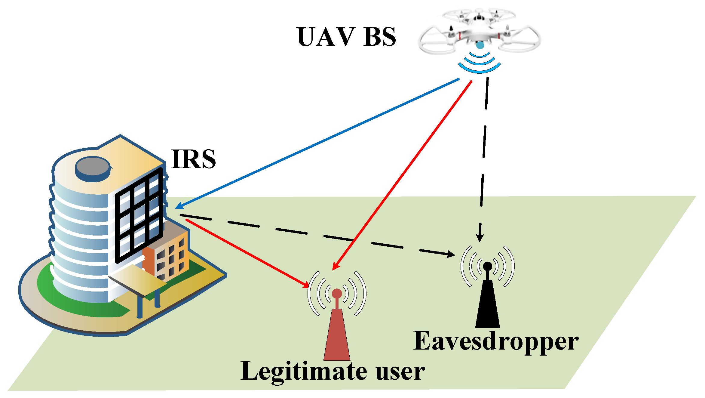
21], we utilize the IRS to enhance the security of the UAV-MIMOME wireless communication system. Specifically, the system is composed of a UAV base station, an IRS, a ground legal receiver, and a ground eavesdropper. Each node is equipped with multiple antennas. The SR of the UAV communication system is maximized by jointly optimizing the TPC matrix and AN matrix, the IRS phase shift matrix, and the UAV placement subjected to transmit power constraint, unit modulus constraint, and maximum moving distance constraint within each iteration interval.
- (2)
Since the optimization problem is non-convex, an AO algorithm is designed to solve it. Specifically, using the weighted minimum mean square error (WMMSE) algorithm to convert the original problem into a tractable equivalent form. For the optimization of the TPC matrix and AN matrix, we introduce auxiliary matrices and solve their expressions by the Lagrange dual method. For the optimization of the IRS phase shift matrix, after the problem is transformed into a constrained quadratically constrained quadratic program (QCQP) problem, three methods of alternating direction method of multipliers (ADMM), majorization-minimization (MM), and Riemannian manifold gradient (RCG) are used to solve it. For the optimization of the UAV placement, existing research based on MISO channels [
24,
25] and traditional convex optimization methods for other parameters [
26,
27,
28]–such as UAV coverage or outage probability–cannot be directly applied to MIMO scenarios with more complex channel models. Therefore, we propose a secrecy rate gradient (SRG) method, which combines the change of the SR with the UAV’s proportional integral (PI) control theory, so that the UAV moves towards the position with greater SR until it reaches the point with the maximum SR.
- (3)
The simulation results verify the advantages of the proposed algorithm compared with the benchmark schemes. It can be seen that the proposed AO algorithm can guide the UAV to move closer to the IRS, which proves that the IRS can effectively improve the security of the UAV communication system. In addition, increasing the transmission power and the number of antennas at legitimate nodes are beneficial to improve the secrecy performance. Moreover, the channel fading coefficients also play an important role in secure UAV-MIMO communications.
The rest parts of this paper are organized as follows. In
Section 2, the system model and the optimization problem are formulated. In
Section 3, we propose an AO algorithm to solve the optimization problem, which alternately solves the three sub-problems of the UAV position, TPC matrix, and AN matrix, and IRS phase shift matrix. In
Section 4, we present the simulation results to verify the effectiveness of the proposed algorithms. We conclude this paper in
Section 5.
Notations: In this paper, matrices and column vectors are denoted by bold uppercase letters and bold lowercase letters, and represent trace and determinant. , , , and denote the transpose, Hermitian, conjugate, and pseudo-inverse operators, respectively. denotes the space of -dimensional complex-valued column vector.
3. Proposed Solution for Joint Optimization
In this section, we propose an AO algorithm to solve the Equation (19). The problem is decomposed into three subproblems; the precoding matrix
and AN matrix
, the IRS phase shift matrix
, and the UAV position
are solved alternately. Since this optimization problem is non-convex and thus difficult to solve, we need to transform it into an easy-to-solve form. Following the work of Hong et al. on IRS aided secure MIMO communication [
31], we convert the objective function of Equation (19) into the following form:
The problem is still an intractable non-convex problem that requires further reformulation. As for
, we transmit the SR maximation problem to another equivalent problem by introducing the weighted minimum mean square error (WMMSE) method [
32]. By introducing the linear decoding matrix
, the MSE matrix of
is
Introducing the slack variable
, and using Lemma 4.1 in [
33],
can be reformulated as
Then the optimal
and
can be expressed as:
Similarly, by introducing the linear decoding matrix
and the slack variable
, we can get the MSE matrix of
, and
can be reformulated as
Then the optimal
and
can be expressed as
As for
, we need to introduce Lemma 1 in [
34] for reformulation,
By introducing the slack variable
, the MSE matrix of
is
Then the optimal
can be expressed as
Therefore, the optimization problem can be expressed as
We can solve this problem by applying the AO method. Firstly, in the following sub-problem (P2), fix the value of to optimize the linear decoding matrices , slack variables , TPC matrix , and AN matrix . Secondly, in the following sub-problem (P3), fix the value of and to optimize the phase shift matrix . And finally, in the following sub-problem (P4), given and , the position of the UAV base station can be solved by the SRG method.
3.1. Optimizing and
Simplifying Formula (32), the sub-optimization problem (P2) can be abbreviated as
The sub-problem is a convex QCQP problem for
and
, but the computational complexity is high if solved directly using CVX. Therefore, the Lagrange dual method is used to solve it. The Lagrangian function of (P2) is
By taking the first-order derivative, the optimal solutions of
and
are obtained as
where
and
.
Further, the eigenvalue decomposition is performed, and the optimal solution are written as
In addition, the optimal dual variable
should satisfy
Define the monotone non-increasing function , we first check whether is satisfied when , if this condition is met, then . Otherwise, the optimal value of the dual variable can be obtained by the bisection search method.
3.2. Optimizing Phase Shift Matrix
In this part, by fixing the value of
and
, the sub-optimization problem (P3) can be abbreviated as
Extracting
and
in the trace operation, the objective function of (P3) can be formulated as
where
is a constant term, which can be ignored in optimization, and
By the Equation (1.9.5) in [
35], remove the trace operation in the third and fourth terms of (40), namely:
where
, similarly, the trace operation in the first and second terms of (40) can be removed as
where
is the conjugate vector of
and
is the vector composed of elements on the diagonal of
. Thus, the phase shift matrix optimization problem can be rewritten as
where
. The right side of the equation is positive semi-definite matrices, so
is also a positive semi-definite matrix. Then, the optimization problem simplifies to
For the form of the optimization problem in (53), we solve it using three low complexity methods: ADMM [
36], MM [
37], and RCG [
38].
3.2.1. Alternating Direction Method of Multipliers
Introducing an auxiliary variable
for
, then the optimization problem can be reformulated as
where
is the penalty parameter. Defining
if
and
, if
,
and
are Lagrange variables corresponding to the real and imaginary parts of
, respectively. Let
, then its Lagrange function can be written as
Therefore, the iterative form of ADMM solution for the dual problem is
For the iteration of
, it is necessary to derive the objective function, and if the derivative is zero, the specific closed expression can be obtained as
For the iteration of
, taking out the terms related to
in
, the optimization problem can be written as
Since the constant term does not affect the solution of the optimization problem, we continue to add the constant term and express the objective function as
If we want to obtain the maximum value of the objective function,
needs to satisfy
Let
, then the projection operation can be expressed as
According to Lemma 3 in [
36], we choose
, where
is the minimum integer which satisfies
.
3.2.2. Majorization-Minimization
The core idea of the MM algorithm is to design a series of approximate optimization functions to control the upper limit of the original function, and to converge to the optimal solution of the original objective by minimizing the sequence.
We use
to represent the upper bound of the objective function. According to Lemma 1 in [
37], we reformulate the problem and rewritten as
Since
,
is constant, after removing the constant term, the sub-problem becomes
Therefore, its optimal solution is given by
where
is the maximum eigenvalue of
.
3.2.3. Riemannian Conjugate Gradient
The RCG method has been widely used in IRS-assisted MISO and MU-MISO communications, so this problem can also be solved using the RCG method. The specific steps are as follows.
Compute Riemannian Gradient: Based on the manifold space constrained by the IRS phase shift matrix, we first calculate the Riemann gradient as the orthogonal projection of the Euclidean gradient on the tangent space,
where
.
Search Direction: The conjugate search direction on the tangent space is
where
is the vector transport function, and it can be expressed as
where
is the Polak-Ribière parameter [
39].
Retraction: Project the tangent vector back to the circular manifold,
where
denotes the Armijo backtracking line step size [
39].
3.3. Optimizing UAV Placement
Aiming at the influence of UAV on the spectral efficiency of centralized radio access network, Roth et al. proposed a UAV location optimization method to maximize the data rate [
40], but this method does not consider the influence of IRS and eavesdroppers. Based on this work, in this part, we propose a secure position searching method for IRS-assisted UAV-MIMO systems–namely the SRG method. The details are as follows.
Fixing other variables except
, the sub-optimization problem of UAV placement (P4) can be expressed as
The SRG method requires the derivative of the SR
with respect to the UAV coordinate, according to [
41]
where the derivative of
with respect to
can be expressed as
Similarly, the derivative of
with respect to
can be expressed as
In the previous research on position optimization and trajectory planning of UAV communication, it was often assumed that the influence of the phase part on the channel was negligible and focused on the influence of distance change on the channel. In this case, we also assume that the phase only has some random and subtle influence on the channel. Therefore, the influence of this part on the position change can be ignored. The derivative part in (73) can be expressed as
We can obtain the gradient of SR as
Next, the state of the UAV is adjusted and controlled by the secrecy rate gradient. When the UAV achieves the maximum SR at a certain point, the position of the UAV should remain unchanged; when the secrecy rate gradient is not zero, the UAV should move along the gradient direction.
In order to meet the above requirements, the static end value of
should match the derivative
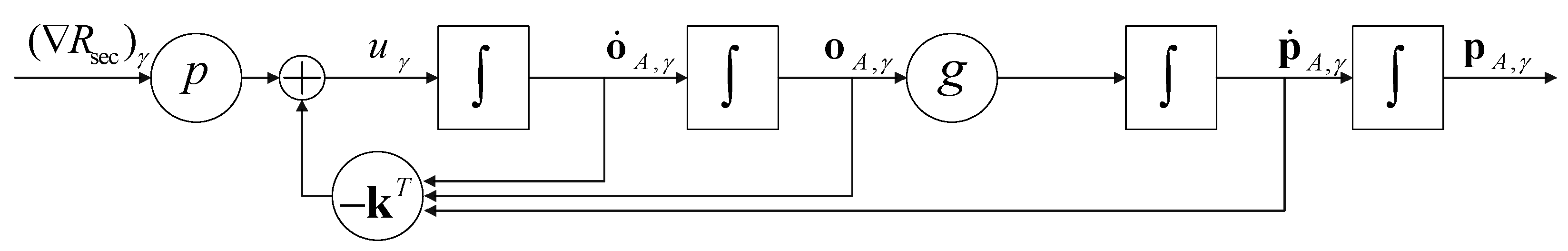
of constant SR. So, with the PI-controller, the input signal is designed as
where
is the controller gain,
is the prefilter coefficient, and the system feedback control flow based on the PI-controller is shown in
Figure 2, where the
represents the superposition of signals, which are calculated by the process indicated by arrows.
In the control system, the controller matrices are determined by a linear quadratic regulator (LQR). Then, the parameters of the whole control system can be deduced as follows:
Therefore, the state equation can be evaluated by
By superimposing the results obtained in the (81) with the state vector of the previous moment, the optimized position of the UAV can be finally obtained.
3.4. Overall Algorithm and Complexity Discussion
With the proposed optimization method of the three sub-problems, the overall algorithm for solving the problem (P1) is summarized in Algorithm 1. Specifically, we iteratively solve three sub-problems–(P2), (P3), and (P4)–using the alternating optimization method. For these three blocks, we fix the other two blocks to optimize a certain block. The solution of other sub-problems obtained in this iteration are used as input to solve the next sub-problem. When the change of SR obtained by two consecutive iterations is less than the convergence accuracy
or the number of iterations exceeds
, the iterative solution can be stopped. The TPC matrix
and AN matrix
are initialized as matrices whose internal elements are all
and
, respectively. And the phase shift matrix
is initialized to the identity matrix.
| Algorithm 1 Iteration Algorithm for Optimizing Problem (P1) |
|
Input: , , , , .
|
|
Output: the TPC matrix and AN matrix, the IRS phase shift matrices, the UAV position, and the SR.
|
| Initialize: the iterative number .
|
| Repeat |
| 1: update , and solve problem (P2) to obtain optimal for given .
|
| 2: Solve problem (P3) to obtain the optimal for given . When choosing to use the ADMM algorithm, iteratively solve by Equations (57)–(59); when choosing to use the MM algorithm, iteratively solve by Equation (67); when choosing to use the RCG algorithm, iteratively solve by Equations (69)–(71) until the SR increment or the maximum iteration number is reached to end the loop of this sub-problem.
|
| 3: Solve problem (P4) to obtain the for given . Using the SRG algorithm, iteratively solves Equation (81) until the SR increment or the maximum iteration number is reached to end the loop of this sub-problem.
|
| 4: Set .
|
| until or . |
For the solution of the IRS phase shift matrix, the iterative process in the ADMM, MM, and RCG sub-algorithms can guarantee the monotonic descent of the sub-problem (P3). Similarly, for the solution of the UAV position, the iterative process in the SRG sub-algorithm also ensures the monotonic decline of the sub-problem (P4). For the solution process of the whole algorithm, the AO algorithm can guarantee the monotonic decrease of the objective function value in each iteration, and the existence of the transmit power constraint ensures the convergence of Algorithm 1.
The complexity of algorithm 1 is analyzed below. In step 1, the computational complexity of
is
, the complexity of binary search to find the optimal
is
, then the computational complexity
of sub-problem (P2) is
. In step 2, the computational complexity
of ADMM, MM, and RCG algorithm are
,
, and
, respectively, where
,
, and
represent the iteration number of three IRS shift optimization sub-algorithms. In step 3, the computational complexity
of the SRG algorithm is
, where
represent the iteration number of the SRG algorithm. Therefore, the complexity of the whole problem can be presented by
4. Simulation Results
In this section, we show the simulation results to verify the effectiveness of Algorithm 1 and the advantage of the proposed secure transmission strategy. The parameter settings we used in the simulation are set as follows unless otherwise specified [
31,
40]. The coordinates of initial UAV point
, IRS, Bob, and Eve are set as
,
,
, and
, respectively. The height of UAV is 60 m and the height of IRS is 25 m. The transmit power limit is
. The antennas number of UAV, Bob, Eve, and IRS are
,
,
, and
, respectively. The number of data streams is set to
. Rician factor is set to
. Path loss exponent
;
and
are set to 2.5;
and
are set to 3.5; and the path loss at the reference distance 1 m is set to −30 dB. The Bob’s noise power and the Eve’s noise power are
and
. The maximum UAV moving distance between two iterations is set to
. The controller gain
. The prefilter coefficient
. The initial UAV states vectors are set to
,
. The convergence accuracy
and the maximum number of iterations
.
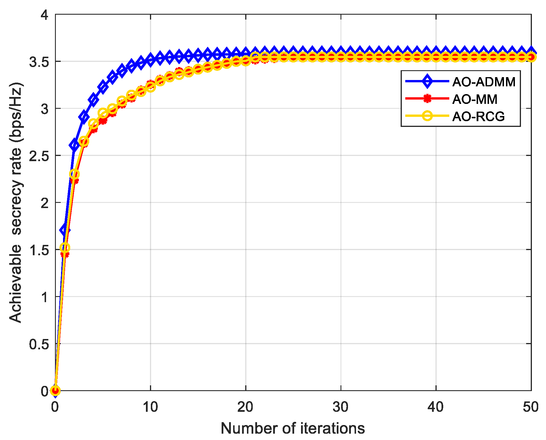
The convergence performance of our proposed Algorithm 1 is described in
Figure 3, where the ADMM, MM, and RCG algorithms are used to optimize the IRS phase shift matrix, respectively. It can be seen from
Figure 3 that for the communication scenario in this paper, with the increase of the number of iterations, the SR gradually increases and converges at about 3.58 after 20~30 iterations, and the convergence speed and secrecy performance of the AO-ADMM algorithm has a little advantage over other two algorithms.
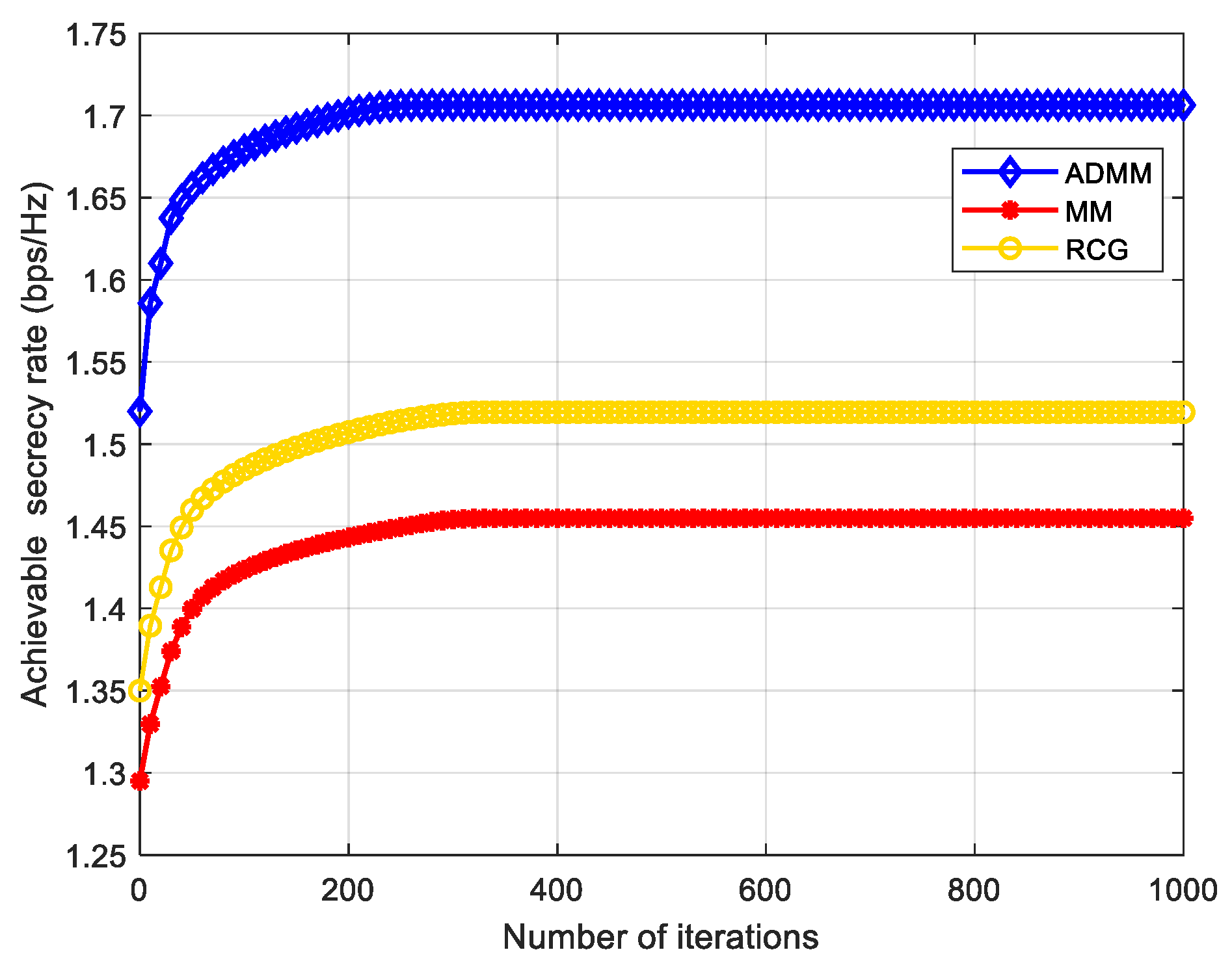
In each iteration of Algorithm 1, ADMM, MM, and RCG are used to solve the problem (P3), the phase shift matrix of IRS.
Figure 4 shows the convergence performance of the three algorithms in the first iteration of our proposed AO algorithm. As can be seen from
Figure 4, the convergence speed of the three algorithms is slightly different, but not by much. Based on the analysis in
Section 3, the computational complexity of MM and RCG algorithms is similar, and the computational complexity of the ADMM algorithm is higher than the other two algorithms. Although the computational complexity of the AO-ADMM algorithm is higher, its convergence performance and SR are slightly better than the other two algorithms. Therefore, we use the AO-ADMM algorithm to compare the performance with other benchmark schemes in the following simulation experiments.
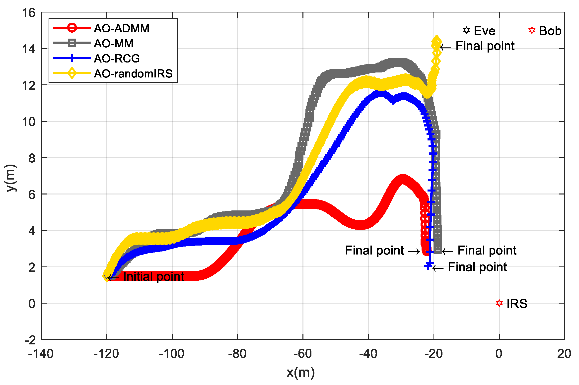
Figure 5 shows the UAV position change process of the AO algorithms based on three different phase shift matrix optimization methods. As a comparison, we also introduce an AO algorithm with a randomly generated IRS phase shift matrix. It can be seen from
Figure 5 that for the case of randomly setting the IRS phase shift, the UAV will move towards the nearby position of the receiver and the eavesdropper. The UAV will not be completely close to Eve and Bob and will finally stop at the
. This is because although the phase shift matrix is not optimal in this case, the IRS can still play a positive role in improving the secrecy performance. For the case of adopting ADMM, MM, and RCG algorithms, the UAV will continue to turn to the nearby position where the IRS is located, and finally stopped at
,
, and
, respectively. This is because the optimized IRS can give a full play to its secrecy ability, and the UAV can obtain a higher SR in the direction close to the IRS, so the UAV will move closer to the IRS. That is to say, the proposed SRG position optimization algorithm and three IRS phase shift matrix optimization methods are important means to effectively improve the secrecy ability.
Next, we consider different benchmark schemes to verify the advantages of our proposed method. The different schemes are shown as follows.
Scheme 1: the TPC matrix, AN matrix, phase shift matrix, and position are optimized via the proposed AO-ADMM algorithm.
Scheme 2: The same as Scheme 1 except that the phase shift matrix is set randomly.
Scheme 3: The same as Scheme 1 except that the TPC matrix is set randomly.
Scheme 4: The same as Scheme 1 except that the AN matrix is set randomly.
Scheme 5: The same as Scheme 1 except that the IRS phase shift matrix is optimized by the one-by-one (OBO) algorithm in paper [
42].
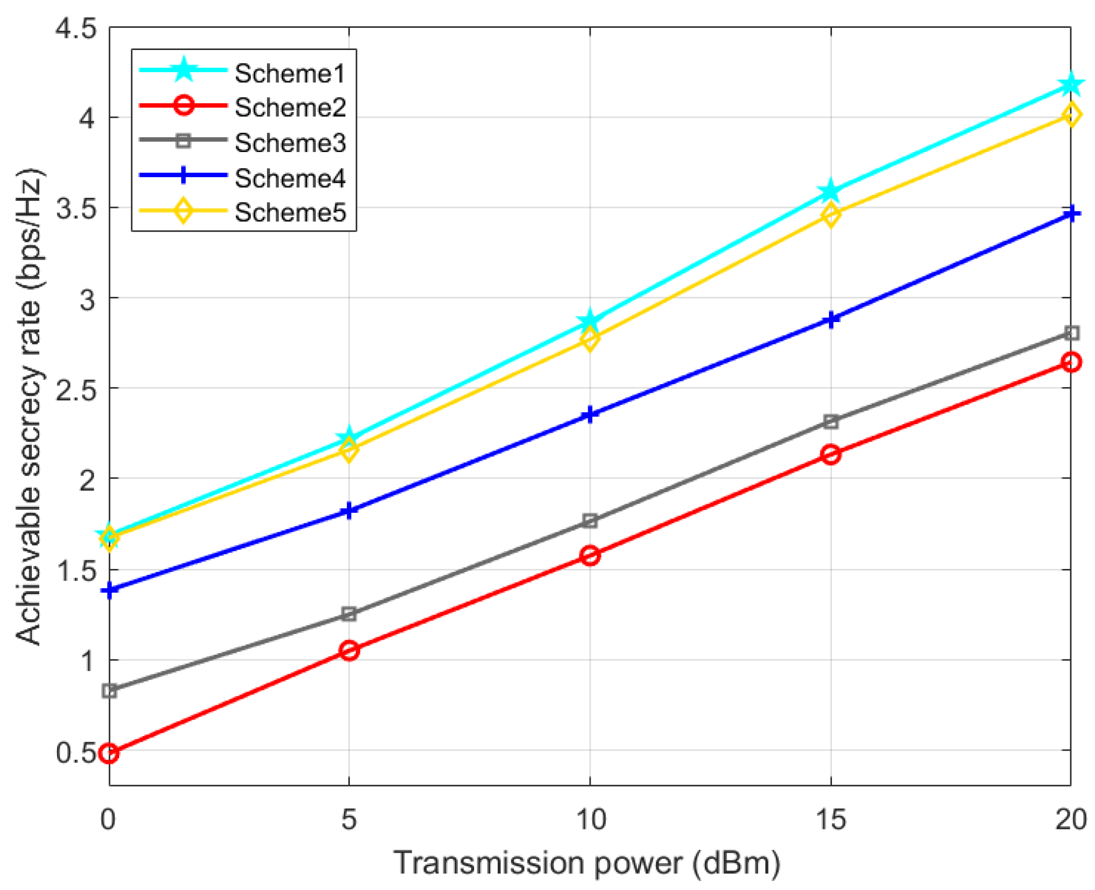
It can be seen from
Figure 6 that as the UAV base station transmission power increases, the achievable SR of all five schemes will increase. Moreover, scheme 1 using the ADMM algorithm is always better than scheme 5 using the OBO algorithm for IRS optimization.
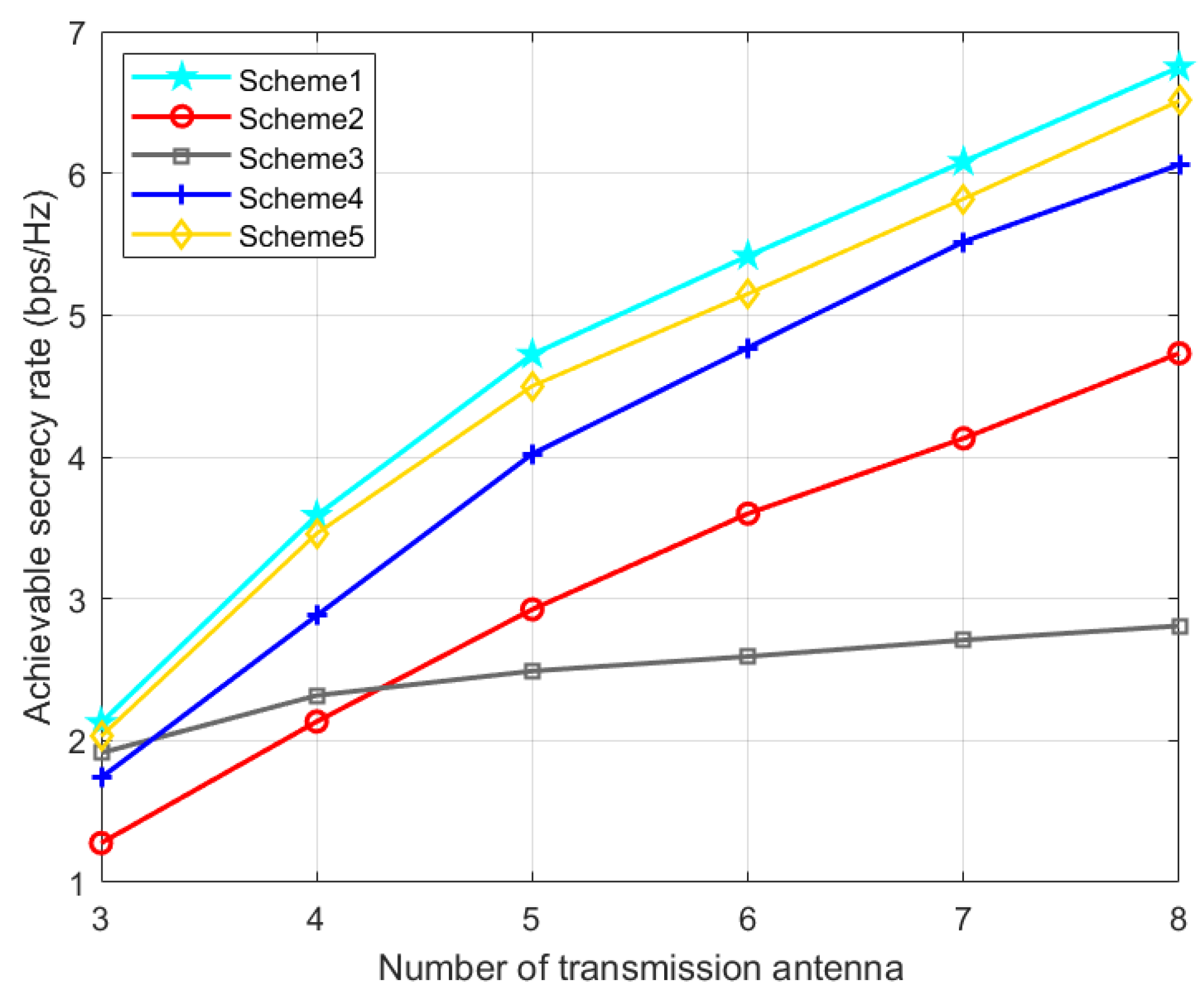
As can be seen from
Figure 7, with the increase in the number of transmission antennas, the achievable SR of all five schemes also increases. In
Figure 7, in the whole region, our proposed scheme 1 has the highest achievable rate. When the number of transmission array is small, compared with scheme 4 and scheme 2, scheme 3 has better confidentiality ability. In addition, when the number of array elements is large, the SR of scheme 4 and scheme 2 is better than that of scheme 3. This is because the number of transmit antennas has a great influence on the performance of TPC matrices.
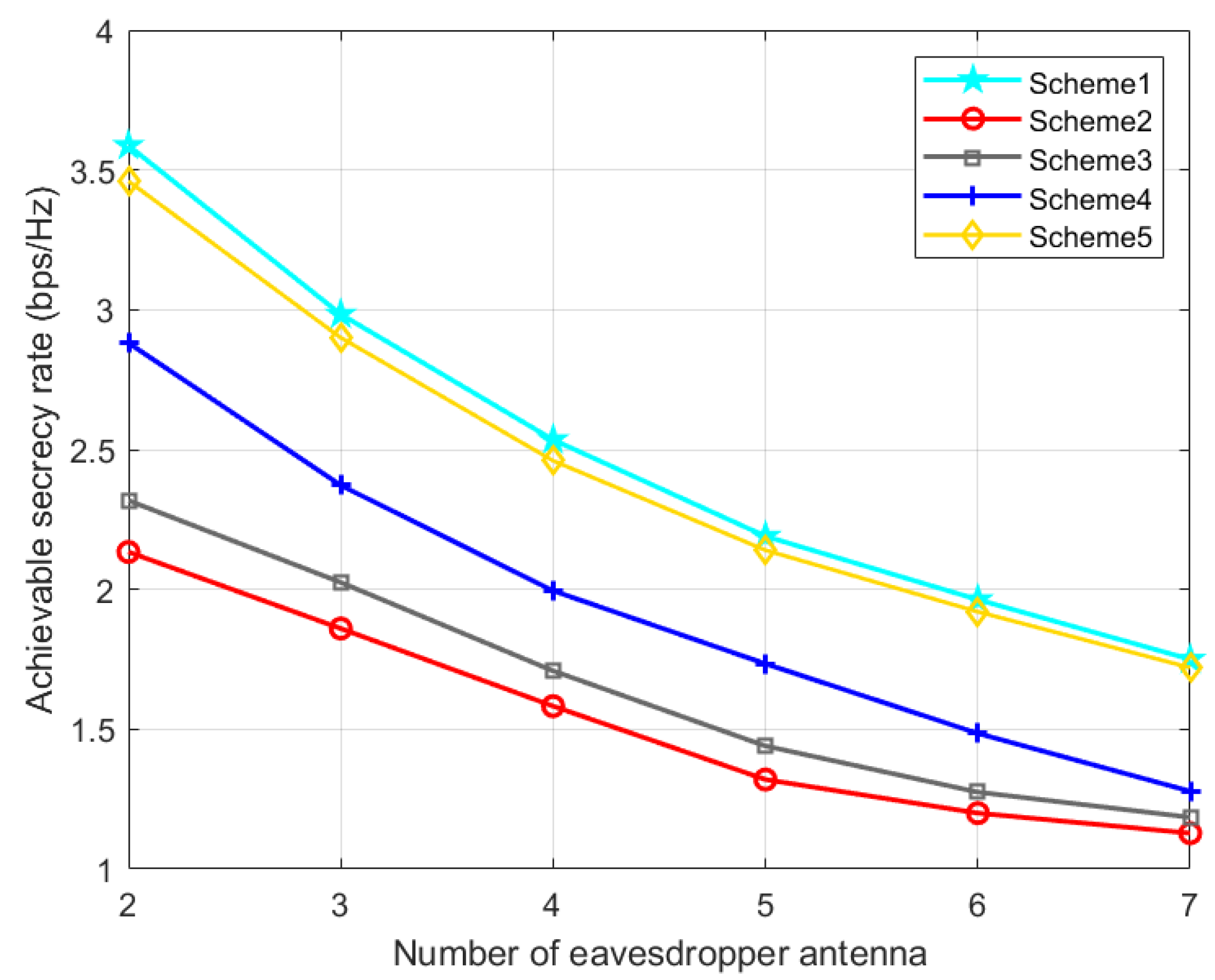
The effect of the number of eavesdropper antenna on the secrecy performance is described in
Figure 8. As the number of eavesdropper antennas increases, the SR of all schemes will decline, and our proposed optimization method is always better than several other schemes.
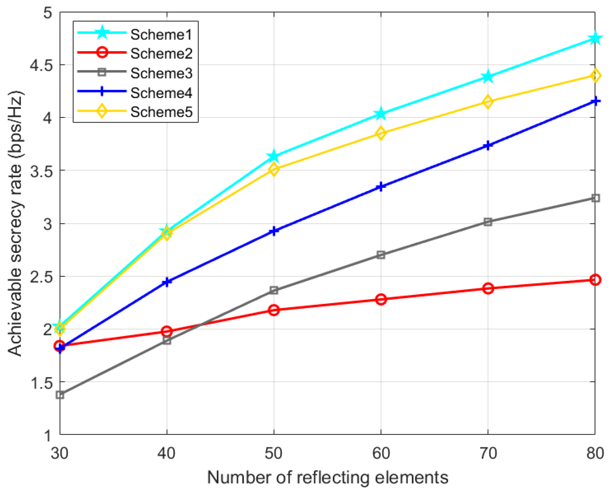
Figure 9 shows the impact of the IRS elements number on the secrecy performance of the UAV system. It is observed from
Figure 9 that with the increase in the number of reflection elements, the SR of all schemes will increase. However, due to the lack of optimization of the phase shift matrix in scheme 2, the SR increases very slowly, which shows the importance of IRS in our proposed joint optimization algorithm. With the preset parameter settings, the SR of our proposed scheme 1 can be about 40.5% higher than that of scheme 2 without IRS. Compared with Scheme 5 using the OBO algorithm, the performance advantage of our proposed Scheme 1 becomes more obvious as the number of IRS elements increases. It proves the effectiveness of Algorithm 1 and the significance of IRS in secure UAV communication.
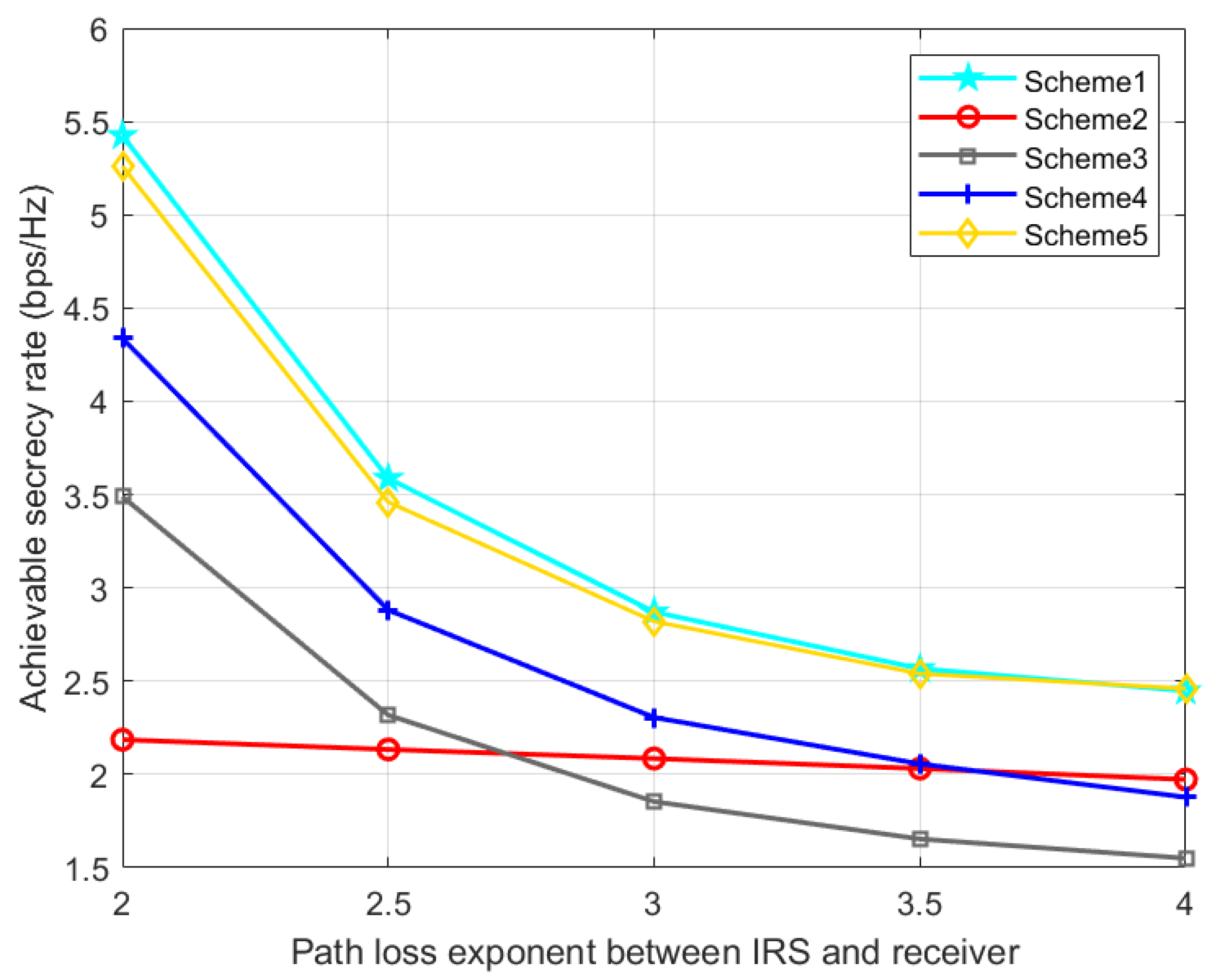
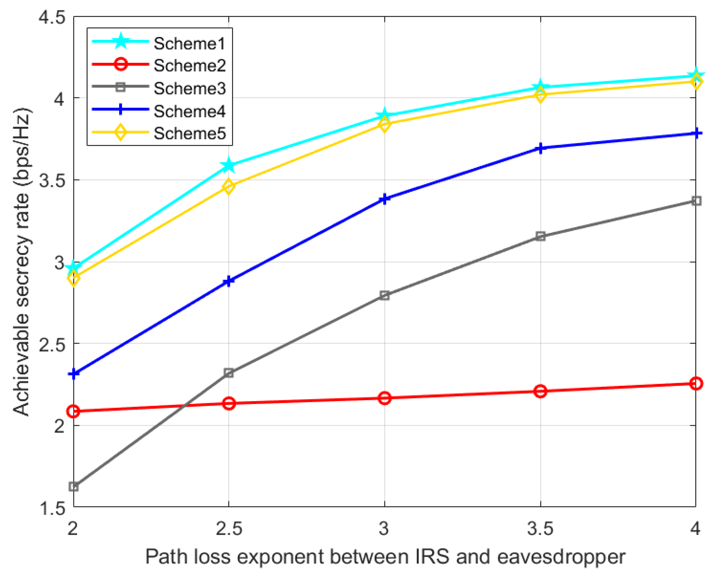
Figure 10 and
Figure 11 show the effect of IRS-Bob and IRS-Eve channel path loss exponents on SR. With the increase of
, the IRS’s signal reflection strength at Bob gradually decreases, resulting in a decrease in the SR. With the increase of
, Eve will receive fewer signals from the IRS, which increases the SR. Therefore, when the quality of the reflected legal channel is good, the IRS can promote the secrecy performance of the communication system, but if the quality of the reflected eavesdropping channel is better than that of the reflected legal channel, the deployment of the IRS may be counterproductive. Our proposed scheme 1 is slightly better than scheme 5, and consistently perform better than the other three benchmark schemes.


