
Cryptanalysis of a New Chaotic Image Encryption Technique Based on Multiple Discrete Dynamical Maps

 ,
,
Abstract
:1. Introduction
2. Overview of Majid’s Encryption Scheme
2.1. Chaotic Maps of the Original Cipher Scheme
2.2. Majid’s Encryption Scheme
- Step 1
- Input a 256 × 256 × 3 plain image, divide it into three channels, and then separate the single-channel image into 32 × 32 blocks.
- Step 2
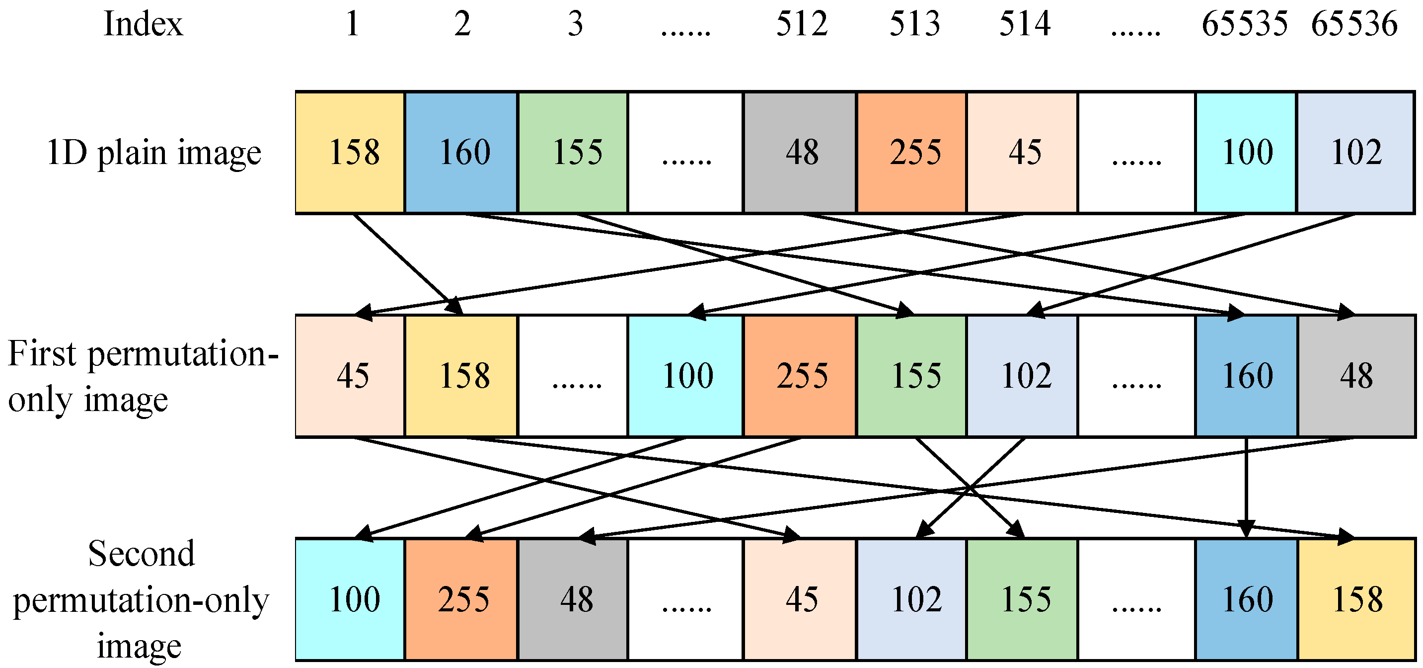
- Generate a chaotic sequence using a two-dimensional Henon chaotic map and perform pixel permutation within blocks of each channel in order.
- Step 3
- Perform random permutation between blocks of each channel orderly.
- Step 4
- Use a circle chaotic map to execute the first diffusion for each channel.
- Step 5
- Use a Duffing chaotic map to execute the second diffusion for each channel.
3. Cryptanalysis
3.1. Preparations
3.2. Elimination of Diffusion Effect
3.2.1. Method 1
- Step 1
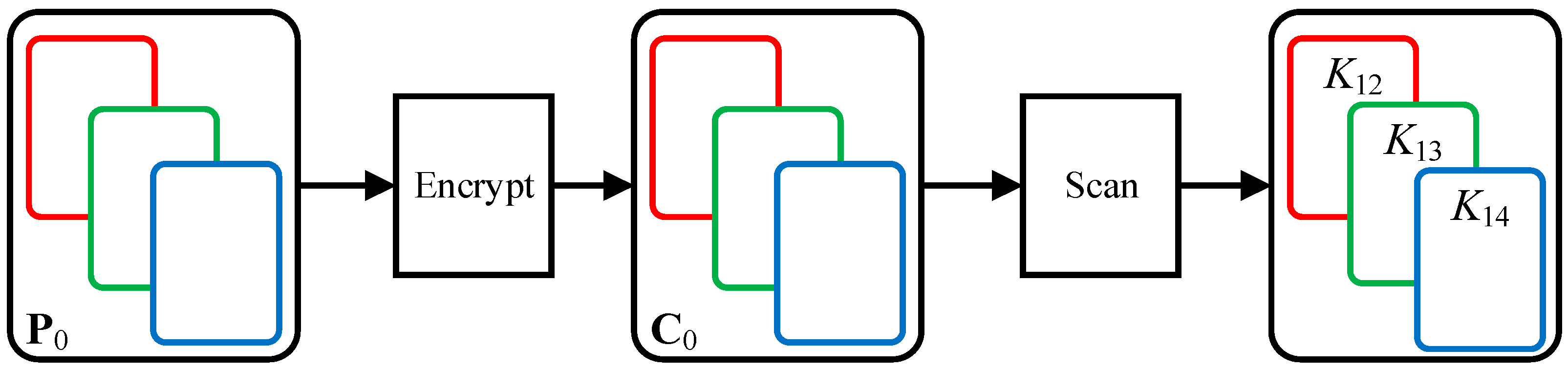
- Construct an all-zero image P0 with 256 × 256 × 3, and the influence of two permutations is eliminated by the all-zero matrix.
- Step 2
- Three equivalent diffusion matrices, K12, K13, and K14, are obtained.
- Step 3
- Then, permutation-only images can be obtained through Equation (32). In the cipher image C, the red channel image CR XOR diffusion matrix K12 is permutation-only image SR, the green channel image CG XOR diffusion matrix K13 is permutation-only image SG, and the red channel image CB XOR diffusion matrix K14 is permutation-only image SB. Three channel images, SR, SG, and SB, are merged to obtain color permutation-only image S.
3.2.2. Method 2
3.3. Obtain Equivalent Permutation Mapping
- Step 1
- Two plain images A1 and A2 were encrypted to obtain two cipher images: CA1 and CA2. The cipher image CA1 is divided into three channel images: Cr1, Cg1, and Cb1. The cipher image CA2 is divided into three channel images: Cr2, Cg2, and Cb2.
- Step 2
- By using method 1 or 2, the permutation-only images Sr1, Sg1, and Sb1 of Cr1, Cg1, and Cb1 are obtained first, and after that, the permutation-only images Sr2, Sg2, and Sb2 of Cr2, Cg2, and Cb2 are obtained.
- Step 3
- Image Sr, Sg and Sb are obtained from Equation (42). Any of the three channel images are stretched row by row to form . Therefore, F′ is an equivalent permutation mapping.
3.4. Summary of the Attack Strategy
3.4.1. Detailed Process of Method 1
- Step 1
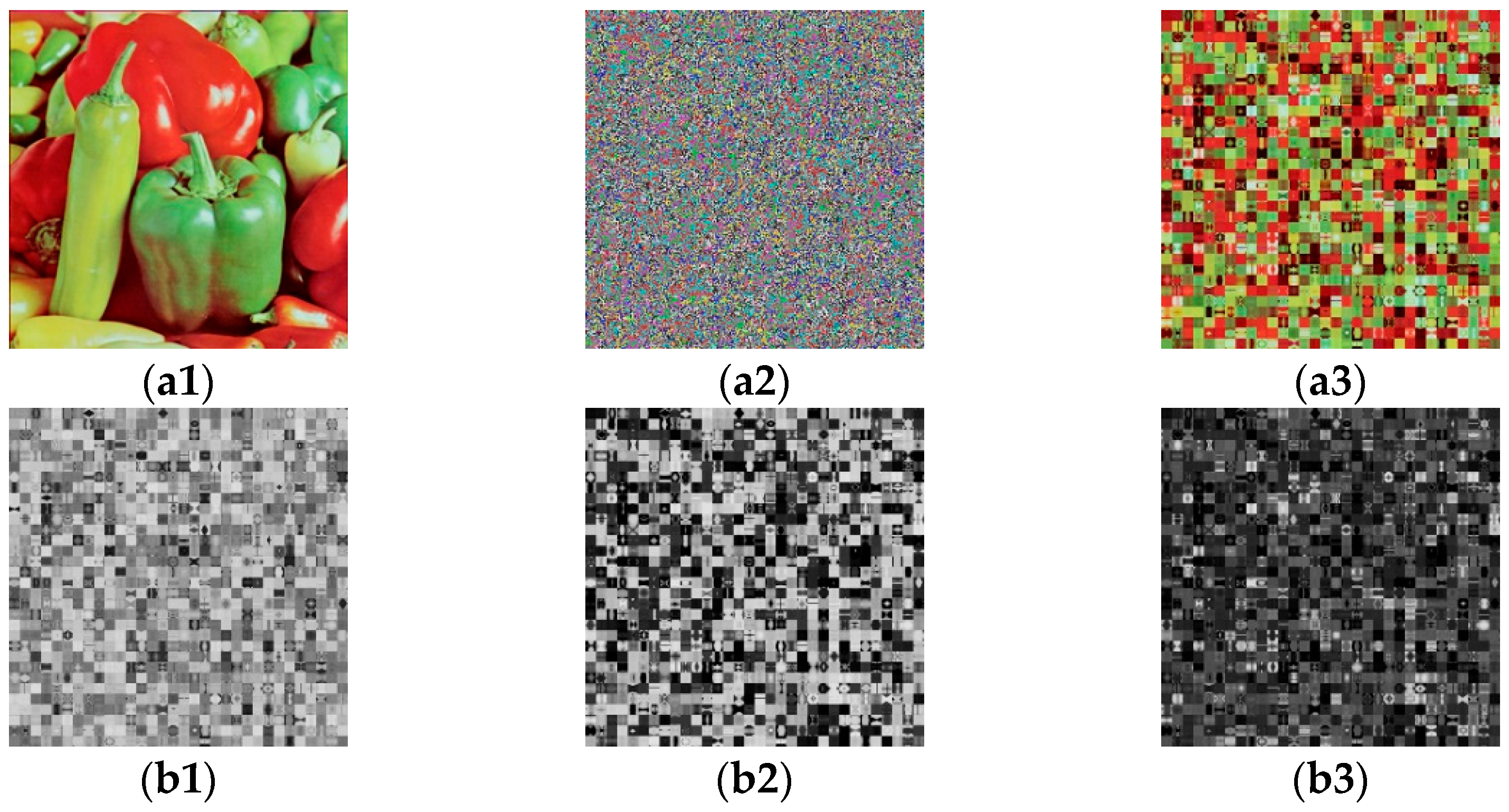
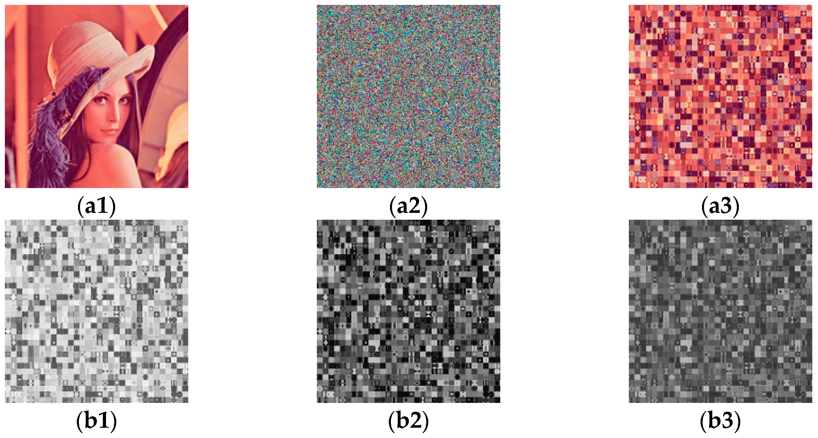
- Based on propositions 1 and 2, the three equivalent diffusion matrices K12, K13 and K14 are obtained from the all-zero image (shown in Figure 2) as described in Section 3.2.1. The diffusion effect is eliminated through the known matrices K12, K13 and K14. Then the permutation-only images of the three channel images CR, CG and CB are obtained through the three matrices as shown in the sub-steps (shown in Figure 3).
- Sub-Steps
- The red channel image CR XORing equivalent diffusion matrix K12 is the permutation-only image SR, the green channel image CG XORing diffusion matrix K13 is the permutation-only image SG, and the red channel image CB XORing diffusion matrix K14 is the permutation-only image SB.
- Step 2
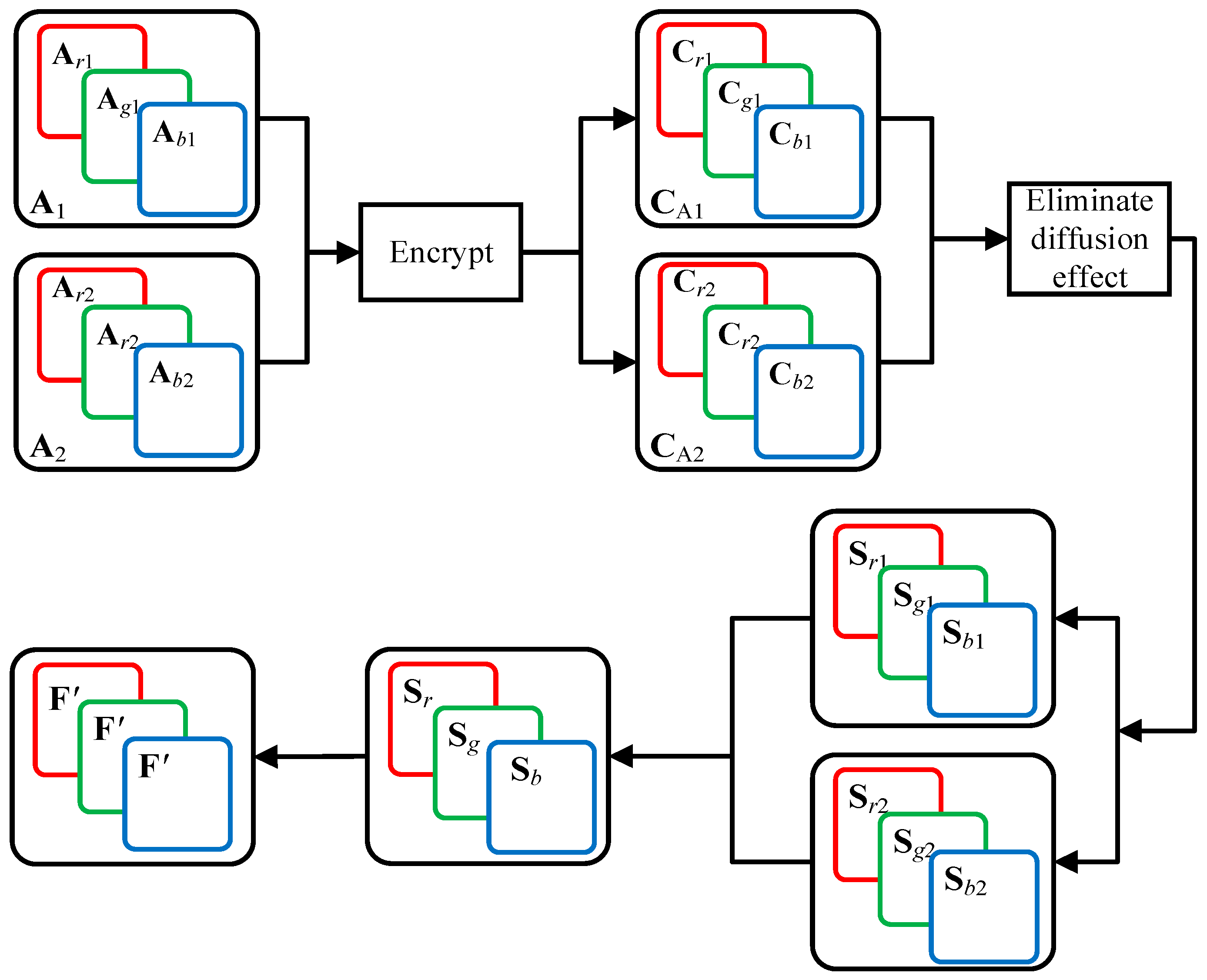
- The equivalent permutation mapping F′ can be obtained from 2 pairs of plain/cipher images (shown in Figure 6) in Section 3.3. The detailed sub-steps are as follows:
- Sub-Step 1
- Two plain images A1 and A2 were encrypted to obtain two cipher images CA1 and CA2. The cipher image CA1 is divided into three channel images Cr1, Cg1 and Cb1. The cipher image CA2 is divided into three channel images Cr2, Cg2 and Cb2.
- Sub-Step 2
- Based on Section 3.2.1, the permutation-only images Sr1, Sg1 and Sb1 of Cr1, Cg1 and Cb1 were obtained, and the permutation-only images Sr2, Sg2 and Sb2 of Cr2, Cg2 and Cb2 were obtained (shown in Figure 7).
- Sub-Step 3
- Sr, Sg and Sb are obtained from Equation (42). All the three channels are stretched row by row to form an equivalent permutation mapping F′.
- Step 3
- Invoke Algorithm 1 to obtain deciphered images PR, PG and PB. Merge the three channel images for obtaining image P.
| Algorithm 1 Obtain the decrypted image P. |
| Decryptimg P = De_Img(Sr, SG, Sb, F′) |
| 1: w = 0; |
| 2: for i from 1 to 256 |
| 3: for j from 1 to 256 |
| 4: [r1, c1] ← find(F′ = w); |
| 5: d_r(i, j) ← Sr(r1, c1); |
| 6: d_g(i, j) ← Sg(r1, c1); |
| 7: d_b(i, j) ← Sb(r1, c1); |
| 8: w + 1 ← w; |
| 9: end |
| 10: end |
| 11: P ← d_r, d_g, d_b //Merge three channels |
3.4.2. Detailed Process of Method 2
- Step 1
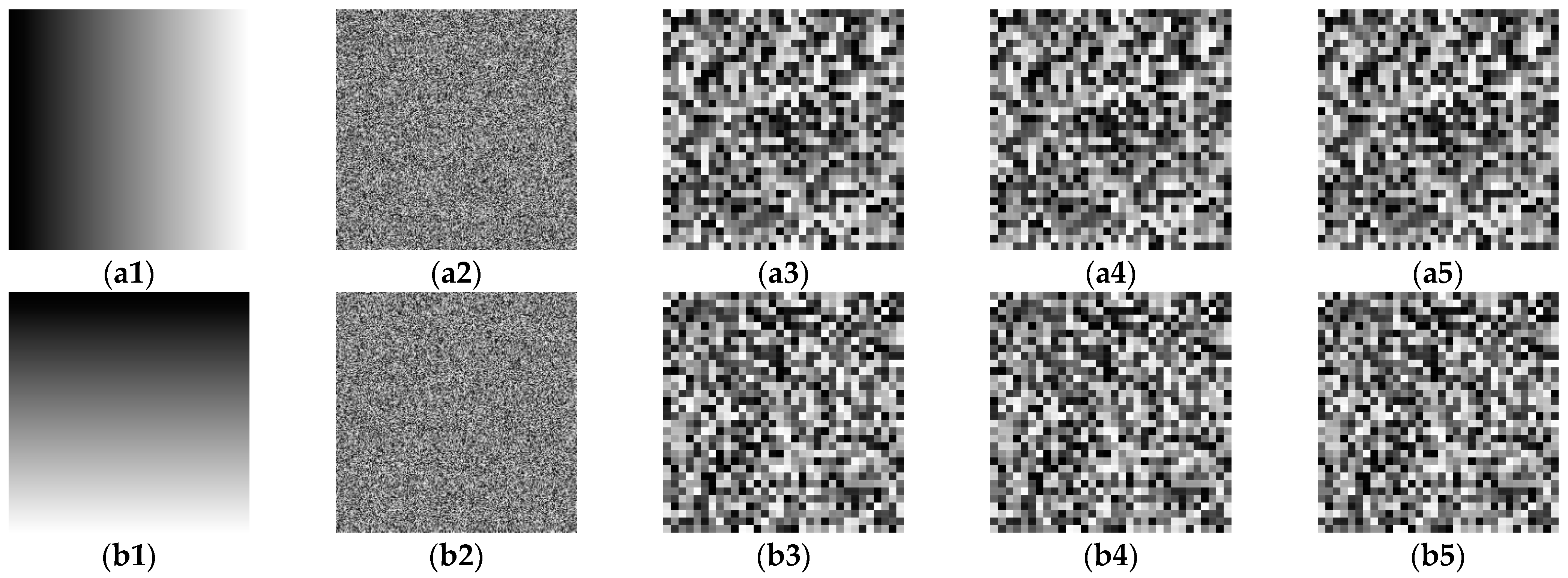
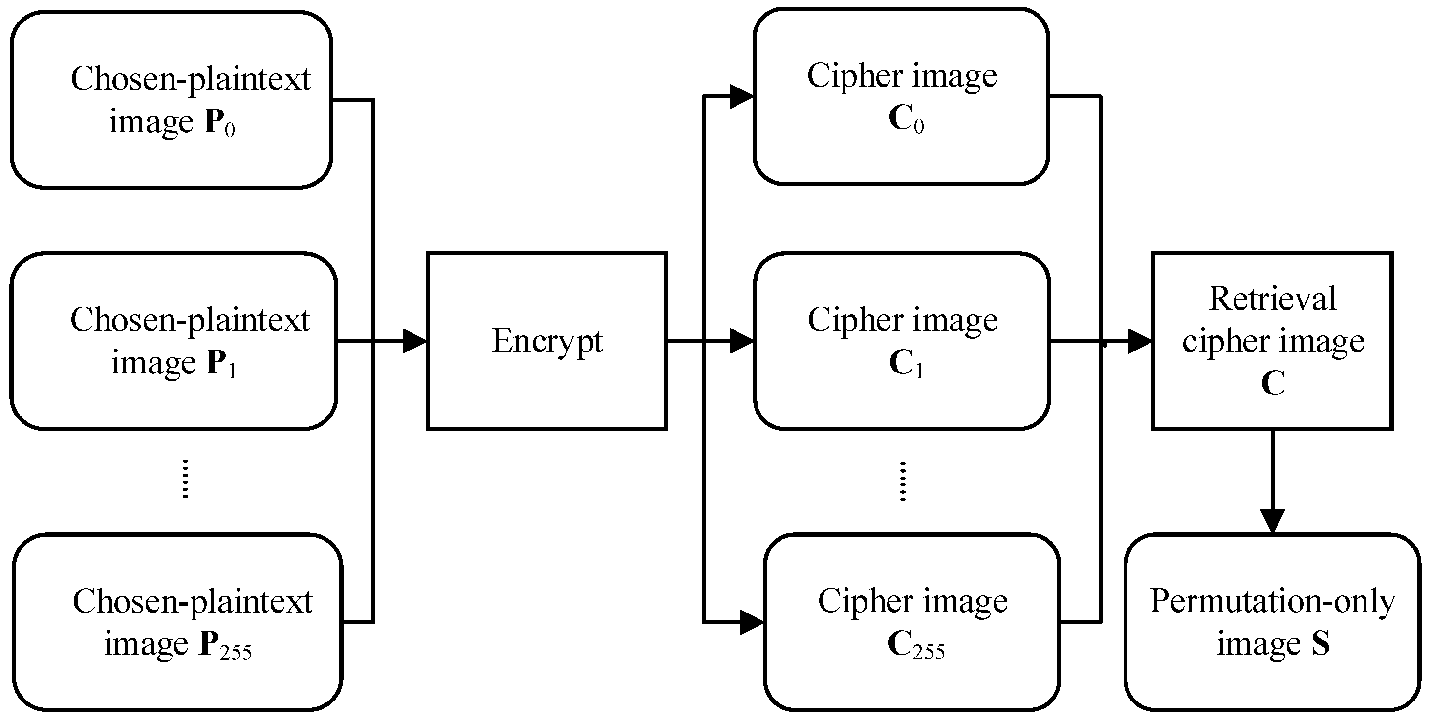
- Based on proposition 3, one can construct 256 different plain images and encrypt them to obtain 256 different cipher images (shown in Figure 4) in Section 3.2.2. For the three channel images CR, CG and CB of the given cipher image C. Equations (34) and (35) are used to eliminate the diffusion effect. The permutation-only images SR, SG and SB of the three channels are retrieved (shown in Figure 5).
- Step 2
- The equivalent permutation mapping F′ can be obtained from 2 pairs of plain/cipher images (shown in Figure 6) as described in Section 3.3. The detailed sub-steps are the same as the three sub-steps of step 2 in Section 3.4.1.
- Step 3
- Invoke Algorithm 1 to obtain deciphered images PR, PG and PB. Then, image P is obtained by merging the three channel images.
3.5. Simulation Experiment
3.5.1. Computational Complexity Analysis
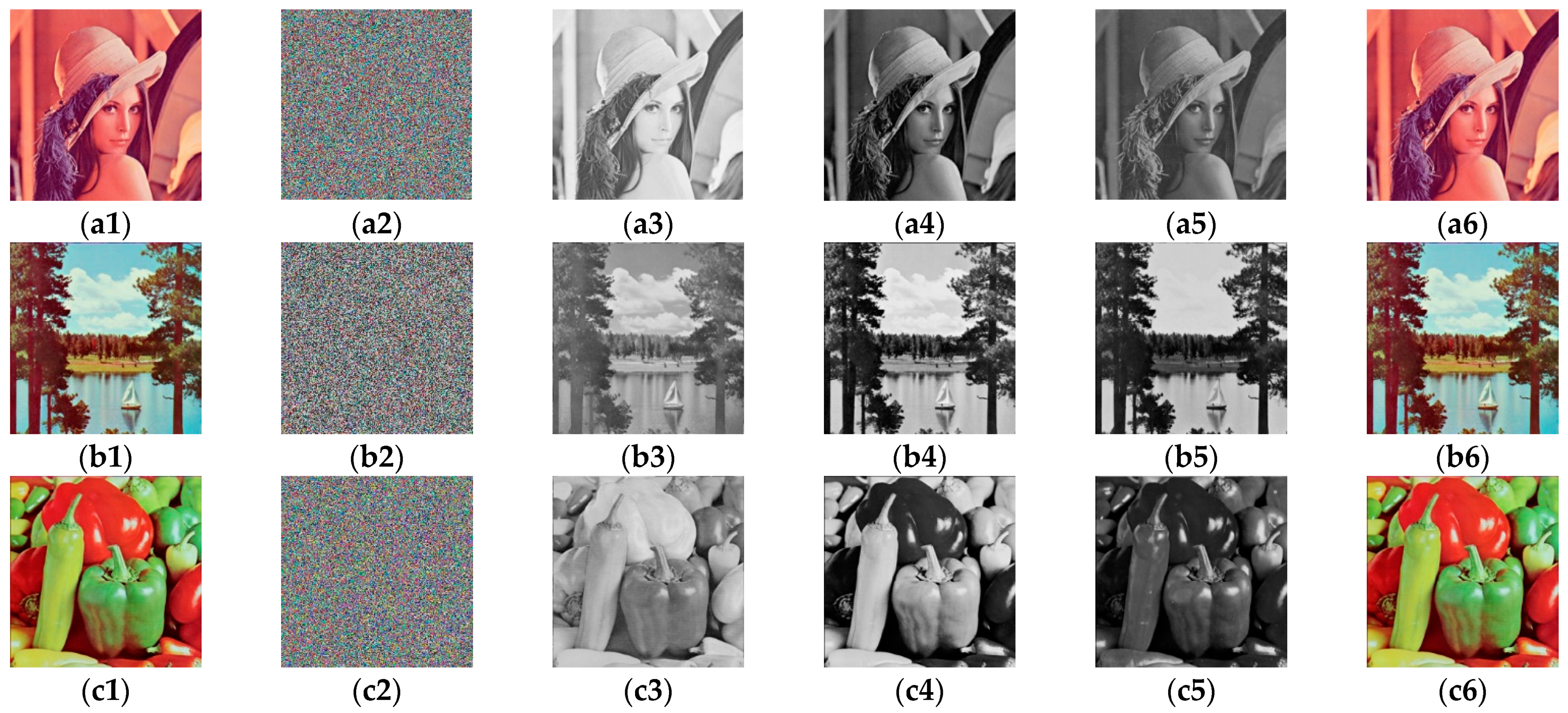
3.5.2. Experimental Results
4. Conclusions
Author Contributions
Funding
Institutional Review Board Statement
Informed Consent Statement
Data Availability Statement
Conflicts of Interest
References
- Zhang, E.; Li, M.; Yiu, S.; Du, J.; Zhu, J.; Jin, G. Fair hierarchical secret sharing scheme based on smart contract. Inf. Sci. 2021, 546, 166–176. [Google Scholar] [CrossRef]
- Zhang, E.; Li, H.; Huang, Y.; Hong, S.; Zhao, L.; Ji, C. Practical multi-party private collaborative k-means clustering. Neurocomputing 2022, 467, 256–265. [Google Scholar] [CrossRef]
- Daudigny, R.; Ledig, H.; Muller, F.; Valette, F. SCARE of the DES—(Side channel analysis for reverse engineering of the data encryption standard). Appl. Cryptogr. Netw. Secur. Proc. 2005, 3531, 393–406. [Google Scholar]
- Ap, W.S.; Phan, R.C.W.; Goi, B.M. Cryptanalysis of a highdefnition image encryption based on AES modifcation. Wirel. Pers. Commun. 2016, 88, 685–699. [Google Scholar]
- Hua, Z.Y.; Zhou, Y.C.; Pun, C.M.; Chen, C.L.P. 2D Sine Logistic modulation map for image encryption. Inf. Sci. 2015, 297, 80–94. [Google Scholar] [CrossRef]
- Ua, Z.Y.; Zhou, Y.C. Image encryption using 2D logisticadjusted-sine map. Inf. Sci. 2016, 339, 237–253. [Google Scholar]
- Enayatifar, R.; Abdullah, A.H.; Isnin, I.F.; Altameem, A.; Lee, M. Image encryption using a synchronous permutation-difusion technique. Opt. Lasers Eng. 2017, 90, 146–154. [Google Scholar] [CrossRef]
- Irfan, Y.; Majid, K. A New Efficient Digital Image Encryption Based on Inverse Left Almost Semi Group and Lorenz Chaotic System. Entropy 2018, 20, 913. [Google Scholar]
- Diab, H.; El-Semary, A.M. Secure image cryptosystem with unique key streams via hyper-chaotic system. Signal Process. 2018, 142, 53–68. [Google Scholar] [CrossRef]
- Chen, J.X.; Zhu, Z.L.; Zhang, L.B.; Zhang, Y.S.; Yang, B.Q. Exploiting self-adaptive permutation-difusion and DNA random encoding for secure and efcient image encryption. Signal Process. 2018, 142, 340–353. [Google Scholar] [CrossRef]
- Zou, C.; Wang, X.; Li, H. Image encryption algorithm with matrix semi-tensor product. Nonlinear Dyn. 2021, 105, 859–876. [Google Scholar] [CrossRef]
- Xingyuan, W.; Maochang, Z. An image encryption algorithm based on hyperchaotic system and DNA coding. Opt. Laser Technol. 2021, 143, 107316. [Google Scholar]
- Fridrich, J. Image encryption based on chaotic maps. IEEE Int. Conf. Syst. 1997, 2, 1105–1110. [Google Scholar]
- Zhou, Y.C.; Bao, L.; Chen, C.L.P. A new 1D chaotic system for image encryption. Signal Process. 2014, 97, 172–182. [Google Scholar] [CrossRef]
- Pak, C.; Huang, L. A new color image encryption using combination of the 1D chaotic map. Signal Process. 2017, 138, 129–137. [Google Scholar] [CrossRef]
- Hua, Z.; Zhou, Y. Design of image cipher using block-based scrambling and image filtering. Inf. Sci. 2017, 396, 97–113. [Google Scholar] [CrossRef]
- Niyat Yaghouti, A.; Moattar, M.H.; Torshiz Niazi, M. Color image encryption based on hybrid hyper-chaotic system and cellular automata. Opt. Lasers Eng. 2017, 90, 225–237. [Google Scholar] [CrossRef]
- Wu, J.; Liao, X.; Yang, B. Image encryption using 2D Hénon-Sine map and DNA approach. Signal Process. 2018, 153, 11–23. [Google Scholar] [CrossRef]
- Li, M.; Wang, P.C.; Liu, Y.F.; Fan, H.J. Cryptanalysis of a novel bit-level color image encryption using improved 1D chaotic map. IEEE Access. 2019, 7, 145798–145806. [Google Scholar] [CrossRef]
- Wang, H.; Xiao, D.; Chen, X.; Huang, H. Cryptanalysis and enhancements of image encryption using combination of the 1D chaotic map. Signal Process. 2018, 144, 444–452. [Google Scholar] [CrossRef]
- Feng, Y.; Xinhui, G.; Hanpeng, L.; Shihong, W. Differential cryptanalysis of image cipher using block-based scrambling and image filtering. Inf. Sci. 2021, 554, 145–156. [Google Scholar]
- Li, M.; Lu, D.D.; Wen, W.; Ren, H.; Zhang, Y. Cryptanalyzing a color image encryption scheme based on hybrid hyper-chaotic system and cellular automata. IEEE Access 2018, 6, 47102–47111. [Google Scholar] [CrossRef]
- Chen, J.; Chen, L.; Zhou, Y. Cryptanalysis of a DNA-based image encryption scheme. Inf. Sci. 2020, 520, 130–141. [Google Scholar] [CrossRef]
- Hu, G.Q.; Xiao, D.; Wang, Y.; Li, X. Cryptanalysis of a chaotic image cipher using Latin square-based confusion and diffusion. Nonlinear Dyn. 2017, 88, 1305–1316. [Google Scholar] [CrossRef]
- Li, M.; Lu, D.D.; Xiang, Y.; Zhang, Y.; Ren, H. Cryptanalysis and improvement of a chaotic image cipher using two-round permutation and diffusion. Nonlinear Dyn. 2019, 96, 31–47. [Google Scholar] [CrossRef]
- Hsiao, H.I.; Lee, J. Color image encryption using chaotic nonlinear adaptive filter. Signal Process. 2015, 117, 281–309. [Google Scholar] [CrossRef]
- Fan, H.; Li, M.; Liu, D.; Zhang, E. Cryptanalysis of a colour image encryption using chaotic APFM nonlinear adaptive filter. Signal Process. 2018, 143, 28–41. [Google Scholar] [CrossRef]
- Sheela, S.J.; Suresh, K.V.; Tandur, D. Image encryption based on modified Henon map using hybrid chaotic shift transform. Multimed. Tools Appl. 2018, 77, 25223–25251. [Google Scholar] [CrossRef]
- Zhou, K.; Xu, M.; Luo, J.; Fan, H.; Li, M. Cryptanalyzing an image encryption based on a modified Henon map using hybrid chaotic shift transform. Digit. Signal Process. 2019, 93, 115–127. [Google Scholar] [CrossRef]
- Mondal, B.; Behera, P.K.; Gangopadhyay, S. A secure image encryption scheme based on a novel 2D sine-cosine cross-chaotic (SC3) map. J. Real-Time Image Process. 2020, 18, 1–18. [Google Scholar] [CrossRef]
- Li, M.; Wang, P.; Yue, Y.; Liu, Y. Cryptanalysis of a secure image encryption scheme based on a novel 2D sine–cosine cross-chaotic map. J. Real-Time Image Process. 2021. (prepublish). [Google Scholar] [CrossRef]
- Khan, M.; Masood, F. A novel chaotic image encryption technique based on multiple discrete dynamical maps. Multimed. Tools Appl. 2019, 78, 26203–26222. [Google Scholar] [CrossRef]
- Arroyo, D.; Diaz, J.; Rodriguez, F.B. Cryptanalysis of a one round chaos-based substitution permutation network. Signal Process. 2012, 93, 1358–1364. [Google Scholar] [CrossRef] [Green Version]
- Zhang, L.Y.; Liu, Y.; Pareschi, F.; Zhang, Y.; Wong, K.W.; Rovatti, R.; Setti, G. On the security of a class of diffusion mechanisms for image encryption. IEEE Trans. Cybern. 2017, 99, 1163–1175. [Google Scholar] [CrossRef] [PubMed]
- Jolfaei, A.; Wu, X.; Muthukkumarasamy, V. On the security of permutation-only image encryption schemes. IEEE Trans. Inf. Forensics Secur. 2016, 11, 235–246. [Google Scholar] [CrossRef] [Green Version]


| Image | Image Size | Encryption | Deciphering | |
|---|---|---|---|---|
| Method 1 | Method 2 | |||
| Lena | 256 × 256 × 3 | 1.191755 | 9.057486 | 235.661488 |
| Pepper | 256 × 256 × 3 | 1.083255 | 8.445166 | 233.262743 |
| Sailboat | 256 × 256 × 3 | 1.058173 | 8.273460 | 233.330141 |
Publisher’s Note: MDPI stays neutral with regard to jurisdictional claims in published maps and institutional affiliations. |
© 2021 by the authors. Licensee MDPI, Basel, Switzerland. This article is an open access article distributed under the terms and conditions of the Creative Commons Attribution (CC BY) license (https://creativecommons.org/licenses/by/4.0/).
Share and Cite
Fan, H.; Zhang, C.; Lu, H.; Li, M.; Liu, Y. Cryptanalysis of a New Chaotic Image Encryption Technique Based on Multiple Discrete Dynamical Maps. Entropy 2021, 23, 1581. https://doi.org/10.3390/e23121581
Fan H, Zhang C, Lu H, Li M, Liu Y. Cryptanalysis of a New Chaotic Image Encryption Technique Based on Multiple Discrete Dynamical Maps. Entropy. 2021; 23(12):1581. https://doi.org/10.3390/e23121581
Chicago/Turabian StyleFan, Haiju, Chenjiu Zhang, Heng Lu, Ming Li, and Yanfang Liu. 2021. "Cryptanalysis of a New Chaotic Image Encryption Technique Based on Multiple Discrete Dynamical Maps" Entropy 23, no. 12: 1581. https://doi.org/10.3390/e23121581
APA StyleFan, H., Zhang, C., Lu, H., Li, M., & Liu, Y. (2021). Cryptanalysis of a New Chaotic Image Encryption Technique Based on Multiple Discrete Dynamical Maps. Entropy, 23(12), 1581. https://doi.org/10.3390/e23121581