Article

Thermodynamic Analysis of a Hybrid Power System Combining Kalina Cycle with Liquid Air Energy Storage

1
State Key Laboratory of Control and Simulation of Power System and Generation Equipment, Department of Electrical Engineering, Tsinghua University, Beijing 100084, China
2
School of QiDi (TUS) Renewable Energy, Qinghai University, Xining 810016, China
3
China Salt Jintan Chemical Co., Ltd., Changzhou 213200, China
*
Authors to whom correspondence should be addressed.
Entropy 2019, 21(3), 220; https://doi.org/10.3390/e21030220
Submission received: 15 January 2019 / Revised: 19 February 2019 / Accepted: 21 February 2019 / Published: 26 February 2019
(This article belongs to the Special Issue Thermodynamic Approaches in Modern Engineering Systems)

Abstract

:
Liquid air energy storage (LAES) is a promising energy storage technology in consuming renewable energy and electricity grid management. In the baseline LAES (B-LAES), the compression heat is only utilized in heating the inlet air of turbines, and a large amount of compression heat is surplus, leading to a low round-trip efficiency (RTE). In this paper, an integrated energy system based on LAES and the Kalina cycle (KC), called KC-LAES, is proposed and analyzed. In the proposed system, the surplus compression heat is utilized to drive a KC system to generate additional electricity in the discharging process. An energetic model is developed to evaluate the performance of the KC and the KC-LAES. In the analysis of the KC subsystem, the calculation results show that the evaporating temperature has less influence on the performance of the KC-LAES system than the B-LAES system, and the optimal working fluid concentration and operating pressure are 85% and 12 MPa, respectively. For the KC-LAES, the calculation results indicate that the introduction of the KC notably improves the compression heat utilization ratio of the LAES, thereby improving the RTE. With a liquefaction pressure value of eight MPa and an expansion pressure value of four MPa, the RTE of the KC-LAES is 57.18%, while that of the B-LAES is 52.16%.

1. Introduction

Large-scale energy storage is an effective solution for improving and expanding renewable energy systems. It can also be used for the storage of electrical energy and for grid load shifting. Currently, pumped hydro energy storage (PHES) and compressed air energy storage (CAES) are the major large-scale energy storage technologies. PHES is well-developed and efficient, but it is restricted by geological characteristics. Small-scale CAES systems usually use a high-pressure container as the air storage tank [1], which increases the investment cost and limits the install capacity. In large-scale CAES systems, salt caverns and underground mines can be used for storing the high-pressure air [2], but here again, the locations of the plants are restricted by geological characteristics.
Apart from PHES and CAES, another promising solution for large-scale energy storage is liquid air energy storage (LAES), which has the notable advantages of high energy-storage density and no geological constraints. The concept of storing energy in liquid air was first proposed by Smith in 1977 [3], and Highview Power Storage Ltd. designed and established the world’s first LAES pilot plant (350 kW/2.5 MWh) [4]. Since then, many researchers have studied the performance of standalone LAES and integrated LAES systems with various configurations. Ameel et al. [5] investigated a thermodynamic cycle for energy storage using liquid air, and a maximum round-trip efficiency (RTE) of 43.3% was attained. Sciacovelli et al. [6] studied a standalone LAES system with packed bed cold energy storage. The dynamic characteristics of the system were analyzed, and an RTE of 50% was obtained. Xue et al. [7] presented a thermodynamic analysis of a standalone LAES system, and the influence of key parameters was discussed. Guizzi et al. [8] investigated an LAES system with cryogenic liquid cold energy storage and assessed its efficiency. An RTE in the range of 54–55% could be obtained with reasonable and conservative design parameters. Howe et al. [9] presented an energy and exergy analysis for a combined building-scale LAES system. Their analytical approach can be applied to other LAES configurations to identify optimal operating parameters. Tafone et al. [10] studied an LAES system as a cooling application in hot climates, and an RTE of 45% was obtained.
In the study of integrated LAES systems, Li et al. [11] proposed a hybrid system, integrating LAES with nuclear power plants and obtaining a high RTE of 70%. Zhang et al. [12] introduced the cold energy of liquefied natural gas (LNG) into the liquefaction process of LAES, and a higher electrical energy storage efficiency was obtained. Antonelli et al. [13] analyzed the potential and challenges of hybrid power plants based on LAES; the performance of possible configurations was analyzed and compared. Al-Zareer et al. [14] studied hybrid LAES systems for district heating and cooling. Brayton, Rankine, and absorption cooling cycles were introduced into the system, and an RTE of about 70% was obtained.
In baseline LAES (B-LAES), the compression heat is surplus because of the low liquefaction ratio. Therefore, the effective utilization of compression heat has a significant influence on the RTE of an LAES system. She et al. [15] introduced an organic Rankine cycle (ORC) system driven by the surplus compression heat into an LAES system to improve its RTE. In a subsequent study, Peng et al. [16] compared two configurations of ORC systems with different cold sources: ambient and a low-temperature cold source obtained through an absorption refrigeration cycle. The results indicated that the introduction of an ORC can effectively improve the performance of the system, and the LAES combined with the ambient ORC system had the better performance. In order to further improve the RTE of LAES, Tafone et al. [17,18] studied and compared different integrated LAES systems consisting of an ORC and an absorption chiller. The results showed that such integrated energy systems can significantly improve efficiency and reduce the payback period.
Apart from the ORC system, another representative technology for utilizing waste heat to generate electricity is the Kalina cycle (KC). The KC used ammonia–water as the working fluid to realize a good temperature match between the heat source and working fluid due to the variable boiling temperature of ammonia–water [19,20]. Numerous investigations have been carried out to study the performance of the KC from the perspective of the first and second law of thermodynamics [21,22]. Moreover, the KC also has been considered as both the bottom and topping cycle in the integrated systems. For example, Zhao et al. [23] presented a thermodynamic analysis of an integrated energy system based on CAES and KC. In another study, Li et al. [24] compared the performance of KC and ORC in recovering the residual heat of CAES. In this paper, a novel integrated energy system based on LAES and KC (KC-LAES) is proposed and studied. In the discharging process of the proposed system, the stored compression heat is first used to heat the inlet air to the air turbines; then, the surplus portion is used to drive the KC subsystem to generate additional electricity. A mathematical model is developed to analyze the performance of the KC and the integrated energy system. In the analysis of the KC, the influence of the basic concentration of ammonia–water, the evaporating temperature, and the operating pressure is discussed. In the analysis of the KC-LAES, the influence of the liquefaction and expansion pressure is studied. Finally, the calculation results of the KC-LAES with typical operating parameters are presented and discussed.

2. System Description

Figure 1 shows the schematic of the proposed KC-LAES. In order to clearly describe and analyze the system, all the streams have been numbered. The bottom part of 
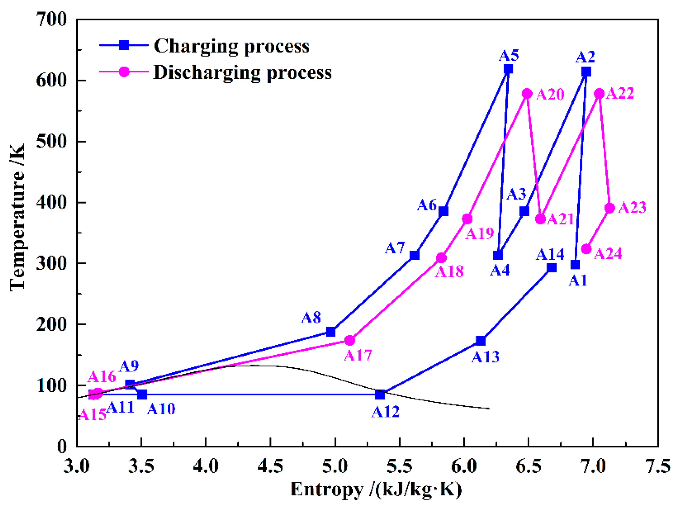
Figure 1 is a typical B-LAES with cryogenic liquid cold energy storage, and Figure 2 shows its T–s diagram. In the charging process, the air is compressed to a high-pressure state (A7), and then cooled to a liquid state (A9). The high and low temperature compression heat generated in the compression process is stored in thermal oil and water, respectively. The cold energy utilized in cooling the compressed air is harvested in the discharging process. Then, a vapor–liquid mixture (A10) is obtained through an expansion process in the throttle valve (TV). After separation, the liquid air (A11) is stored in the liquid air tank (LAT), and the gaseous air (A12) flows black to cool the compressed air. In the discharging process, the liquid air is first pumped to a high-pressure state (A16), and then flows through a two-stage heat exchanger to be gasified. During the gasification process, the cold energy of the liquid air is stored in methane or propane, depending on the temperature, and then utilized in the liquefaction process in the next cycle. Before flowing into the turbines, the air is heated by the high-temperature compression heat stored in the thermal oil. A regenerator is introduced to reduce the temperature of the exhausted gas.
The upper part of Figure 1 shows a schematic of the KC. In order to simplify the system, a simple regenerative KC is assumed in this paper. 
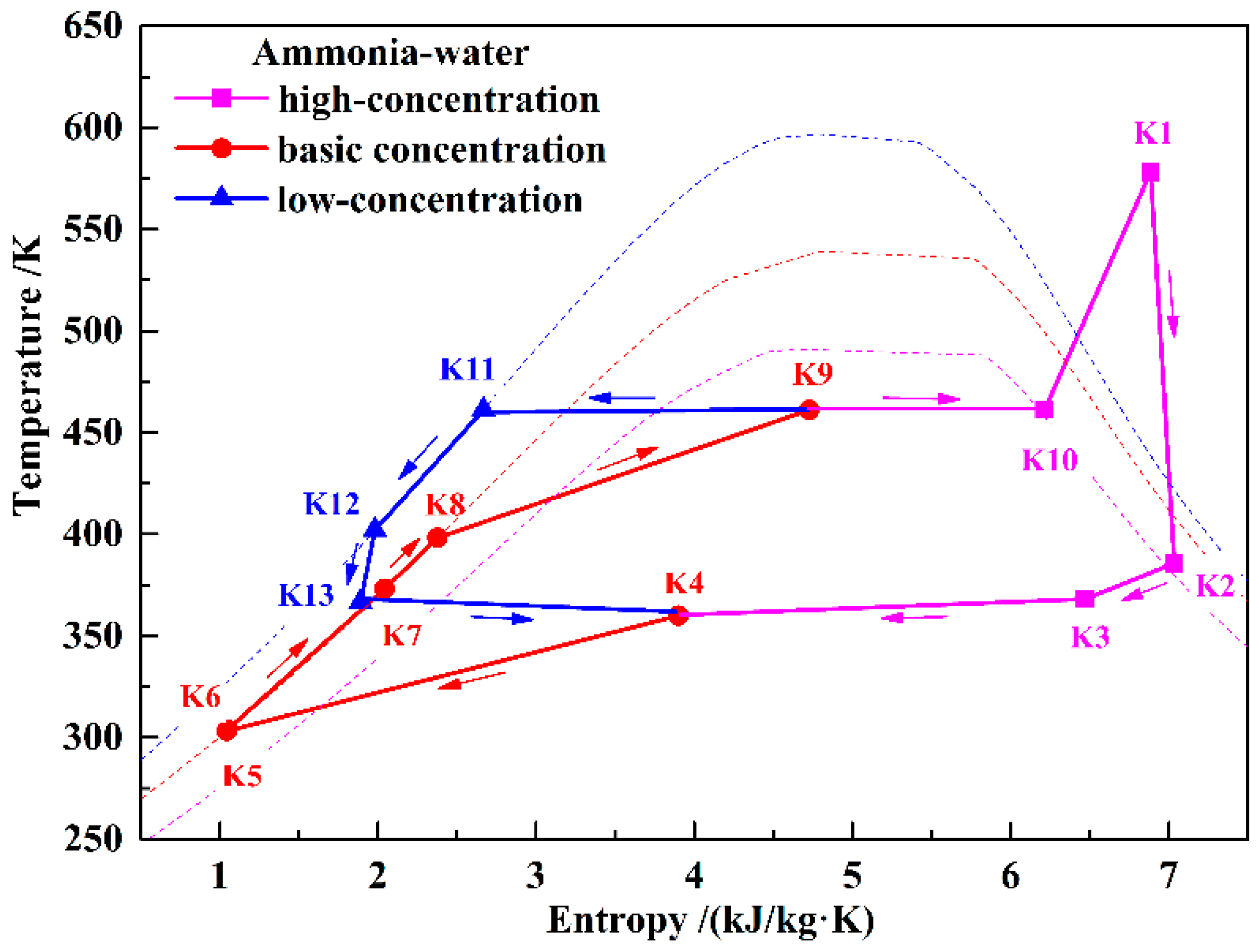
Figure 3 shows the T–s diagram of the KC system. During the discharging process, the KC turbine (KT) and the air turbines work simultaneously to generate electricity. Ammonia–water with a certain concentration has been chosen as the working fluid. In the KC system, the low-temperature basic concentration ammonia–water (BCAW) is first pumped to a high-pressure state (K6). Then, before flowing into the KC evaporator (KEVA), the BCAW is gradually heated by the exhausted gas in the KC regenerator (KR) and the low-concentration ammonia–water (LCAW) in the KC preheater (KPH). The low-temperature compression heat stored in water can also be used to preheat the BCAW in the KPH if the heat of the LCAW is insufficient. In the KEVA, the BCAW is heated by the high-temperature compression heat stored in thermal oil, and a liquid–vapor mixture is obtained (K9). In the KC separator (KSEP), the mixture is separated into a high-concentration ammonia–water (HCAW) stream (K10) and an LCAW stream (K11). The HCAW is then heated to a superheated state (K1) by the thermal oil and expanded in the KT to generate electricity. The expanded gas (K2) flows through the KR to heat the BCAW and mixes with the throttled LCAW in the mixer (MIX). Finally, the liquid–vapor mixture (K4) is cooled to a liquid state (K5) by the cooling water in the KC condenser (KCON). Before flowing back to the low-temperature storage tank, the thermal oil and water are cooled, and a hot water supply can be obtained. In this paper, only the power generation is considered in analyzing the performance of the proposed system; the heating supply is neglected.

3. Thermodynamic Analysis Model

3.1. Basic Assumptions

The Aspen HYSYS® software was used to analyze the performance of the proposed system. The classical Peng–Robinson equation of state was selected as the property package, and the properties of the working fluids were selected from the HYSYS source database. Following are the main assumptions made in this study:
  • The systems work in the steady state, and the durations of the charging and discharging processes are the same, i.e., four hours.
  • The ambient air is composed of 78% nitrogen, 20.93% oxygen, 0.03% carbon dioxide, 0.09% water, and 0.94% argon.
  • The temperature difference at the pinch point is two K in the heat exchangers that have phase changes and five K in the other heat exchangers.
  • The heat exchangers are countercurrent flow types with a reasonable pressure drop and no heat leakage.
  • The temperature decrease of the high-temperature compression heat storage tank in a cycle is two K.

3.2. Energy Analysis Model

The RTE is an important indicator for evaluating the performance of an LAES system. In this study, the RTE is defined as the power generation in the discharging process divided by the power consumption in the charging process. With the basic assumptions of the study, the durations of the charging and discharging processes are the same. Therefore, the influence of time can be neglected in the definition of the RTE. The RTE for B-LAES can be expressed as:
η RTE , B-LAES = W AT 1 + W AT 2 W AC 1 + W AC 2 + W LAP
where WAC1 and WAC2 represent the power consumption of the first-stage and second-stage compressors, respectively; WLAP represents the power consumption of the liquid air pump (LAP) (the power consumed by the other pumps is neglected because of their low values); and WAT1 and WAT2 represent the power generation of the first-stage and second-stage turbines, respectively.
The RTE of the KC-LAES can be expressed as:
η RTE , KC-LAES = W AT 1 + W AT 2 + W KT W AC 1 + W AC 2 + W LAP + W KP
where WKT represents the power generation of the KT, WKP represents the power consumption of the KC pump (KP), and the other parameters are the same as those given for Equation (1).
The compression heat utilization ratio γCH is defined as the compression heat utilized in the discharging process divided by the compression heat stored in the charging process. Therefore, the γCH for B-LAES and the KC-LAES can be expressed as:
γ CH , B-LAES = m O 10 ( h O 10 h O 19 ) m O 2 ( h O 7 h O 2 ) + m WA 7 ( h WA 7 h WA 2 )
γ CH , KC-LAES = m O 9 ( h O 9 h O 14 ) + m O 15 ( h O 15 h O 17 ) + m WA 9 ( h WA 9 h WA 10 ) m O 2 ( h O 7 h O 2 ) + m WA 7 ( h WA 7 h WA 2 )
where m and h represent the mass flow rate and specific enthalpy, respectively, and the subscripts represent the states as shown in Figure 1.
For the KC system, the efficiency and exergy efficiency can be expressed respectively as:
η KC = W net , KC Q CH , KC = W KT W KP m O 15 ( h O 15 h O 17 ) + m WA 9 ( h WA 9 h WA 10 )
η ex , KC = W net , KC E CH , KC = W KT W KP m O 15 ( e x O 15 e x O 17 ) + m WA 9 ( e x WA 9 e x WA 10 )
where QCH and ECH represent the energy and exergy of the utilized compression heat, respectively; Wnet represents the net power generation; and ex represents the specific exergy.
The improvement in the RTE can be expressed as:
η RTE , imp = η RTE , KC-LAES η RTE , B-LAES

4. Results and Discussion

In this section, the performance of the proposed KC-LAES is presented and discussed. Table 1 lists the basic design parameters of the system. In the proposed system, the air compression and expansion are both two-stage processes, and the adiabatic efficiencies of the air compressors and turbines have been selected as 85%. The pressure and temperature of the inlet air of the first-stage compressor are 0.101 MPa and 298.15 K, respectively. The mass flow rate of the air is fixed at 33.33 kg/s, and the storage pressure of the liquid air has been chosen as 0.2 MPa. In the KC subsystem, the KT is a single-stage turbine, and its adiabatic efficiency has likewise been selected as 85%. In the proposed system, the adiabatic efficiencies of all the pumps have been selected as 75%. In the discussions presented in this section, the pressure of the outlet air of the second-stage compressor (A5) is defined as the liquefaction pressure, and the pressure of the outlet air of the liquid air pump (LAP) is defined as the expansion pressure (A16). In the KC subsystem, the temperature and pressure of the outlet of the KEVA (K9) are defined as the evaporating temperature and operating pressure, respectively.

4.1. Analysis of the KC Subsystem

In the proposed system, the compression heat that can be utilized in the KC varies according to the operating parameters of the LAES. Table 2 lists the compression heat parameters utilized in the KC system under typical operating parameters (liquefaction pressure of eight MPa and expansion pressure of four MPa). With this operating condition, the total mass flow rate of thermal oil and hot water in the discharging process is 36.46 kg/s and 16.12 kg/s, respectively. A large amount of thermal oil is utilized in heating the inlet air of air turbines, and the mass flow rate is 26.88 kg/s. The surplus part can be utilized in driving the KC, and the mass flow rate is 9.58 kg/s. The hot water is not utilized in the discharging process of LAES, and the mass flow rate that can be utilized in KC is 16.12 kg/s. Besides, the inlet temperatures of thermal oil and hot water are 584.65 K and 380.15 K, respectively. As the temperature of the thermal oil is fixed, the superheated temperature of the HCAW is also constant. The influence of the basic ammonia–water concentration (xBCAW), evaporating temperature (TEVA), and operating pressure (PKC) on the performance of the KC is analyzed in this section. The power generation and efficiencies for each calculation case are also presented.
Figure 4 shows the influence of xBCAW on the performance of the KC subsystem. In the KC, the mass flow rate of BCAW (mBCAW) is the maximum flow rate, and it primarily affects the power consumption of the KP. The mass flow rate of HCAW (mHCAW)—determined by mBCAW and the vapor friction of K9 (γvap)—and the PKC value are the main factors that influence the power generation of the KT. As shown in Figure 4a, mBCAW decreases with increasing xBCAW, but γvap increases linearly. Therefore, mHCAW increases with increasing xBCAW. Since mBCAW decreases and mHCAW increases with increasing xBCAW, the power generation of the KT (WKT) increases, and the power consumption of the KP (WKP) decreases. Therefore, the net power generation of the KC (Wnet,KC) increases with the increasing xBCAW, as shown in Figure 4b. Meanwhile, the compression heat utilized in the KC (QCH) also increases with increasing xBCAW (Figure 4c). As shown in Figure 4d, the efficiency (ηKC) and exergy efficiency (ηex,KC) increase with increasing xBCAW, but the increment gradually decreases. The results with higher xBCAW are not presented, because the calculations diverge when xBCAW exceeds 85%.
Figure 5 shows the influence of TEVA on the performance of the KC subsystem. Generally, TEVA has a slight influence on the performance of the KC. As shown in Figure 5a, mBCAW decreases linearly and γvap increases linearly with increasing TEVA values. Therefore, mHCAW remains nearly constant. Correspondingly, WKT and Wnet,KC present little variation with increasing TEVA values (Figure 5b). As QCH decreases with increasing TEVA values (Figure 5c), the ηKC and ηex,KC values increase slightly with increasing TEVA values, as shown in Figure 5d.
Figure 6 shows the influence of PKC on the performance of the KC subsystem. With increasing PKC values, mBCAW increases, and γvap decreases rapidly. The mHCAW value remains nearly constant with the initial increase in PKC, but presents a decrease when PKC exceeds 12 MPa, as shown in Figure 6a. Therefore, WKT first increases and then decreases with the increase in PKC, as shown in Figure 6b. The value of WKP increases with increasing PKC values, and Wnet,KC presents a trend similar to that of WKT. As shown in Figure 6c, QCH also increases at first, and then decreases with the increase in PKC. Therefore, an optimal PKC value of 11–12 MPa is seen to achieve the highest ηKC and ηex,KC values, as shown in Figure 6d.

4.2. Analysis of the KC-LAES

The influence of the key parameters on the performance of the proposed KC-LAES is discussed in this section. In the calculations for this section, the operating parameters of the KC system are fixed (xBCAW of 85%, TEVA of 460 K, and PKC of 12 MPa). Figure 7 shows the influence of liquefaction pressure on the power generation and consumption of the proposed system. Compared with the power consumption of air compressors, the power consumption of pumps is low. Therefore, the power consumption of the pumps is not shown in the figure. With the increasing liquefaction pressure, the liquefaction ratio (γLIQ) increases, but beyond a pressure of eight MPa, the ratio increases only a little. The increasing γLIQ means an increase in the mass flow rate of the air expanded in the air turbines. As the expansion pressure is fixed, the power generation of the air turbines (WAT) presents a trend similar to that of γLIQ. Moreover, the increasing γLIQ means that more compression heat utilized in heating the inlet air of the air turbines, and less is utilized in the KC subsystem. Thus, WKT decreases with the increasing liquefaction pressure, and remains nearly constant beyond eight MPa. The value of WKT is much smaller than that of WAT. Therefore, the trend shown by WTotal is similar to that of WKT.
Figure 8 shows the influence of the liquefaction pressure on the RTEs of B-LAES and the KC-LAES. As shown in Figure 7, the power consumption of the air compressors (WAC) increases linearly with increasing liquefaction pressure. However, the increment of WTotal decreases as the liquefaction pressure increase. Therefore, the RTEs of B-LAES and the KC-LAES first increase with increasing liquefaction pressure and then present a slight decrease when the liquefaction pressure exceeds eight MPa. The RTE of the KC-LAES is improved by 4.8–7.54% over that of B-LAES in the liquefaction pressure range of six to 10 MPa, owing to the additional electricity from the KC subsystem. Since WKT decreases with increasing liquefaction pressure, ηRTE,imp also decreases with increasing liquefaction pressure.
The influence of the expansion pressure on the power generation and consumption of the proposed system is shown in Figure 9. Since the liquefaction pressure is fixed, WAC remains essentially constant. With increasing expansion pressure, γLIQ decreases rapidly, and the mass flow rate of the air expanded in the air turbines also decreases. Therefore, WAT and WTotal first increase and then decrease with the increasing expansion pressure. As γLIQ decreases, the compression heat utilized in the LAES decreases, and the part utilized in the KC subsystem correspondingly increases, leading to an increase in WKT, as shown in the figure.
Figure 10 shows the influence of the expansion pressure on the RTEs of B-LAES and the KC-LAES. As WAC is essentially constant, the RTEs present trends similar to that of WTotal, and an optimal expansion pressure value of four MPa is obtained. The value of ηRTE,imp increases markedly with the increase in expansion pressure because of the increase in WKT. The RTE of the KC-LAES is improved by 4.74–7.37% over that of B-LAES in the expansion pressure range of 2.0 to 6.0 MPa.

4.3. Performance of the KC-LAES with Typical Operating Conditions

The performance of the KC-LAES with typical operating conditions is presented in this section. Table 3 and Table 4 show the thermodynamic parameters of air, thermal oil, and water streams. As listed in Table 3, the liquefaction pressure (A5) is eight MPa, and the expansion pressure (A16) is four MPa. The mass flow rate of the inlet air of the compressor is fixed at 33.33 kg/s. After separation, the mass flow rates of the liquid and gaseous air are 27.67 kg/s and 5.66 kg/s, respectively. The temperature of the outlet air of AT1 and AT2 are 614.44 K and 618.4 K, respectively. Considering a reasonable temperature difference between hot and cold fluids in the heat exchangers, the storage temperatures of the thermal oil and water are 586.65 K and 380.15 K, respectively. In the basic assumptions, the temperature decrease of the high-temperature compression heat storage tank in a cycle is two K. Therefore, the temperatures of the outlet fluid from the high-temperature thermal oil tank (HOT) and the high-temperature water tank (HWT) are 584.65 K and 378.15 K, respectively. With the operating conditions given in this section, the mass flow rates of the thermal oil utilized in the air turbines and the KC subsystem are 26.88 kg/s and 9.58 kg/s, respectively. In the discharging process, the temperature of the inlet air to the air turbines has been chosen as 579.65 K. The temperatures of the expanded and exhausted air are 391.93 K and 324.68 K, respectively. In the KC of the presented case, the heat of the LCAW is sufficient to preheat the cold working fluid, and the compression heat stored in water is not necessary. Therefore, the thermodynamic parameter values for WA9 and WA10 are the same.
Table 5 lists the thermodynamic parameters of the ammonia–water streams in the KC subsystem. In addition to temperature, pressure, and mass flow rate, the concentration (x) and vapor fraction (γvap) of each stream are also presented. In the present case, the xBCAW value has been chosen as 85%, and the calculated results for xHCAW and xLCAW are 90.94% and 61.26%, respectively. The TEVA and PKC values have been selected as 460 K and 12 MPa, respectively. Considering the minimum temperature difference of the KC superheater (KSH), the temperature of the inlet fluid to the KT has been chosen as 582.65 K. The mBCAW and mHCAW values are 3.25 kg/s and 2.60 kg/s, respectively. In the KCON, the liquid–vapor mixture is condensed by the cooling water, and the condensation pressure and temperature are 0.89 MPa and 300 K, respectively.
Table 6 shows a comparison of the calculation results for B-LAES and the KC-LAES with typical operating parameters. According to the calculation results, the performance of the system is significantly improved by the introduction of the KC. The utilization ratio of the compression heat is increased from 54.74% to 74.27%, and the RTE is correspondingly improved. With the same operating parameters, the RTEs of the B-LAES and the KC-LAES are 52.16% and 57.18%, respectively. Owing to the increase in the power generation, an energy storage density of 98.01 kWh/m3 is obtained in the KC-LAES, which is much higher than that of the B-LAES.

5. Conclusions

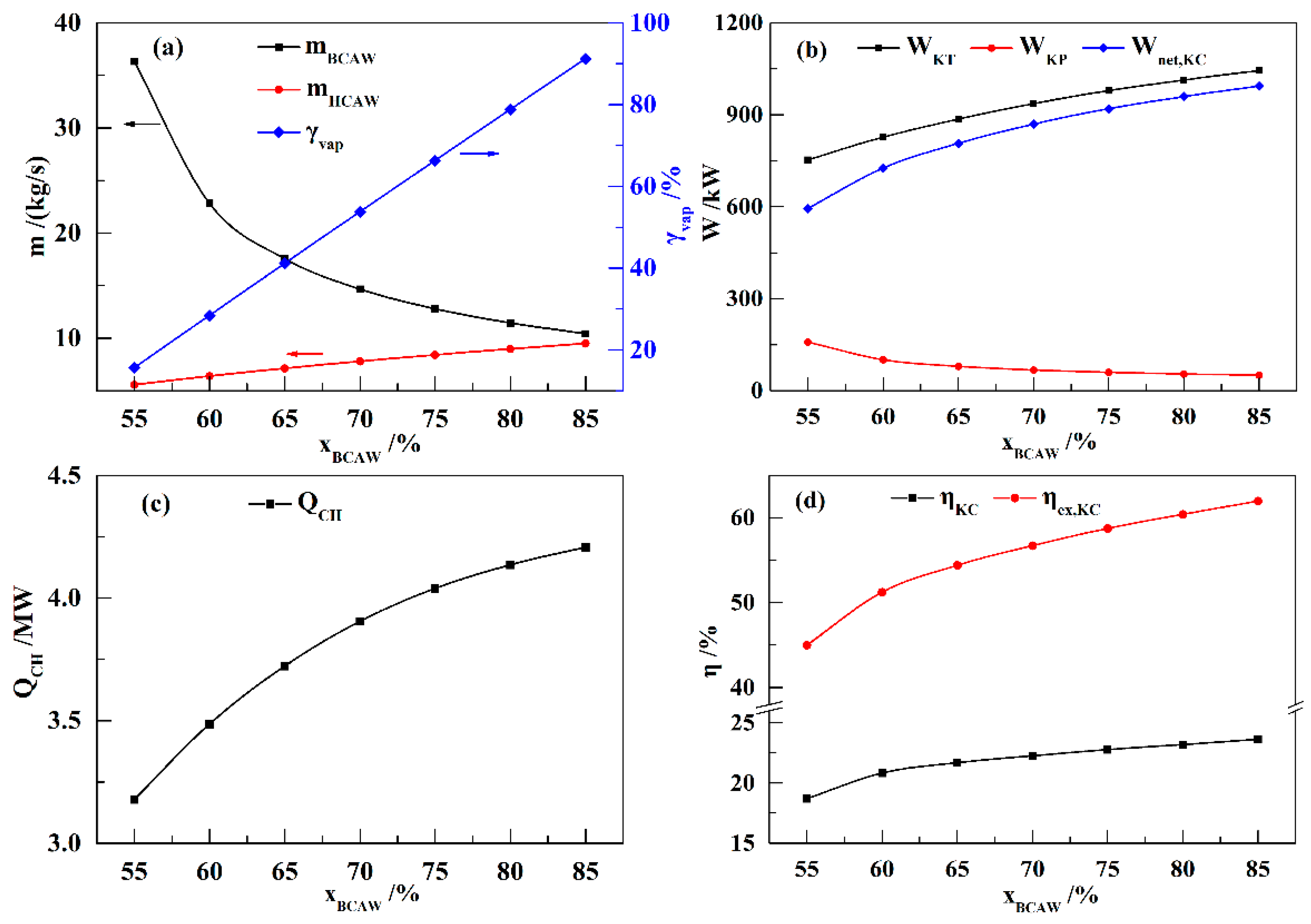
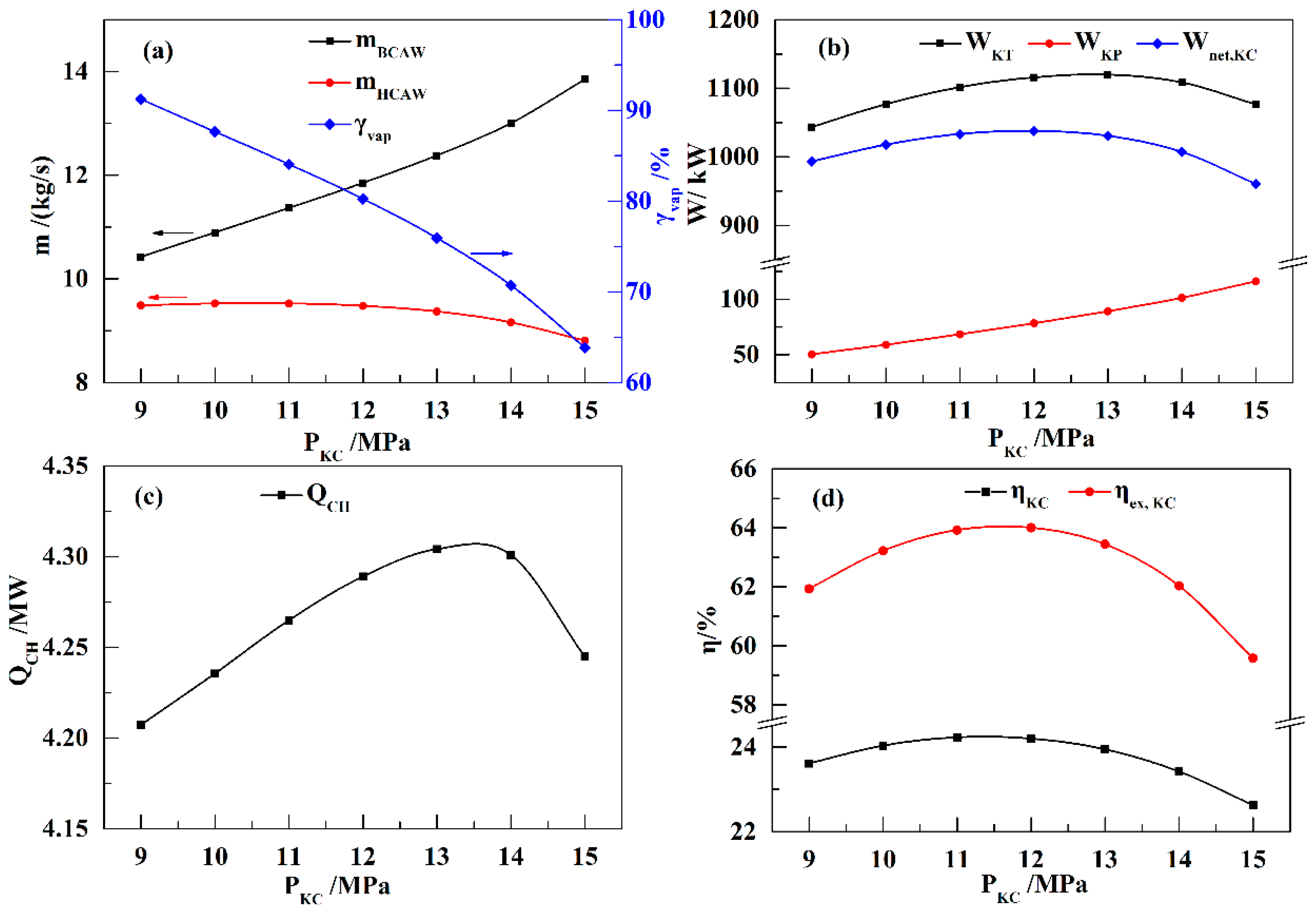
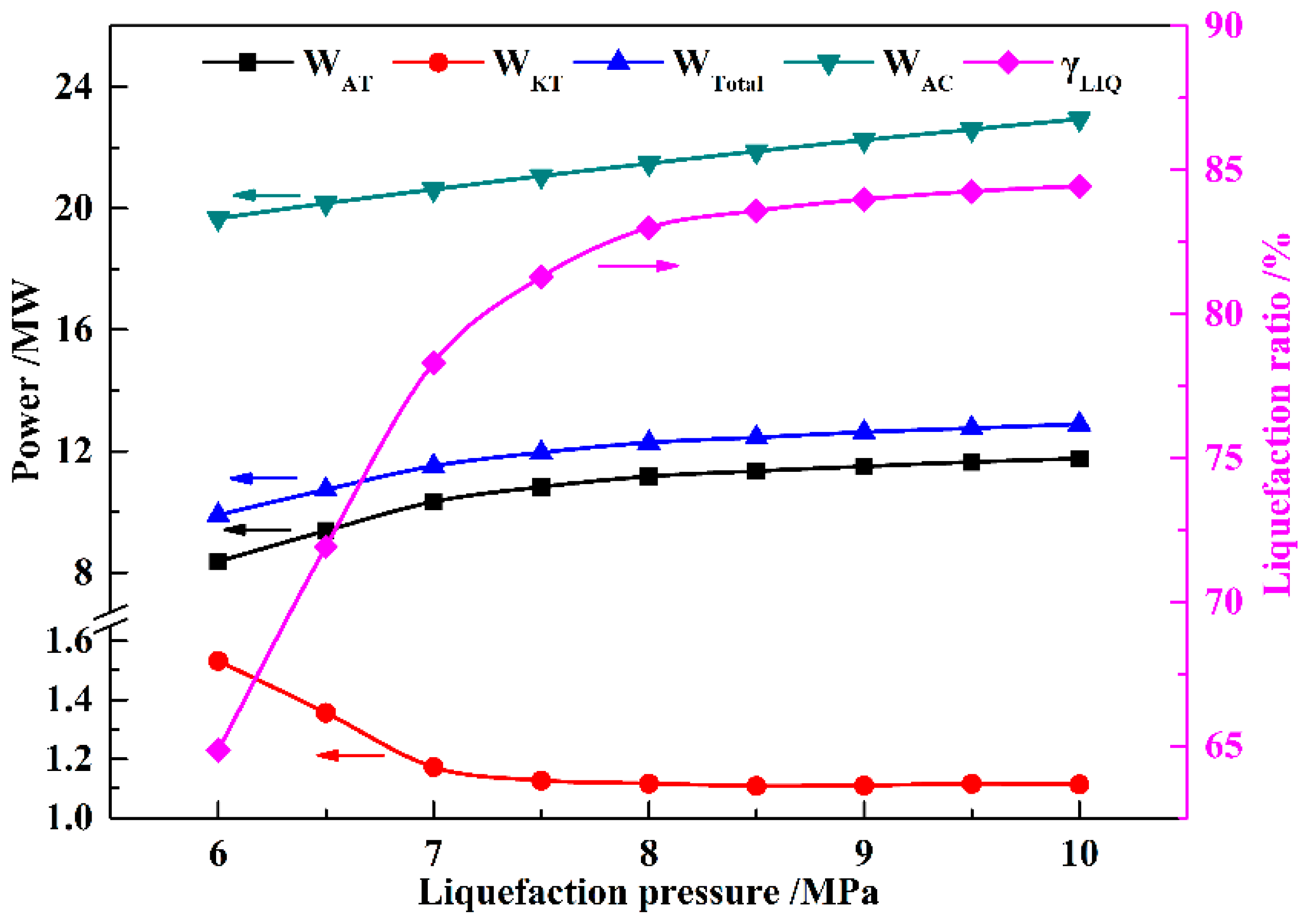
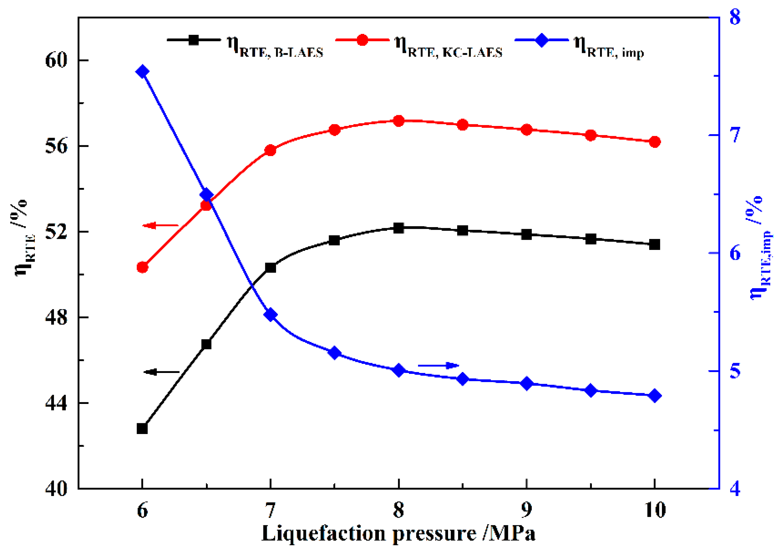
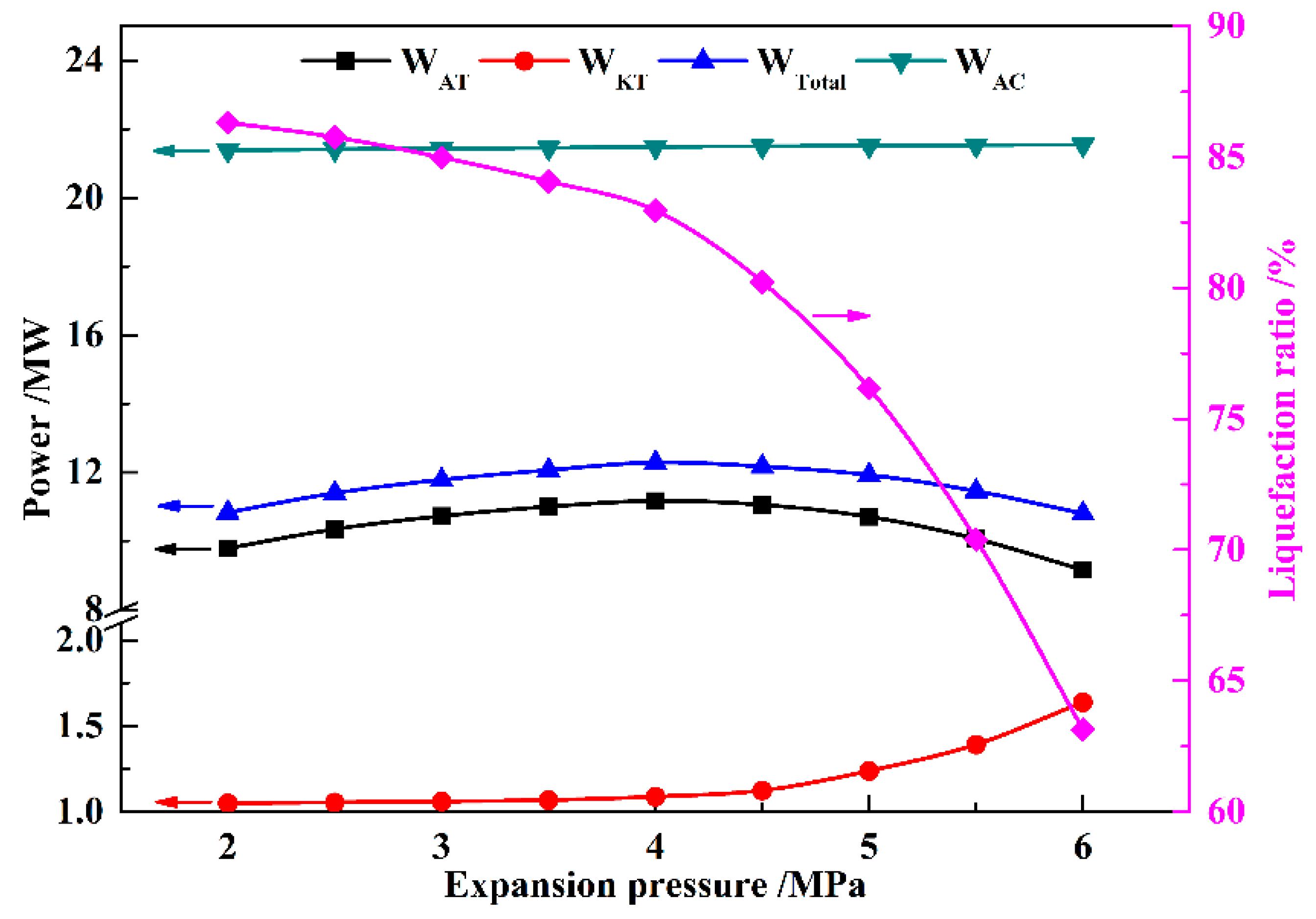
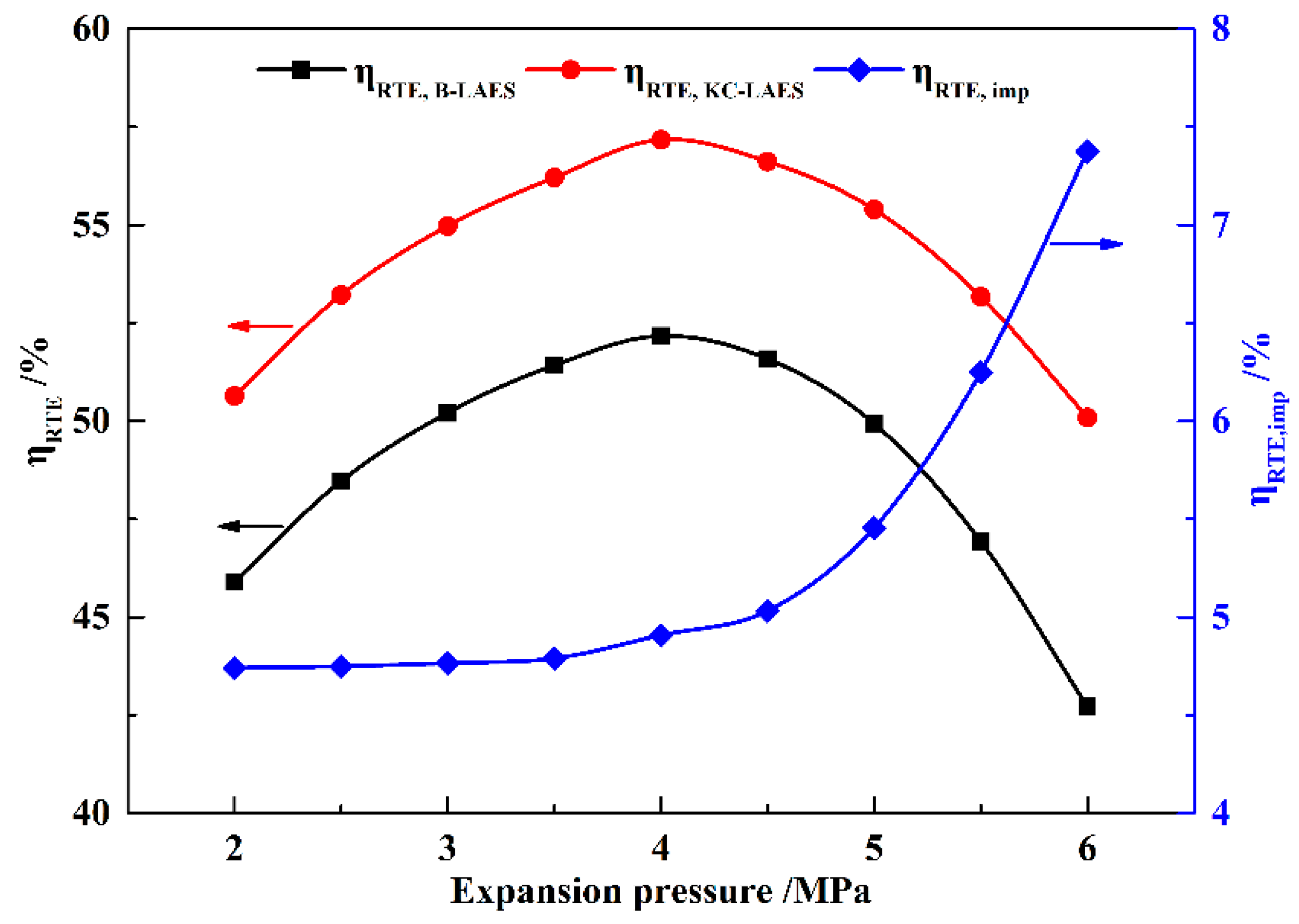
In this paper, a novel integrated system based on liquid air energy storage (LAES) and Kalina cycle (KC), called KC-LAES, has been proposed and analyzed. In baseline LAES (B-LAES), the compression heat is surplus because of the low liquefaction ratio. Therefore, a KC system is introduced into the LAES to utilize the surplus compression heat to generate additional electricity. An energetic model was developed to assess the performance of the proposed system. In the analysis of the KC, the influence of the working fluid concentration, evaporating temperature, and operating pressure was discussed. The power generation of the KC turbine, efficiency, and exergy efficiency for each calculation case was presented. According to the calculation results, the evaporating temperature has less influence on the performance of the KC, and the optimal working fluid concentration and operating pressure are 85% and 12 MPa, respectively. In the analysis of the KC-LAES, the influence of liquefaction and of expansion pressure was presented. The calculation results indicate that the introduction of the KC can notably improve the performance of LAES. The RTE of the KC-LAES is 57.18%, compared with that of B-LAES, 52.16%, with a liquefaction pressure value of eight MPa and an expansion pressure value of four MPa.

Author Contributions

Conceptualization, T.Z. and X.X.; Formal analysis, T.Z. and X.Z.; Funding acquisition, X.X. and S.M.; Investigation, X.Z., X.X., and G.W.; Methodology, T.Z. and X.Z.; Supervision, G.W. and S.M.; Writing—original draft, T.Z.; Writing—review and editing, X.Z., X.X., G.W. and S.M.

Funding

This work was supported by the Foundation for Innovative Research Groups of the National Natural Science Foundation of China (51621065), and the Scientific and Technological Project of Qinghai Province (2017-GX-101).

Conflicts of Interest

The authors declare no conflict of interest.

Abbreviations

ACair compressor
ATair turbine
B-LAESbaseline LAES
BCAWbasic concentration ammonia–water
CAEScompressed air energy storage
HCAWhigh-concentration ammonia–water
HEheat exchanger
HMThigh-temperature methane tank
HOThigh-temperature thermal oil tank
HPThigh-temperature propane tank
HWShot water supply
HWThigh-temperature water tank
KCKalina cycle
KC-LAESintegrated energy system based on LAES and KC
KCONKC condenser
KEVAKC evaporator
KPKC pump
KPHKC preheater
KRKC regenerator
KSEPKC separator
KSHKC superheater
KTKC turbine
LAESliquid air energy storage
LAPliquid air pump
LATliquid air tank
LCAWlow-concentration ammonia–water
LMTlow-temperature methane tank
LOTlow-temperature thermal oil tank
LPTlow-temperature propane tank
LWTlow-temperature water tank
MIXmixer
PHESpump hydro energy storage
RTEround-trip efficiency
SEPseparator
TVthrottle valve
Symbols
Eexergy (MW)
exspecific exergy (kJ/kg)
hspecific enthalpy (kJ/kg)
mmass flow rate (kg/s)
Ppressure (MPa)
Qenergy (MW)
sspecific entropy (kJ/kg·K)
Ttemperature (K)
Wpower (MW)
xammonia concentration (%)
ηefficiency (%)
γratio (%)
Streams
Aair
Ccooling water
KKC working fluid
Mmethane
Othermal oil
PRpropane
WAwater
Other Subscripts
CHcompression heat
EVAevaporating
exexergy
impimprovement
LIQliquefaction ratio
vapvapor

References

  1. Mei, S.; Wang, J.; Tian, F.; Chen, L.; Xue, X.; Lu, Q.; Zhou, Y.; Zhou, X. Design and Engineering Implementation of Non-supplementary Fired Compressed Air Energy Storage System: TICC-500. Sci. China Tech. Sci. 2015, 58, 600–611. [Google Scholar] [CrossRef]
  2. Raju, M.; Khaitan, S.K. Modeling and Simulation of Compressed Air Storage in Caverns: A Case Study of The Huntorf Plant. Appl. Energy 2012, 89, 474–481. [Google Scholar] [CrossRef]
  3. Smith, E. Storage of Electrical Energy Using Supercritical Liquid Air. Proc. Inst. Mech. Eng. 1977, 191, 289–298. [Google Scholar] [CrossRef]
  4. Morgan, R.; Nelmes, S.; Gibson, E.; Brett, G. Liquid Air Energy Storage–Analysis and First Results from a Pilot Scale Demonstration Plant. Appl. Energy 2015, 137, 845–853. [Google Scholar] [CrossRef]
  5. Ameel, B.; T’Joen, C.; Kerpel, K.D.; Jaeger, P.D.; Huissemune, H.; Belleghem, M.V.; Paepe, M.D. Thermodynamic Analysis of Energy Storage with a Liquid Air Rankine Cycle. Appl. Therm. Eng. 2013, 52, 130–140. [Google Scholar] [CrossRef]
  6. Sciacovelli, A.; Vecchi, A.; Ding, Y. Liquid Air Energy Storage (LAES) with Packed Bed Cold Thermal Storage—From Component to System Level Performance through Dynamic Modelling. Appl. Energy 2017, 190, 84–98. [Google Scholar] [CrossRef]
  7. Xue, X.; Wang, S.; Zhang, X.; Cui, C.; Chen, L.; Zhou, Y.; Wang, J. Thermodynamic Analysis of a Novel Liquid Air Energy Storage System. Phys. Procedia 2015, 67, 733–738. [Google Scholar] [CrossRef] [Green Version]
  8. Guizzi, G.L.; Manno, M.; Tolomei, L.M.; Vitali, R.M. Thermodynamic Analysis of a Liquid Air Energy Storage System. Energy 2015, 93, 1639–1647. [Google Scholar] [CrossRef]
  9. Howe, T.A.; Pollman, A.G.; Gannon, A.J. Operating Range for a Combined, Building-Scale Liquid Air Energy Storage and Expansion System: Energy and Exergy Analysis. Entropy 2018, 20, 770. [Google Scholar] [CrossRef]
  10. Tafone, A.; Romagnoli, A.; Li, Y.; Borri, E.; Comodi, G. Techno-economic Analysis of a Liquid Air Energy Storage (LAES) for Cooling Application in Hot Climates. Energy Procedia 2017, 105, 4450–4457. [Google Scholar] [CrossRef]
  11. Li, Y.; Cao, H.; Wang, S.; Jin, Y.; Li, D.; Wang, X.; Ding, Y. Load Shifting of Nuclear Power Plants Using Cryogenic Energy Storage Technology. Appl. Energy 2014, 113, 1710–1716. [Google Scholar] [CrossRef]
  12. Zhang, T.; Chen, L.; Zhang, X.; Mei, S.; Xue, X.; Zhou, Y. Thermodynamic Analysis of a Novel Hybrid Air Energy Storage System based on the Utilization of LNG Cold Energy. Energy 2018, 155, 641–650. [Google Scholar] [CrossRef]
  13. Antonelli, M.; Barsali, S.; Desideri, U.; Giglioli, R.; Paganucci, F.; Pasini, G. Liquid Air Energy Storage: Potential and Challenges of Hybrid Power Plants. Appl. Energy 2017, 194, 522–529. [Google Scholar] [CrossRef]
  14. Al-Zareer, M.; Dincer, I.; Rosen, M.A. Analysis and Assessment of Novel Liquid Air Energy Storage System with District Heating and Cooling Capabilities. Energy 2017, 141, 792–802. [Google Scholar] [CrossRef]
  15. She, X.; Peng, X.; Nie, B.; Leng, G.; Zhang, X.; Weng, L.; Tong, L.; Zheng, L.; Wang, L.; Ding, Y. Enhancement of Round-Trip Efficiency of Liquid Air Energy Storage through Effective Utilization of Heat of Compression. Appl. Energy 2017, 206, 1632–1642. [Google Scholar] [CrossRef]
  16. Peng, X.; She, X.; Cong, L.; Zhang, T.; Li, C.; Li, Y.; Wang, L.; Tong, L.; Ding, Y. Thermodynamic Study on the Effect of Cold and Heat Recovery on Performance of Liquid Air Energy Storage. Appl. Energy 2018, 221, 86–99. [Google Scholar] [CrossRef]
  17. Tafone, A.; Borri, E.; Comodi, G.; Broek, M.; Romagnoli, A. Preliminary Assessment of Waste Heat Recovery Solution (ORC) to Enhance the Performance of Liquid Air Energy Storage System. Energy Procedia 2017, 142, 3609–3616. [Google Scholar] [CrossRef]
  18. Tafone, A.; Borri, E.; Comodi, G.; Broek, M.; Romagnoli, A. Liquid Air Energy Storage Performance Enhancement by Means of Organic Rankine Cycle and Absorption Chiller. Appl. Energy 2018, 228, 1810–1821. [Google Scholar] [CrossRef]
  19. Zhang, X.; He, M.; Zhang, Y. A Review of Research on the Kalina Cycle. Renew. Sustain. Energy Rev. 2012, 16, 5309–5318. [Google Scholar] [CrossRef]
  20. Wang, J.; Dai, Y.; Gao, L. Exergy Analyses and Parametric Optimizations for Different Cogeneration Power Plants in Cement Industry. Appl. Energy 2009, 86, 941–948. [Google Scholar] [CrossRef]
  21. Sun, F.; Zhou, W.; Ikegami, Y.; Nakagami, K.; Su, X. Energy-exergy Analysis and Optimization of the Solar-boosted Kalina Cycle System 11 (KCS-11). Renew. Energy 2014, 66, 268–279. [Google Scholar] [CrossRef]
  22. Wang, J.; Yan, Z.; Zhou, E.; Dai, Y. Parametric Analysis and Optimization of a Kalina Cycle Driven by Solar Energy. Appl. Therm. Eng. 2013, 50, 408–415. [Google Scholar] [CrossRef]
  23. Pan, Z.; Wang, J.; Dai, Y. Thermodynamic analysis of an integrated energy system based on compressed air energy storage (CAES) system and Kalina cycle. Energy Convers. Manag. 2015, 98, 161–172. [Google Scholar] [CrossRef]
  24. Li, R.; Wang, H.; Yao, E.; Zhang, S. Thermo-Economic Comparison and Parametric Optimizations among Two Compressed Air Energy Storage System Based on Kalina Cycle and ORC. Energies 2017, 10, 15. [Google Scholar] [CrossRef]
Figure 1. Schematic of the Kalina cycle liquid air energy storage (KC-LAES) system.
Entropy 21 00220 g001
Figure 2. T–s diagram of the baseline liquid air energy storage (B-LAES) system.
Entropy 21 00220 g002
Figure 3. T–s diagram of the KC subsystem.
Entropy 21 00220 g003
Figure 4. Influence of xBCAW on the performance of the KC (TEVA = 460 K, PEVA = 9 MPa): (a) mBCAW, mHCAW, and γvap; (b) WKT, WKP, and Wnet,KC; (c) QCH; (d) ηKC and ηex,KC.
Entropy 21 00220 g004
Figure 5. Influence of TEVA on the performance of the KC (xBCAW = 85%, PEVA = nine MPa): (a) mBCAW, mHCAW, and γvap; (b) WKT, WKP, and Wnet,KC; (c) QCH; (d) ηKC and ηex,KC.
Entropy 21 00220 g005
Figure 6. Influence of PKC on the performance of the KC (xBCAW = 85%, TEVA = 460 K): (a) mBCAW, mHCAW, and γvap; (b) WKT, WKP, and Wnet,KC; (c) QCH; (d) ηKC and ηex,KC.
Entropy 21 00220 g006
Figure 7. Influence of liquefaction pressure on WAT, WKT, WTotal, WAC, and γLIQ (with an expansion pressure value of four MPa).
Entropy 21 00220 g007
Figure 8. Influence of liquefaction pressure on round-trip efficiencies (RTEs) (with an expansion pressure value of four MPa).
Entropy 21 00220 g008
Figure 9. Influence of expansion pressure on WAT, WKT, WTotal, WAC, and γLIQ (with a liquefaction pressure value of eight MPa).
Entropy 21 00220 g009
Figure 10. Influence of expansion pressure on RTEs (with a liquefaction pressure value of eight MPa).
Entropy 21 00220 g010
Table 1. Basic design parameters of the KC-LAES system. KT: KC turbine.
ParametersUnitsValues
Ambient pressureMPa0.101
Ambient temperatureK298.15
Compression stage2
Expansion stage2
Air compression durationh4
Air expansion durationh4
Air flow rate of compressorkg/s33.33
Adiabatic efficiency of air compressors%85
Adiabatic efficiency of air turbines%85
Adiabatic efficiency of KT%85
Adiabatic efficiency of pumps%75
Storage pressure of liquid airMPa0.2
Table 2. Compression heat and cooling water parameters utilized in the KC system.
ParametersUnitsValues
Inlet temperature of thermal oilK584.65
Mass flow rate of thermal oilkg/s9.58
Inlet temperature of hot waterK380.15
Mass flow rate of hot waterkg/s16.12
Condensation temperatureK300.15
Inlet temperature of cooling waterK298.15
Outlet temperature of cooling waterK303.15
Table 3. Thermodynamic parameters of air streams.
StreamT (K)P (MPa)m (kg/s)StreamT (K)P (MPa)m (kg/s)
A1298.150.1033.33A13173.150.195.66
A2614.440.98733.33A14293.150.185.66
A3385.150.96733.33A1585.410.227.67
A4313.150.94733.33A1688.02427.67
A5618.40833.33A17169.043.9627.67
A6385.157.9233.33A18308.983.9227.67
A7313.157.8433.33A19373.153.8827.67
A8188.157.7633.33A20579.653.8427.67
A9101.357.6833.33A21374.050.56527.67
A1085.410.233.33A22579.650.55527.67
A1185.410.227.67A23391.930.1127.67
A1285.410.195.66A24324.680.127.67
Table 4. Thermodynamic parameters of thermal oil and water streams.
StreamT (K)P (MPa)m (kg/s)StreamT (K)P (MPa)m (kg/s)
O1378.150.136.46O18378.150.19.58
O2378.150.1236.46O19378.150.1426.88
O3378.150.1218.7O20378.150.126.88
O4586.650.118.7O21378.150.136.46
O5378.150.1217.76WA1308.150.116.12
O6586.650.117.76WA2308.150.216.12
O7586.650.136.46WA3308.150.28.36
O8584.650.136.46WA4380.150.188.36
O9584.650.1636.46WA5308.150.27.76
O10584.650.1626.88WA6380.150.187.76
O11584.650.1613.28WA7380.150.1816.12
O12378.150.1413.28WA8378.150.1816.12
O13584.650.1613.6WA9378.150.216.12
O14378.150.1413.6WA10378.150.216.12
O15584.650.169.58WA11308.150.1816.12
O16534.350.149.58WA12308.150.116.12
O17387.550.129.58
Table 5. Thermodynamic parameters of ammonia–water streams.
StreamT (K)P (MPa)m (kg/s)x (%)γvap (%)
K1579.6511.942.6090.94100
K2369.880.92.6090.9497.46
K3324.230.8952.6090.9481.49
K4324.690.8953.258568.88
K53000.893.25850
K6303.2612.363.25850
K7367.5512.243.25850
K8385.512.123.25850
K9460123.258580.24
K10460122.6090.94100
K11460120.6561.260
K12369.6511.940.6561.260
K13369.650.90.6561.2617.85
Table 6. Calculation results of the B-LAES and KC-LAES.
ParametersUnitsB-LAESKC-LAES
Compressor power consumptionMW21.2221.22
Pump power consumptionMW0.1760.255
Air turbine power generationMW11.1611.16
KT power generationMW1.12
Round-trip efficiency%52.1657.18
Compression heat utilization ratio%54.7474.27
Liquefaction ratio%83.0183.01
Mass of stored liquid airt398.4398.4
Volume of stored liquid airm3501.2501.2
Specific consumption of liquid airkWh/kg0.21480.2156
Electricity energy storage densitykWh/m389.0798.01

