Optimization of Biomass-Fuelled Combined Cooling, Heating and Power (CCHP) Systems Integrated with Subcritical or Transcritical Organic Rankine Cycles (ORCs)


Abstract
: This work is focused on the thermodynamic optimization of Organic Rankine Cycles (ORCs), coupled with absorption or adsorption cooling units, for combined cooling heating and power (CCHP) generation from biomass combustion. Results were obtained by modelling with the main aim of providing optimization guidelines for the operating conditions of these types of systems, specifically the subcritical or transcritical ORC, when integrated in a CCHP system to supply typical heating and cooling demands in the tertiary sector. The thermodynamic approach was complemented, to avoid its possible limitations, by the technological constraints of the expander, the heat exchangers and the pump of the ORC. The working fluids considered are: n-pentane, n-heptane, octamethyltrisiloxane, toluene and dodecamethylcyclohexasiloxane. In addition, the energy and environmental performance of the different optimal CCHP plants was investigated. The optimal plant from the energy and environmental point of view is the one integrated by a toluene recuperative ORC, although it is limited to a development with a turbine type expander. Also, the trigeneration plant could be developed in an energy and environmental efficient way with an n-pentane recuperative ORC and a volumetric type expander.1. Introduction
Combined cooling, heating, and power (CCHP) systems are mainly based on the integration of a combined heat and power (CHP) unit, also known as a prime mover, which generates electricity and heat, and a thermally driven chiller which produces a cooling effect. These systems lead to higher overall efficiencies in comparison with conventional generation in large power plants; they also allow primary energy savings and emission reduction and enhance the reliability of the supply network [1]. The use of renewable energy sources, such as biomass, or waste heat recovery to drive CCHP might reinforce these advantages, but these types of plants are at an early stage of development along with some of the technologies involved [2], especially at micro and small-scale.
The development of bio-fuelled CCHP systems requires an optimal design both from the points of view of the subsystem’s integration and the subsystem’s development itself. Firstly, the optimal performance of the theoretical configurations is strongly linked to the way the different subsystems involved are coupled. Two different configurations can be proposed, from a theoretical approach, to generate power, heating and cooling from biomass combustion through the integration of a boiler, a prime mover and a thermally driven chiller: “parallel” or “cascade” coupling. The comparison of both types applied to a biomass fuelled trigeneration plant clearly shows a preference for the latter [3], where the different energy products are sequentially generated thus achieving a higher performance. However, when assessing the state-of-the-art of the possible technologies that might integrate a CCHP system based on biomass combustion it is clear that this exclusive “cascade” integration might not always be possible due to the lack of prime mover units specifically designed for this application, in terms of their power size and their operation characteristics [4]. Moreover, the limitations of the subsystems involved (boiler, prime mover and chiller) might condition the plant configuration to a mix between both theoretical integrations (“parallel” and “cascade”).
Secondly, there is a need for the development of prime movers that can be optimally integrated in a trigeneration system, and steam cycles have a great potential for this application [1,5], specifically at medium and small-scale through Organic Rankine Cycles (ORCs). Previous works by Al-Sulaiman et al. [6,7] and Huang et al. [8] with regard to biomass fired trigeneration through ORC are mainly focused on a strictly thermodynamic, environmental or techno-economic approach, respectively. However, the optimal design of ORC systems taking several practical constraints into account can lead to the selection of different optimal operating conditions and working fluids [9]. The method described in the referred work should therefore be preferred to obtain optimal ORC practical design guidelines rather than the solely thermodynamic approach.
Hence, the main objective of the present study is to provide general guidelines for the design of an ORC unit to be optimally integrated in a biomass fuelled trigeneration system, including working fluid, expander inlet pressure and temperature, superheating degree, presence of a recuperator, transcritical versus subcritical operation, amongst others. This is carried out through a thermodynamic assessment in combination with the evaluation of the parameters that characterize the main cycle components (expander, heat exchangers and feed pump), in order to avoid the exclusive thermodynamic benchmarking of candidate working fluids.
In addition, the optimal CCHP system should be assessed to investigate if it does indeed accomplish the benefits of multi-generation systems at different nominal loads, from an energy and environmental perspective. This analysis is based on the main conclusions of previous works [4,5,10], which show that the feasibility of CCHP in comparison to conventional generation is limited both by the technologies involved and the cooling-to-heating ratio.
All the analysis carried out in the present work is focused on the development of micro and small-scale (0.5–250 kWe) CCHP systems based on biomass combustion, with the main aim of contributing to the development of this promising technology that will be responsible for a high share of the heat supply demand in the future [11].
2. Methodology
A thermodynamic model was developed to optimize the performance of a bio-fuelled CCHP plant. The system proposed consists of a biomass boiler, on ORC and a thermally driven chiller. A list of candidate working fluids for the ORC was proposed, as well as the characteristic heat source and sink profiles of the subsystems involved. General design rules can be established by examining a discrete number of boundary conditions and working fluids, subject to the technical parameters of the main ORC equipment (heat exchangers, expander and pump).
2.1. CCHP System Description
Figure 1 depicts a schematic diagram of the CCHP plant based on biomass combustion. The biomass is fed to the boiler where its combustion heats up the fluid of an intermediate heat transfer loop (12). The heat source loop enters the evaporator generating vapor (1) which expands in a turbine, thereby producing useful work. Then, the fluid exhausted from the expander (2) enters the low pressure side of the recuperator, or internal heat exchanger (IHE), and the fluid exported from the pump (5) is conveyed to high pressure inlet of the IHE, thereby transferring heat from the low pressure to high pressure side. The thermal efficiency of the ORC system is then augmented by adding the IHE. The cycle rejects heat at a low pressure in the condenser by means of a cold fluid (water: 7–8) which is used to supply a certain heating demand or to drive a cooling unit to supply a cooling demand. Finally, the flue gases through the stack (11), at a higher temperature than the acid dew point limit [12] can still be used to rise the temperature of the ORC cold fluid (8) before driving the cooling unit or supplying a certain heat demand.
It should be noted that a classical biomass ORC system can be more complex than the design presented in Figure 1, mainly in terms of the different evaporation stages [13], which are typical of bio-fuelled ORCs in the power range of 500 kWe–2 MWe. However, the present work is focused on small-scale units and hence the plant layout should remain as simple as possible.
The operating conditions of the ORC are limited by the heat source and sink characteristics. On the one hand, the heat source profile corresponds to an intermediate heat transfer loop, which temperature is limited due to thermal stability issues and it is typically in the range of 300–320 °C [14]. On the other hand, there are two possible thermally driven cooling units to couple with the condenser of an ORC: Absorption and adsorption units. The nominal operating conditions of these technologies are summarized in Table 1, based on the state of the art of such units.
2.2. Working Fluids
A large number of candidate working fluids have been assessed in the available scientific literature. However, only a few of them are used in the ORC units with sufficient technical maturity for large-scale competitive commercialization, since they match the needs of the corresponding applications. The working fluid selection criteria of this work focuses on the most common fluids used in commercial units available on the market, specifically the ones with higher critical temperature, which are the best candidates for a CHP application, according to the results obtained in previous works [15]: n-pentane, octamethyltrisiloxane (MDM) and toluene. To complement this list of fluids, and hence widen the possible results of this study with the inclusion of non-commercial fluids with similar characteristics, an additional high temperature alkane and siloxane were added: n-heptane and dodecamethylcyclohexasiloxane (D6).
2.3. Model Description
This section describes the thermodynamic model of the CCHP system. All the models proposed in this section were developed under the EES environment [16] and the thermodynamic properties of the working fluids were calculated using CoolProp 3.0 [17] and the EES-Coolprop interface. Part of the model was developed in previous works [15] and it was modified to include the biomass combustion and the thermally driven cooling units. The model main equations are briefly presented hereunder. A more detailed description of the model equations is available in previous publications [9,18,19].
In the optimization process, the heat exchangers are modelled by imposing a pinch point. However, since the goal is also to evaluate the required size of the heat exchangers (evaporator, condenser and IHE), the computation of the required conductance is included in the model. In addition, the evaporator is discretized to allow the cycle computation both in subcritical and transcritical operation. The number of nodes (N = 100) of the discretization has to be adequate to provide a sufficient accuracy, but not too high in order to avoid excessive computational effort.
The heat transfer rate in the heat exchangers of the cycle (evaporator, condenser and recuperator) is expressed as a function of the mass flow rate (ṁ) and the enthalpy difference (Δh):
The heat exchanger performance is determined by:
providing a “thermal indicator” as a first approach to the heat exchanger design. The temperature difference ΔT is the logarithmic mean temperature difference (LMTD) between the corresponding fluids and the organic working fluid.
The main outputs of the thermodynamic model are the first and second law efficiencies of the cycle, defined by Equations (3) and (4) [6]:
where Ẇnet is the net power output of the cycle (Ẇexp−Ẇpp). Q̇heating and Q̇cooling are the heat and cool rates generated by the CCHP plant. Ėbiomass is the exergy flow rate of the biomass, which has been largely demonstrated to be satisfactorily approximated to its higher heating value [20]. Ėheating and Ėcooling are the exergy flow rates of the CCHP system heating and cooling productions, which are calculated according to Equations (5) and (6), respectively:
where, as an approximation, Theating and Tcooling are the average temperatures of the ORC condenser cooling fluid loop and the chilled water loop of the absorption/adsorption unit (see Table 1), respectively.
Two technological parameters have been included as a model output to consider the preliminary design of the expander: one regarding the expander as a turbine and the second as a volumetric type. In the case of a turbine type expander, the size parameter (SP) is a significant parameter for predicting the efficiency penalties related to flow compressibility and/or small blade dimensions [21]. The SP accounts for the actual turbine dimensions according to Equation (7) [22]:
To assess the possibility of including a volumetric expander (piston, scroll, screw and vane expanders), the volume coefficient (VC) is also evaluated. The VC is defined in the previous works [15] as the ratio of the outlet volumetric flow divided with the output power, as shown in Equation (8):
Both the size parameter (turbines) and the volume coefficient (volumetric expanders) provide additional information about the preliminary design of the ORC, from a technological point of view. There are some typical values in the subject literature for these two parameters. These values should be used as general design guidelines, not as strict limits. First, the size parameter is a technical constraint of the expander when considering it as a turbine type. The SP has been used by other authors to study the size characteristics of the expander in the ORC system. According to subject literature [21], the SP is comprised between 0.02 and 1 m in ORC turbines for subcritical and transcritical operation. As shown in Equation (7), “the parameter SP, which is a function solely of the thermodynamic cycle and power output, is proportional for a given (optimized) value of Ds to the actual turbine dimensions: low SP values penalize the turbine efficiency because of large losses caused by the increase in relative blade thickness, clearance, roughness, etc.” [21]. When considering a volumetric device as the expander, the volume coefficient should be assessed to evaluate the preliminary design of the ORC unit. A screening of refrigeration and heat pump applications shows that for a compressor, this ratio (defined with the exhaust volume flow rate) is roughly between 2.5 × 10⁻⁴ and 6.0 × 10⁻⁴ m³/kJ [23].
Hence, the evaluation of the SP and VC results should shed light on the possibility of implementing the ORCs assessed, from the expander point of view.
2.4. Optimization
Parametric optimization was performed to maximize the second law efficiency of the system to generate cooling, heating and power. Identifying the maximum second law efficiency is a multivariate, non-linear optimization problem and is solved using the direct search optimization algorithm [24]. The optimization variables are the following:
Continuous variables: expander inlet pressure, superheating degree and return temperature of the heat source loop.
Discrete variables: different working fluids selected for the present work and cooling generation through absorption or adsorption chillers.
The optimization consists in determining the values of the expander inlet pressure and superheating degree that maximize the second law efficiency, according to the following assumptions:
Counter flow heat exchangers were considered for the evaporator, condenser and recuperator.
A minimum pinch point of 10 K at the evaporator, condenser and boiler was taken into account.
The minimum superheating degree at the expander inlet (ΔTex,ev) is 5 K (in the case of transcritical cycles, the superheating degree is defined as the difference between the expander suction temperature and the critical temperature of the working fluid).
The isentropic efficiency of the pump is set to 75% [28].
The recuperator effectiveness is set to 80% [26].
The temperature of the exhaust gas stream is set to 110 °C, which is a very typical constraint linked to its acid dew point [12].
Pressure losses were considered: 2% in the pipes [29] and 10 kPa in the heat exchangers [30].
Thermal losses in the system were neglected.
2.5. Primary Energy Savings Assessment
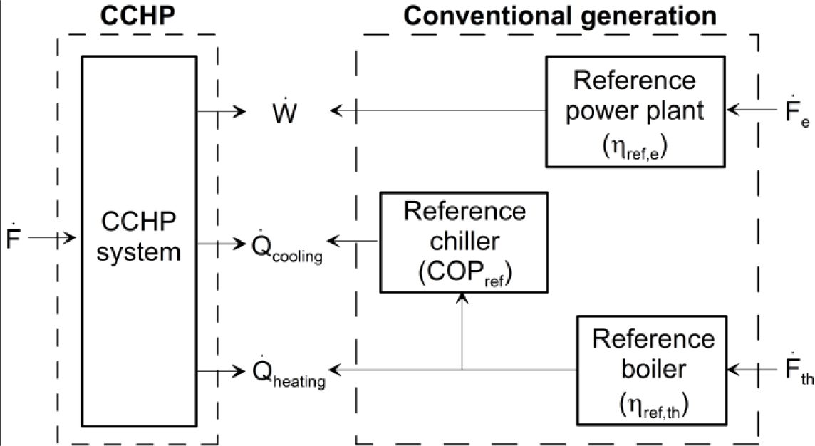
The primary energy savings ratio (PESR) is considered by several national policies to support efficient plants [31]. This parameter is used to compare multiproduct systems against reference plants with the same energy products. The primary energy savings are evaluated comparing the trigeneration system and a reference conventional scenario where the same type of biomass would be used in a power plant to generate electricity and a boiler and thermally driven chiller to generate heating and cooling. It can be expressed graphically, according to the framework depicted in Figure 2, and mathematically through Equation (9):
In Figure 2, the variables ηref,th and ηref,e are the harmonised efficiency reference values for separate production of electricity and heat (25% and 86% respectively [32]). On the other hand, due to the lack of a reference system for the cooling generation, a double effect absorption chiller (COP = 1.4), heat driven by the reference boiler, has been selected. The selection of a vapor-compression chiller consuming electricity from the reference power plant as a reference system would have entailed better results for the CCHP system, in terms of primary energy savings [4].
2.6. Life Cycle Assessment (LCA)
The environmental performance was evaluated through life cycle assessment tools. LCAs were undertaken considering the ISO 14040 standards [33,34] and the methodological issues regarding energy systems, and were performed using the SimaPro 7.3 software package [35] and the Ecoinvent database [36]. The environmental interventions were categorized and weighted according to the Eco-Indicator 99 [37] impact evaluation method, which is the more restrictive according to the results obtained in previous works [10].
The following life cycle stages of the different subsystems (see Figure 2) involved in the analysis were taken into account. The life cycle inventory considers the wood procurement, the wood chip production requirements, their transport to the plant, the combustion process, the ash disposal and finally the building and dismantling of all the subsystems involved (boiler, power plant, ORC, cooling unit) [38,39].
For every system assessed, one hour of operation was defined as the functional unit. The impact results were obtained by weighting every category considered by the evaluation method and the difference between CCHP and conventional generation impacts was estimated as:
3. Results and Discussion
3.1. Systematic Optimization Results
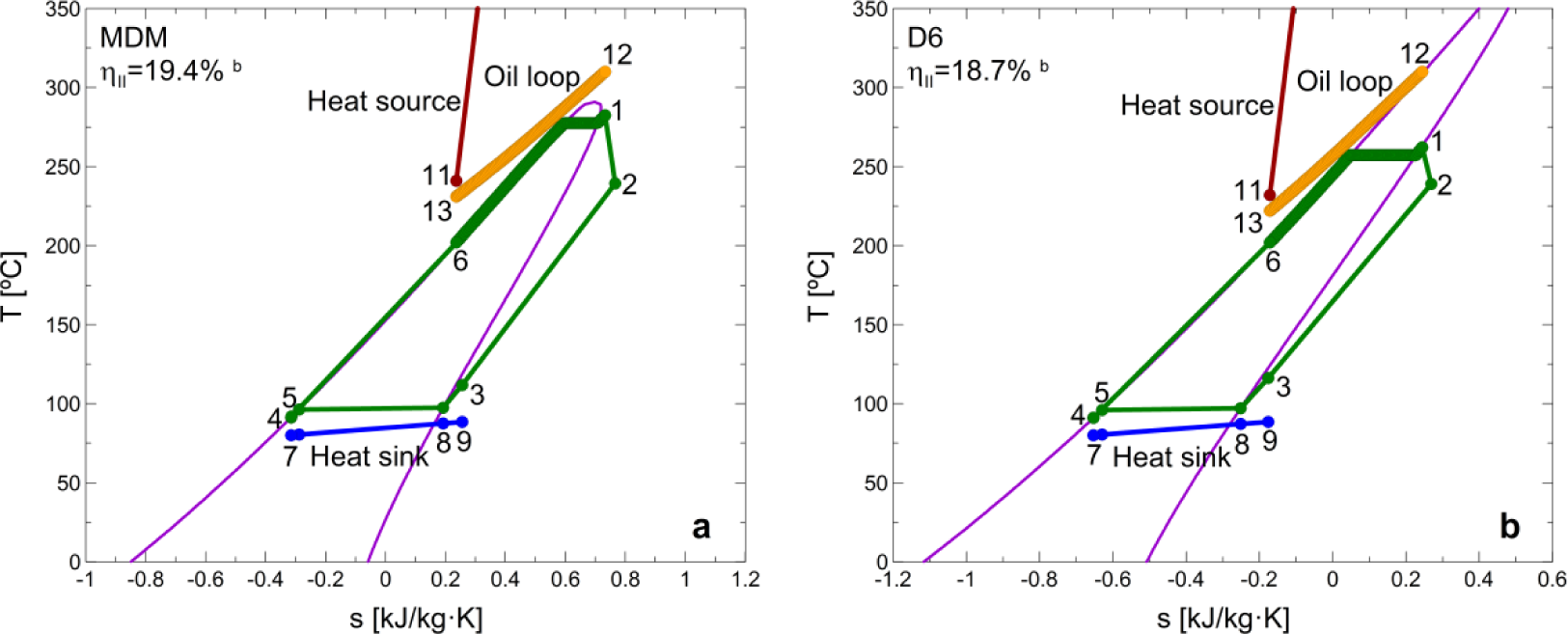
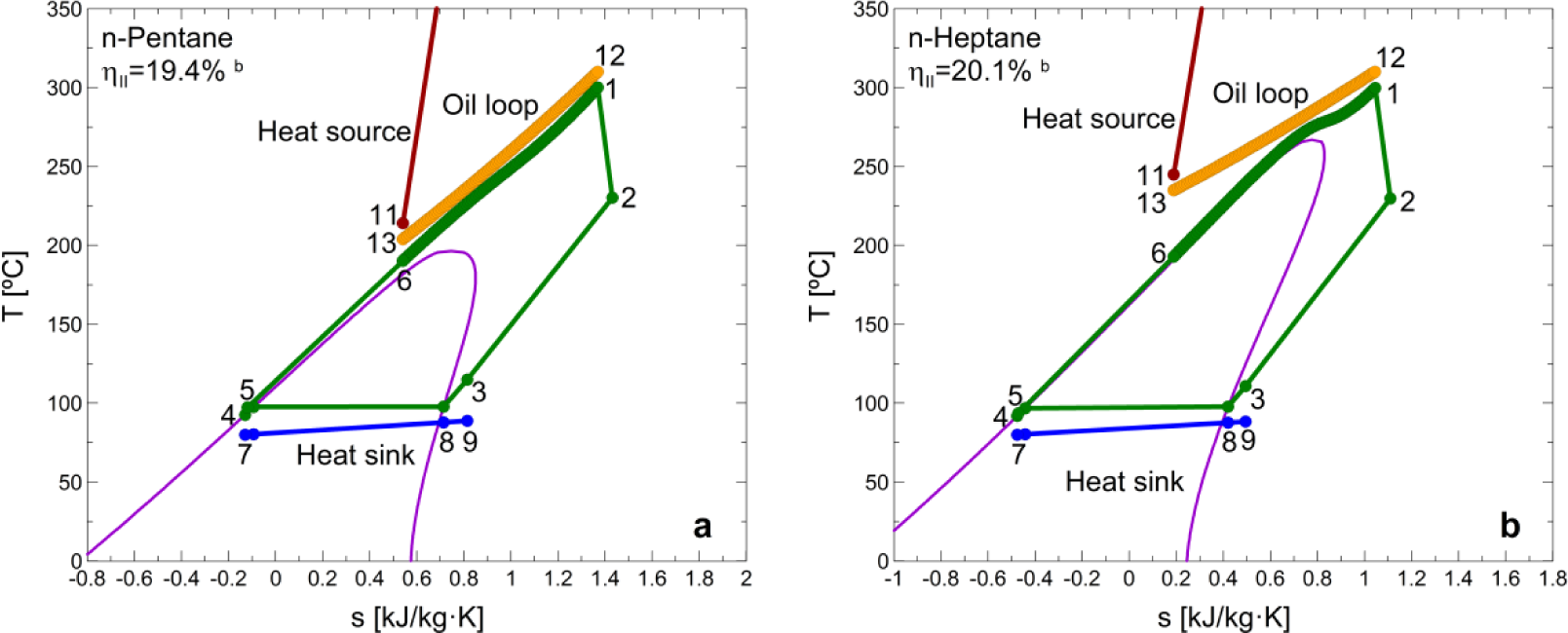
In this section, general statements are extracted regarding the optimization results, complemented with the practical features of such an optimization, which includes both thermodynamic and practical aspects. Table 2 shows the optimal ORC parameters that maximize the second law efficiency, and the corresponding indicators, for each considered working fluid and cooling unit. Furthermore, the optimal cycles are shown in Figures 3 and 5 (the integrations with adsorption chiller are not represented due to the graphical similarity, at the current scale, of their T-s diagrams in comparison with the integrations with absorption units). The optimal parameters do not vary depending on the heating or cooling rate generated by the CCHP system. However, the performance results of the system (ηII, PESR and ΔIMPACT) do indeed vary according to the specific distribution of the heat generated in the ORC condenser (cooling or heating purposes). The performance results shown in Table 2 are referred to the specific case when 50% of the heat in the condenser is used to directly supply a heat demand and the rest is assigned to drive the cooling unit. A more detailed study of the effect of this heat distribution (study of the plant performance at different nominal loads) is evaluated in Section 3.3.
The differences in the second law efficiency of the trigeneration plants integrated by different cooling technologies are mainly due to the different heat sink temperatures of the ORCs. For instance, in the case of the integration of adsorption units the lower driving temperature of then chiller enables a better performance of the cycle. However, the exergy flow rate of the heat generated in the ORC condenser is lower due to its lower temperature.
The systematic optimization procedure tends to match the T-s profiles of the heat source and the working fluid in the evaporator, minimizing the irreversibilities in the evaporator, and hence in the cycle. This is the reason why the optimal exhaust temperature of the heat source in the evaporator varies from one fluid to another: to achieve a better match between the two profiles. Hence, the optimization leads to a similarity in the heat capacity flow rates of the fluids in the evaporator [15].
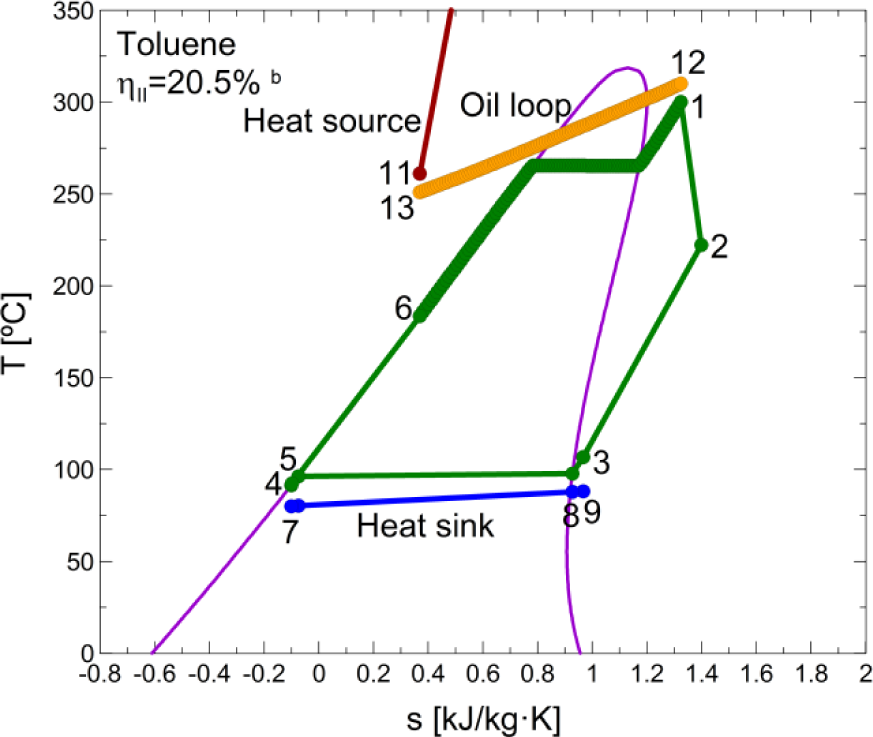
The optimization procedure leads to a subcritical cycle for MDM, D6 and toluene. The latter shows the best second law efficiency performance (Figure 5). In the case of n-pentane and n-heptane, the optimization leads to a transcritical cycle and the second-law efficiency achieved with this fluid is similar to the ones achieved by MDM and toluene, respectively. Despite the general guideline related to the better adaptation of higher critical-temperature fluids to higher temperature heat sources, this is not fulfilled in the case of D6 and n-heptane.
When comparing working fluids it is also very important to consider their practical impact on the system size and architecture, which avoids to recommend working fluids unsuitable for the studied application, e.g., due to a too low density or too high expansion ratio [9]. As a general rule, the very low fluid density of high temperature working fluids entails high VC and SP values which oversize the cycle components. This is supported by the results depicted in Table 2, where n-pentane shows more adequate values for the two expander parameters considered. The very low values of size parameter SP for n-pentane, n-heptane and toluene implies small-scale, high speed rotation turbine wheels, while MDM and D6 yield more practical dimensions and rotating speeds. Considering the ORC expander as a volumetric type, the values of the VC parameter obtained for the optimal cycles show that this type of expander is better-adapted to lower critical-temperature fluids, according to the typical range characteristic of this type of machine (see Section 2.3). Therefore, in the practical design of the ORC, a tradeoff ruled by thermo-economic aspects [9] will generally appear between the cycle thermodynamic performance and component size.
The constant pinch point assumption logically leads to an increase in the required heat exchanger conductance. A variable pinch point has not been considered due to the high discrepancies between the experimental heat transfer correlations in the literature [40]. Besides, this assessment is out of the scope of this work. However, it is important to note that, in practice, a trade off might be found between the pinch point and heat exchanger size. From the practical point of view of the heat exchangers, the toluene ORC will be more adequate due to the lower requirements of total heat transfer conductance of the cycle.
The selection of the right superheating degree ultimately results in the minimization of exergy destruction in the heat source heat exchanger. A thermodynamic model of the cycle is therefore needed, as proposed in this work. Table 2 shows that, in the particular case of transcritical cycles, the optimization leads to the highest possible superheating, constrained by the pinch point limitation. In the case of siloxanes (MDM and D6) the optimization leads to the minimum pinch point (5 K).
The use of a recuperator allows a better match of the two T-s profiles in the evaporator (hot fluid and working fluid flows), reducing the temperature difference between the source and the working fluid along the heat exchanger, thus reducing the irreversibilities in the evaporator [15]. In addition, the use of a recuperator is justified in this application due to the extraordinary high temperature at the expander outlet. This has been verified according to the results shown in Table 3.
3.2. Influence of the ORC Heat Driving Temperature and Constraints Associated
The main way to improve the performance of the proposed system (boiler + ORC + chiller) is to rise the heat driving temperature of the ORC, which is limited by the thermal stability of the heat transfer fluid and by the presence of the heat transfer loop itself. Thereby, this section presents the effect of both increasing this temperature and avoiding the heat transfer loop, with the aim of studying possible improvements in the system to increase the plant performance while considering the main limitations of such improvements. For this purpose, the plant integrated with a toluene recuperative cycle and an absorption chiller was selected.
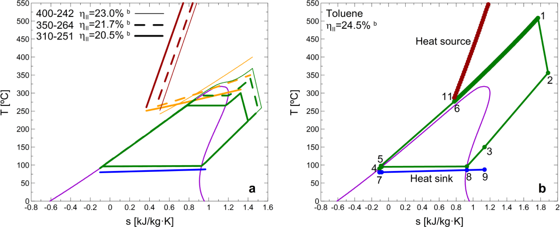
Firstly, the influence of the heat source temperature on the second law efficiency was studied, and the results are shown in Figure 6a. The rise in the thermal oil temperature at the inlet of the evaporator implies the expected increase in the second law efficiency of the plant thereby recommending the use of a heat transfer fluid able to work in a higher temperature range. Most of the thermal oils used in real applications are not able to work at such high temperatures [14], however, further developments and use of different heat transfer fluids will increase the plant’s performance. From the results shown in Figure 6a, every 50 °C heat source temperature increase can be quantified with an approximate second law efficiency increase of 6%
Secondly, another aspect worth considering in the practical design of this type of plants is the future development of direct fired units (avoiding the heat transfer loop). The results of the optimal direct fired ORC is shown in Figure 6b through its temperature-entropy diagram, and the numbers depicted correspond to the same streams shown in Figure 1, avoiding the heat transfer loop between the biomass boiler and the evaporator: the working fluid (6) is directly conveyed to the boiler to generate vapor (1). The efficiency increase linked to the heat transfer loop elimination can be quantified with a 20% increment (from 20.5% to 24.5%) in the plant’s second law efficiency. Technical parameters of the optimal ORC are shown in Table 4.
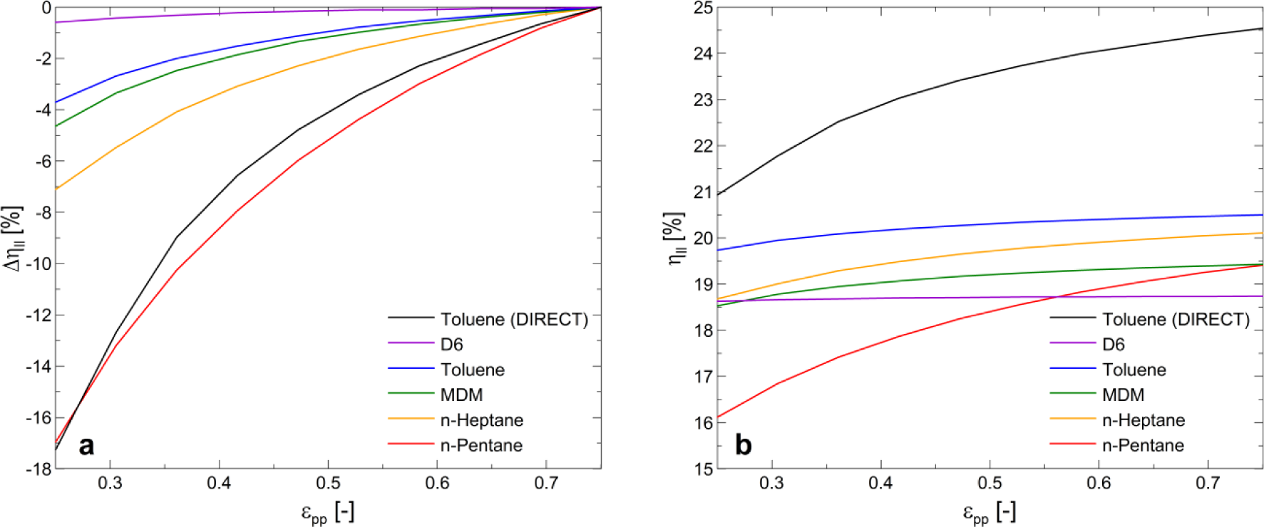
The transcritical operation of the ORC entails the improvement in the second law efficiency and also the downsizing of the cycle components due to the higher densities in the high pressure line. This is supported by the lower heat transfer conductance values shown in Table 4 in comparison to the ones shown in Table 2. However, two main disadvantages also appear in transcritical operation: it results in increased volume ratios, requiring more stages in the expansion process, and it leads to very high pressure levels, requiring tremendous pumping expenditures. The latter drawback might be prohibitive for some applications, since one of the advantages of ORC systems is the lower pressure in the evaporator with respect to conventional steam cycles. Hence, one important constraint linked to the transcritical operation is the feed pump isentropic efficiency. As shown in Figure 7, the decrease in the pump efficiency implies a significant decrease the more transcritical the cycle is.
3.3. Operation Performance of the Optimal BCCHP System at Different Nominal Loads
The indicator results shown in Table 2 and Figures 3 and 6 correspond to the specific case when 50% of the heat in the ORC condenser is used directly to supply a heat demand and the rest is assigned to drive the cooling unit. However, the variation in the nominal heating and cooling loads of the CCHP plant has an important influence on the second law efficiency, energy and environmental performance.
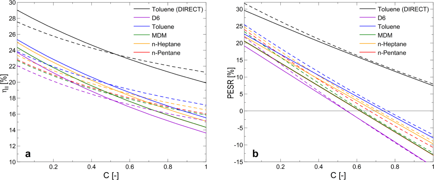
Figure 8 shows the second law efficiency (a) and primary energy savings (b) variations through the so-called cooling factor (C) [4], specifically defined to facilitate this analysis. This parameter is defined as:
According to Equation 11, low C values represent high production of heating in comparison to cooling.
Two different opposed effects influence the plant performance according to the cooling unit type selection. The higher COP of the cooling unit is the better plant performance could be achieved. However, higher COPs imply higher driving temperatures which entail a rise in the condensing pressure of the ORC (lowering its electric efficiency) and in consequence the plant performance
In the case of the second law efficiency (Figure 8a), the high COP of the absorption units is more important for the plant performance than the higher electric efficiency of the ORCs integrated with adsorption units, at low C values. However, the rise of C implies a decrease in ηII and at high C values the performance of the plant is more influenced by the higher power achieved with the plant integrations where the heat sink temperature of the ORC is lower, despite the lower COP of the unit. In addition, the second law efficiency is affected by the different temperatures of the heating depending on the integration of ORC with absorption or adsorption units.
In the case of the PESR (Figure 8b), the decrease in the heat sink temperature of the ORC linked to the lower heat driving temperature of the adsorption chiller leads to an electric efficiency increase in the ORC, which is responsible of achieving primary energy savings at low C values. However, at higher C values the higher coefficients of performance of absorption units (more similar to the reference) are responsible for the narrowing of the difference between both cooling technologies.
The C parameter was also used to evaluate the relation between the generated heating and cooling loads to achieve an environmental impact reduction in comparison to conventional generation. Figure 9 shows the environmental performance results for the toluene recuperative ORC, which is the most promising cycle according the results obtained in the previous analysis.
The LCA results of an energy system are strongly linked to the system operation and hence to the plant primary energy consumption. Despite the possible subjectivity associated to the LCA methodology, considering the different life cycle stages of the plant entails a difference in the ΔIMPACT curve with respect to the PESR curve.
In general, every trigeneration system integrated with the optimal ORC can achieve primary energy savings and environmental impact reduction in comparison to conventional generation. However, the increase of the amount of heat destined to the cooling generation decreases the trigeneration plant performance both in terms of energy savings and environmental impact. Consequently, there is a limit to the energy and environmental feasibility of the plant, which can be computed in terms of the relation between the heating and cooling productions (C). On the one hand, the energy feasibility has an approximate C limit value in the range of 0.55 (D6) and 0.75 (toluene). On the other hand, the environmental feasibility of the plants integrated by adsorption units is limited to an approximate C value of 0.6. In addition, the performance improvement achieved by the elimination of the heat transfer loop (direct fired ORC units) entails achieving primary energy and environmental impact savings for every cooling and heating load.
The CCHP plants exclusively generating power and cooling (C = 1) are not feasible in terms of the PESR, i.e., they have a worse performance than the reference plant when only generating power and cooling, except for the case of direct fired units. This is due to the high COP of the reference chiller in comparison to the average considered by the trigeneration plant. The consideration of a different comparison framework (Section 2.5) will positively affect these results for the CCHP system.
From the energy and environmental performance point of view, the best systems are the ones where the cooling is generated in an adsorption unit. However, despite of its slightly lower performance, the integrations of absorption units can supply higher temperature heating demands, while the integrations of adsorption units would be limited to lower temperature demands such as radiant floor heating and domestic hot water demands.
In summary, the comparison between the energy and environmental impact results (Figures 8 and 9) show that the performance of the plant does indeed accomplish the benefits of multi-generation systems.
4. Conclusions
The main objective of this work was to study the optimal design of an ORC integrated in a small-scale CCHP system based on biomass combustion. The analysis carried out includes the working fluid selection, the expander inlet pressure and temperature, the superheating degree, the operation mode (subcritical or transcritical) and the presence of a recuperator, considering the constraints of the main components of the ORC (heat exchangers, expander and feed pump). In addition, the optimal ORC integrated with a biomass boiler and the different thermally driven units available in the market were assessed to evaluate their adequacy to supply different heating and cooling demands from an energy savings and environmental perspective.
A thermodynamic optimization model of the trigeneration system was used to compute both subcritical and transcritical operation of the ORC. This model has proven its effectiveness in the task of extracting general design guidelines for the ORC, despite the lack of proper heat transfer and pressure drop correlations, mainly because of the high discrepancies between the experimental heat transfer correlations in the literature.
The different working fluid ORCs analyzed in this work show a good thermodynamic performance when they are integrated in a CCHP plant with a biomass boiler and a thermally driven cooling technology. However, under the conditions analyzed in this study, toluene shows a slightly better thermodynamic performance. The recuperative toluene ORC is not well adapted to the volumetric expander (according to the VC parameter) so it should be developed with a turbine type expander. If the ORC unit is developed from a volumetric type expander, the optimal cycle is the recuperative n-pentane one, whose main limitations are the lower amount of cooling in comparison to the heating that the plant can supply achieving energy and environmental savings, and the high heat transfer conductances due to the transcritical operation of the optimal cycle. The integration of a MDM recuperative ORC in a trigeneration plant is also feasible and it could be developed with a turbine type expander with more practical dimensions and rotating speeds than the rest of the fluids. n-Heptane shows a good thermodynamic performance but it is also limited to a development through a turbine type expander. Finally, the recuperative D6 ORC implies the poorest thermodynamic performance and also shows technical constraints regarding the volumetric expander and heat transfer conductances.
Regarding the cooling technology, the plants integrated by adsorption units entail a slightly better performance than absorption units, but the decision of using absorption or adsorption chillers should also be based on the heat demand temperature of the corresponding application. Further developments of direct fired ORC units could represent a 20% improvement in the plant performance if the limitations of transcritical operation are avoided.
Acknowledgments
This work is financially supported by the Spanish Ministry of Economy and Competitiveness, On-3-Bioterm project (“Biomass use from energy crops for power and heating generation in the residential and tertiary sectors”), ref. IPT-120000-2010-009.
Author’s Contributions
D. Maraver and J. Royo conceived and lead the elaboration of the paper through all the stages. D. Maraver and S. Quoilin developed the thermodynamic model, with some input from J. Royo. All authors cooperated in the analysis and interpretation of data, writing and revision of the paper.
Conflicts of Interests
The authors declare no conflict of interest.
| Nomenclature | |
|---|---|
| AU | Heat transfer conductance (kW/K) |
| C | Cooling factor (−) |
| COP | Coefficient of performance (−) |
| D | Diameter (m) |
| Ds | Specific diameter (−) |
| Ė | Exergy flow rate (kW) |
| h | Specific enthalpy (kJ/kg·K) |
| ṁ | Mass flow rate (kg/s) |
| N | Number of discretization nodes (−) |
| P | Pressure (kPa) |
| PESR | Primary energy savings Ratio (%) |
| pinch | Pinch point value (K) |
| Q̇ | Heat rate (kW) |
| SP | Size Parameter (cm) |
| T | Temperature (°C) |
| V̇ | Volumetric flow rate (m3/s) |
| v | Specific volume (m3/kg) |
| VC | Volume coefficient (m3/kJ) |
| Ẇ | Mechanical or electrical power (kW) |
| Greek letters | |
|---|---|
| Δ | Difference (−) |
| η | Efficiency (%) |
| Subscripts and superscripts | |
|---|---|
| 0 | Reference conditions |
| e | Electrical |
| ev | Evaporator |
| ex | Exhaust |
| exp | Expander |
| II | Second law |
| pp | Pump |
| ref | Reference |
| s | Isentropic |
| su | Supply |
| th | Thermal |
| Abbreviations | |
|---|---|
| ABS | Absorption Cooling |
| ADS | Adsorption Cooling |
| CHP | Combined Heating and Power |
| CCHP | Combined Cooling, Heating and Power |
| D6 | Dodecamethylcyclohexasiloxane |
| IHE | Internal Heat Exchanger |
| MDM | Octamethyltrisiloxane |
| ORC | Organic Rankine Cycle |
References
- Wu, D.W.; Wang, R.Z. Combined cooling, heating and power: A review. Prog. Energy Combust. Sci 2006, 32, 459–495. [Google Scholar]
- Xu, J.; Sui, J.; Li, B.; Yang, M. Research, development and the prospect of combined cooling, heating, and power systems. Energy 2010, 35, 4361–4367. [Google Scholar]
- Maraver, D.; Rezeau, A.; Sebastián, F.; Royo, J. Thermodynamic optimization of a trigeneration system based on biomass combustion, Proceedings of the XVII European Biomass Conference & Exhibition, Hamburg, Germany, 29 June–3 July 2009.
- Maraver, D.; Sin, A.; Royo, J.; Sebastián, F. Assessment of CCHP systems based on biomass combustion for small-scale applications through a review of the technology and analysis of energy efficiency parameters. Appl. Energy 2013, 102, 1303–1313. [Google Scholar]
- Angrisani, G.; Roselli, C.; Sasso, M. Distributed microtrigeneration systems. Prog. Energy Combust 2012, 38, 502–521. [Google Scholar]
- Al-Sulaiman, F.A.; Dincer, I.; Hamdullahpur, F. Energy and exergy analyses of a biomass trigeneration system using an organic rankine cycle. Energy 2012, 45, 975–985. [Google Scholar]
- Al-Sulaiman, F.A.; Hamdullahpur, F.; Dincer, I. Greenhouse gas emission and exergy assessments of an integrated organic Rankine cycle with a biomass combustor for combined cooling, heating and power production. Appl. Therm. Eng 2011, 31, 439–446. [Google Scholar]
- Huang, Y.; Wang, Y.D.; Rezvani, S.; McIlveen-Wright, D.R.; Anderson, M.; Mondol, J.; Zacharopolous, A.; Hewitt, N.J. A techno-economic assessment of biomass fuelled trigeneration system integrated with organic Rankine cycle. Appl. Therm. Eng 2013, 53, 325–331. [Google Scholar]
- Quoilin, S.; Declaye, S.; Tchanche, B.F.; Lemort, V. Thermo-economic optimization of waste heat recovery organic Rankine cycles. Appl. Therm. Eng 2011, 31, 2885–2893. [Google Scholar]
- Maraver, D.; Sin, A.; Sebastián, F.; Royo, J. Environmental assessment of CCHP (combined cooling heating and power) systems based on biomass combustion in comparison to conventional generation. Energy 2013, 57, 17–23. [Google Scholar]
- European technology platform on renewable heating and cooling. Strategic research priorities for biomass technology. Available online: http://www.rhc-platform.org/fileadmin/Publications/Biomass_SRA.pdf (accessed on 27 February 2014).
- Blanco, J.M.; Peña, F. Increase in the boiler’s performance in terms of the acid dew point temperature: Environmental advantages of replacing fuels. Appl. Therm. Eng 2008, 28, 777–784. [Google Scholar]
- Drescher, U.; Brüggemann, D. Fluid selection for the organic rankine cycle (ORC) in biomass power and heat plants. Appl. Therm. Eng 2007, 27, 223–228. [Google Scholar]
- Northern Innovation, Technical Investigation into Thermal Oil Technology (Project no. 1555); Xiron Patrascu Marius: Belfast, Northern Ireland, 2010.
- Maraver, D.; Royo, J.; Lemort, V.; Quoilin, S. Systematic optimization of subcritical and transcritical organic Rankine cycles (ORCs) constrained by technical parameters in multiple applications. Appl. Energy 2014, 117, 11–29. [Google Scholar]
- Klein, S.A. Engineering Equation Solver; F-chart Software: Middleton, WI, USA, 2012. [Google Scholar]
- Bell, I.H.; Wronski, J.; Quoilin, S.; Lemort, V. Pure and pseudo-pure fluid thermophysical property evaluation and the open-source thermophysical property library Coolprop. Ind. Eng. Chem. Res 2014, 53, 2498–2508. [Google Scholar]
- Lakew, A.A.; Bolland, O. Working fluids for low-temperature heat source. Appl. Therm. Eng 2010, 30, 1262–1268. [Google Scholar]
- Tchanche, B.F.; Papadakis, G.; Lambrinos, G.; Frangoudakis, A. Fluid selection for a low-temperature solar organic Rankine cycle. Appl. Therm. Eng 2009, 29, 2468–2476. [Google Scholar]
- Stepanov, V.S. Chemical energies and exergies of fuels. Energy 1995, 20, 235–242. [Google Scholar]
- Angelino, G.; Invernizzi, C.; Macchi, E. Organic working fluid optimization for space power cycles. In Modern Research Topics in Aerospace Propulsion; Angelino, G., de Luca, L., Sirignano, W.A., Eds.; Springer-Verlag: New York, NY, USA, 1991; pp. 297–324. [Google Scholar]
- Macchi, E.; Perdichizzi, A. Efficiency prediction for axial-flow turbines operating with nonconventional fluids. J. Eng. Gas Turbines Power 1981, 103, 718–724. [Google Scholar]
- Quoilin, S. Sustainable Energy Conversion through the Use of Organic Rankine Cycles for Waste Heat Recovery and Solar Applications; University of Liège: Liège, Belgium, 2011. [Google Scholar]
- Jones, D.R.; Perttunen, C.D.; Stuckman, B.E. Lipschitzian optimization without the lipschitz constant. J. Optim. Theory Appl 1993, 79, 157–181. [Google Scholar]
- Quoilin, S.; Lemort, V.; Lebrun, J. Experimental study and modeling of an organic Rankine cycle using scroll expander. Appl. Energy 2010, 87, 1260–1268. [Google Scholar]
- Branchini, L.; de Pascale, A.; Peretto, A. Systematic comparison of ORC configurations by means of comprehensive performance indexes. Appl. Therm. Eng 2013, 61, 129–140. [Google Scholar]
- Declaye, S.; Quoilin, S.; Guillaume, L.; Lemort, V. Experimental study on an open-drive scroll expander integrated into an ORC (organic Rankine cycle) system with R245fa as working fluid. Energy 2013, 55, 173–183. [Google Scholar]
- Sun, J.; Li, W. Operation optimization of an organic Rankine cycle (ORC) heat recovery power plant. Appl. Therm. Eng 2011, 31, 2032–2041. [Google Scholar]
- Brasz, L.J.; Bilbow, W.M. Ranking of working fluids for organic rankine cycle applications, Proceedings of the International Refrigeration and Air Conditioning Conference, Purdue, IN, USA, 12–15 July 2004.
- Shengjun, Z.; Huaixin, W.; Tao, G. Performance comparison and parametric optimization of subcritical organic Rankine cycle (ORC) and transcritical power cycle system for low-temperature geothermal power generation. Appl. Energy 2011, 88, 2740–2754. [Google Scholar]
- Cardona, E.; Piacentino, A. A methodology for sizing a trigeneration plant in mediterranean areas. Appl. Therm. Eng 2003, 23, 1665–1680. [Google Scholar]
- Commission, E. Commission decision of 19 december 2011 establishing harmonised efficiency reference values for separate production of electricity and heat in application of directive 2004/8/EC of the European Parliament and of the Council. Off. J. Eur. Union 2011, 343, 91–96. [Google Scholar]
- ISO, ISO 14040: Environmental Management—Life Cycle Assessment—Principles and Framework; ISO: Genève, Switzerland, 2006.
- ISO, ISO 14044: Environmental Management—Life Cycle Assessment—Requirements and Guidelines; ISO: Genève, Switzerland, 2006.
- Pré consultants. Simapro 7.3: Life cycle assessment software, 2012. Availabel online: http://www.pre-sustainability.com/simapro (accessed on 29 April 2014).
- Frischknecht, R.; Rebitzer, G. The ecoinvent database system: A comprehensive web-based lca database. J. Clean. Prod 2005, 13, 1337–1343. [Google Scholar]
- Goedkoop, M.; Spriensma, R. The Eco-indicator 99: A Damage Oriented Method for Life Cycle Assessment, Methodology Report, 2nd ed; pré consultants: Amersfoort, the Netherlands; Volume 4, Available online: http://www.Pre.Nl/eco-indicator99/ (accessed on 25 April 2014).
- Bauer, C. Holzenergie. In Sachbilanzen von Energiesystemen: Grundlagen für den Ökologischen Vergleich von Energiesystemen und den Einbezug von Energiesystemen in Ökobilanzen für die Schweiz; Dones, R., Ed.; Swiss Centre for Life Cycle Inventories: Dübendorf, Switzerland, 2007. [Google Scholar]
- Primas, A. Life Cycle Inventories of New CHP Systems. Final Report Ecoinvent Data v2.0, No. 20; Swiss Centre for Life Cycle Inventories: Dübendorf, Switzerland, 2007. [Google Scholar]
- García-Cascales, J.R.; Vera-García, F.; Corberán-Salvador, J.M.; Gonzálvez-Maciá, J. Assessment of boiling and condensation heat transfer correlations in the modelling of plate heat exchangers. Int. J. Refrig 2007, 30, 1029–1041. [Google Scholar]


| Cooling technology | Heat driving circuit temperature, °C
| COP, − | Cooling temperature, °C
| ||
|---|---|---|---|---|---|
| In | Out | In | Out | ||
| Absorption (ABS) | 90 | 80 | 0.7 | 12 | 7 |
| Adsorption (ADS) | 70 | 60 | 0.6 | 12 | 7 |
| Technical data | Indicators | |||||||||||
|---|---|---|---|---|---|---|---|---|---|---|---|---|
| Fluid | Cooling technology | Heat source loop, °C | ΔTex,ev, K | Psu.ev, kPa | AUTOTAL, kW/Ka | SP, cm | VC, m3/kJ | ηI, %b | ηII, %b | PESR, %b | ||
| In | Out | |||||||||||
| n-Pentane | ABS | 310 | 204 | 103.6 | 6.64×10³ | 148.2 | 2.3 | 1.1 × 10⁻³ | 68.1 | 19.4 | 7.0 | |
| ADS | 196 | 103.6 | 6.62×10³ | 140.9 | 2.7 | 1.4×10⁻³ | 65.3 | 19.6 | 10.1 | |||
| n-Heptane | ABS | 235 | 32.7 | 3.20×10³ | 108.4 | 4.5 | 4.2×10⁻³ | 68.2 | 20.1 | 9.0 | ||
| ADS | 201 | 23.8 | 3.41×10³ | 107.8 | 5.8 | 6.4×10⁻³ | 65.4 | 20.0 | 11.3 | |||
| MDM | ABS | 231 | 5.0 | 1.16×10³ | 109.8 | 10.7 | 1.8×10⁻² | 68.1 | 19.4 | 7.0 | ||
| ADS | 211 | 5.0 | 1.04×10³ | 109.1 | 14.6 | 3.3×10⁻² | 65.1 | 19.2 | 9.0 | |||
| Toluene | ABS | 251 | 34.9 | 2.09×10³ | 91.3 | 5.1 | 5.7×10⁻³ | 68.2 | 20.5 | 10.1 | ||
| ADS | 245 | 37.1 | 2.02×10³ | 90.5 | 6.4 | 8.9×10⁻³ | 65.4 | 20.4 | 12.4 | |||
| D6 | ABS | 222 | 5.0 | 1.33×10² | 106.5 | 50.5 | 3.8×10⁻¹ | 67.9 | 18.7 | 4.8 | ||
| ADS | 222 | 5.0 | 1.45×10² | 98.6 | 80.9 | 9.8×10⁻¹ | 64.9 | 18.5 | 6.8 | |||
aAUTOTAL = AUev + AUcd + AUIHE.bThese values correspond to the case when 50% of the heat in the condenser is used to directly supply a heat demand and the rest is assigned to drive the cooling unit.
| Heat sink profile | n-Pentane | n-Heptane | MDM | Toluene | D6 |
|---|---|---|---|---|---|
| ABS | 19.2% | 19.5% | 23.7% | 14.7% | 24.0% |
| ABSDE | 8.3% | 8.3% | 10.4% | 5.7% | 12.0% |
| ADS | 23.8% | 22.0% | 29.0% | 17.0% | 29.6% |
| Technical data | Indicators | |||||||
|---|---|---|---|---|---|---|---|---|
| Fluid | Cooling technology | ΔTex,ev, K | Psu.ev, kPa | AUTOTAL, kW/Ka | SP, cm | VC, m3/kJ | ηI, %b | ηII, %b |
| Toluene | ABS | 189.8 | 1.61×10⁴ | 54.6 | 4.2 | 3.8×10⁻³ | 68.9 | 24.5 |
| ADS | 191.7 | 1.75×10⁴ | 52.7 | 5.3 | 6.0×10⁻³ | 66.3 | 24.5 | |
© 2014 by the authors; licensee MDPI, Basel, Switzerland This article is an open access article distributed under the terms and conditions of the Creative Commons Attribution license (http://creativecommons.org/licenses/by/3.0/).
Share and Cite
Maraver, D.; Quoilin, S.; Royo, J. Optimization of Biomass-Fuelled Combined Cooling, Heating and Power (CCHP) Systems Integrated with Subcritical or Transcritical Organic Rankine Cycles (ORCs). Entropy 2014, 16, 2433-2453. https://doi.org/10.3390/e16052433
Maraver D, Quoilin S, Royo J. Optimization of Biomass-Fuelled Combined Cooling, Heating and Power (CCHP) Systems Integrated with Subcritical or Transcritical Organic Rankine Cycles (ORCs). Entropy. 2014; 16(5):2433-2453. https://doi.org/10.3390/e16052433
Chicago/Turabian StyleMaraver, Daniel, Sylvain Quoilin, and Javier Royo. 2014. "Optimization of Biomass-Fuelled Combined Cooling, Heating and Power (CCHP) Systems Integrated with Subcritical or Transcritical Organic Rankine Cycles (ORCs)" Entropy 16, no. 5: 2433-2453. https://doi.org/10.3390/e16052433
APA StyleMaraver, D., Quoilin, S., & Royo, J. (2014). Optimization of Biomass-Fuelled Combined Cooling, Heating and Power (CCHP) Systems Integrated with Subcritical or Transcritical Organic Rankine Cycles (ORCs). Entropy, 16(5), 2433-2453. https://doi.org/10.3390/e16052433