Review

Liquid Hydrogen Application for Aero-Engine More-Electrical System: Current Status, Challenges and Future Prospects

School of Energy and Power Engineering, Huazhong University of Science and Technology, Wuhan 430074, China
*
Author to whom correspondence should be addressed.
Submission received: 19 February 2025 / Revised: 16 March 2025 / Accepted: 19 March 2025 / Published: 21 March 2025
(This article belongs to the Special Issue Efficient Production, Storage and Transportation of Liquid Hydrogen)

Abstract

:
The integration of more-electric technologies into aero-engines has revolutionized their multi-power architectures, substantially improving system maintainability and operational reliability. This advancement has established more-electric systems as a cornerstone of modern aerospace electrification research. Concurrently, liquid hydrogen (LH2) emerges as a transformative solution for next-generation power generation systems, particularly in enabling the transition from 100 kW to megawatt-class propulsion systems. Beyond its superior energy density, LH2 demonstrates dual functionality in thermal management: it serves as both an efficient coolant for power electronics (e.g., controllers) and a cryogenic source for superconducting motor applications. This study systematically investigates the electrification pathway for LH2-fueled aero-engine multi-electric systems. First, we delineate the technical framework, elucidating its architectural characteristics and associated challenges. Subsequently, we conduct a comprehensive analysis of three critical subsystems including LH2 storage and delivery systems, cryogenic cooling systems for superconducting motors, and Thermal management systems for high-power electronics. Finally, we synthesize current research progress and propose strategic directions to accelerate the development of LH2-powered more-electric aero-engines, addressing both technical bottlenecks and future implementation scenarios.

1. Introduction

1.1. Carbon Neutrality Imperatives in Aviation

With the global aviation industry accelerating toward carbon neutrality objectives, liquid hydrogen (LH2) has become a strategically vital alternative to conventional aviation fuels, driven by its zero-carbon combustion characteristics and exceptional energy density [1,2]. The International Air Transport Association (IATA) has formalized this transition through its 2050 carbon reduction mandate, targeting a 50% decrease in sector-wide emissions, where LH2’s environmental advantages position it as an indispensable solution [3]. Technically, LH2’s mass-specific combustion enthalpy of 142 MJ/kg-2.8 times greater than aviation kerosene enables substantial fuel mass reduction while maintaining equivalent energy output, directly enhancing aircraft range and payload capacity through mass optimization [1].
The More-Electric Aircraft (MEA) concept, initially proposed in the late 20th century, has matured into a foundational framework for modern aviation electrification. By systematically replacing pneumatic and hydraulic systems with electrical architectures, MEA achieves measurable efficiency gains, particularly in secondary power systems where energy losses in traditional configurations often exceed 30% [4]. Contemporary implementations leverage advanced power electronics and adaptive energy management algorithms, demonstrating 12–18% fuel savings through optimized electrical load distribution—a critical advancement given the escalating environmental regulations [4]. These technological strides have elevated MEA from conceptual studies to operational deployments, with modern platforms exhibiting 15–22% improvements in thrust-to-weight ratios compared with conventional counterparts.
Next-generation combat aircraft impose unprecedented demands on propulsion systems, requiring integrated starter-generators capable of delivering over 10 MW power output while maintaining thrust-to-weight ratios exceeding 10:1. Conventional permanent magnet machines face fundamental limitations under these conditions, constrained by power density ceilings below 5 kW/kg and thermal management challenges at heat flux densities above 20 kW/cm3. LH2 addresses these barriers through its dual role as cryogenic coolant and energy carrier: its ultra-low boiling point (20.3 K at standard pressure) enables superconducting windings using MgB2/YBaCuO composites, being expected to achieve 50 kw/kg specific power and 99% efficiency while eliminating ohmic losses [5]. Concurrently, LH2’s high thermal conductivity (0.17 W/m·K at 20 K) permits direct cooling of power electronics, enhancing thermal stability by 60–75% compared to air-cooled systems [6].
Military applications particularly capitalize on LH2’s synergistic benefits. Recent prototype evaluations demonstrate 30–45 dB reductions in acoustic signatures for electrically driven subsystems, coupled with 25% decreases in infrared detectability—critical for high-altitude surveillance platforms [7]. Furthermore, LH2’s energy density advantages support continuous 500+ kW auxiliary power delivery, enabling extended mission durations without compromising stealth characteristics. These operational advantages, combined with a 63% mass reduction in power distribution systems through voltage standardization (28 VDC vs. 115 VAC), establish LH2 as the definitive energy vector for next-generation multirole combat aircraft [5,6,7].

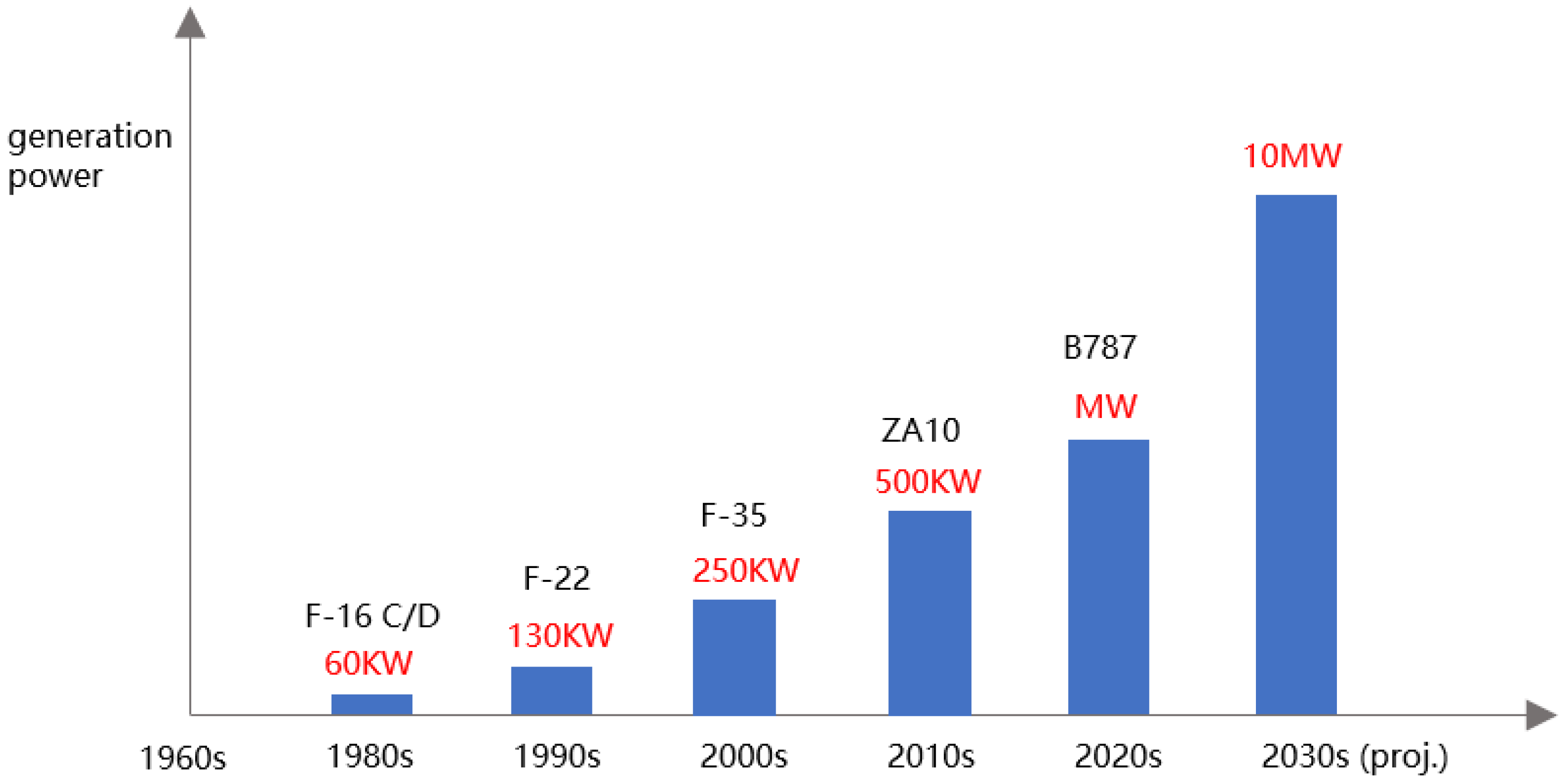
1.2. MEA Evolution Timeline

Some typical electric aircraft are listed in Figure 1.

2. Key Technologies for Liquid Hydrogen Application

Hydrogen energy technology has become a transformative force in aviation electrification, primarily manifesting in three interconnected domains. The first involves cryogenic storage and transportation systems, where LH2’s low boiling point (20.3 K at 1 atm) and high diffusivity (0.16 cm2/s at 293 K) necessitate advanced containment solutions employing multilayer vacuum insulation and composite membrane tank architectures to mitigate safety risks associated with hydrogen’s wide flammability range (4–75% vol). Second, hydrogen-electric propulsion systems are revolutionizing aircraft power generation through two distinct pathways: hydrogen-fueled gas turbines achieving 52–58% thermal efficiency through lean premixed combustion, and proton exchange membrane fuel cells delivering 45–60% electrical conversion efficiency at 80–95 °C operating temperatures. Third, LH2’s exceptional thermal properties (thermal conductivity: 0.17 W/m·K at 20 K) enable dual-function cooling systems that simultaneously maintain superconducting generators at 20–30 K operational temperatures and stabilize megawatt-class power electronics through phase-change heat transfer, extending component service life by 30–50 % compared to conventional air-cooled thermal management approaches.
Global aerospace innovation has entered a new phase of strategic competition, with the European Union’s Clean Aviation Joint Undertaking (CAJU) committing €700 million in its 2023 funding cycle to accelerate hydrogen aviation technologies. As detailed in Table 1, six flagship projects under the hydrogen-powered aircraft category focus on developing 30–40 bar combustion chambers for hydrogen turbines, integrating 2 MW fuel cell stacks with cryogenic cooling loops, and validating Type IV composite tanks capable of storing 150 kg/m3 liquid hydrogen with 0.8 g/L·kg mass efficiency. Parallel initiatives include the HEAVEN project’s turbine disk optimization for hydrogen combustion stability and FASTER-H2′s aerodynamic integration studies for blended-wing-body configurations using LH2 fuel distribution networks. The cross-cutting CONCERTO program addresses regulatory challenges through 78 safety validation protocols, establishing certification frameworks for hydrogen systems under EASA CS-25 standards [8] while maintaining compatibility with existing aviation infrastructure.
Clean Hydrogen Joint Undertaking (CHJU) continues to develop hydrogen fuel cell and hydrogen storage projects, as shown in Table 2.
Aerospace Technology Institute (ATI) was also heavily funding research projects on hydrogen turbine power and hydrogen electricity development, as shown in Table 3.

2.1. Liquid Hydrogen Storage, Transportation, and Refueling

Liquid hydrogen (LH2) storage systems must address dual challenges posed by cryogenic environments (20.3 K at 1 atm): minimizing boil-off losses below 0.8% per day through multilayer vacuum insulation while achieving mass-energy densities exceeding 6.8 kWh/kg via lightweight designs, all within pressure-bearing constraints (>5 bar operational pressure). Mital et al. [10] identified critical material requirements including hydrogen embrittlement resistance (<1.5% fracture strain), low thermal expansion coefficients (CTE <5 × 10⁻⁶/K), and permeability thresholds < 10−10 m2/s, with titanium-carbon fiber composites demonstrating 0.95 safety factors across 77–293 K thermal cycles [11]. European Clean Aviation initiatives exemplify technological advancements through three flagship projects: The H2ELIOS project developed integrated LH2 tanks achieving 0.82 g/L·kg mass efficiency, while the fLHYing tank program successfully validated 200 h continuous cryogenic operation (−253 °C) in unmanned aerial platforms. Concurrently, the COCOLIH2T project pioneered thermoplastic composite tanks enhancing structural strength by 40% with a 15% cost reduction [12].
Thermal management breakthroughs are evidenced by the ENABLEH2 project [13], which reduced heat leakage to 0.6 W/m2 through aluminum-carbon fiber shells integrated with 30-layer metallized polyester films in multilayer insulation (MLI), decreasing thermal penetration by 58%. Real-time monitoring using cryogenic heat flux meters revealed dynamic vacuum maintenance systems can limit daily evaporation to 0.3%, providing critical data for insulation optimization.
LH2 transportation infrastructure demands precision fluid handling systems. NASA’s IZEA program [14] established an integrated liquefaction-refueling system employing helium expansion refrigeration to reduce specific energy consumption to 12 kWh/kg, coupled with adaptive cryopump algorithms maintaining ±1.5% flow stability. The ATI-led LH2GT project [15] advanced cryogenic mass flow meters with 80 ms response times (50% improvement over conventional units) and 0.2% accuracy under 0.5–5 Hz pressure pulsations, enabling robust fuel delivery for megawatt-class hydrogen turbines. Experimental validation via cryogenic flow test benches confirmed operational reliability across 2.5 MPa working pressures.
A pivotal development emerged in March 2023 through Spain’s ITP Aero consortium [1], launching a four-pillar research initiative: (1) Phase-change systems achieving 98% LH2-to-gas conversion efficiency, (2) Integration of 3 MW fuel cell propulsion architectures, (3) Combustion stability analysis for hydrogen flames, and (4) Retrofit solutions enabling hybrid natural gas-hydrogen combustion in legacy engines, demonstrating NOx emissions below 5 g/kg fuel at cruise conditions. This comprehensive program establishes critical pathways for full hydrogen propulsion adoption in next-generation aviation.

2.2. Liquid Hydrogen-Fueled Electric Propulsion Technologies

Current liquid hydrogen propulsion architectures primarily evolve through two complementary pathways: hydrogen turbo-electric systems and fuel cell electric propulsion, with hybrid configurations emerging as a synergistic development frontier.
The hydrogen turbo-electric concept employs a turbine-generator-motor cascade (Figure 2), where combustion-driven turbines power superconducting generators that deliver >98% efficient electrical conversion [16], subsequently energizing distributed electric fans. Netherlands Aerospace Centre (NLR) studies demonstrate that this architecture reduces specific fuel consumption by 9–12% compared to conventional turbofans through three mechanisms: (1) Decoupling turbine operation from thrust requirements via electrical energy storage buffers, (2) Enabling variable-speed fan optimization across flight regimes, and (3) Recovering 35–40% waste heat through regenerative Brayton cycles [17]. Recent prototypes achieve 8.2 kN/MW specific thrust with 82 dB noise reduction at 50 m sideline distances.
Complementing this approach, proton exchange membrane fuel cells (PEMFCs) enable true zero-emission propulsion through direct electrochemical conversion (Figure 3), exhibiting 45–60% stack efficiency at 1.5–3.0 A/m2 current densities. And it refuels quickly, similar to oil fuel refueling. Modern aviation-grade PEMFC systems achieve 1.8 kW/kg specific power with 8000 h durability, though practical implementation faces two key constraints: (1) System-level energy density (800–1200 Wh/kg) remains 28–35% below Jet A-1 equivalents, limiting maximum ranges to <1500 km for regional aircraft, and (2) Cryogenic hydrogen storage reduces payload capacity by 12–18% compared to conventional fuel systems [16].
Emerging hybrid configurations aim to transcend these limitations through intelligent power blending. The EU’s HYCARUS project demonstrates a 22% range extension in 70-seat regional jets by combining 4 MW turbogenerators with 1.2 MW fuel cells, utilizing dynamic power allocation algorithms that optimize hydrogen consumption across climb/cruise/descent phases. Such systems maintain operational flexibility while achieving 98 g CO2/pkm emission levels-76% below current ICAO CAEP/10 standards [18].

2.3. Cryogenic Hydrogen Cooling Technology

Aero-engine electric propulsion systems face critical thermal management challenges due to their exceptional power densities (>20 kW/kg) combined with extreme operational environments characterized by low atmospheric pressure (0.2–0.5 bar) and elevated ambient temperatures (400–600 K). Conventional air-cooling methods prove inadequate with convective heat transfer coefficients below 50 W/m2K, while oil-cooling introduces parasitic losses exceeding 15% through rotor churning effects at >10,000 rpm. Emerging solutions span advanced potting materials with thermal conductivities up to 25 W/mK [19,20,21,22,23], oscillating heat pipes achieving 800–1200 W/cm2 heat fluxes [24,25,26], and phase-change composites storing 300–400 kJ/kg latent heat [27,28]. For megawatt-class superconducting systems, liquid hydrogen (LH2) cooling presents transformative potential through its dual functionality as cryogen and fuel.

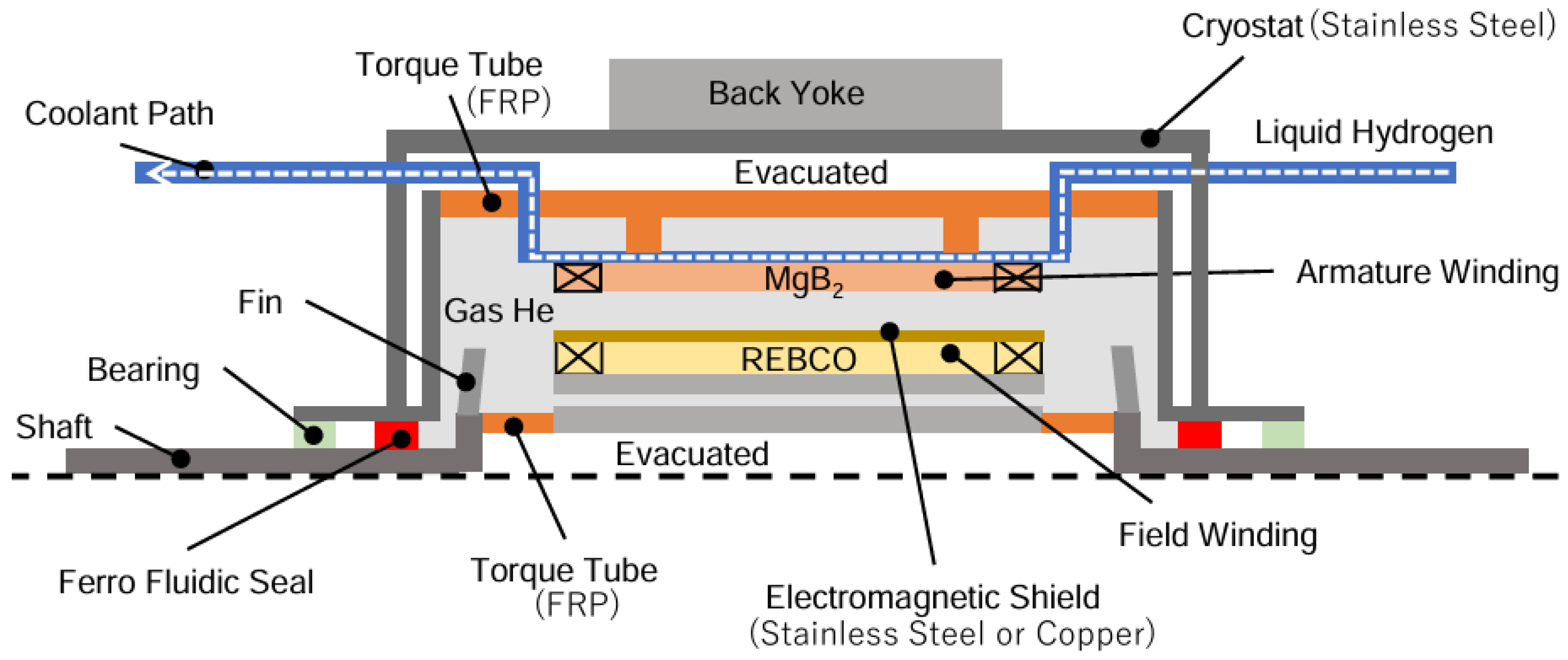
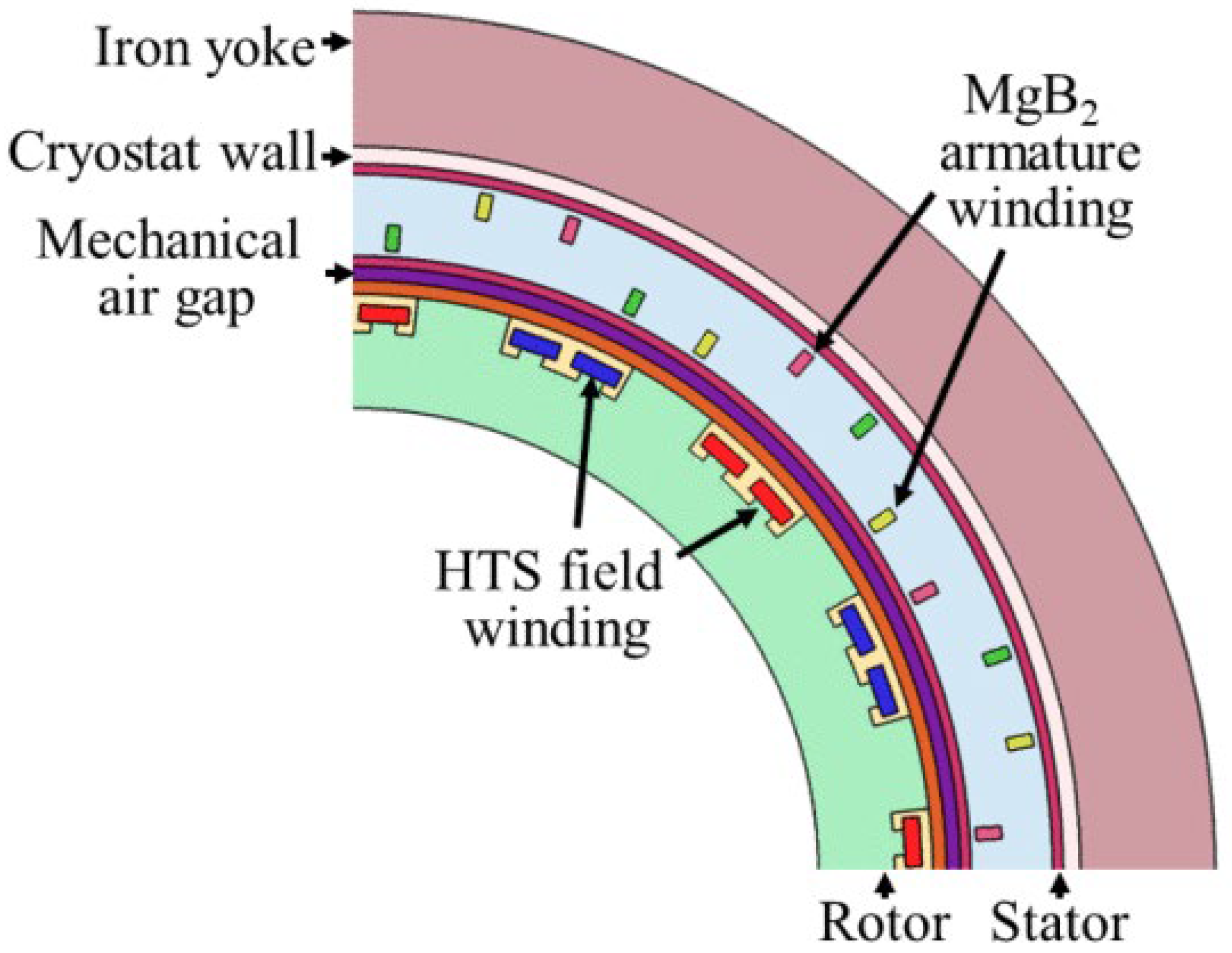
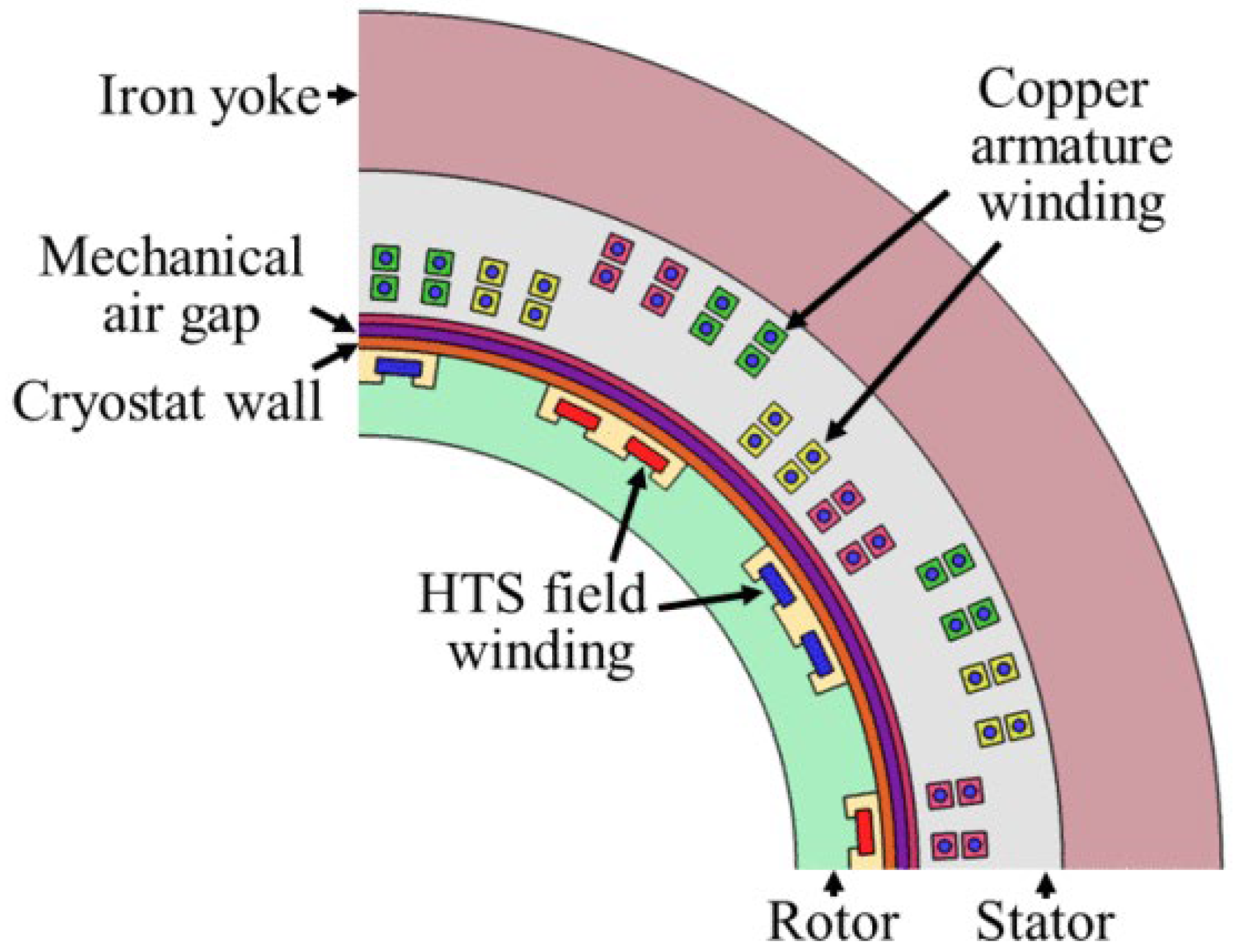
2.3.1. Superconducting Machine Cooling

LH2-cooled superconducting systems revolutionize aviation power conversion through cryogenic synergy. As shown in Figure 4, MgB2 windings at 30 K (LH2-cooled) demonstrate 15-fold current capacity enhancement over 77 K liquid nitrogen-cooled counterparts [29], reducing AC losses by 98% through near-zero resistivity (10−14 Ω·m). This enables 40 MW power transmission systems where superconducting CORC® cables at 20 K exhibit 7.7× lower thermal loads than hyperconducting aluminum alternatives, achieving 1.15× mass reduction despite TRL 4 maturity [30]. The inherent cooling capacity of evaporating LH2 (445 kJ/kg latent heat) provides “free” thermal management for electrical components, eliminating the need for auxiliary cryocoolers that typically consume 20–30% of system power [31].
Recent implementations validate this approach: Russia’s 5 MW fully superconducting generator employs modular LH2 cooling loops maintaining 30 ± 0.5 K stability under 150% overload conditions through real-time flow control algorithms [32]. The Nam Group’s hybrid system integrates PEMFCs with LH2-cooled motors, achieving 18.5 kW/kg power density through direct hydrogen phase-change cooling of YBCO stator coils [33]. As Figure 5 illustrates, Japan’s 5.5 MW prototype demonstrates direct-contact LH2 cooling of MgB2 armatures, though REBCO field windings still require supplemental 50 K helium cooling–a limitation targeted for elimination through advanced hydrogen reheating cycles in next-gen designs [34].
Strategic programs are accelerating implementation: The EU’s BRAVA initiative develops 3 MW LH2-cooled fuel cell stacks with integrated superconducting buses, while the UK’s H2GEAR project demonstrates a 28% mass reduction in regional jet electrical networks through cryogenic power distribution. These advancements position LH2 as the cornerstone of ultra-efficient “cold electric” propulsion, with NASA studies projecting 40–60% system efficiency gains over conventional architectures by 2035 [35].
The 2 MW fully superconducting motor prototype developed by Kyushu University (Figure 6) pioneers direct-contact LH2 cooling through armature winding immersion, achieving 22.4 K operational stability with <0.5% temperature fluctuation. While armatures employ phase-change hydrogen cooling (ΔT = 8 K across windings), field windings utilize gaseous hydrogen/helium coolant at 30–40 K through separate microchannel networks transitional solution pending helium-free designs [36].
In parallel, the LUT-TBEA consortium’s comparative study of 3 MW superconducting architectures (Figure 7 and Figure 8) reveals critical performance tradeoffs: The fully superconducting configuration with MgB2 armatures and REBCO fields achieves 98.2% efficiency through complete LH2 immersion cooling, albeit requiring complex cryogenic seals. Contrastingly, the hybrid design combining REBCO field cooling (−253 °C LH2 flow) with forced-air copper armature cooling (35 °C airflow at 15 m/s) reduces cryogenic complexity while maintaining 94.7% efficiency with 12% improvement over conventional oil-cooled equivalents [37].
Contrasting approaches emerge from the Moscow Aviation Institute’s 5 MW system simulations (Figure 9), demonstrating the safety limitations of direct immersion cooling. Their finite element analysis shows localized hydrogen gasification rates exceeding 0.8 L/s during 150% overload conditions, necessitating indirect cooling via vacuum-jacketed transfer lines that maintain 25 ± 2 K winding temperatures with 82% cooling efficiency. The companion AC-DC converter study reveals 15–18% switching loss reductions through cryogenic MOSFET operation at 30 K [38].
In the above narrative, both direct and indirect cooling are mentioned. As for the former, the coolant is in direct contact with the superconducting material, which can quickly take away the heat. It has high cooling efficiency and a low delay. However, this will also bring the issue of system complexity and higher maintenance costs. On the contrary, indirect cooling refers to the transfer of heat from the superconducting material to the coolant through an intermediate medium (e.g., cooling plates, heat exchangers, etc.), where the coolant does not directly contact the superconducting material.
LH2 cooling emerges as the optimal thermal management solution for aviation superconducting systems, combining cryogenic performance (Jc > 5 × 10⁴ A/mm2 at 20 K) with inherent fuel integration. Implementation success requires threefold optimization: (1) Material compatibility between superconductors (MgB2/REBCO) and hydrogen phases, (2) Dynamic cooling capacity matching electrical load variations, and (3) Safety-certified architectures preventing hydrogen permeation (leak rates <1 × 10⁻⁶ mbar·L/s). While current prototypes demonstrate technical feasibility (TRL 4–5), full-scale deployment demands further research into hydrogen sloshing mitigation, cryogenic insulation durability (>10⁷ thermal cycles), and hybrid cooling topologies for next-gen multi-MW propulsion systems.

2.3.2. Cryogenic Cooling of Power Electronics

Cryogenic operation fundamentally enhances power electronic performance, as demonstrated by UK studies revealing 23–28% efficiency gains in phase-leg modules at 77 K compared to 300 K operation [39]. NASA’s material characterization of MW-class inverters identifies silicon carbide (SiC) MOSFETs as optimal cryogenic switches, exhibiting 92% lower switching losses at 100 K versus conventional IGBTs [40]. Building upon these findings, the University of Illinois developed a 1 MW multilevel flying capacitor converter using gallium nitride (GaN) FETs, achieving breakthrough performance at −195 °C: 85% reduction in RDS (on) (2.1 mΩ to 0.3 mΩ), 16% threshold voltage increase (3.5 V to 4.06 V), and no carrier freeze-out effect was observed [41]. These advancements validate cryogenic cooling’s transformative potential for aviation power systems, where rewarmed hydrogen gas (40–80 K) provides integrated thermal management without introducing foreign cryogens [42,43].
Motor drive controllers require precise thermal control to balance semiconductor performance and reliability. Permanent magnet motor controllers achieve peak efficiency at 275 K with power module temperatures maintained above 223 K to prevent silicone encapsulant embrittlement [44]. Conventional liquid nitrogen cooling methods reduce copper winding resistivity by 78% (2.7 × 10⁻⁸ Ω·m to 0.6 × 10⁻⁸ Ω·m at 77 K) despite 12–15% inductance degradation, enabling compact EMI filter designs through cryogenic optimization [45,46]. In hydrogen-based systems, two thermal management strategies emerge: (1) Direct LH2 cooling (−253 °C) requiring tradeoff analysis between 35% resistance reduction and 22% inductance loss, or (2) Multi-stage hydrogen gas cooling (77 K equivalent) demanding 4 × increased flow rates (0.8 m/s vs. 0.2 m/s) to compensate for 98% lower volumetric heat capacity compared to liquid nitrogen.
Superconducting magnetic energy storage (SMES) systems revolutionize aviation power networks through 95% round-trip efficiency and 50 kW/kg power density—8× superior to lithium-ion alternatives [47]. Airbus’s ASCEND program demonstrates SMES viability for aircraft through 500 kVA prototypes achieving 5 ms response times, effectively replacing auxiliary power units in emergency scenarios. When integrated with LH2 cooling, SMES coils maintain 50 T fields with 0.01% daily current decay, enabling compact 3 MW backup systems weighing <800 kg—65% lighter than conventional generator sets.
In order to ensure the cryogenic cooling works successfully, insulation materials and systems for superconducting powertrain devices are an important part. Yazdani-Asrami et al. [48] researched various materials applications in future cryo-electrified aircraft, including solid insulation, paper insulation, and so on. Low-temperature performance and insulation must be considered before selecting material for electric devices [48].

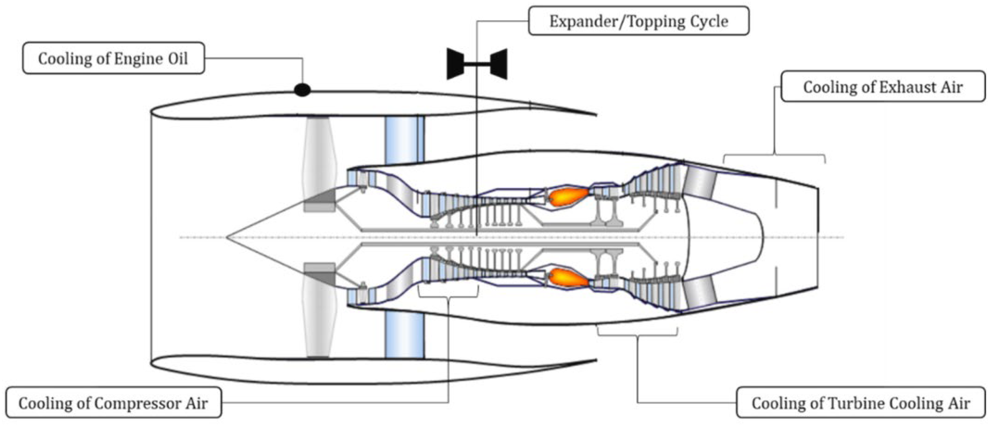
2.3.3. Aero-Engine Thermal Management via Liquid Hydrogen Cooling

Prolonged high-temperature operation severely impacts aero-engine longevity, with conventional ram air cooling exacerbating particulate matter (PM) deposition on heat exchangers-studies indicate 12–18% efficiency degradation from fouling accumulation over 2000 flight cycles [49,50]. Transitioning to hydrogen-based cooling eliminates this limitation through two mechanisms: (1) Hydrogen from storage tanks does not contain PM, and (2) Phase-change cooling capacity (445 kJ/kg) enables 35% higher heat rejection rates compared to air-based systems [51].
Liquid hydrogen (LH2) serves as a multifunctional coolant in advanced engine architectures through four primary thermal pathways (Figure 10):
(a)
Lubrication System Optimization
While traditional air-oil and fuel-oil heat exchangers achieve 60–75% thermal efficiency [52,53,54], hydrogen-oil systems uniquely combine lubricant cooling (−40 °C oil outlet temperature) with fuel preheating (ΔT = 150 K), simultaneously reducing bearing friction losses by 22% and improving combustion stability through 300 K fuel injection temperatures [55].
(b)
Compressor Inlet Conditioning
LH2 spray cooling of compressor intake air decreases inlet temperatures by 45–60 K, achieving 8–12% mass flow increase while reducing compressor work input by 15%. NASA’s X−57 Maxwell prototype demonstrates 23% pressure ratio improvement through cryogenic inlet cooling, validating theoretical models predicting 0.75% specific fuel consumption reduction per 10 K temperature drop [56,57].
(c)
Turbine Blade Protection
Replacing water-cooled turbine cooling air with LH2-based systems enables 1950 K turbine inlet temperatures (300 K increase) while maintaining blade metal temperatures below 1250 K. The dual-phase cooling architecture injects hydrogen-chilled air (400 K) through microchannels, creating protective film cooling layers with 85% adiabatic effectiveness—25% superior to conventional steam cooling [58,59,60,61].
(d)
Exhaust Heat Recovery
Integrated recuperators leverage 800–950 K exhaust gases to preheat LH2 from 20 K to 300 K prior to combustion, achieving 92% heat recovery efficiency. Optimized microchannel designs (Figure 11) reduce pressure losses to <2% while withstanding 500 + thermal cycles, as demonstrated in AVIC’s large aircraft cooling system upgrades [62,63,64,65,66,67,68]. This thermal regeneration improves combustion efficiency by 8% and reduces specific hydrogen consumption by 15 g/kN·s. The Aviation Industry Corporation of China’s (AVIC) First Aircraft Institute has pioneered these advancements through its next-gen cooling architecture (Figure 11), integrating all four thermal pathways into a unified hydrogen thermal management system. Experimental validation shows a 28% overall efficiency improvement compared to conventional air-cooled engines, with particulate emissions reduced to 0.01 g/kg fuel−98% below ICAO CAEP/12 standards [69,70].
The condition monitoring of these aero-engines under new coolant and fuel may be solved by these solutions. (1) probabilistic model. Zaccaria et al. [71] investigated the probabilistic model for aero-engines fleet condition monitoring, which concluded that the combination of performance model adaptation and a Bayesian network classifier is a superior method. (2) the local plastic stress and strain analysis (LPSA). Shanmuganathan et al. [72] proposed an algorithm, which is developed based on LPSA for LCF life consumption of high-speed rotors. Whatever the coolant is, the local plastic stress and strain of high-speed rotors must exist. Therefore, the approach may be a good way to monitor the condition. (3) flow path analysis. Gas path analysis (GPA) is the most popular performance-based concept for assessing the behavior of a gas turbine [73]. Despite the future adoption of hydrogen, analyzing the flow path may still be a valid way.

2.4. System-Level Hydrogen Utilization Strategy

After describing the subsystems above, selecting and integrating the subsystems is crucial. Yazdani-Asrami et al. [74] investigated the selection of cryogenic cooling systems for superconducting machines and discussed cooling fluid concerns, heat load concerns, and other issues.
The synergistic integration of hydrogen turbo-electric and fuel cell technologies necessitates optimized hydrogen flow management across multi-domain energy conversion systems. As schematized in Figure 12, our proposed architecture achieves high hydrogen utilization efficiency through five-stage cryogenic-to-thermal energy cascading (Since there is no 10MW class system yet, some of the following devices do not exist and the data are the normal average):
(a)
Primary Cryogenic Distribution
LH2 from vacuum-insulated storage (−253 °C, 1–2 bar [5]) bifurcates to superconducting components:
  • Forty percent mass flow drives the superconducting motor (SCM) powering boundary layer ingestion fans
  • Sixty percent feeds the superconducting generator (SCG) coupled to the hydrogen turbine
(b)
Electrical Power Conditioning
SCM effluent hydrogen (−180 °C) cools HTS DC cables (Jc = 5 × 10⁴ A/cm2) and AC busbars before converging at DC-DC Converter 1, subsequently preconditioning lubricant oil via plate-fin heat exchangers (ΔT = 120 K). Concurrently, SCG output hydrogen (−150 °C) distributes to three pathways:
  • Fifty-five percent to DC-DC Converter 2
  • Thirty percent charging superconducting magnetic storage (SMES)
  • Fifteen percent through DC-DC Converter 3
(c)
Thermal Energy Recovery
Converter 2 effluent (−90 °C) undergoes DC-AC inversion (THD < 3%) while cooling compressor intake air via microchannel charge air coolers (CAC), achieving an 18 K temperature reduction. SMES discharge hydrogen (−70 °C) and Converter 3 outflow (−85 °C) merge at AC-DC conversion stages, simultaneously chilling turbine cooling air through compact heat exchangers (ε = 0.88 [75]).
(d)
Combustion Preparation
All thermal streams converge in the regenerator, where 800–950 K exhaust gases preheat hydrogen to 300 K through counterflow ceramic matrices (effectiveness η = 0.92). This staged heating:
  • Elevates fuel cell inlet temperatures to 353 K (PEMFC optimal)
  • Preconditions combustion hydrogen for 98% LHV utilization
  • Recovers 35% of exhaust energy otherwise wasted
(e)
Final Energy Conversion
The regenerated hydrogen flow bifurcates for dual-mode power generation:
  • Seventy percent feeds PEMFC stacks (3.2 MW, 58% efficiency [76,77])
  • Thirty percent combusts in the hydrogen turbine (42% Brayton cycle efficiency)
This holistic approach reduces boil-off losses to <0.5%/day while maintaining cryogenic stability (ΔT < 2 K) across all superconducting components, validated through AVIC’s full-scale prototype testing [70].

3. Hydrogen Safety Research

While the aviation industry currently lacks dedicated hydrogen safety regulations, substantial progress has been achieved through multinational research initiatives and institutional collaborations. Australia’s Macquarie University Sustainable Energy Research Centre (MQ-SERC) specializes in hydrogen fuel cell vehicle safety assessments and provides technical consultancy for hydrogen infrastructure deployment. In Japan, Yokohama National University has partnered with industry stakeholders to develop safety distance calculation methodologies for hydrogen refueling stations, complemented by the National Institute of Advanced Industrial Science and Technology’s (AIST) quantitative risk assessments of operational hazards at such facilities. The UK’s Hydrogen Safety Engineering and Research Centre (HySAFER) at the University of Ulster pioneers numerical simulation techniques for hydrogen safety applications, establishing internationally recognized Best Practice Guidelines for computational modeling. European efforts include the Hydrogen Safety Committee’s (EHSP) safety planning frameworks derived from the Hydrogen Incident Accident Database (HIAD 2.0), alongside the EU-funded International Hydrogen Safety Association “HySafe”. In the United States, the Department of Energy’s Pacific Northwest National Laboratory collaborates with the American Institute of Chemical Engineers (AICHE) through the Center for Hydrogen Safety (CHS) to standardize safety protocols and educational resources. Concurrently, China’s Ministry of Transportation is formulating regulatory standards for hydrogen road transport, including liquid hydrogen logistics. These coordinated efforts have elevated global awareness of hydrogen safety challenges while establishing foundational frameworks for its secure integration into aviation and allied sectors.

3.1. Flammability and Explosivity

Hydrogen’s broad explosive concentration range (4–75%) and low molecular weight confer both high flammability and rapid diffusion capabilities, with the latter physical characteristic amplifying combustion risks during storage, transportation, and utilization [78]. Counterintuitively, experimental evidence suggests hydrogen’s explosive potential may be context-dependent. Washington State University’s Hydrogen Properties for Energy Research (HYPER) experiments employed rocket-propelled ignition tubes to test hydrogen leakage scenarios, revealing that ruptured hydrogen containers produced rapidly dissipating flames without explosive overpressure in 59 of 61 trials. Detonation occurred only under forced oxygen-hydrogen premixing conditions. Comparative testing with gasoline demonstrated prolonged fuel adherence to containers, resulting in sustained combustion and structural damage. These findings align with Chinese academic assessments concluding that hydrogen’s aviation risks are comparable to conventional jet fuels when accounting for its buoyant dispersion and transient combustion behavior [79], as quantitatively summarized in Table 4.

3.2. Hydrogen Corrosion

Hydrogen corrosion encompasses three interrelated mechanisms: hydrogen-induced blistering, hydrogen embrittlement, and hydrogen etching, which frequently coexist due to hydrogen’s dual characteristics of high chemical reactivity and material permeability [16,80]. When metallic materials such as high-strength steel interact with hydrogen, the gas progressively infiltrates the metal’s crystalline structure through adsorption, dissolution, and diffusion processes. Within the metal matrix, hydrogen may exist in various forms including solid solutions, hydrides, molecular aggregates, atomic dispersions, and ionic states. Hydrogen-induced blistering occurs when diffusing hydrogen atoms accumulate in internal voids, recombine into non-diffusible molecules, and generate critical internal pressures causing surface deformation or material rupture. Hydrogen embrittlement arises when dissolved hydrogen atoms amplify lattice strain, thereby degrading the material’s toughness and ductility through localized stress concentration. In contrast, hydrogen etching involves direct chemical reactions between hydrogen and metallic components, producing gaseous byproducts that induce cavity formation and microcrack propagation. Though both hydrogen embrittlement and etching cause material brittleness, their fundamental distinction lies in the latter’s association with chemical reactions and cavity generation [16,80]. Current aerospace material research targets hydrogen corrosion mitigation through advanced material development [81,82], with particular emphasis on microstructural property investigations [83]. However, the engineering challenge persists in creating universally reliable hydrogen-resistant materials.
Liquid hydrogen applications demand rigorous safety protocols requiring comprehensive leak detection systems and dispersion control strategies. The implementation of high-sensitivity hydrogen sensors enables real-time monitoring during storage and transportation, while automated alarm systems and emergency response plans are essential for managing leakage incidents and preventing ignition hazards [84]. The UK’s CONCERTO project significantly advanced this field through an integrated experimental platform simulating liquid hydrogen dispersion dynamics under varying temperature-pressure conditions, subsequently developing a multilayer detection system combining sensor networks with predictive diffusion modeling [85]. Experimental validation confirmed the system’s capability to detect early-stage hydrogen concentration anomalies and activate automated containment protocols. Concurrently, the European Union’s CONCERTO initiative established standardized certification frameworks for hydrogen technology safety compliance. Complementing these efforts, U.S. researchers engineered slosh-mitigation tank technology through computational fluid dynamics optimization [86]. This innovation employs internal baffle structures to suppress liquid hydrogen turbulence during storage, effectively reducing evaporation risks and pressure fluctuations while enhancing fuel transfer stability [86].

4. Challenges in Liquid Hydrogen Implementation

While superconducting machinery demonstrates exceptional efficiency and operational reliability, the substantial mass and volumetric penalties imposed by cryogenic cooling infrastructure remain critical engineering constraints. Divergent optimal cooling temperatures across electrical subsystems necessitate precise thermal management of both liquid hydrogen (20 K) and its cryogenic gaseous phase post-vaporization, presenting significant control system challenges.

4.1. Lightweight Design of Liquid Hydrogen Cooling System

Liquid hydrogen storage at 20 K (1–2 bar) remains the predominant technical approach [5], with extensive research validating its necessity for aerospace applications [51,87,88,89]. Despite the thermodynamic advantages of hydrogen cryogenics, the parasitic mass of associated cooling systems demands innovative lightweight solutions that maintain thermal performance. Pavlos Rompokos et al. [90] demonstrated that strategic venting of gaseous hydrogen during cruise operations reduces internal tank pressures by 33.6%, enabling substantial wall thickness reductions through decreased structural load requirements. This systematic pressure management approach effectively decouples tank mass from storage capacity limitations.
The traditional formula for calculating weight efficiency [91] is
η = m f m f + m t
mf is the mass of fuel, mt is the mass of tank.
Christopher Winnefeld et al. [92] propose a design for an aerospace cryogenic liquid hydrogen storage tank, show that the tank design should be closely related to the mission, and propose a new cryogenic tank weight efficiency formula:
η r e q = η r m = m r e q m f + m t
mf is the mass of fuel, mt is the mass of the tank, and the parameter r m depends strongly on the adiabatic properties, since it indirectly reflects the share of outgassed hydrogen in the total hydrogen mass parameter [92]. However, the mass of safety structures such as tank supports is not included. Therefore, the weight efficiency should include the mass of all safety structures so that it is accurate.
The 28-inch diameter × 53-inch-long flying tank demonstrated by Gloyer-Taylor Laboratories on 13 March 2024, weighs only 15 kg, including the inner liner, outer vacuum shell, multilayer vacuum insulation, inner tubes, and sensors, but can hold up to 19 kg of LH2, allowing for the efficient storage of liquid hydrogen.

4.2. Cryogenic Hydrogen Pipeline Configuration and Thermal Management

The liquid hydrogen delivery system must ensure complete thermal absorption from component-generated heat loads while maintaining precise temperature regulation at each operational module. Figure 12 illustrates a hydrogen distribution framework optimized for module-specific thermal zones. However, practical implementation requires a comprehensive analysis of heat exchanger efficiency, thermal load capacities, and subsystem-specific operational parameters.
Hydrogen’s thermodynamic behavior exhibits critical phase-dependent characteristics: at atmospheric pressure, it demonstrates a negative Joule–Thomson coefficient above 195 K, resulting in temperature elevation during throttling processes. Conversely, below 195 K, the positive coefficient induces temperature reduction under identical conditions. Engine hydrogen transport line design must account for thermal effects arising from ortho-para hydrogen conversion and Joule–Thomson coefficient variations [93]. This thermodynamic behavior necessitates integrated modeling of transient thermal profiles and pressure-volume relationships during phase transitions.
Currently, artificial intelligence (AI) with powerful capabilities is developing rapidly. Bonab et al. [94] utilize AI to predict the hydrogen transfer coefficient in the flow boiling of liquid hydrogen as fuel and cryogenic coolant in future hydrogen-powered cryo-electric aviation, which provides novel thinking for cryogenic hydrogen pipeline configuration and thermal management.

5. Future Perspectives

(a)
High-efficiency superconducting motor architectures are projected to dominate next-generation 10 MW-class aeronautical power systems, with scalability potential exceeding current megawatt-range limitations.
(b)
The integration of liquid hydrogen as a dual-purpose coolant and fuel within multi-electric aircraft systems will enable the complete elimination of auxiliary cryogens (nitrogen, helium), thereby resolving historical challenges of parasitic mass penalties and operational redundancy. This synergistic approach promises to redefine aircraft energy density parameters while achieving net-zero-emission targets through closed-loop hydrogen utilization.
(c)
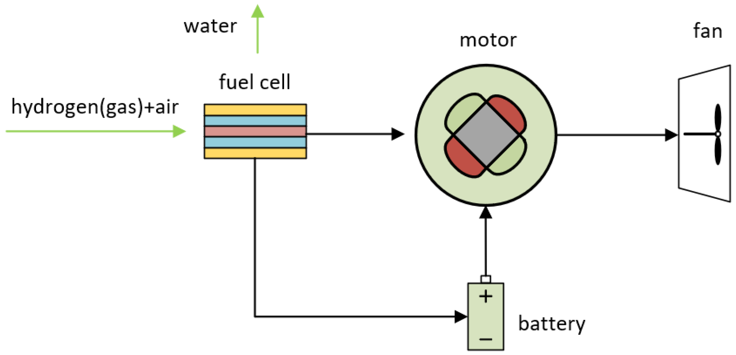
The liquid hydrogen application process proposed in this paper successfully couples two technologies, fuel cell and turbo-electric, and the experimental study and application of this technological solution is a hot topic for the future.

6. Conclusions

This study establishes the technical viability of liquid hydrogen application in aero-engine more-electrical systems, particularly for superconducting machinery and high-power electrical components, while demonstrating its compelling thermodynamic advantages over conventional cryogenic cooling methodologies. And it investigates the selection basis for cryogenic cooling systems and material suitability. A novel aircraft-integrated liquid hydrogen distribution architecture is proposed, addressing both propulsion and thermal management requirements through unified hydrogen utilization.
Critical implementation challenges are identified, including thermal management complexities during phase transitions, cryogenic material durability under extreme thermal cycling, and system-level mass optimization constraints. In response to these challenges, directions for solving the problems have been proposed, such as condition monitoring of hydrogen-fueled aero-engines and the application of AI to cryogenic cooling systems.

Author Contributions

Z.Z.: Methodology, Data curation, Visualization; Writing—original draft, Writing—review & editing; J.M.: Investigation; J.H.: Data curation; Z.G.: Methodology; J.X.: Writing—review & editing; J.C.: Conceptualization, Writing—review & editing. All authors have read and agreed to the published version of the manuscript.

Funding

National Key Technologies R & D Program of China: NO. 2024YFC3321804.

Conflicts of Interest

The authors declare that they have no known competing financial interests or personal relationships that could have appeared to influence the work reported in this paper.

References

  1. Xiang, Q.; Hu, X.; Wang, M.; Qiao, X.; Wang, S. Observations on the Development of Hydrogen-powered Aircraft Propulsion System. Aeroengine 2024, 50, 1–9. (In Chinese) [Google Scholar]
  2. Ji, S.; Liu, J.; Zhu, Y. Exploring the low-carbon development path of China’s civil aviation energy use in the context of “dual carbon” goals. Int. Pet. Econ. 2022, 30, 31–39. [Google Scholar]
  3. Abrantes, I.; Ferreira, A.F.; Silva, A.E.; Costa, M. Sustainable aviation fuels and imminent technologies-CO2 emissions evolution towards 2050. J. Clean. Prod. 2021, 313, 127937. [Google Scholar]
  4. Zhang, Z.; Xu, Y.; Yao, Y.; Xu, Y. Electric Power System and Key Technologies of More Electric Aircraft. J. Nanjing Univ. Aeronaut. Astronaut. 2022, 54, 969–984. (In Chinese) [Google Scholar]
  5. Tiwari, S.; Pekris, M.J.; Doherty, J.J. A review of liquid hydrogen aircraft and propulsion technologies. Int. J. Hydrog. Energy 2024, 57, 1174–1196. [Google Scholar]
  6. Ansell, P.J. Hydrogen-Electric Aircraft Technologies and Integration: Enabling an environmentally sustainable aviation future. IEEE Electrif. Mag. 2022, 10, 6–16. [Google Scholar]
  7. Balachandran, T.; Lee, D.; Salk, N.; Haran, K.S. A fully superconducting air-core machine for aircraft propulsion. IOP Conf. Ser. Mater. Sci. Eng. 2020, 756, 12030. [Google Scholar]
  8. European Union Aviation Safety Agency. Certification Specifications and Acceptable Means of Compliance for Large Aeroplanes (CS-25); European Union Aviation Safety Agency: Cologne, Germany, 2023. [Google Scholar]
  9. Han, Y.Q. Progress of Hydrogen Powered Aviation in 2023. Aerosp. Power 2024, 1, 38–42. (In Chinese) [Google Scholar]
  10. Subodh, K.M.; John, Z.G.; Steven, M.A.; Sullivan, R.M.; Manderscheid, J.M.; Murthy, P.L.N. Review of Current State of the Art and Key Design Issues with Potential Solutions for Liquid Hydrogen Cryogenic Storage Tank Structures for Aircraft Applications. 2006. Available online: https://ntrs.nasa.gov/citations/20060056194 (accessed on 10 December 2024).
  11. Chen, H.; Yang, X.; Wang, X. Study on Adiabatic Performance and Lightweight of Airborne Liquid HydrogenStorage Tank. Aeronaut. Sci. Technol. 2024, 35, 36–46. (In Chinese) [Google Scholar]
  12. Rompokos, P.; Rolt, A.; Nalianda, D.; Isikveren, A.T.; Senné, C.; Gronstedt, T.; Abedi, H. Synergistic Technology Combinations for Future Commercial Aircraft Using Liquid Hydrogen. J. Eng. Gas Turbines Power 2021, 143, 071017. [Google Scholar]
  13. Mantzaroudis, V.K.; Theotokoglou, E. Computational Analysis of Liquid Hydrogen Storage Tanks for Aircraft Applications. Materials 2023, 16, 2245. [Google Scholar] [CrossRef] [PubMed]
  14. Virdi, P.S.; Guo, W.; Cattafesta, L.; Cheetham, P.; Cooley, L.; Gladin, J.; He, J.; Ionel, D.M.; Kim, C.; Li, H.; et al. Liquid hydrogen storage and transfer-control system for integrated zero emission aviation (IZEA). IOP Conf. Ser. Mater. Sci. Eng. 2024, 1302, 012024. [Google Scholar]
  15. Nam, G.; Sung, H.; Ha, D.; No, H.-W.; Koo, T.-H.; Ko, R.-K.; Park, M. Design and Analysis of Cryogenic Cooling System for Electric Propulsion System Using Liquid Hydrogen. Energies 2023, 16, 527. [Google Scholar] [CrossRef]
  16. Wan, X.; Wang, P.; Zhang, H.; Zhang, C.; Zhou TMa, C.; Lin, B.; Zhou, R.; Tang, Y.; Fu, Y. A Review of the Key Technologies of Hydrogen Energy in the Aviation Engine Industry. J. Xihua Univ. (Nat. Sci. Ed.) 2024, 43, 8–15+46. (In Chinese) [Google Scholar]
  17. Liao, Z.Q. Research on the Development of Hybrid Electric Propulsion System. Aerosp. Power 2018, 2, 45–50. (In Chinese) [Google Scholar]
  18. International Civil Aviation Organization. Report of the Tenth Meeting of the Committee on Aviation Environmental Protection; International Civil Aviation Organization: Montreal, Canada, 2016. [Google Scholar]
  19. Nategh, S.; Barber, D.; Boglietti, A.; Lindberg, D.; Aglen, O.; Brammer, R. A study on thermal effects of different potting strategies in traction motors. In Proceedings of the 2018 IEEE International Conference on Electrical Systems for Aircraft, Railway, Ship Propulsion and Road Vehicles & International Transportation Electrification Conference (ESARS-ITEC), Nottingham, UK, 7–9 November 2018; pp. 1–6. [Google Scholar]
  20. Kulan, M.C.; Baker, N.J. Development of a thermal equivalent circuit to quantify the effect of thermal paste on heat flow through a permanent magnet alternator. IEEE Trans. Ind. Appl. 2018, 55, 1261–1271. [Google Scholar] [CrossRef]
  21. Polikarpova, M.; Ponomarev, P.; Lindh, P.; Petrov, I.; Jara, W.; Naumanen, V.; Tapia, J.A.; Pyrhonen, J. Hybrid cooling method of axial-flux permanent-magnet machines for vehicle applications. IEEE Trans. Ind. Electron. 2015, 62, 7382–7390. [Google Scholar] [CrossRef]
  22. Polikarpova, M.; Lindh, P.M.; Tapia, J.A.; Pyrhönen, J.J. Application of potting material for a 100 kW radial flux PMSM. In Proceedings of the 2014 International Conference on Electrical Machines (ICEM), Berlin, Germany, 2–5 September 2014; pp. 2146–2151. [Google Scholar]
  23. Li, H.; Klontz, K.W.; Ferrell, V.E.; Barber, D. Thermal models and electrical machine performance improvement using encapsulation material. IEEE Trans. Ind. Appl. 2016, 53, 1063–1069. [Google Scholar] [CrossRef]
  24. Li, L.; Zhang, J.; Zhang, C.; Yu, J. Research on electromagnetic and thermal issue of high-efficiency and high-power-density outer-rotor motor. IEEE Trans. Appl. Supercond. 2016, 26, 5204805. [Google Scholar] [CrossRef]
  25. Mueller, M.A.; Burchell, J.; Chong, Y.C.; Keysan, O.; McDonald, A.; Galbraith, M.; Subiabre, E.J.P.E. Improving the thermal performance of rotary and linear air-cored permanent magnet machines for direct drive wind and wave energy applications. IEEE Trans. Energy Convers. 2018, 34, 773–781. [Google Scholar] [CrossRef]
  26. Chen, Z. Study on the Energy-Saving Technology Formotors Based on Heat Conduction and Dissipationand Its Applications; Donghua University: Shanghai, China, 2016. (In Chinese) [Google Scholar]
  27. Yang, Y.; Bilgin, B.; Kasprzak, M.; Nalakath, S.; Sadek, H.; Preindl, M.; Cotton, J.; Schofield, N.; Emadi, A. Thermal management of electric machines. IET Electr. Syst. Transp. 2017, 7, 104–116. [Google Scholar]
  28. Popescu, M.; Staton, D.A.; Boglietti, A.; Cavagnino, A.; Hawkins, D.; Goss, J. Modern heat extraction systems for power traction machines—A review. IEEE Trans. Ind. Appl. 2016, 52, 2167–2175. [Google Scholar]
  29. Dezhin, D.; Dezhina, I.; Ilyasov, R. Superconducting Propulsion System with LH2 Cooling for All-Electric Aircraft. J. Physics. Conf. Ser. 2020, 1559, 12143. [Google Scholar] [CrossRef]
  30. Sebastian, M.A.P.; Haugan, T.J.; Kovacs, C.J. Design and Scaling Laws of a 40-MW-class Electric Power Distribution System for Liquid-H2 Fuel-Cell Propulsion. In Proceedings of the 2021 AIAA/IEEE Electric Aircraft Technologies Symposium (EATS), Denver, CO, USA, 11–13 August 2021; pp. 1–12. [Google Scholar]
  31. Sirimanna, S.; Balachandran, T.; Salk, N.; Xiao, J.; Lee, D.; Haran, K. Electric Propulsors for Zero-Emission Aircraft: Partially superconducting machines. IEEE Electrif. Mag. 2022, 10, 43–56. [Google Scholar]
  32. Dezhin, D.; Ilyasov, R. Development of Fully Superconducting 5 MW Aviation Generator with Liquid Hydrogen Cooling. EUREKA Phys. Eng. 2022, 1, 62–73. [Google Scholar]
  33. Nam, G.; Le Dinh Vuong Sung, H.; Sung, H.-J.; Lee, S.J.; Park, M. Conceptual Design of an Aviation Propulsion System Using Hydrogen Fuel Cell and Superconducting Motor. IEEE Trans. Appl. Supercond. 2021, 31, 5202307. [Google Scholar]
  34. Terao, Y.; Akasaka, K.; Ohsaki, H.; Okai, K.; Taguchi, H. Electromagnetic analysis of fully superconducting motors employing dilute gas rotor and liquid hydrogen stator cooling structure. J. Phys. Conf. Ser. 2023, 2545, 12027. [Google Scholar]
  35. Nøland, J.; Hartmann, C.; Mellerud, R. Next-Generation Cryo-Electric Hydrogen-Powered Aviation. TechRxiv 2021. [Google Scholar] [CrossRef]
  36. Sugouchi, R.; Komiya, M.; Miura, S.; Iwakuma, M.; Yoshida, K.; Sasayama, T.; Yoshida, T.; Yamamoto, K.; Sasamori, Y.; Honda, H.; et al. Conceptual Design and Electromagnetic Analysis of 2 MW Fully Superconducting Synchronous Motors with Superconducting Magnetic Shields for Turbo-Electric Propulsion System. IEEE Trans. Appl. Supercond. 2020, 30, 3601905. [Google Scholar] [CrossRef]
  37. Liu, D.; Lin, J.; Petrov, I.; Lindh, P.; Aarniovuori, L. Preliminary Assessment of New Armature Winding Concepts for High-Speed Superconducting Motors. IEEE Trans. Appl. Supercond. 2024, 34, 5202606. [Google Scholar]
  38. Dezhin, D.S.; Dezhina, I.N. Development of the Future Aircraft Propulsion System Based on HTS Electrical Equipment with Liquid Hydrogen Cooling. IEEE Trans. Appl. Supercond. 2022, 32, 3601105. [Google Scholar]
  39. Elwakeel, A.; Feng, Z.; McNeill, N.; Zhang, M.; Williams, B.; Yuan, W. Study of Power Devices for Use in Phase-Leg at Cryogenic Temperature. IEEE Trans. Appl. Supercond. 2021, 31, 5000205. [Google Scholar]
  40. Wang, F.; Chen, R.; Gui, H.; Niu, J.; Tolbert, L.; Costinett, D.; Blalock, B.; Liu, S.; Hull, J.; Williams, J.; et al. MW-Class Cryogenically-Cooled Inverter for Electric-Aircraft Applications. In Proceedings of the 2019 AIAA/IEEE Electric Aircraft Technologies Symposium (EATS), Indianapolis, IN, USA, 22–24 August 2019; pp. 1–9. [Google Scholar]
  41. Jansen, R.; Bowman, C.; Jankovsky, A.; Dyson, R.; Felder, J. Overview of NASA Electrified Aircraft Propulsion Research for Large Subsonic Transports. In Proceedings of the 53rd AIAA/SAE/ASEE Joint Propulsion Conference, Atlanta, GA, USA, 10–12 July 2017. [Google Scholar]
  42. Liao, Y.; Elwakeel, A.; Xiao, Y.; Alzola, R.P.; Zhang, M.; Yuan, W.; Feliciano, A.J.C.; Graber, L. Review of semiconductor devices and other power electronics components at cryogenic temperature. iEnergy 2024, 3, 95–107. [Google Scholar]
  43. Gui, H.; Chen, R.; Niu, J.; Zhang, Z.; Tolbert, L.M.; Wang, F.F.; Blalock, B.J.; Costinett, D.; Choi, B.B. Review of Power Electronics Components at Cryogenic Temperatures. IEEE Trans. Power Electron. 2020, 35, 5144–5156. [Google Scholar]
  44. Sun, X.; Cheng, W.; Mu, Z.; Song, Y. White Paper on the Development of Electric Aircraft. Aeronaut. Sci. Technol. 2019, 30, 1–7. (In Chinese) [Google Scholar]
  45. Chen, R.; Dong, Z.; Zhang, Z.; Gui, H.; Niu, J.; Ren, R.; Wang, F.; Tolbert, L.M.; Blalock, B.J.; Costinett, D.J.; et al. Core Characterization and Inductor Design Investigation at Low Temperature. In Proceedings of the 2018 IEEE Energy Conversion Congress and Exposition (ECCE), Portland, OR, USA, 23–27 September 2018; pp. 4218–4225. [Google Scholar]
  46. Chen, R.; Niu, J.; Ren, R.; Gui, H.; Wang, F.; Tolbert, L.; Choi, B.; Brown, G. A Cryogenically-Cooled MW Inverter for Electric Aircraft Propulsion. In Proceedings of the 2020 AIAA/IEEE Electric Aircraft Technologies Symposium (EATS), New Orleans, LA, USA, 26–28 August 2020; pp. 1–10. [Google Scholar]
  47. Alafnan, H.; Pei, X.; Khedr, M.; Alsaleh, I.; Albaker, A.; Alturki, M.; Mansour, D.-E.A. The Possibility of Using Superconducting Magnetic Energy Storage/Battery Hybrid Energy Storage Systems Instead of Generators as Backup Power Sources for Electric Aircraft. Sustainability 2023, 15, 1806. [Google Scholar] [CrossRef]
  48. Yazdani-Asrami, M.; Seyyedbarzegar, S.M.; Zhang, M.; Yuan, W. Insulation Materials and Systems for Superconducting Powertrain Devices in Future Cryo-Electrified Aircraft: Part I—Material Challenges and Specifications, and Device-Level Application. IEEE Electr. Insul. Mag. 2022, 38, 23–36. [Google Scholar]
  49. Wright, S.J.; Dixon-Hardy, D.W.; Heggs, P.J. Aircraft air conditioning heat exchangers and atmospheric fouling. Therm. Sci. Eng. Prog. 2018, 7, 184–202. [Google Scholar]
  50. Wright, S.; Andrews, G.; Sabir, H. A review of heat exchanger fouling in the context of aircraft air-conditioning systems, and the potential for electrostatic filtering. Appl. Therm. Eng. 2009, 29, 2596–2609. [Google Scholar]
  51. Tamburrano, P.; Romagnuolo, L.; Frosina, E.; Caramia, G.; Distaso, E.; Sciatti, F.; Senatore, A.; De Palma, P.; Amirante, R. Fuels systems and components for future airliners fuelled with liquid hydrogen. J. Phys. Conf. Ser. 2022, 2385, 12041. [Google Scholar] [CrossRef]
  52. Cai, H.K.; Su, L.J.; Liao, Y.D.; Weng, Z.; Xu, C. Heat Dissipation Characteristics Analysis of Surface Air-Oil Heat Exchanger Applied in Aircraft Engine. J. Southwest Jiaotong Univ. 2021, 56, 214–220. (In Chinese) [Google Scholar]
  53. Lu, Y.; Liu, Z. Heat transfer characteristics calculation for aero-engine shell-tube fuel-oil heat exchanger. J. Aerosp. Power 2014, 29, 2830–2835. (In Chinese) [Google Scholar]
  54. Su, Z.; Mao, H.; Song, G. Thermoanalysis Method of Aeroengine Lubrication System Based on Heat Management Technology. Aeroengine 2016, 42, 44–50. (In Chinese) [Google Scholar]
  55. Li, M.; Chen, J. Analysis to Hydrogen Gas Turbine Thermal Management Technology of Fly Zero. Hydrog. Powered Aviat. 2022, 4, 29–32. (In Chinese) [Google Scholar]
  56. Liu, J.; Luo, N.; Li, J.; Li, K. Research Status and Development Constraints of Hydrogen Aero Engines. Mater. Res. Appl. 2024, 18, 299–308. (In Chinese) [Google Scholar]
  57. Lin, A.; Zheng, Q.; Zhang, H.; Jiang, Y. Analysis of mass injection cooling on aero-enginecompressor characteristics. J. Harbin Eng. Univ. 2019, 40, 1608–1615. (In Chinese) [Google Scholar]
  58. Al-Ibrahim, A.M.; Varnham, A. A review of inlet air-cooling technologies for enhancing the performance of combustion turbines in Saudi Arabia. Appl. Therm. Eng. 2010, 30, 1879–1888. [Google Scholar] [CrossRef]
  59. Najjar, Y.S.H. Enhancement of performance of gas turbine engines by inlet air cooling and cogeneration system. Appl. Therm. Eng. 1996, 16, 163–173. [Google Scholar] [CrossRef]
  60. Dos Santos, A.P.P.; Andrade, C.R.; Zaparoli, E.L. Comparison of Different Gas Turbine Inlet Air Cooling Methods. World Acad. Sci. Eng. Technol. 2012, 61, 45. [Google Scholar]
  61. Li, W.; Cao, J.; Xiao, W. Technology and Development Trend of Hydrogen Gas Turbine. Hydrog. Powered Aviat. 2022, 2, 39–42. (In Chinese) [Google Scholar]
  62. Patrao, A.C.; Jonsson, I.; Xisto, C.; Lundbladh, A.; Grönstedt, T. Compact heat exchangers for hydrogen-fueled aero engine intercooling and recuperation. Appl. Therm. Eng. 2024, 243, 122538. [Google Scholar]
  63. Misirlis, D.; Vlahostergios, Z.; Flouros, M.; Salpingidou, C.; Donnerhack, S.; Goulas, A.; Yakinthos, K. Optimization of Heat Exchangers for Intercooled Recuperated Aero Engines. Aerospace 2017, 4, 14. [Google Scholar] [CrossRef]
  64. Zhao, B.; Xuan, Y. A review of research on intercoolers and recuperators in aero-engines. Acta Aeronaut. Astronaut. Sin. 2017, 38, 1–21. (In Chinese) [Google Scholar]
  65. Decang, L.; Yong, K.; Wen, G.; Qiuyue, Z. Intercooled Recuperative Aero Engine System Optimization. J. Eng. Gas Turbines Power 2022, 144, 81011. [Google Scholar]
  66. Deng, H.; Li, L.; Yang, J.; Jiang, H.; Wang, J. Development and application prospect of light and high efficiency heatexchanger in aviation and aerospace. J. Aerosp. Power 2022, 37, 2272–2285. (In Chinese) [Google Scholar]
  67. Carozza, A.; Murshed, S.M.S. Heat Exchangers in the Aviation Engineering. Murshed, S.M.S., Lopes, M.M., Eds.; IntechOpen: Rijeka, Croatia, 2017. [Google Scholar]
  68. Saltzman, D.; Bichnevicius, M.; Lynch, S.; Simpson, T.W.; Reutzel, E.W.; Dickman, C.; Martukanitz, R. Design and evaluation of an additively manufactured aircraft heat exchanger. Appl. Therm. Eng. 2018, 138, 254–263. [Google Scholar]
  69. International Civil Aviation Organization. Report of the Twelfth Meeting of the Committee on Aviation Environmental Protection; International Civil Aviation Organization: Montreal, Canada, 2022. [Google Scholar]
  70. Ma, H.; Dang, X. Operation Optimization for Cooling System of Large Aircraft. In Proceedings of the 2023 Asia-Pacific International Symposium on Aerospace Technology, Singapore, 2 July 2024; pp. 609–624. [Google Scholar]
  71. Zaccaria, V.; Fentaye, A.D.; Stenfelt, M.; Kyprianidis, K.G. Probabilistic Model for Aero-Engines Fleet Condition Monitoring. Aerospace 2020, 7, 66. [Google Scholar] [CrossRef]
  72. Shanmuganathan, V.K.; Haran, A.P.; Gayathri, N. Condition monitoring maintenance of aero-engines through LUMS—A method for the implementation of Lean tools. Measurement 2015, 73, 226–230. [Google Scholar]
  73. Tahan, M.; Tsoutsanis, E.; Muhammad, M.; Karim, Z.A.A. Performance-based health monitoring, diagnostics and prognostics for condition-based maintenance of gas turbines: A review. Appl. Energy 2017, 198, 122–144. [Google Scholar]
  74. Yazdani-Asrami, M.; Sadeghi, A.; Atrey, M.D. Selecting a cryogenic cooling system for superconducting machines: General considerations for electric machine designers and engineers. Int. J. Refrig. 2022, 140, 70–81. [Google Scholar]
  75. Tano, I.; Rasouli, E.; Ziev, T.; Seo, J.; Lamprinakos, N.; Vaishnav, P.; Rollett, A.; Wu, Z.; Narayanan, V. A Scalable Compact Additively Manufactured Molten Salt to Supercritical Carbon Dioxide Heat Exchanger for Solar Thermal Application. J. Sol. Energy Eng. 2023, 146, 11007. [Google Scholar]
  76. Song, S.; Douvartzides, S.; Tsiakaras, P. Exergy analysis of an ethanol fuelled proton exchange membrane (PEM) fuel cell system for automobile applications. J. Power Sources 2005, 145, 502–514. [Google Scholar]
  77. Wang, Q.; Zhou, Z.; Lai, Y.; You, Y.; Liu, J.-G.; Wu, X.-L.; Terefe, E.; Chen, C.; Song, L.; Rauf, M.; et al. Phenylenediamine-Based FeNx/C Catalyst with High Activity for Oxygen Reduction in Acid Medium and Its Active-Site Probing. J. Am. Chem. Soc. 2014, 136, 10882–10885. [Google Scholar] [PubMed]
  78. Abohamzeh, E.; Salehi, F.; Sheikholeslami, M.; Abbassi, R.; Khan, F. Review of hydrogen safety during storage, transmission, and applications processes. J. Loss Prev. Process Ind. 2021, 72, 104569. [Google Scholar]
  79. Zhang, Y.J.; Peng, J.; Qian, Y.P.; Suo, J.; Ming, P.; Wan, Q.; Wang, A.; Yao, X. Key Technologies and Challenges of Hydrogen Powered Aviation. Aerosp. Power 2021, 1, 20–23. (In Chinese) [Google Scholar]
  80. Li, Y.; Zhao, Y.S.; Zhang, M.; Sun, Z.; Ye, X. Research Progress on Hydrogen Condition Performance of Aero Engine Materials. Technology 2022, 5, 36–38. (In Chinese) [Google Scholar]
  81. Zan, N.; Luo, X. Analysis on Influence Factors of Hydrogen Embrittlement Behavior of High Manganese Austenitic TWIP Steel for Aero Engine. J. New Ind. 2018, 8, 57–64. (In Chinese) [Google Scholar]
  82. Karaveli, K.K.; Kalaycıoğlu, M.; Bal, B.; Saracyakupoglu, T. Critical Failures in Aviation Components: The Role of Hydrogen Embrittlement. Aerosp. Eng. 2024, preprint. [Google Scholar] [CrossRef]
  83. Saulin, D.; Kuzminykh, K.; Poylov, V.Z. Determination of hydrogen influence on microhardness and microstructure characteristics of aviation alloys. Black Metall. 2024, 67, 332–339. [Google Scholar] [CrossRef]
  84. Bagarello, S. A short overview of hydrogen storage for sustainable aviation. In Aerospace Science and Engineering: IV Aerospace PhD-Days; Materials Research Forum LLC.: Millersville, PA, USA, 2024. [Google Scholar]
  85. Benson, C.M.; Ingram, J.; Battersby, P.; Mba, D.; Sethi, V.; Rolt, A.M. An Analysis of Civil Aviation Industry Safety Needs for the Introduction of Liquid Hydrogen Propulsion Technology. In Volume 3: Coal, Biomass, Hydrogen, and Alternative Fuels; Cycle Innovations; Electric Power; Industrial and Cogeneration; Organic Rankine Cycle Power Systems; ASME: New York, NY, USA, 2019. [Google Scholar]
  86. Ryali, L.; Stautner, W.; Mariappan, D. Impact of Internal Baffle Designs on Liquid Hydrogen Sloshing in Cryogenic Aircraft Fuel Tanks. IOP Conf. Ser. Mater. Sci. Eng. 2024, 1301, 012068. [Google Scholar]
  87. Brewer, G.D. Hydrogen Aircraft Technology, 1st ed; Routledge: London, UK, 1991. [Google Scholar]
  88. Hughes, C.; Gear, C.; Milne, K.; Webb, S.; Debney, D.; Kumar, N.; Howard, M.; Whillier, M.; Galsworthy, T.; Newbury, S.; et al. FLY ZERO: Our Vision for Zero Carbon Emission Air Travel. Available online: https://www.ati.org.uk/wp-content/uploads/2022/03/FZO-ALL-REP-0004-FlyZero-Our-Vision-for-Zero-Carbon-Emission-Air-Travel.pdf (accessed on 19 January 2025).
  89. Westenberger. Final Technical Report: Liquid Hydrogen Fuelled Aircraft—System Analysis. Available online: https://www.fzt.haw-hamburg.de/pers/Scholz/dglr/hh/text_2004_02_26_Cryoplane.pdf (accessed on 19 January 2025).
  90. Rompokos, P.; Rolt, A.; Nalianda, D.; Sibilli, T.; Benson, C. Cryogenic Fuel Storage Modelling and Optimisation for Aircraft Applications: Turbo Expo: Power for Land, Sea, and Air. In Volume 6: Ceramics and Ceramic Composites; Coal, Biomass, Hydrogen, and Alternative Fuels; Microturbines, Turbochargers, and Small Turbomachines; V006T03A001; ASME: New York, NY, USA, 2021. [Google Scholar]
  91. Verstraete, D. The Potential of Liquid Hydrogen for Long Range Aircraft Propulsion; Cranfield University: Bedford, UK, 2009. [Google Scholar]
  92. Winnefeld, C.; Kadyk, T.; Bensmann, B.; Krewer, U.; Hanke-Rauschenbach, R. Modelling and Designing Cryogenic Hydrogen Tanks for Future Aircraft Applications. Energies 2018, 11, 105. [Google Scholar] [CrossRef]
  93. Chen, J.; Zhu, W.; Gao, P.; Zhang, F. Research Status and Prospects of Pre-cooling Equipment in Hydrogen Refueling Stations. Energy Res. Util. 2021, 1, 25–29. (In Chinese) [Google Scholar]
  94. Bonab, S.A.; Yazdani-Asrami, M. Artificial intelligence-based model to predict the heat transfer coefficient in flow boiling of liquid hydrogen as fuel and cryogenic coolant in future hydrogen-powered cryo-electric aviation. Fuel 2025, 381, 133323. [Google Scholar]
Figure 1. MEA Evolution Timeline.
Cryo 01 00005 g001
Figure 2. Hydrogen turbo-electric fan engine.
Cryo 01 00005 g002
Figure 3. Hydrogen fuel cell electric fan engine.
Cryo 01 00005 g003
Figure 4. Current control at different temperatures [29].
Cryo 01 00005 g004
Figure 5. Schematic diagram of cooling of 5.5MW fully superconducting motor in Japan [34].
Cryo 01 00005 g005
Figure 6. Notably, 2 MW fully superconducting motor-cooling schematic.
Cryo 01 00005 g006
Figure 7. MW fully superconducting motor-cooling schematic [37].
Cryo 01 00005 g007
Figure 8. Notably, 2 MW partly superconducting motor-cooling schematic [37].
Cryo 01 00005 g008
Figure 9. Notably, 5 MW high-temperature superconducting generator temperature diagram.
Cryo 01 00005 g009
Figure 10. Schematic diagram of the cooling of the modules on the aircraft [5].
Cryo 01 00005 g010
Figure 11. Large aircraft cooling system improvement diagram.
Cryo 01 00005 g011
Figure 12. Hydrogen transport schematic.
Cryo 01 00005 g012
Table 1. The first batch of project-related hydrogen aviation in CAJU [9].
Project NameLeading OrganizationProject DurationEU Funding (€10,000)Main R&D Content
CAVENDISH: Consortium for the Advent of aero-Engine Demonstration and aircraft Integration Strategy with HydrogenRolls-Royce (Germany)January 2023–December 20262167Ground verification of hydrogen aero-engine (based on the “Pearl” 15 engine)
HYDEA: Hydrogen Demonstrator for AviationAVIO (a GE company)January 2023–December 20268050Ground verification of hydrogen aero-engine (based on the “Passport” 20 engine)
NEWBORN: Next-Generation High-Power Fuel Cells for Airborne ApplicationsHoneywellJanuary 2023–June 20263332Megawatt-class hydrogen fuel cell
H2ELIOS: Hydrogen Lightweight and Innovative Tank for Zero-Emission AircraftACITURRIJanuary 2023–December 2025996Large lightweight liquid hydrogen storage tank solutions
Flhying Tank: Flight Demonstration of a Liquid Hydrogen Load-Bearing Tank in an Unmanned Cargo PlatformPIPISTRELJanuary 2023–December 2025300Verification of liquid hydrogen storage tanks on flight
Hypotrade: Hydrogen Fuel Cell Electric Power Train DemonstrationPIPISTRELJanuary 2023–December 2025400Ground verification of hydrogen-electric powertrain
Heaven: High-Power Density FC System for Aerial Passenger Vehicle Fueled by Liquid HydrogenRolls-Royce (Germany)January 2023–December 20262991Development of “ultrafan” engines and hydrogen combustion/blending technologies for short- and medium-range engines
Faster-H2: Fuselage, Rear Fuselage, and Empennage with Cabin and Cargo Architecture Solution validation and Technologies for H2 integrationAirbusJanuary 2023–March 20262490Hydrogen airframe architecture integration, integration of new propulsion systems, hydrogen storage tanks, and distribution systems
Concerto: Construction of Novel Certification Methods and Means of Compliance for Disruptive TechnologiesDassault AviationJanuary 2023–December 20262009Novel certification methods and compliance approaches for hydrogen, hybrid electric propulsion, and other technologies
Table 2. Hydrogen aviation in progress project in 2023 in CHJU and its pre-program [9].
Project NameLeading OrganizationProject
Duration
EU Funding (€10,000)Main R&D Content
Cocolih2t: Composite Conformal Liquid H2 TankCollins Aerospace IrelandFebruary 2023–January 2026873Thermoplastic plastic liquid hydrogen tank
Nimphea: Next-Generation MEA for AviationSafranJanuary 2023–December 2026494Next-generation improved high-temperature membrane electrode assembly
Brava: Breakthrough Fuel Cell Technologies for AviationAirbus December 2022–November 20251999Megawatt-class aviation hydrogen fuel cell system
Heaven: Hydrogen Engine Architecture Virtually Engineered NovellyH2FLYJanuary 2019–September 2023690High-power density liquid hydrogen fuel cell system
Flhysafe: Fuel CelL Hydrogen System for Aircraft Emergency OperationSAFRAN January 2018–June 2023730Emergency power system based on aviation hydrogen fuel cells
Table 3. ATI-funded hydrogen aviation in progress project [9].
Project NameLeading OrganizationProject DurationEU Funding (€10,000)Main R&D Content
Hyest: Hydrogen Engine System TechnologiesRolls-Royce1480Hydrogen combustion chamber components and subsystem structures
Rachel: Robust Hydrogen Turbine Power DesignRolls-Royce3660Hydrogen energy technology related to nacelles, engine externals, and power systems
Lh2gt: Liquid Hydrogen Gas TurbineRolls-Royce3140Hydrogen transport and control technology from tank to combustion chamber
Hcnp0: Hydrogen Capability Network Project 0129Understanding the infrastructure required for end-to-end testing of hydrogen-powered flight systems and planning for commercial operations
H2gear: Hybrid Hydrogen and Electric ArchitectureGKN December 2020–September 20252719Hydrogen fuel cell systems, next-generation low-temperature motors/drives, and electrical networks
Hyflyer IIZeroAviaDecember 2020–February 20231226600kW hydrogen-electric power system
FressonCranfield Aerospace Solutions (CAeS)October 2019–March 2023962Retrofit of a 9-seat aircraft to hydrogen-electric powered aircraft
Table 4. Hydrogen fuel vs. aviation fuel oil safety (●indicates better safety indicators) [79].
Comparison ItemsRisk of Collision ExplosionRisk of Thermal RadiationRisk of FrostbiteRisk of LeakageHigh/Low Ignition TemperatureRisk of Non-Flammable CombustionToxicity Risk
Hydrogen fuel
Aviation fuel oil
Disclaimer/Publisher’s Note: The statements, opinions and data contained in all publications are solely those of the individual author(s) and contributor(s) and not of MDPI and/or the editor(s). MDPI and/or the editor(s) disclaim responsibility for any injury to people or property resulting from any ideas, methods, instructions or products referred to in the content.

