Diagnosis and Solution of Pneumatic Conveying Bend Problems: Application of TRIZ-DEMATEL Coupling Technology
Abstract
1. Introduction
2. Research Methodology
2.1. Flowchart
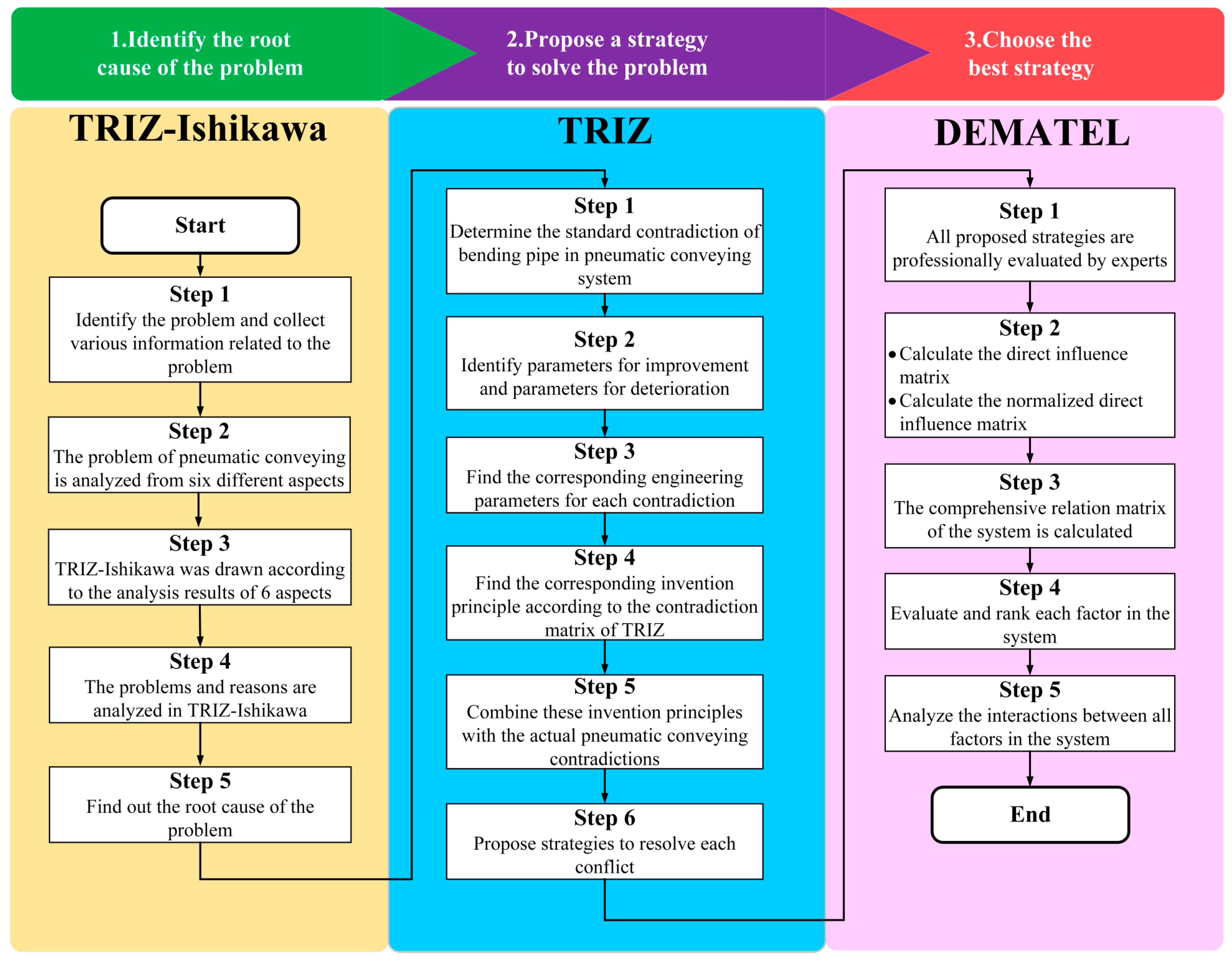
2.2. The TRIZ Technology Paradox
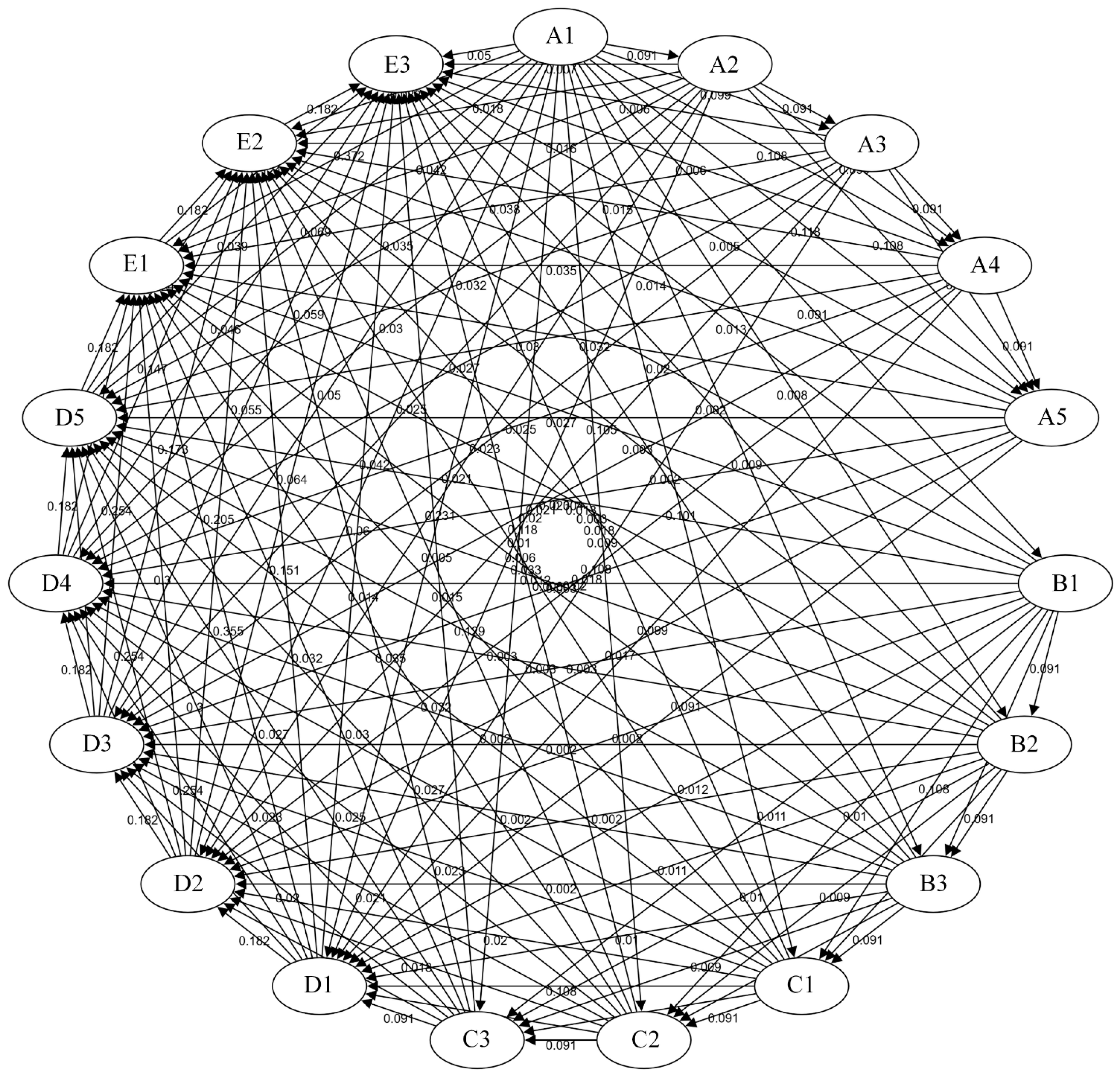
2.3. DEMATEL
3. Heuristic Reasoning for the Pneumatic Conveying Bend Challenge
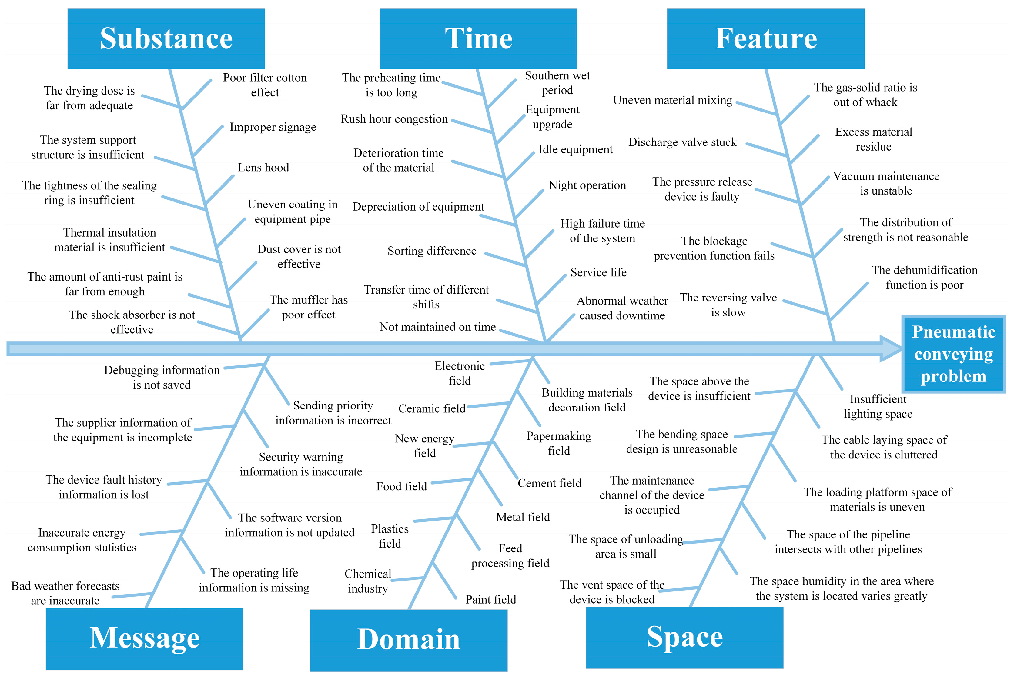
3.1. Determination of Root Cause Using TRIZ-Ishikawa
3.2. Contradictions in Pneumatic Conveying Bends
- Standard contradiction 1: Conveying efficiency and wear
- Standard contradiction 2: Bend strength and resistance
- Standard contradiction 3: Elbow obstruction and material qualities
- Standard contradiction 4: Bend radius and installation space
- Standard contradiction 5: Ease of maintenance and sealing
3.3. Innovative Approaches to Addressing the Difficulties of Pneumatic Conveying Bends
4. Analysis and Discussion of Results
5. Conclusions
- (1)
- By integrating the pneumatic conveying system using TRIZ-Ishikawa, we were able to analyze five key contradictions, such as conveying efficiency and wear, elbow strength and resistance, etc., and identify the root causes of problems in the system from six perspectives. For every conflict in the elbows of the pneumatic conveying system, we produced matching engineering characteristics and invention concepts using TRIZ technology, yielding 19 possible solutions. These solutions cover a wide range of topics, such as the use of unique materials, process optimization, and equipment upgrades.
- (2)
- The 19 solutions suggested by TRIZ were best chosen using the quantitative ranking method known as DEMATEL. The best ways to deal with the problems related to pneumatic conveying elbows were found to be “using quick-release flanges”, “pre-installing auxiliary air inlets at the most severely worn areas”, and “installing multiple identical airflow control devices at different locations along the pipeline.”
- (3)
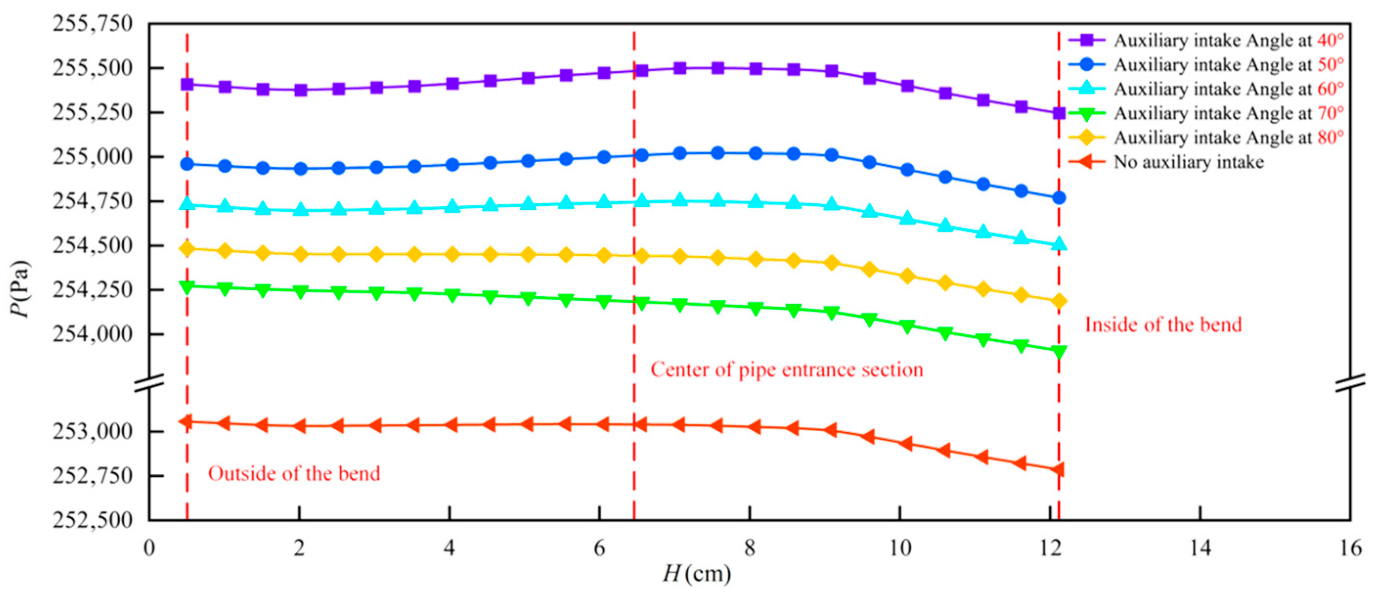
- The usefulness of the pre-added auxiliary air intake was confirmed by lowering the collision rate between the particle flow and the outside of the bent pipe wall by placing it where the bent pipe was most worn. The center axial velocity was raised by up to 27.3%, the maximum wear rate was decreased by 37%, and the average pressure drop was decreased by up to 9.5%. This established a methodological foundation for resolving related engineering problems and confirmed the efficacy of integrating TRIZ and DEMATEL in resolving complicated engineering system difficulties.
Author Contributions
Funding
Data Availability Statement
Conflicts of Interest
Abbreviations
| A | Direct impact matrix |
| aij | The degree of direct influence of factor i on j |
| B | Normalization directly affects the matrix. |
| bij | Indicates the element at the i-th row and j-th column position in matrix B |
| C | Comprehensive Impact Matrix |
| cij | Indicates the overall impact of factor Fi on factor Fj |
| I | unit matrix |
| Di | The degree of influence of various system factors |
| Fn | n factors within the system |
| X | Pipe length |
| Ri | The degree to which various system factors are affected |
| Pi | Centrality |
| Qi | Causality |
| A | Digital Strategy for addressing contradiction 1 |
| B | Digital Strategy for addressing contradiction 2 |
| C | Digital Strategy for addressing contradiction 3 |
| D | Digital Strategy for addressing contradiction 4 |
| E | Digital Strategy for addressing contradiction 5 |
| H | Radial height |
| P | Pipe pressure drop |
References
- Zhao, H.; Zhao, Y. CFD-DEM simulation of pneumatic conveying in a horizontal pipe. Powder Technol. 2020, 373, 58–72. [Google Scholar] [CrossRef]
- Meixuan, S.; Zhiqiang, W.; Jinjun, W.; Guofeng, L. Study on tribocharging of CaCO3 particles based on CFD-DEM gas-solid two-phase flow coupling. Powder Technol. 2021, 393, 610–618. [Google Scholar] [CrossRef]
- Ji, Y.; Hao, Y.; Yi, N.; Guan, T.; Gao, D. Particle flow regime in a swirling pneumatic conveying system. Powder Technol. 2022, 401, 117328. [Google Scholar] [CrossRef]
- Kalman, H.; Rawat, A. Flow regime chart for pneumatic conveying. Chem. Eng. Sci. 2020, 211, 115256. [Google Scholar] [CrossRef]
- Sun, S.; Yuan, Z.; Peng, Z.; Moghtaderi, B.; Doroodchi, E. Computational investigation of particle flow characteristics in pressurised dense phase pneumatic conveying systems. Powder Technol. 2018, 329, 241–251. [Google Scholar] [CrossRef]
- Du, H.; Lu, H.; Guo, X.; Liu, H. Pneumatic conveying characteristics in the rice husk powder industry and optimization of engineering process. Chem. Eng. Res. Des. 2025, 215, 157–169. [Google Scholar] [CrossRef]
- Alshahed, O.S.; Kaur, B.; Bradley, M.S.A.; Armour-Chelu, D. Data-driven system identification and model predictive control of pneumatic conveying using nonlinear dynamics analysis for optimised energy consumption. Powder Technol. 2025, 449, 120364. [Google Scholar] [CrossRef]
- Song, C.; Zhang, L.; Fang, S.; Zhao, Y.; Li, G.; Wang, Q. The CPFD approach was used to investigate the particle flow characteristics and auxiliary air inlet in an ash transfer pipe. Powder Technol. 2024, 435, 119410. [Google Scholar] [CrossRef]
- Zhang, L.; Song, C.; Fang, S.; Zhao, Y.; Li, G.; Wang, Q. Response surface method-based multi-objective optimization of auxiliary air intake in the ash transport tube. Particuology 2025, 98, 117–133. [Google Scholar] [CrossRef]
- de Freitas, A.G.; de Oliveira, V.F.; dos Santos, R.B.; Riascos, L.A.M.; Zou, R. Optimization method for pneumatic conveying parameters and energy consumption performance analysis of a compact blow tank. J. Press. Vessel Technol. 2022, 144, 064504. [Google Scholar] [CrossRef]
- Huang, F.; Kuang, S.; Zou, R.; Yu, A. Characterization of non-spherical particle tribocharging during horizontal pneumatic conveying. Appl. Math. Model. 2025, 140, 115894. [Google Scholar] [CrossRef]
- Ekmekci, I.; Nebati, E.E. Triz Methodology and applications. Procedia Comput. Sci. 2019, 158, 303–315. [Google Scholar] [CrossRef]
- Wang, J.; Zhang, Z.; Feng, L.; Lin, K.-Y.; Liu, P. Development of technology opportunity analysis based on technology landscape by extending technology elements with BERT and TRIZ. Technol. Forecast. Soc. Change 2023, 191, 122481. [Google Scholar] [CrossRef]
- Bourgeois-Bougrine, S.; Buisine, S.; Vandendriessche, C.; Glaveanu, V.; Lubart, T. Engineering students’ use of creativity and development tools in conceptual product design: What, when and how? Think. Ski. Creat. 2017, 24, 104–117. [Google Scholar] [CrossRef]
- Sheu, D.D.; Chiu, M.-C.; Cayard, D. The 7 pillars of TRIZ philosophies. Comput. Ind. Eng. 2020, 146, 106572. [Google Scholar] [CrossRef]
- Vicente-Gomila, J.M.; Artacho-Ramírez, M.A.; Ting, M.; Porter, A.L. Combining tech mining and semantic TRIZ for technology assessment: Dye-sensitized solar cell as a case. Technol. Forecast. Soc. Change 2021, 169, 120826. [Google Scholar] [CrossRef]
- Chou, J.-R. A TRIZ-based product-service design approach for developing innovative products. Comput. Ind. Eng. 2021, 161, 107608. [Google Scholar] [CrossRef]
- Khodadadi, A.; von Buelow, P. Design exploration by using a genetic algorithm and the Theory of Inventive Problem Solving (TRIZ). Autom. Constr. 2022, 141, 104354. [Google Scholar] [CrossRef]
- Shao, P.; Tan, R.; Peng, Q.; Liu, F.; Yang, W. Scenario-based anticipatory failure determination and patent technology inspiration for product innovation design. Technol. Forecast. Soc. Change 2024, 205, 123498. [Google Scholar] [CrossRef]
- Rau, H.; Wu, J.-J.; Procopio, K.M. Exploring green product design through TRIZ methodology and the use of green features. Comput. Ind. Eng. 2023, 180, 109252. [Google Scholar] [CrossRef]
- Adib, K.; Mazouzi, M.; Elyoussoufi, S. Investigation of annual trucks fatal accidents in El Hajeb province of Morocco using TRIZ-Ishikawa diagram. Heliyon 2024, 10, e26295. [Google Scholar] [CrossRef] [PubMed]
- Lee, C.-H.; Li, L.; Li, F.; Chen, C.-H. Requirement-driven evolution and strategy-enabled service design for new customized quick-response product order fulfillment process. Technol. Forecast. Soc. Change 2022, 176, 121464. [Google Scholar] [CrossRef]
- Biswas, S.; Ali, I.; Chakrabortty, R.K.; Turan, H.H.; Elsawah, S.; Ryan, M.J. Dynamic modeling for product family evolution combined with artificial neural network based forecasting model: A study of iPhone evolution. Technol. Forecast. Soc. Change 2022, 178, 121549. [Google Scholar] [CrossRef]
- Wang, L.; Zhao, D. Cross-domain function analysis and trend study in Chinese construction industry based on patent semantic analysis. Technol. Forecast. Soc. Change 2021, 162, 120331. [Google Scholar] [CrossRef]
- Qian, J.; Zhou, G.; He, W.; Cui, Y.; Deng, H. Optimization of teacher evaluation indicator system based on fuzzy-DEMATEL-BP. Heliyon 2024, 10, e34034. [Google Scholar] [CrossRef]
- Runtuk, J.K.; Ng, P.K.; Ooi, S.Y.; Vikaliana, R.; Iskandar, Y.A.; Abdillah, M.; Sukarno, I. Resolving contradictions in green supply chain management: A combined TRIZ and DEMATEL approach. Clean. Logist. Supply Chain. 2024, 13, 100195. [Google Scholar] [CrossRef]
- Guo, M.; Chen, M.; Yuan, L.; Zhang, Z.; Lv, J.; Cai, Z. Investigation of ship collision accident risk factors using BP-DEMATEL method based on HFACS-SCA. Reliab. Eng. Syst. Saf. 2025, 257, 110875. [Google Scholar] [CrossRef]
- Zheng, C.; Yang, W.; Jiang, X.; Lian, J.; Hu, D.; Yan, X.; Yan, L. A novel integrated Urban flood risk assessment approach coupling GeoDetector-Dematel and clustering method. J. Environ. Manag. 2024, 354, 120308. [Google Scholar] [CrossRef] [PubMed]
- Yuan, W.; Zhao, H.; Yang, X.; Han, T.; Chang, D. Toward dynamic rehabilitation management: A novel smart product-service system development approach based on fine-tuned large vision model and Fuzzy-Dematel. Adv. Eng. Inform. 2024, 62, 102616. [Google Scholar] [CrossRef]
- Zhao, S.; Hendalianpour, A.; Liu, P. Blockchain technology in omnichannel retailing: A novel fuzzy large-scale group-DEMATEL & Ordinal Priority approach. Expert. Syst. Appl. 2024, 249, 123485. [Google Scholar] [CrossRef]
- Yadegaridehkordi, E.; Hourmand, M.; Nilashi, M.; Shuib, L.; Ahani, A.; Ibrahim, O. Influence of big data adoption on manufacturing companies’ performance: An integrated DEMATEL-ANFIS approach. Technol. Forecast. Soc. Change 2018, 137, 199–210. [Google Scholar] [CrossRef]
- Fiorineschi, L.; Frillici, F.S.; Rotini, F.; Tomassini, M. Exploiting TRIZ Tools for enhancing systematic conceptual design activities. J. Eng. Des. 2018, 29, 259–290. [Google Scholar] [CrossRef]
- Wu, Y.; Zhou, F.; Kong, J. Innovative design approach for product design based on TRIZ, AD, fuzzy and Grey relational analysis. Comput. Ind. Eng. 2020, 140, 106276. [Google Scholar] [CrossRef]
- Liu, Q.; Chen, X. Evaluating ergonomic requirements of graphical user interface: A DEMATEL method integrating linguistic Pythagorean fuzzy rough numbers. Appl. Soft Comput. 2024, 167, 112465. [Google Scholar] [CrossRef]
- Delgado-Maciel, J.; Cortés-Robles, G.; Sánchez-Ramírez, C.; García-Alcaraz, J.; Méndez-Contreras, J.M. The evaluation of conceptual design through dynamic simulation: A proposal based on TRIZ and system Dynamics. Comput. Ind. Eng. 2020, 149, 106785. [Google Scholar] [CrossRef]
- Aguilar-Lasserre, A.A.; Torres-Sánchez, V.E.; Fernández-Lambert, G.; Azzaro-Pantel, C.; Cortes-Robles, G.; Román-del Valle, M.A. Functional optimization of a Persian lime packing using TRIZ and multi-objective genetic algorithms. Comput. Ind. Eng. 2020, 139, 105558. [Google Scholar] [CrossRef]
- Chang, Y.-S.; Chien, Y.-H.; Yu, K.-C.; Chu, Y.-H.; Chen, M.Y. Effect of TRIZ on the creativity of engineering students. Think. Ski. Creat. 2016, 19, 112–122. [Google Scholar] [CrossRef]
- Wei, D.; Liu, H.; Shi, K. What are the key barriers for the further development of shale gas in China? A grey-DEMATEL approach. Energy Rep. 2019, 5, 298–304. [Google Scholar] [CrossRef]
- Zhang, L.; Sun, X.; Xue, H. Identifying critical risks in Sponge City PPP projects using DEMATEL method: A case study of China. J. Clean. Prod. 2019, 226, 949–958. [Google Scholar] [CrossRef]
- Hsu, W.-C.J.; Liou, J.J.H.; Lo, H.-W. A group decision-making approach for exploring trends in the development of the healthcare industry in Taiwan. Decis. Support. Syst. 2021, 141, 113447. [Google Scholar] [CrossRef]
- Kumar, A.; Dixit, G. An analysis of barriers affecting the implementation of e-waste management practices in India: A novel ISM-DEMATEL approach. Sustain. Prod. Consum. 2018, 14, 36–52. [Google Scholar] [CrossRef]
- Dumas, D.; Schmidt, L.C.; Alexander, P.A. Predicting creative problem solving in engineering design. Think. Ski. Creat. 2016, 21, 50–66. [Google Scholar] [CrossRef]
- Zhao, Y.; Li, Z.; Li, W.; Huang, Z. Developing an innovative design model for Xinjiang brocades based on design thinking. Think. Ski. Creat. 2025, 56, 101780. [Google Scholar] [CrossRef]
- Sharma, M.; Joshi, S.; Kumar, A. Assessing enablers of e-waste management in circular economy using DEMATEL method: An Indian perspective. Environ. Sci. Pollut. Res. 2020, 27, 13325–13338. [Google Scholar] [CrossRef]
- Zhao, G.; Irfan Ahmed, R.; Ahmad, N.; Yan, C.; Usmani, M.S. Prioritizing critical success factors for sustainable energy sector in China: A DEMATEL approach. Energy Strategy Rev. 2021, 35, 100635. [Google Scholar] [CrossRef]
- Gupta, N.; Vrat, P.; Ojha, R. Prioritizing enablers for service quality in healthcare sector—A DEMATEL approach. J. Health Organ. Manag. 2022, 36, 633–649. [Google Scholar] [CrossRef] [PubMed]




| Engineering Parameters | ||
|---|---|---|
| 1. Weight of moving objects | 14. Strength | 27. Reliability |
| 2. Weight of a stationary object | 15. Persistence of moving objects | 28. Accuracy of measurements |
| 3. Length of moving object | 16. Persistence of stationary objects | 29. Manufacturing accuracy |
| 4. Length of stationary object | 17. Temperature | 30. Harmful factors acting on objects |
| 5. Area of the moving object | 18. Luminance | 31. Harmful side effects |
| 6. Area of a stationary object | 19. Energy for moving objects | 32. Manufacturable |
| 7. Volume of moving objects | 20. Energy for non-mobile objects | 33. Ease of use |
| 8. Volume of a stationary object | 21. Power (output) | 34. Restorative |
| 9. Speed | 22. Waste of energy | 35. Adaptation |
| 10. Force | 23. Material waste | 36. Complexity of equipment |
| 11. Tension/Pressure | 24. Loss of information | 37. Complexity of control |
| 12. Geometry | 25. Waste of time | 38. Degree of automation |
| 13. Stability of the objects | 26. Total amount of substance | 39. Capacity/productivity |
| Principles of Invention | ||
|---|---|---|
| 1. Splitting | 15. Dynamic | 29. Pneumatic or hydraulic |
| 2. Extraction | 16. Partial or excessive movement | 30. Elastic membrane or film |
| 3. Principle of Localized Mass | 17. Change to a new dimension | 31. Porous materials |
| 4. Asymmetry | 18. Mechanical vibration | 32. Color |
| 5. Merger/combination | 19. Periodic movements | 33. Homogeneity/conformity |
| 6. Versatility/multifunctionality | 20. Continuity of effective movement | 34. Discarded and recycled parts |
| 7. Interleave | 21. Rapid movements | 35. Performance Transformation |
| 8. Principle of weight compensation | 22. Turning harm into good | 36. Phase Change |
| 9. Pre-emptive counteraction | 23. Giving back | 37. Thermal expansion |
| 10. Pre-action | 24. Mediation | 38. Strong oxidation |
| 11. Precautionary | 25. Self-help | 39. Principle of Inert Environment |
| 12. Isotropy | 26. Reproduction | 40. Composites |
| 13. Reverse Action | 27. Replacement by cheaper and shorter life | |
| 14. Curve Surfacing | 28. Principle of mechanical system substitution | |
| Relationships of Influence | Not Have | Slightly Less Than | Center | Unyielding | Extremely Strong |
|---|---|---|---|---|---|
| Scale | 0 | 1 | 2 | 3 | 4 |
| Standard Contradiction | Gestion | Improvement (I) and Worsening (W) | Engineering Parameters |
|---|---|---|---|
| Standard contradiction 1 | Improvement of conveying efficiency of pneumatic conveying | I: Increased conveying efficiency W: Increased wear and tear | 9. Speed 14. Strength |
| Standard contradiction 2 | Strengthening of curves | I: Increased strength of the bend W: Increase in local resistance at the bend | 14. Strength 10. Force |
| Standard contradiction 3 | Adjustment to the properties of the material to prevent elbow blockage | I: Adaptation to material properties reduces clogging W: Increased costs | 35. Adaptation 26. Total amount of substance |
| Standard contradiction 4 | Optimizes bend radius while meeting installation space requirements | I: Reduced installation space after optimizing bend radius W: Impact on conveying performance | 5. Area of moving objects 13. Stability of the objects |
| Standard contradiction 5 | Improving the simplicity of bend maintenance | I: Increased ease of maintenance W: Poor sealing leads to loss of pneumatic conveying particles | 33. Ease of use 23. Material waste |
| Standard Contradiction | Engineering Parameters | Principles of Invention |
|---|---|---|
| Standard contradiction 1 | Improvement (I): 9. Speed Worsening (W): 14. Strength | 8. Principle of weight compensation 3. Principle of localized quality 26. Principle of Reproduction 14. Curve Surfacing Principle |
| Standard contradiction 2 | Improvement (I):14. Strength Worsening (W): 10. Force | 18. Principle of mechanical vibration 10. Pre-action principle 3. Principle of Localized Mass 14. Curve Surfacing Principle |
| Standard contradiction 3 | Improvement (I): 35. Adaptation Worsening (W): 26. Total amount of substance | 3. Principle of localized quality 35. Performance Transformation Principle 15. Dynamic principle |
| Standard contradiction 4 | Improvement (I): 5. Area of moving objects Worsening (W): 13. Stability of the object | 11. Precautionary principle 2. Extraction Principle 13. Reverse Action Principle 39. Principle of Inert Environment |
| Standard contradiction 5 | Improvement (I): 33. Ease of use Worsening (W): 23. Material waste | 28. Principle of mechanical system substitution 32. Color principle 2. Extraction Principle 24. Mediation Principle |
| Contradictions Faced | Principles of Invention | Principles of Innovation Derived from Pneumatic Conveying Heuristic Reasoning |
|---|---|---|
| High-speed conveying improves conveying efficiency, but it also increases friction between the material and the pipe’s inner wall. | 8. Principle of weight compensation 3. Principle of localized quality 26. Principle of Reproduction 14. Curve Surfacing Principle | A1. Installing many airflow regulators that are identical at different pipeline sites. A2. Putting an appropriate amount of lubricant on the area that is causing the most friction. A3. Use localized cooling techniques in specific pipe sections that are subject to high levels of wear and tear in order to lessen the worsening of material characteristics and increased wear caused by high temperatures. A4. Reproduction of the wear-resistant material coating: covering the entire pipe’s inner wall with several layers of the same material coating. A5. Use of flexible, curving tubing, which allow for some deformation as a cushioning effect. |
| Boost the bend’s strength, but do so at the expense of increased localized resistance. | 18. Principle of mechanical vibration 10. Pre-action principle 3. Principle of Localized Mass 14. Curve Surfacing Principle | B1. At the bends, vibrators are positioned to produce resistance in the pipe, which increases amplitude. B2. By enabling materials to enter the bent pipe smoothly, pre-buffer silo placement reduces the impact’s local resistance. B3. Localized use of high-efficiency bent pipe designs with high-efficiency infusion reduces the advantages of resistance. |
| Specialized designs and expensive materials are used to lessen congestion, albeit this may lead to increased costs. | 3. Principle of localized quality 35. Performance Transformation Principle 15. Dynamic principle | C1. Turn manual monitoring into intelligent regulation and monitoring by putting in place an intelligent control system. C2. Replace conventional thin-phase pneumatic conveying with dense-phase or pulse pneumatic conveying. C3. Installing sensors allows for dynamic, real-time material property monitoring. |
| Optimize bend radii to minimize installation space, but conveyance performance may decrease as a result. | 11. Precautionary principle 2. Extraction Principle 13. Reverse Action Principle 39. Principle of Inert Environment | D1. At the most abrasive location, an auxiliary air inlet is already constructed, and the airflow provides secondary energy to move the particles forward. D2. Pre-simulate and examine bends of various radii using fluid dynamics simulation software. D3. Finding the causes of pressure loss and improving bend structures to lessen pressure loss from changing the radius D4. Make the switch to a flexible connection from a conventional, hard one. D5. By introducing nitrogen and other inert gases to create an inert atmosphere that prevents raw materials from oxidizing and deteriorating, you can lower transport performance. |
| To make maintenance easier, the piping system might be simplified; however, this may result in inadequate sealing and particle loss. | 28. Principle of mechanical system substitution 32. Color principle 2. Extraction Principle 24. Mediation Principle | E1. Use quick-release flanges and make sure sealing gaskets are optimized to preserve sealing. E2. Apply fluorescent color coating to the sealing area, causing the particles to change color when leaking. E3. Install intermediate barriers with air curtain sealing in regions where pipeline leaks are common. |
| A1 | A2 | A3 | A4 | A5 | B1 | B2 | B3 | C1 | ||
| A1 | 0 | 0.091 | 0.099 | 0.108 | 0.118 | 0.091 | 0.008 | 0.009 | 0.101 | |
| A2 | 0 | 0 | 0.091 | 0.099 | 0.108 | 0 | 0 | 0 | 0 | |
| A3 | 0 | 0 | 0 | 0.091 | 0.099 | 0 | 0 | 0 | 0 | |
| A4 | 0 | 0 | 0 | 0 | 0.091 | 0 | 0 | 0 | 0 | |
| A5 | 0 | 0 | 0 | 0 | 0 | 0 | 0 | 0 | 0 | |
| B1 | 0 | 0 | 0 | 0 | 0 | 0 | 0.091 | 0.099 | 0.108 | |
| B2 | 0 | 0 | 0 | 0 | 0 | 0 | 0 | 0.091 | 0.099 | |
| B3 | 0 | 0 | 0 | 0 | 0 | 0 | 0 | 0 | 0.091 | |
| C1 | 0 | 0 | 0 | 0 | 0 | 0 | 0 | 0 | 0 | |
| C2 | 0 | 0 | 0 | 0 | 0 | 0 | 0 | 0 | 0 | |
| C3 | 0 | 0 | 0 | 0 | 0 | 0 | 0 | 0 | 0 | |
| D1 | 0 | 0 | 0 | 0 | 0 | 0 | 0 | 0 | 0 | |
| D2 | 0 | 0 | 0 | 0 | 0 | 0 | 0 | 0 | 0 | |
| D3 | 0 | 0 | 0 | 0 | 0 | 0 | 0 | 0 | 0 | |
| D4 | 0 | 0 | 0 | 0 | 0 | 0 | 0 | 0 | 0 | |
| D5 | 0 | 0 | 0 | 0 | 0 | 0 | 0 | 0 | 0 | |
| E1 | 0 | 0 | 0 | 0 | 0 | 0 | 0 | 0 | 0 | |
| E2 | 0 | 0 | 0 | 0 | 0 | 0 | 0 | 0 | 0 | |
| E3 | 0 | 0 | 0 | 0 | 0 | 0 | 0 | 0 | 0 | |
| C2 | C3 | D1 | D2 | D3 | E1 | E2 | E3 | E4 | E5 | |
| A1 | 0.009 | 0.01 | 0.231 | 0.042 | 0.05 | 0.059 | 0.069 | 0.372 | 0.088 | 0.05 |
| A2 | 0 | 0 | 0.118 | 0.021 | 0.025 | 0.03 | 0.035 | 0.042 | 0.018 | 0.007 |
| A3 | 0 | 0 | 0.108 | 0.02 | 0.023 | 0.027 | 0.032 | 0.038 | 0.016 | 0.006 |
| A4 | 0 | 0 | 0.099 | 0.018 | 0.021 | 0.025 | 0.03 | 0.035 | 0.015 | 0.006 |
| A5 | 0 | 0 | 0.091 | 0.017 | 0.02 | 0.023 | 0.027 | 0.032 | 0.014 | 0.005 |
| B1 | 0.01 | 0.011 | 0.012 | 0.002 | 0.003 | 0.003 | 0.004 | 0.105 | 0.02 | 0.013 |
| B2 | 0.009 | 0.01 | 0.011 | 0.002 | 0.002 | 0.003 | 0.003 | 0.013 | 0.003 | 0.002 |
| B3 | 0.008 | 0.009 | 0.01 | 0.002 | 0.002 | 0.002 | 0.003 | 0.012 | 0.003 | 0.002 |
| C1 | 0.091 | 0.099 | 0.108 | 0.02 | 0.023 | 0.027 | 0.032 | 0.129 | 0.033 | 0.018 |
| C2 | 0 | 0.091 | 0.099 | 0.018 | 0.021 | 0.025 | 0.03 | 0.035 | 0.015 | 0.006 |
| C3 | 0 | 0 | 0.091 | 0.017 | 0.02 | 0.023 | 0.027 | 0.032 | 0.014 | 0.005 |
| D1 | 0 | 0 | 0 | 0.182 | 0.215 | 0.254 | 0.3 | 0.355 | 0.151 | 0.06 |
| D2 | 0 | 0 | 0 | 0 | 0.182 | 0.215 | 0.254 | 0.3 | 0.205 | 0.064 |
| D3 | 0 | 0 | 0 | 0 | 0 | 0.182 | 0.215 | 0.254 | 0.173 | 0.055 |
| D4 | 0 | 0 | 0 | 0 | 0 | 0 | 0.182 | 0.215 | 0.147 | 0.046 |
| D5 | 0 | 0 | 0 | 0 | 0 | 0 | 0 | 0.182 | 0.124 | 0.039 |
| E1 | 0 | 0 | 0 | 0 | 0 | 0 | 0 | 0 | 0.182 | 0.124 |
| E2 | 0 | 0 | 0 | 0 | 0 | 0 | 0 | 0 | 0 | 0.182 |
| E3 | 0 | 0 | 0 | 0 | 0 | 0 | 0 | 0 | 0 | 0 |
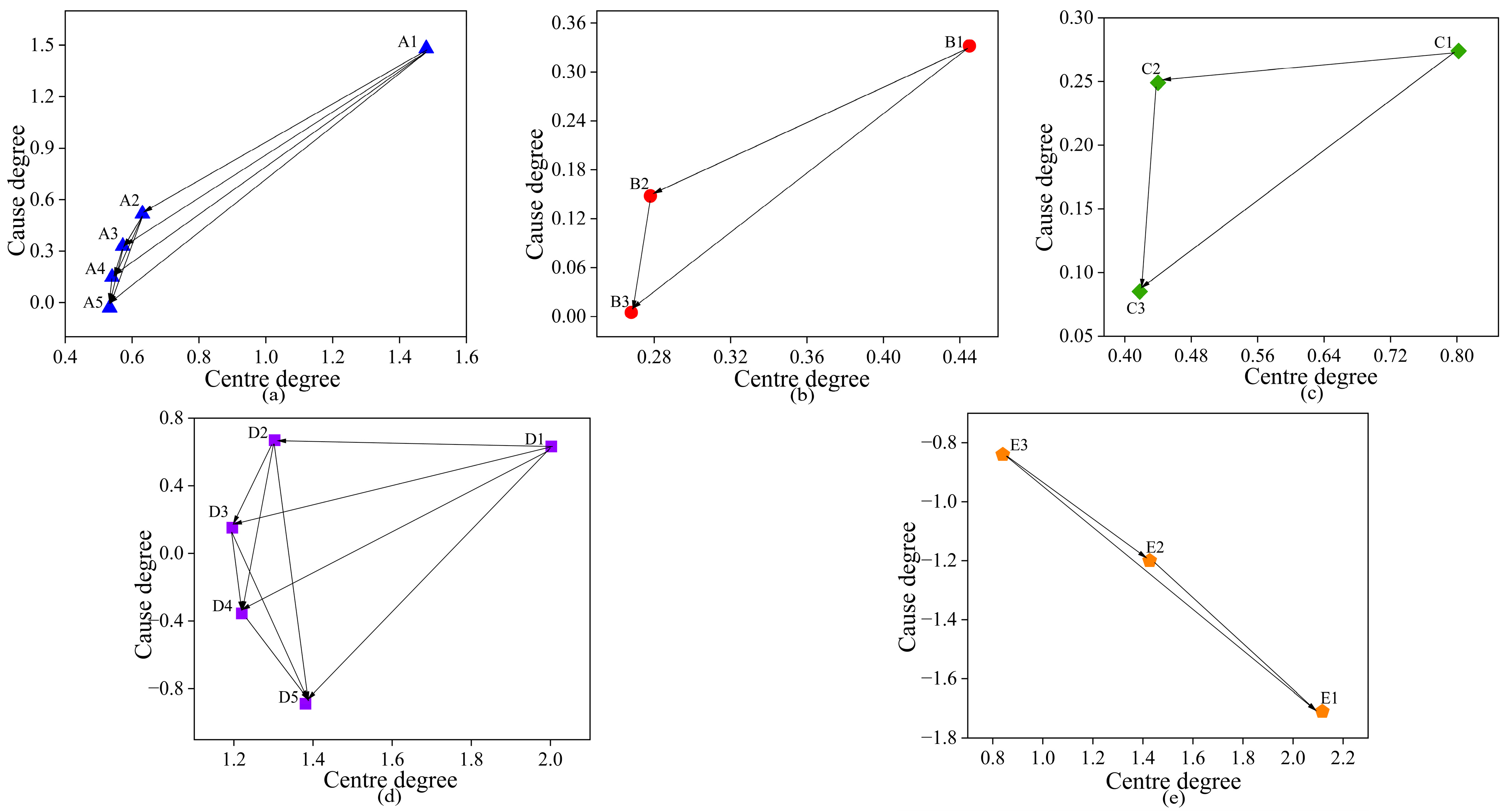
| Degree of Influence Di | Influenced Degree Ri | Centrality Pi | Reason Degree Qi | Wights | Order of Centrality | Factor Attributes | |
|---|---|---|---|---|---|---|---|
| A1 | 1.48 | 0 | 1.48 | 1.48 | 0.083 | 3 | Contributory factor |
| A2 | 0.574 | 0.057 | 0.631 | 0.517 | 0.035 | 11 | Contributory factor |
| A3 | 0.45 | 0.122 | 0.572 | 0.329 | 0.032 | 12 | Contributory factor |
| A4 | 0.344 | 0.196 | 0.54 | 0.148 | 0.03 | 13 | Contributory factor |
| A5 | 0.252 | 0.282 | 0.533 | −0.03 | 0.03 | 14 | Outcome factor |
| B1 | 0.389 | 0.057 | 0.445 | 0.332 | 0.025 | 15 | Contributory factor |
| B2 | 0.213 | 0.065 | 0.278 | 0.148 | 0.016 | 18 | Contributory factor |
| B3 | 0.136 | 0.131 | 0.268 | 0.005 | 0.015 | 19 | Contributory factor |
| C1 | 0.538 | 0.264 | 0.802 | 0.274 | 0.045 | 10 | Contributory factor |
| C2 | 0.344 | 0.095 | 0.44 | 0.249 | 0.025 | 16 | Contributory factor |
| C3 | 0.252 | 0.167 | 0.418 | 0.085 | 0.023 | 17 | Contributory factor |
| D1 | 1.318 | 0.685 | 2.002 | 0.633 | 0.112 | 2 | Contributory factor |
| D2 | 0.986 | 0.316 | 1.303 | 0.67 | 0.073 | 6 | Contributory factor |
| D3 | 0.674 | 0.522 | 1.196 | 0.152 | 0.067 | 8 | Contributory factor |
| D4 | 0.433 | 0.788 | 1.222 | −0.355 | 0.068 | 7 | Outcome factor |
| D5 | 0.247 | 1.134 | 1.381 | −0.887 | 0.077 | 4 | Outcome factor |
| E1 | 0.204 | 1.914 | 2.117 | −1.71 | 0.118 | 1 | Outcome factor |
| E2 | 0.113 | 1.314 | 1.427 | −1.2 | 0.08 | 5 | Outcome factor |
| E3 | 0 | 0.84 | 0.84 | −0.84 | 0.047 | 9 | Outcome factor |
| Rankings | Strategy | Conflicting Views | Response |
|---|---|---|---|
| 1 | E1 | Ease of maintenance and sealing | Use quick release flanges and make sure sealing gaskets are optimized to preserve sealing. |
| 2 | D1 | Installation space and bend radius | At the most abrasive location, an auxiliary air inlet is already constructed, and the airflow provides secondary energy to move the particles forward. |
| 3 | A1 | Conveying efficiency and wear | Installing many airflow regulators that are identical at different pipeline sites. |
| 4 | D5 | Installation space and bend radius | By introducing nitrogen and other inert gases to create an inert atmosphere that prevents raw materials from oxidizing and deteriorating, you can lower transport performance. |
| 5 | E2 | Ease of maintenance and sealing | Apply fluorescent color coating to the sealing area, causing the particles to change color when leaking. |
| 6 | D2 | Installation space and bend radius | Pre-simulate and examine bends of various radii using fluid dynamics simulation software. |
Disclaimer/Publisher’s Note: The statements, opinions and data contained in all publications are solely those of the individual author(s) and contributor(s) and not of MDPI and/or the editor(s). MDPI and/or the editor(s) disclaim responsibility for any injury to people or property resulting from any ideas, methods, instructions or products referred to in the content. |
© 2025 by the authors. Licensee MDPI, Basel, Switzerland. This article is an open access article distributed under the terms and conditions of the Creative Commons Attribution (CC BY) license (https://creativecommons.org/licenses/by/4.0/).
Share and Cite
Su, J.; Zhang, L.; Ma, X.; Xu, X.; Jia, Y.; Pan, Y.; Zhang, L.; Song, C.; Jiang, T. Diagnosis and Solution of Pneumatic Conveying Bend Problems: Application of TRIZ-DEMATEL Coupling Technology. Powders 2025, 4, 27. https://doi.org/10.3390/powders4040027
Su J, Zhang L, Ma X, Xu X, Jia Y, Pan Y, Zhang L, Song C, Jiang T. Diagnosis and Solution of Pneumatic Conveying Bend Problems: Application of TRIZ-DEMATEL Coupling Technology. Powders. 2025; 4(4):27. https://doi.org/10.3390/powders4040027
Chicago/Turabian StyleSu, Jianming, Lidong Zhang, Xiaoyang Ma, Xinyu Xu, Yuhan Jia, Yuhao Pan, Lifeng Zhang, Changpeng Song, and Tieliu Jiang. 2025. "Diagnosis and Solution of Pneumatic Conveying Bend Problems: Application of TRIZ-DEMATEL Coupling Technology" Powders 4, no. 4: 27. https://doi.org/10.3390/powders4040027
APA StyleSu, J., Zhang, L., Ma, X., Xu, X., Jia, Y., Pan, Y., Zhang, L., Song, C., & Jiang, T. (2025). Diagnosis and Solution of Pneumatic Conveying Bend Problems: Application of TRIZ-DEMATEL Coupling Technology. Powders, 4(4), 27. https://doi.org/10.3390/powders4040027


