Abstract
It is shown in the literature that wind turbine designs with different load distributions have different wake features. To systematically study how different load distributions affect turbine wakes, a method for designing variants of blades with different radial load distributions, but with approximately the same power () or thrust coefficient (), is needed. In this work, an inverse design method based on the blade element momentum method and the multi-dimensional Newton’s method, with the normal and tangential force coefficients as the design objective and iterations for satisfying the or constraint, is developed. The proposed method is validated using the two-bladed small-scale NREL phase VI S809 wind turbine blade design and the three-bladed utility-scale NREL 5 MW wind turbine blade design. Four variants of the NREL 5 MW wind turbine, i.e., the Root-CP, Tip-CP, Root-CT, and Tip-CT designs, which represent the variants of the original design (NREL-Ori) with a higher load near the blade root and tip regions with approximately the same power coefficient () or thrust coefficient () as that of the NREL-Ori design, respectively, are then designed using the proposed method. At last, the flapwise blade bending moment and the power coefficients from different variants of the NREL 5 MW turbine are compared for different tip speed ratios, showing that the “Root” designs are featured by a wider chord near the root, lower blade bending moment, and higher power coefficients for tip-speed ratios greater than nine.
1. Introduction
Driven by the increasing demand for energy systems with low or net-zero carbon emission to slow climate change, wind energy is becoming one of the fastest growing renewable energies [1,2,3,4]. Innovative designs of blades can increase the performance of wind turbines and decrease the wind energy capital expenditures. Moreover, recent studies show that the blade design can also affect the dynamics of wind turbine wakes [5,6]. This work is devoted to develop a blade design method for designing blades with certain radial distributions of load coefficients.
The methods for designing wind turbine blades can be classified into two categories: (i) the direct approach which is also called the design-by-analysis approach, and (ii) the inverse design approach. To design a blade, a wind turbine performance solver is required, such as the blade element momentum (BEM) method [7,8,9,10], the vortex line method (VLM) [11,12,13,14], and the computational fluid dynamic method [15,16,17,18,19]. The BEM method [7,9] is the one routinely used because of its reasonable accuracy and low computational cost. In the BEM method, the performance of the rotor is computed using the one-dimensional momentum method with aerodynamics forces at each radial location computed using the blade element approach with tables of blade twist and chord distributions, airfoil type distribution, and lift and drag coefficients for different angles of attack and Reynolds numbers. The VLM represents the wind turbine blade as a series of bound vortex and trailing vortices, which can model the blade aerodynamics more accurately, but is more computationally expensive when compared with the BEM method. The CFD method, including large eddy simulation (LES) and Reynolds-averaged Navier Stokes (RANS) approaches, especially when coupled with the non-boundary conforming method [20,21,22,23], can simulate the blade aerodynamics in a more accurate and efficient way, however requires significantly high computational cost especially for the DNS and LES approaches, which are not yet feasible for blade design in engineering applications.
In the aforementioned blade design approaches, the direct approach, which prescribes and adjusts the blade geometry, and then determines the performance through analysis [24,25], is easy to implement, however its performance depends on the experience of the user and may become time consuming. In practice, an optimization method is often employed with a specific objective function when designing a wind turbine blade [26]. Chattot [11] used the Lagrange multiplier technique to determine distributions of blade twist and chord. Juan Méndez and David Greiner [27] adopted the genetic algorithms to optimize the wind blade chord and twist distributions with the objective of maximizing the power output. Since the direct approach is time consuming with no guarantee of achieving the desired optimum values, an inverse design approach was developed by Selig and Tangler [24]. They combined the multi-dimensional Newton’s iteration method with the BEM method to design the blade twist and chord distributions with the desired distributions of the lift coefficient and the axial induction factor along the blade radial directions. To account for the three-dimensional blade features, Lee [28] combined the multi-dimensional Newton’s iteration method with a vortex line method to design the blade geometry. Wind turbine wakes are closely related with the force distribution along the blade. Instead of using the lift coefficient and the axial induction factor as the input in the inverse design method [24,28], in this work, we employ the normal and tangential force coefficients as the input, which are more convenient for designing blades with different load distributions.
To systematically study how the blade design affects the wake evolution, blade designs with different load distributions have to be developed. It will be convenient if one can obtain such blade designs from the existing wind turbine blade design. To achieve this objective, in this paper, we develop an inverse method based on the multi-dimensional Newton’s iteration method and the BEM method, and design four variants of the NREL 5 MW wind turbines [29,30], i.e., (i) the Root-CP, (ii) the Tip-CP, (iii) the Root-CT, and (iv) the Tip-CT wind turbines, which represent the designs with a higher load near the blade root and tip with approximately the same power coefficient () or the thrust coefficient (), respectively.
The novelty of the proposed method underpins on the design objectives, i.e., variants of blade designs with different radial distributions of normal and tangential load coefficients with approximately the same power or thrust coefficient, which are the radial distributions of the lift coefficient and axial induction factor in the methods developed by Selig and Tangler [24] and Lee [28]. The axial induction factor, a quantity describing the momentum loss as the air flows through the rotor, is not directly related with the forces exerted on the blade. For the simulations with the rotor parameterized using the actuator disk [15], which employs the axial induction factor as the input, therefore using the axial induction factor as the design objective is a right choice. For the actuator line/surface simulations [17,31], where each blade is modeled using distributed forces, directly using the load coefficients as the design objectives is obviously better suited. One drawback of the method developed in this work is the low fidelity of the employed blade element momentum method for modeling the aerodynamics of wind turbines, which depends on the quality of the lift and drag coefficients as well as the corrections for the three-dimensional effect and the tip loss correction [9].
The rest of the paper is structured as follows. The inverse design method is introduced in Section 2. In Section 3, the inverse method is validated for the two-bladed NREL phase VI S809 wind turbine and the three-blade NREL 5 MW wind turbine. Then, four variants of the NREL 5 MW turbine are designed and presented in Section 4. At last, conclusions are drawn in Section 5.
2. The Inverse Method for Blade Design
In this section, the inverse method for designing blades with given distributions of force coefficients is described. The present inverse design method employs the desired normal force coefficient and tangential force coefficient as the input, and gives the radial distributions of the chord and twist as the output. Using the multi-dimensional Newton’s method, the radial distributions of and are computed as follows:
where:
and J is the Jacobian matrix formed as follows:
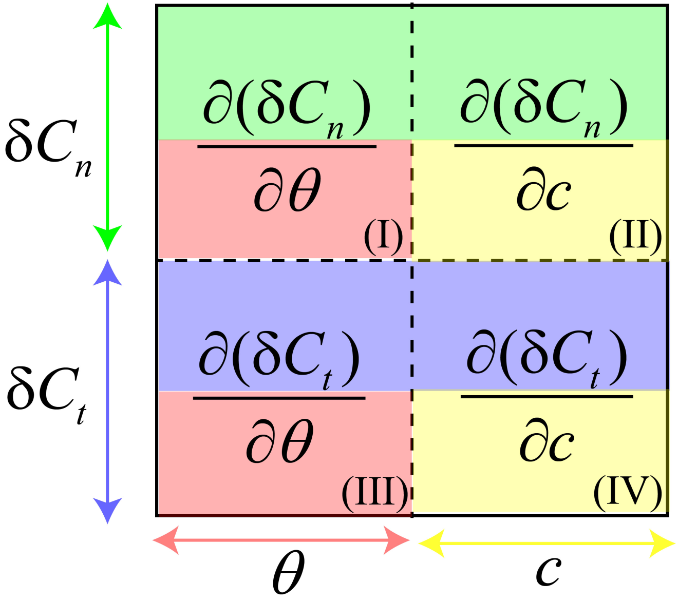
In the above equations, n denotes the number of elements along the blade in the radial direction, and represents the difference between the computed value and the desired value. To get a better idea on the structure of the Jacobian matrix, a schematic is shown in Figure 1. As seen, in the first row, the first (I) and second quadrants (II) describe the rate of change of the normal force coefficient () to the change of the twist angle () and the change of the blade chord (c) at each element, respectively. Meanwhile, in the second row, the third (III) and fourth quadrants (IV) describe the rate of change of the tangential force coefficient () to the change of the twist angle () and the change of the blade chord (c) at each radial element, respectively.
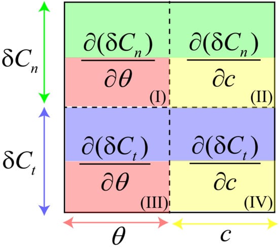
Figure 1.
Schematic of the Jacobian matrix.
The values of Jacobian J are calculated using a second-order finite difference scheme. In the Jacobian J, is the difference between the values of and calculated by the BEM method and the desired values of and , respectively. Details on the implementation of the BEM method can be found in Appendix A. For example, is computed as follows:
where is the at the first element when is the variable. A second-order, finite central difference scheme is used to compute the Jacobian matrix. For example, is computed by:
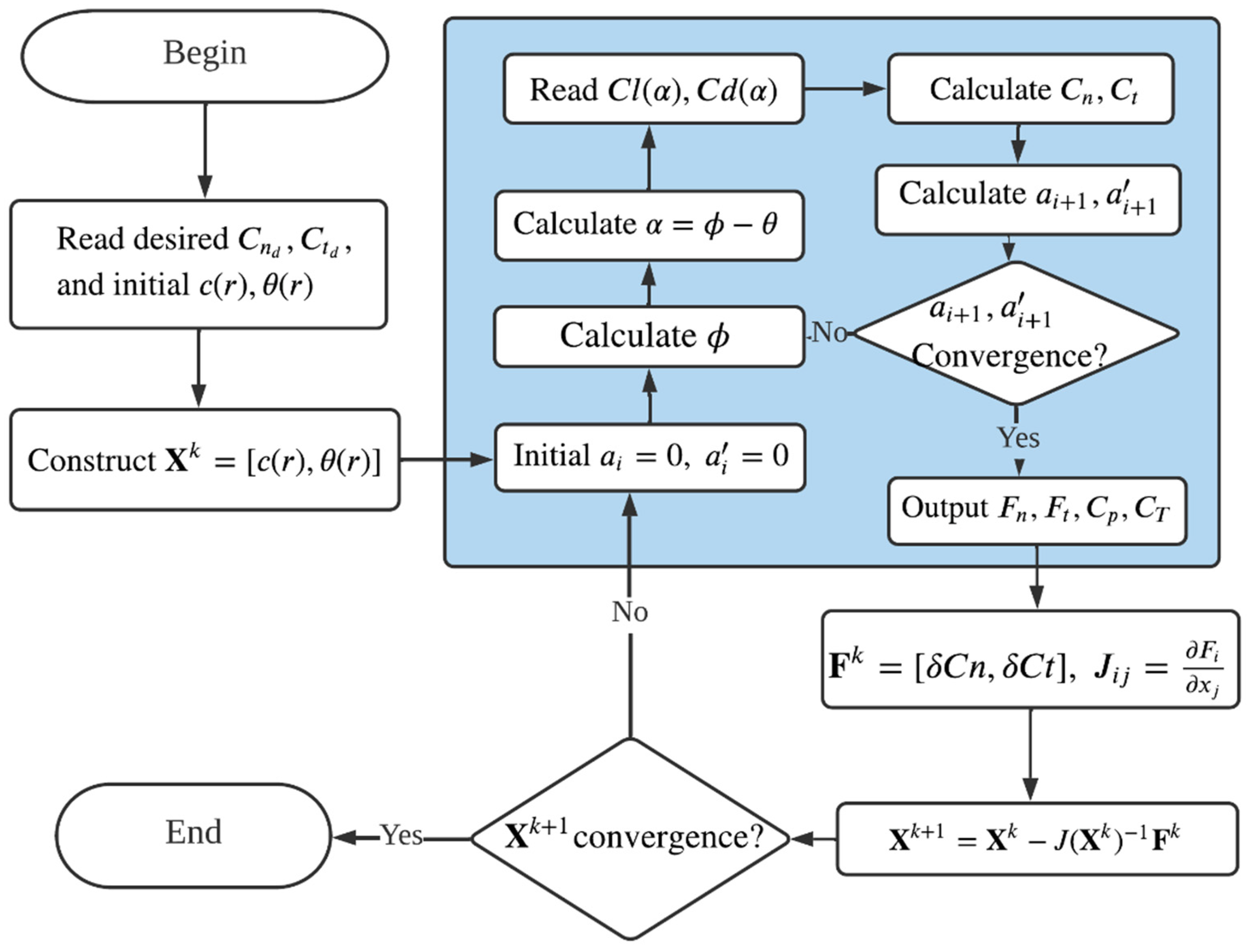
A flowchart for the inverse design method is shown in Figure 2. At first, the desired wind turbine performance and are read from the input files, meanwhile the initial values of the blade geometrical parameters ( and ) are assigned to . Then the BEM code (shown in blue in Figure 2) is performed to provide the computed aerodynamic behavior ( and ). Once and are obtained, the linear algebraic equation in Equation (1) is solved to obtain new values of X. At this step, the -norm is used to check the convergence of the solutions, which is defined as:
where i denotes the index of the blade element at each radial position and k is the number of Newton’s iteration. In our study, is set as the convergence criteria of the -norm, which is found to be sufficient to guarantee the accuracy and computational efficiency.

Figure 2.
Flowchart for the inverse design method, in which the BEM calculation is shown in the blue box.
Having approximately the same or will enable a fair comparison among the blade designs with different force distributions. However, this cannot be directly satisfied when we design the blade with the given normal and tangential force coefficients as and being dependent on the chord at different radial locations as well, which is the output when designing a blade. In this work, we solve this problem via an iterative way. Specifically, we multiply the load distribution with a coefficient and manually tune its value based on the and of the obtained blade design.
3. Validations
In this section, the proposed method is validated with the two-bladed NREL phase VI S809 [32,33,34] wind turbine and three-bladed NREL 5 MW [29,30] wind turbine. The parameters of the two turbines are shown in Table 1, the tip speed ratio (, TSR) is set to be 8, which is defined as the ratio between the tangential speed at the blade tip () and the incoming wind speed . For both cases, 200 elements are used for discretizing the blade. Note that the blade root region of the cylinder shape is not designed with starting position at 1.51 m and 9.7 m along the blade radial directions for NREL S809 and NREL 5 MW wind turbines, respectively. In the case of the two-bladed S809 wind turbine, the 2D polar data of this airfoil at were obtained from XFOIL [35].

Table 1.
Wind turbine parameters.
Firstly, with the reference data of the twist and chord for both turbines, the BEM simulations are carried out to obtain the and , which are used as the input data for the validation of the proposed method. By prescribing the distributions of and , the distributions of the blade twist () and chord (c) are designed using the proposed method with the initial distributions of and c off the actual data. The and c designed using the proposed method are then compared with the reference data of the two-bladed NREL phase VI S809 and three-bladed NREL 5 MW wind turbines.
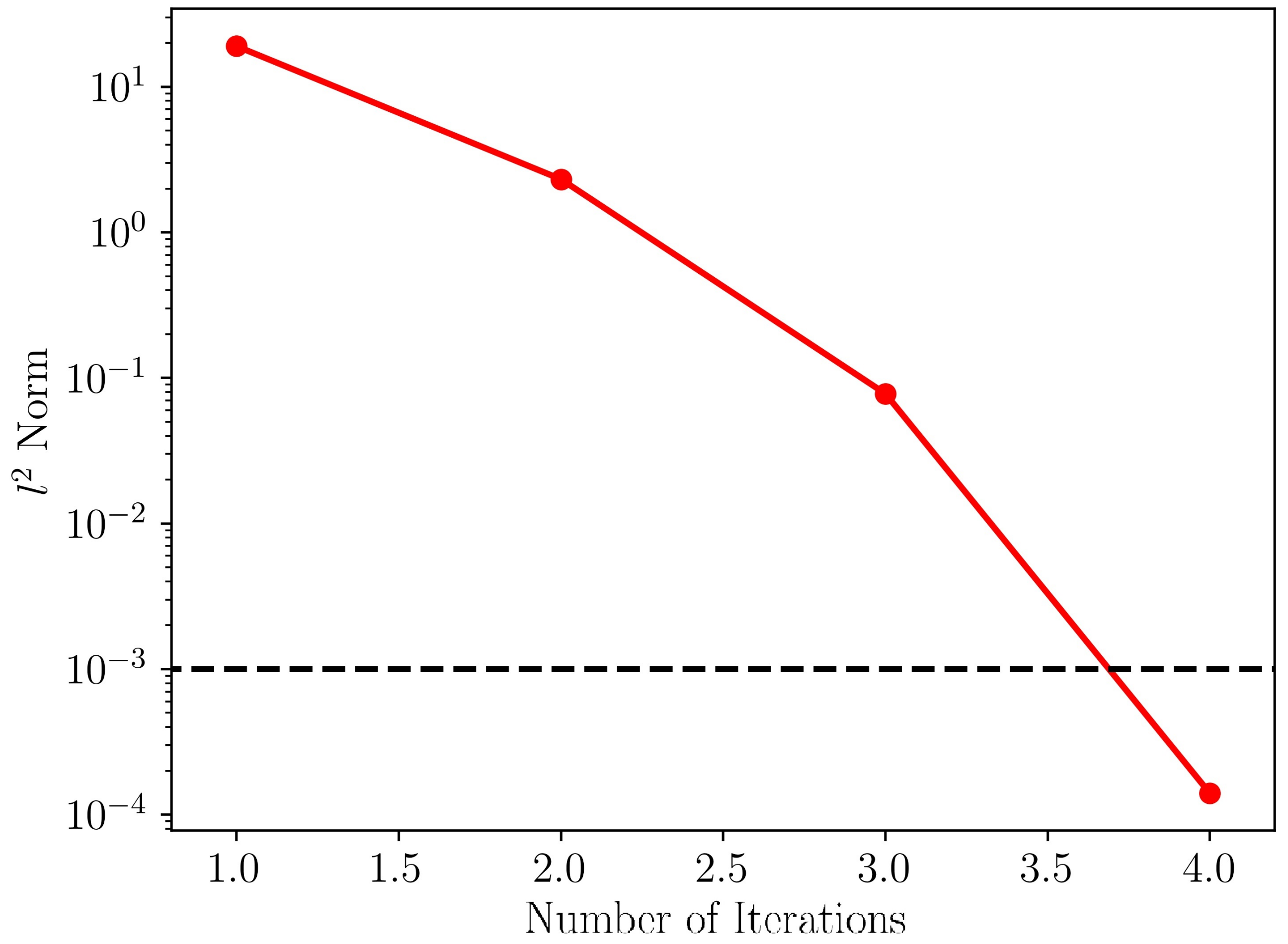
The convergence history for the NREL phase VI turbine is shown in Figure 3, and the black-dashed line shows the convergence threshold. As seen, it takes 5 steps for the multi-dimensional Newton’s iterations to converge.
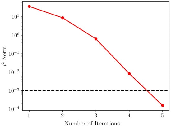
Figure 3.
Convergence history for the design of the NREL phase VI wind turbine blade using the proposed method. The black-dashed line shows the threshold for convergence.
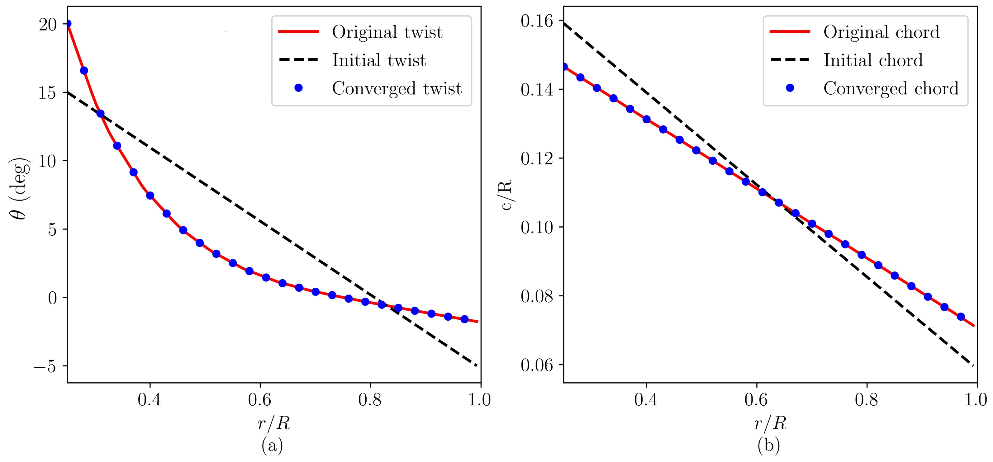
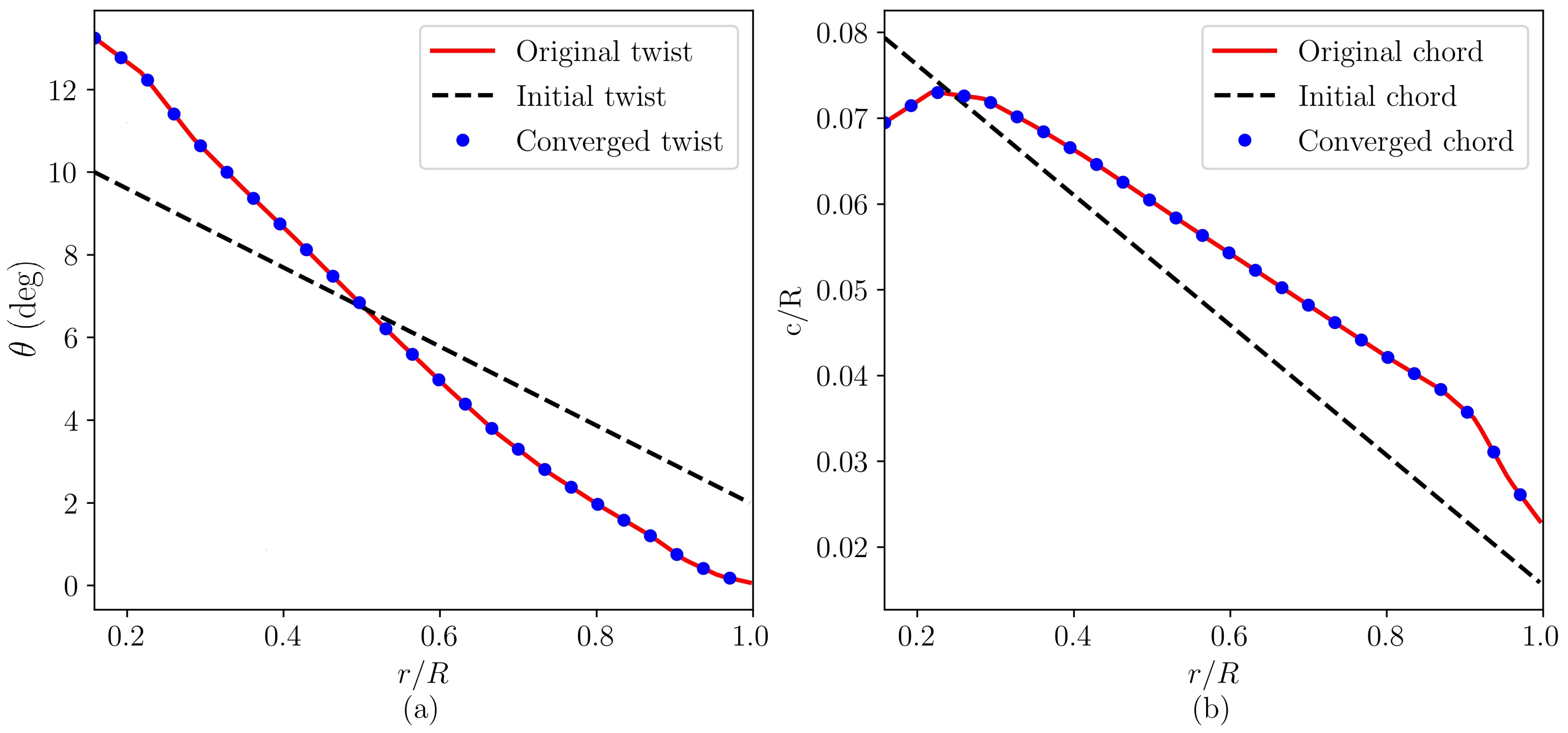
The twist () and chord (c) distributions designed by the proposed method (blue dots) are compared with the published data (red lines) for the NREL phase VI wind turbine in Figure 4. As seen, the design of the proposed method agrees well with the actual design of the blade.
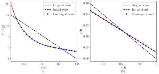
Figure 4.
Radial distribution of (a) twist and (b) chord for the S809 wind turbine blade. The red solid lines represent the original twist/chord distributions from the reference, the black-dashed lines represent the initial twist/chord distributions, while the blue dots show the converged twist and chord distributions obtained by the proposed method.
Figure 5 shows the comparison of the and from the design using the proposed method (blue dots) with the reference data (red lines), with the black-dashed lines showing the and of the initial design. As seen, the and obtained by the proposed method converge to the desired values.
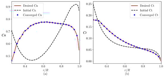
Figure 5.
Radial distribution of (a) normal and (b) tangential force coefficients for the S809 wind turbine blade.
In the following, the validation results for the NREL 5 MW wind turbine are presented. Figure 6 shows the convergence history with the residual -norm of is used. It is seen that the solutions converge after four Newton’s iterations.
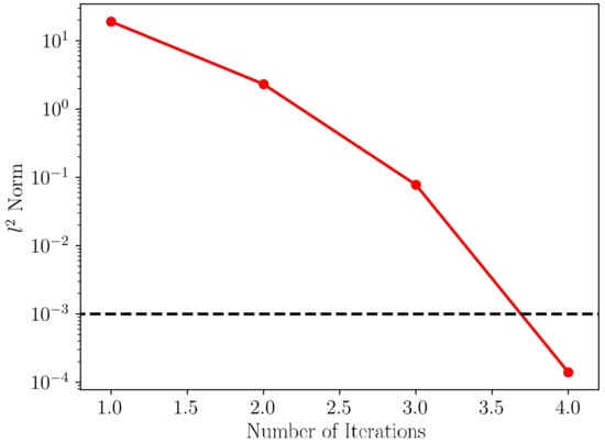
Figure 6.
Convergence history for the design of the NREL 5 MW wind turbine blade using the proposed method. The black-dashed line shows the threshold for convergence.
Figure 7 shows the twist and chord distributions of the NREL 5 MW turbine blade, in which the initial and converged distributions are shown with the black dashed lines and the blue dots, respectively, with the original distributions shown by the red solid lines. It is found that the design of the proposed method matches well with the original data of the NREL 5 MW turbine blade.
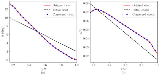
Figure 7.
Radial distributions of (a) twist and (b) chord for the NREL 5 MW wind turbine blade. The red solid lines represent the original twist/chord distributions from the reference, the black-dashed lines represent the initial twist/chord distributions, while the blue dots show the converged twist and chord distributions that are obtained by the proposed method.
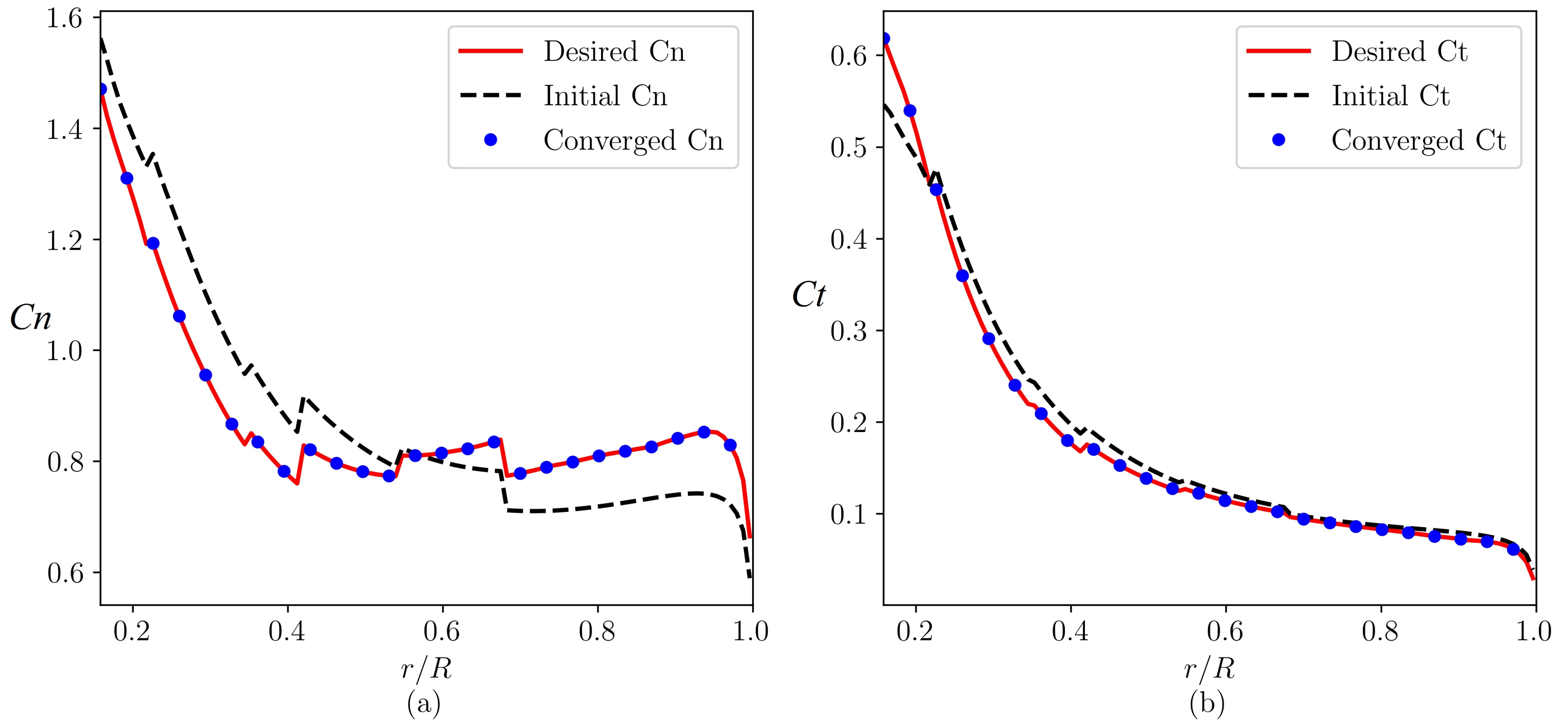
Figure 8 shows the distributions of the thrust and tangential force coefficients. As seen, an excellent agreement between the converged values and the desired values is achieved over the entire blade radial locations. It is noticed that step-like changes are observed on these curves especially for for both the design from the present work that is referenced. This is caused by the change of the airfoil type at those locations instead of any convergence issue with the proposed method.
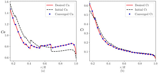
Figure 8.
Radial distributions of (a) normal and (b) tangential force coefficients for the NREL 5 MW wind turbine blade.
4. Four Variants of the NREL 5 MW Wind Turbine
In this section, the proposed method is applied to design four variants of the NREL 5 MW wind turbine [29] with different radial load distributions, including (i) the Root-CP design, (ii) the Tip-CP design, (iii) the Root-CT design, and (iv) the Tip-CT design. Note that the original NREL 5 MW wind turbine is named as the NREL-Ori turbine in the following parts. Besides, the Root-CP and Tip-CP types of wind turbines are obtained by keeping approximately the same power coefficient as that of the NREL-Ori turbine, meanwhile the Root-CT and Tip-CT wind turbines are inversely designed with the constraints of keeping approximately the same thrust coefficient as that of the NREL-Ori turbine. The “Root” and “Tip” turbines represent the designs with higher normal loads near the blade root and tip regions, respectively, when compared with the original design. The tip speed ratio is kept at 8 in this work.
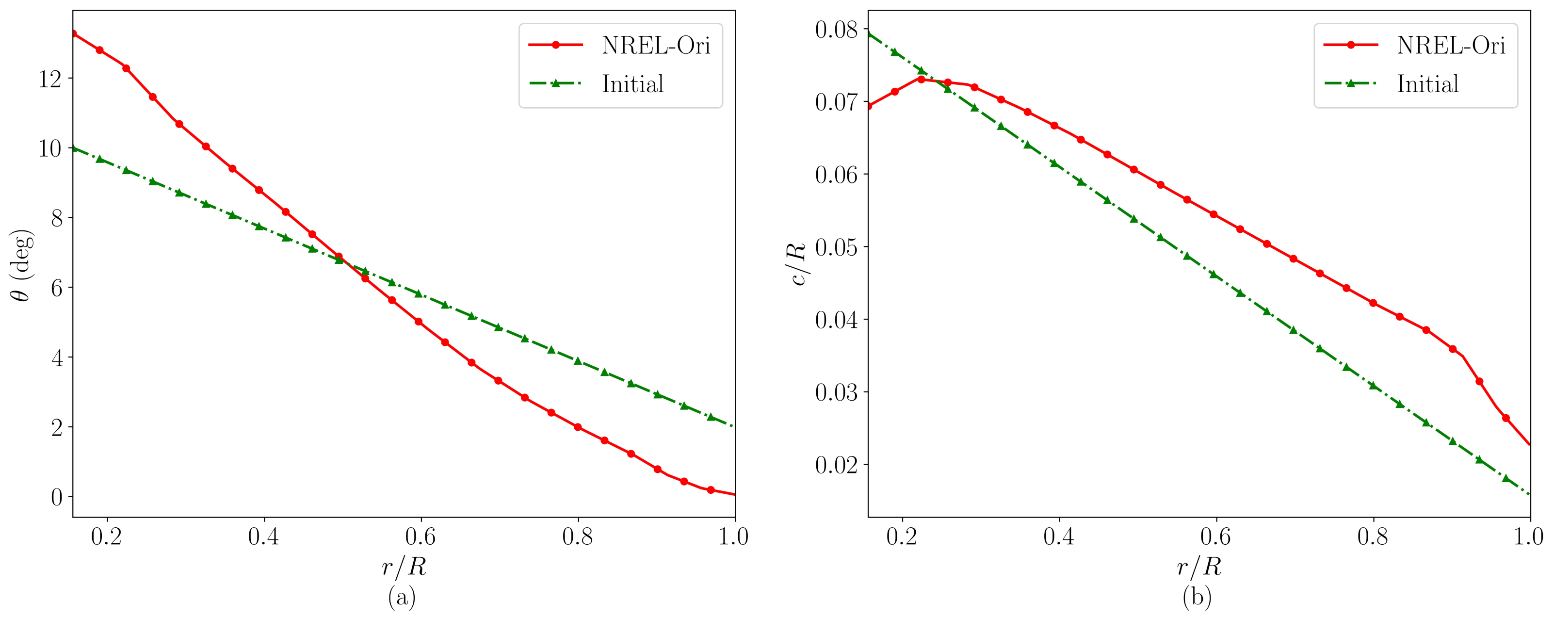
To design the variants of NREL 5 MW wind turbine, the radial distribution of the thrust coefficient () of the original design is modified. For the “Root” and “Tip” variants of design, the thrust coefficients are obtained by adding a linear function with zero mean to the original distribution. During the inverse design process, the distributions of were slightly modified by multiplying a value approximately one in an iterative way to keep approximately the same power coefficient or thrust coefficient as the original design. Figure 9 shows that the same initial twist and chord distributions are used in the inverse design of the (i) Root-CP, (ii) Tip-CP, (iii) Root-CT, and (iv) Tip-CT cases. The red lines represent the twist and chord distributions of the original NREL turbine, while the green lines represent the initial values used in the other four cases. As seen, the same initial values are used for all cases.

Figure 9.
The distributions of the initial (a) twist, and (b) chord. The red line shows the original twist and chord distributions of the NREL-Ori turbine, while the green lines show the initial values used in the inverse design.
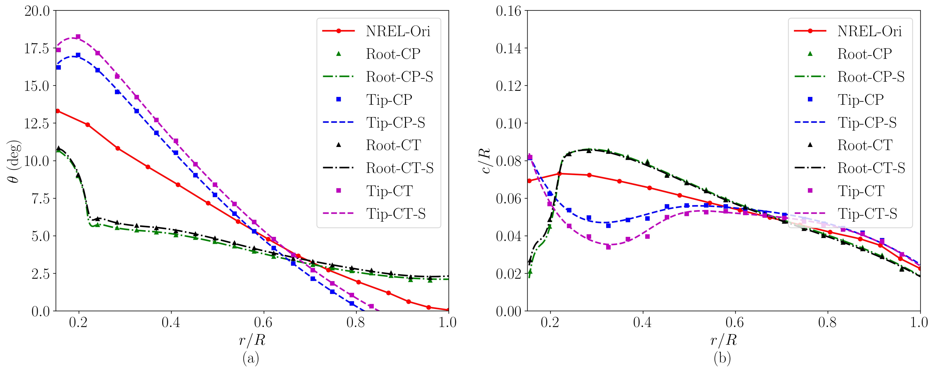
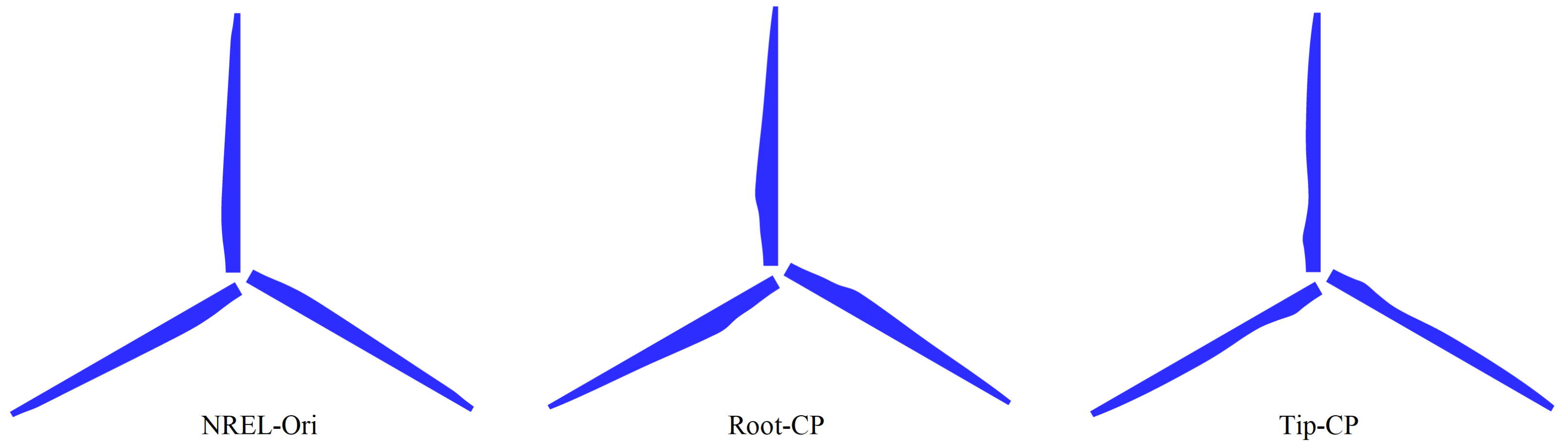
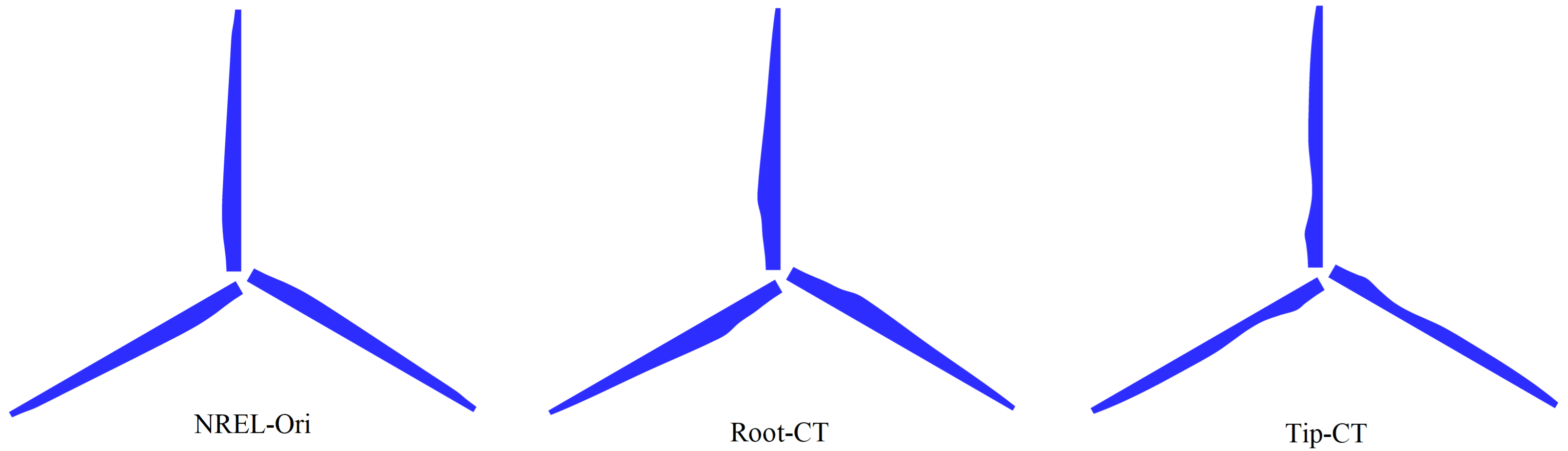
In practice, blade twist and chord distribution should be smooth enough for the manufacturing process. Therefore, in the present study, the twist and chord distributions designed by the proposed method are smoothed using the univariate spline method with the smoothing factor selected as 0.5 [36,37]. Figure 10 plots the obtained distributions of twist and chord. Meanwhile, the blade shapes from different variants of designs are shown in Figure 11 and Figure 12. In the middle part of the blade, it is seen that the chord lengths of the “Tip” type blades are narrower and wider in the near-root and near-tip regions, respectively, which are in the exact opposite way for the “Root” type blade designs, a result from the different distributions of the force coefficients for the two types of blade designs. The momentum mixing in wind turbine wakes happens at different scales. In the shear layer near the wake boundary in the radial direction, a larger gradient of the streamwise velocity in the radial direction can result in a higher mixing rate, which is the case for the “Tip”-type blades as shown in our recent work [38]. In a larger scale, the entertainment of the wake is affected by its large scale, low frequency motion in the crosswise direction, the so-called wake meandering. The literature has shown that the hub vortex plays an important role on the initiation and intensification of the wake meandering. It was shown in [38] that, compared with the “Tip” type blades, the turbulent mixing of the wake of the “Root” type blade is lower in the near wake but higher in the far wake, which is probably related to the onset of wake meandering being different for the two designs.
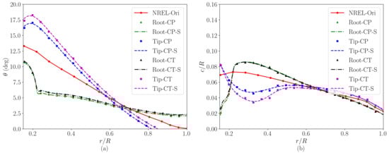
Figure 10.
Radial distributions of (a) the blade twist angle, and (b) the blade chord of the four variants of the NREL 5 MW turbine. The red lines, green lines, blue lines, black lines, and magenta lines show the twist and chord distributions of the NREL-Ori, (i) Root-CP, (ii) Tip-CP, (iii) Root-CT, and (iv) Tip-CT wind turbines, respectively. The red, green, blue, black, and magenta symbols show the non-smoothed results, while the corresponding lines represent the smoothed results.
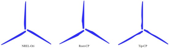
Figure 11.
Blade shapes for the variants of NREL 5 MW turbine with the same power coefficients.
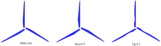
Figure 12.
Blade shapes for the variants of NREL 5 MW turbine with the same thrust coefficients.
The performance of the variants of the NREL 5 MW turbine is shown in Table 2. It is seen that when keeping the same power coefficients, the thrust coefficients of the Root-CP and Tip-CP turbines are slightly higher than the NREL-Ori turbine at −2.76% and 8.47%, respectively. While keeping the same thrust coefficients, compared with the NREL-Ori turbine, the power coefficients of the Root-CT and Tip-CT are somewhat less, at −1.33% and 4.68%, respectively.
Table 2.
Performances of different variants of the NREL 5 MW wind turbine designs.
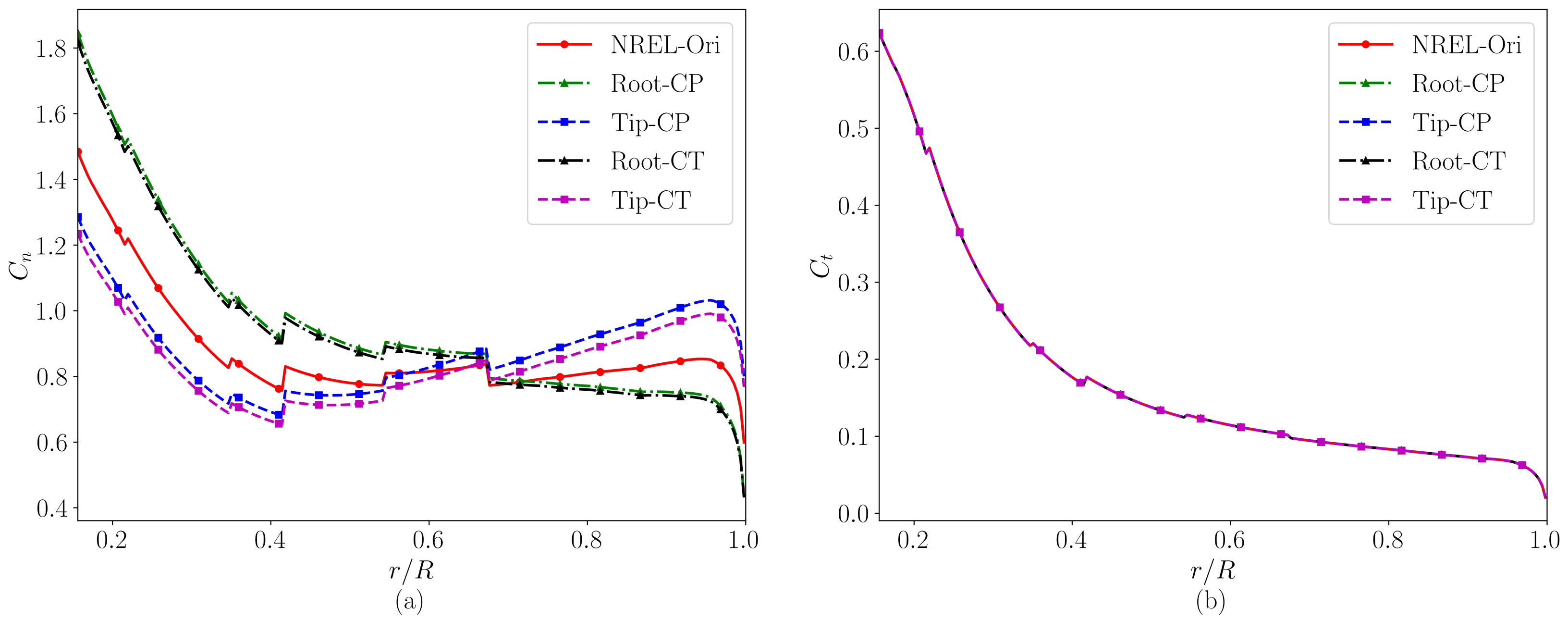
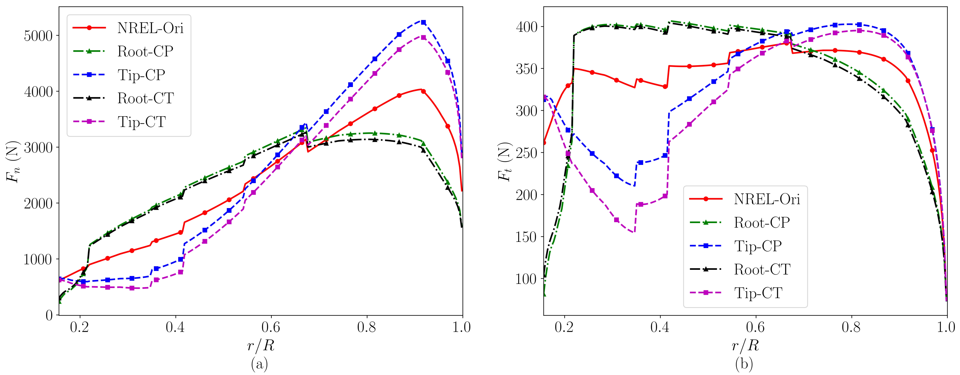
The thrust coefficient and the tangential force coefficient of the designs of the variants of the NREL 5 MW turbine are plotted in Figure 13. Meanwhile, the thrust and tangential force are plotted in Figure 14. As seen, compared with the NREL-Ori turbine, the “Root” type designs (both Root-CP and Root-CT) have higher loads near the blade root and lower loads near the blade tip, while the loads of the “Tip” designs (both Tip-CP and Tip-CT) are distributed in an opposite way. It should be emphasized that the objective of this work is to design turbine blades with different force distributions in the radial direction, which has been shown to have significant effects on the evolution of wind turbine wakes [5,38]. The blade designs obtained here together with the original design provide a basis for a systematic study on how different blade designs affect the wake characteristics.
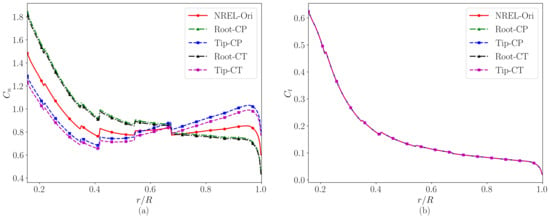
Figure 13.
Converged distributions of the (a) normal force and (b) tangential force coefficients. The red lines, green lines, blue lines, black lines, and magenta lines represent the results of the NREL-Ori, (i) Root-CP, (ii) Tip-CP, (iii) Root-CT, and (iv) Tip-CT wind turbines, respectively.
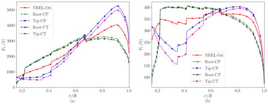
Figure 14.
Converged distributions of the (a) normal force and (b) tangential force. The red lines, green lines, blue lines, black lines, and magenta lines represent the results of the NREL-Ori, (i) Root-CP, (ii) Tip-CP, (iii) Root-CT, and (iv) Tip-CT wind turbines, respectively.
The blade bending moment plays an important role when carrying out fatigue analysis on turbine blades. In Table 3, the coefficient of the flapwise bending moment about the hub is examined for different turbine designs, which is defined as,
where is the flapwise bending moment, which can be calculated using Equation (8). As seen, when compared with the original design (NREL-Ori), the from the Root-CP and Root-CT turbine designs is reduced by 3.24% and 6.48%, respectively, which, on the other hand, is increased by and for the Tip-CP and Tip-CT designs, respectively.
Table 3.
The coefficients of the blade flapwise bending moment for different turbine designs.
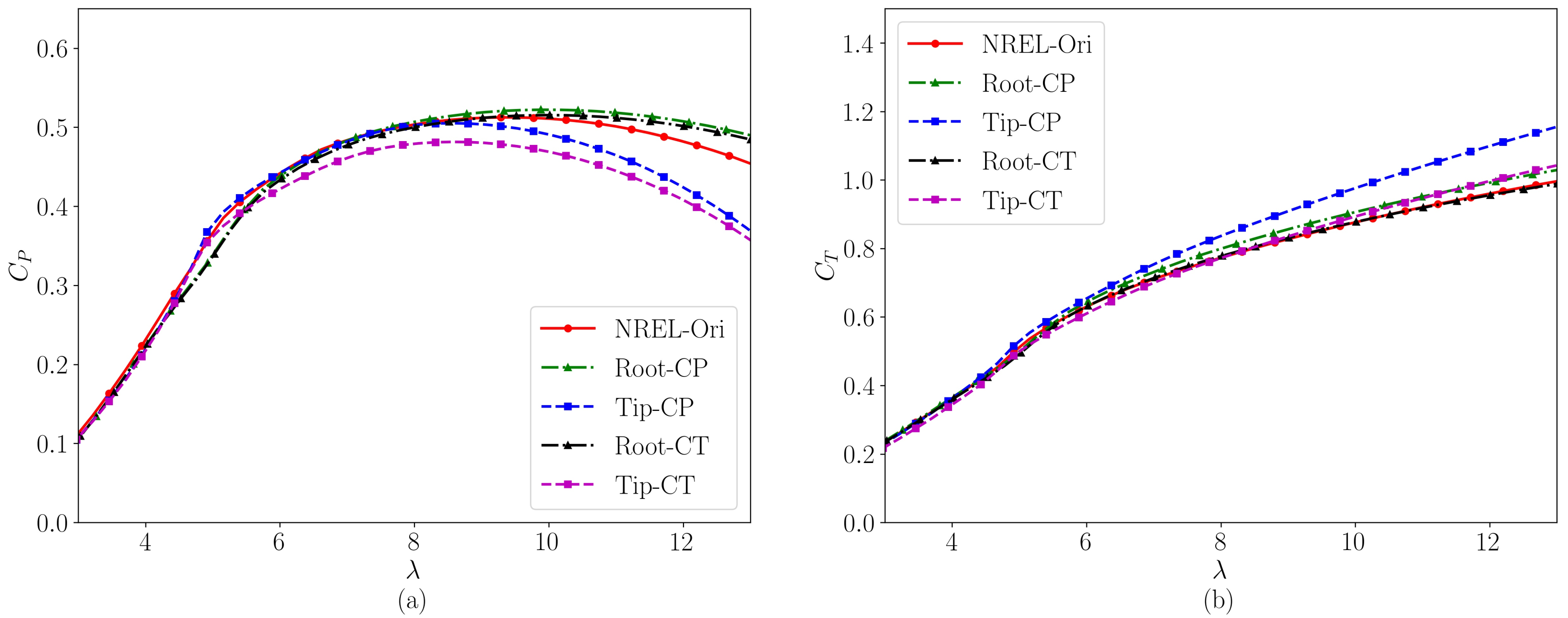
The power coefficient () and the thrust coefficient () as a function of the tip speed ratio are plotted in Figure 15 for the variants of the NREL 5 MW wind turbine. As seen, the power coefficients () of the (i) Root-CP, (ii) Tip-CP, and (iii) Root-CT designs are almost the same with that of the NREL-Ori design when is less than nine. When is greater than nine, the (i) Root-CP and (ii) Root-CT designs have a higher power coefficient than the NREL-Ori design. Considering that the “Root” type designs have lower loads near the tip and thus lower bending moments and tip-induced noise, we argue that the NREL-Root design is more robust when compared with the original design. As for their effects on wind turbine wakes, more efforts are needed in the future work.
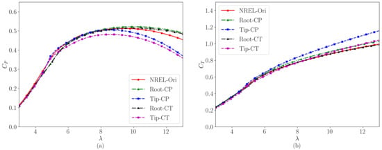
Figure 15.
Radial distributions of (a) the blade twist angle and (b) the blade chord of variants of the NREL 5 MW turbine. The red lines, green lines, blue lines, black lines, and magenta lines show the twist and chord distributions of the NREL-Ori, Root-CP, Tip-CP, Root-CT, and Tip-CT designs, respectively.
5. Conclusions
Radial distributions of blade loads affect the streamwise evolution of wind turbine wakes [5,38]. In this work, we developed an inverse method for blade designs with given distributions of normal and tangential force coefficients, and designed four variants of the NREL 5 MW wind turbine. The proposed method employs the multi-dimensional Newton’s method to design the chord and twist distributions with the normal and tangential force coefficients as the design objective, in which the blade element momentum method is employed for modeling the aerodynamics of the wind turbine. To ensure different variants of the blade designs giving the same power or thrust coefficients, the given normal force coefficients are multiplied by a coefficient, which is determined in an iterative way. The proposed method is validated using the two-bladed NREL phase VI S809 wind turbine and the three-bladed NREL 5 MW wind turbine. It is observed that the distributions of blade twist and chord designed using the proposed method agree well with the corresponding published data.
The proposed method is then applied to design four variants of the NREL 5 MW (NREL-Ori) wind turbine design, i.e., the Root-CP, Tip-CP, Root-CT, and Tip-CT designs, which have a higher load near the blade root or tip (as indicated by the left part of the name) with approximately the same power or thrust coefficients (as indicated by the right part of the name) as the original turbine design. It is observed that “Root” designs have a wider chord in the near-root region, where the chord of the “Tip” designs are relatively narrow when compared with the original NREL-Ori design. The blade flapwise bending moment about the hub is also compared for different designs, with less load observed for the “Root” (both Root-CP and Root-CT) designs. As for the power coefficients of the new designs, it is observed that the power coefficients of the Root-CP and Root-CT designs are almost the same with the original design for a TSR () less than nine. When the is larger than nine, the power coefficients of the “Root” designs are larger than the original design.
Note that the BEM method, as a low-fidelity method, cannot accurately take into account the three-dimensional effect. Although the power and force coefficients of the same blade design cannot be exactly the same with those shown in Table 2 when they are computed using a high-fidelity method, we believe that they will be close to each other and the major goal of having variants of designs with different distributions of load coefficients can still be achieved.
The present work has focused only on the load distributions without considering the structure of the blade, cost of the materials, etc. Future work shall be carried out to include more objectives in the design of the blade. To re-emphasize: The purpose of designing variants of blades is to examine how different designs affect the dynamics of wind turbine wakes. Studies on the wake dynamics of the four variants of NREL 5 MW turbine will be carried out in our future work.
Author Contributions
Conceptualization, X.Y.; methodology, G.D.; software, G.D. and J.Q.; validation, G.D. and Z.L.; writing—original draft preparation, G.D.; writing—review and editing, G.D., Z.L., J.Q. and X.Y.; visualization, G.D.; supervision, X.Y.; project administration, X.Y.; funding acquisition, X.Y. All authors have read and agreed to the published version of the manuscript.
Funding
This research was supported by NSFC Basic Science Center Program for “Multiscale Problems in Nonlinear Mechanics” (No. 11988102), National Natural Science Foundation of China (No. 12172360), Institute of Mechanics CAS, and Chinese Academy of Sciences.
Institutional Review Board Statement
Not applicable.
Informed Consent Statement
Not applicable.
Data Availability Statement
The data presented in this study are available on request from the corresponding author.
Conflicts of Interest
The authors declare no conflict of interest.
Appendix A. Implementation of the Blade-Element Momentum Method
In this appendix, the blade-element momentum (BEM) method is briefly described. The BEM method combines the one dimensional momentum theory and the blade element theory. It provides an efficient way to calculate blade loads, axial and tangential induction factor, and other characteristics of wind turbines. The BEM theory assumes that each element is independent and the force exerting on this element is a constant. As shown in Figure A1, at the rotor radial position r, the control volume that is used in the one-dimensional momentum method is an annual tube colored in green with a thickness of , the element in the rotor plane is indicated by the red dashed annual, and R is the wind turbine radius. The blue color on the rotor disk plane represents the cross section of the blade at this radial r position. The zoomed schematic of the foil is shown in Figure A2.
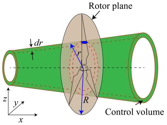
Figure A1.
Annular element control volume used in the BEM theory. The green color encompassed by the red lines shows the annular element at r with width , the gray color represents the rotor plane, and the blue ellipse represents the cross section of the blade at a radial r position.
Figure A1.
Annular element control volume used in the BEM theory. The green color encompassed by the red lines shows the annular element at r with width , the gray color represents the rotor plane, and the blue ellipse represents the cross section of the blade at a radial r position.
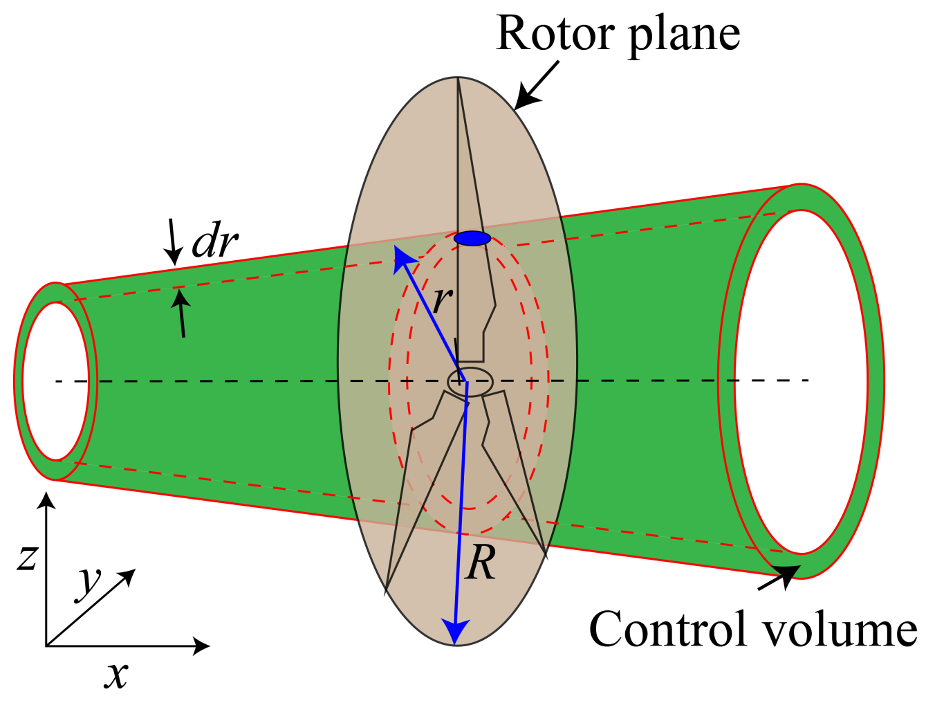

Figure A2.
Local velocity diagram at the rotor plane. is the relative incoming velocity, is the local inflow angle, is the local pitch angle, is the angle of attack, is the angular velocity of the turbine, and a and are the axial and tangential induction factors, respectively.
Figure A2.
Local velocity diagram at the rotor plane. is the relative incoming velocity, is the local inflow angle, is the local pitch angle, is the angle of attack, is the angular velocity of the turbine, and a and are the axial and tangential induction factors, respectively.
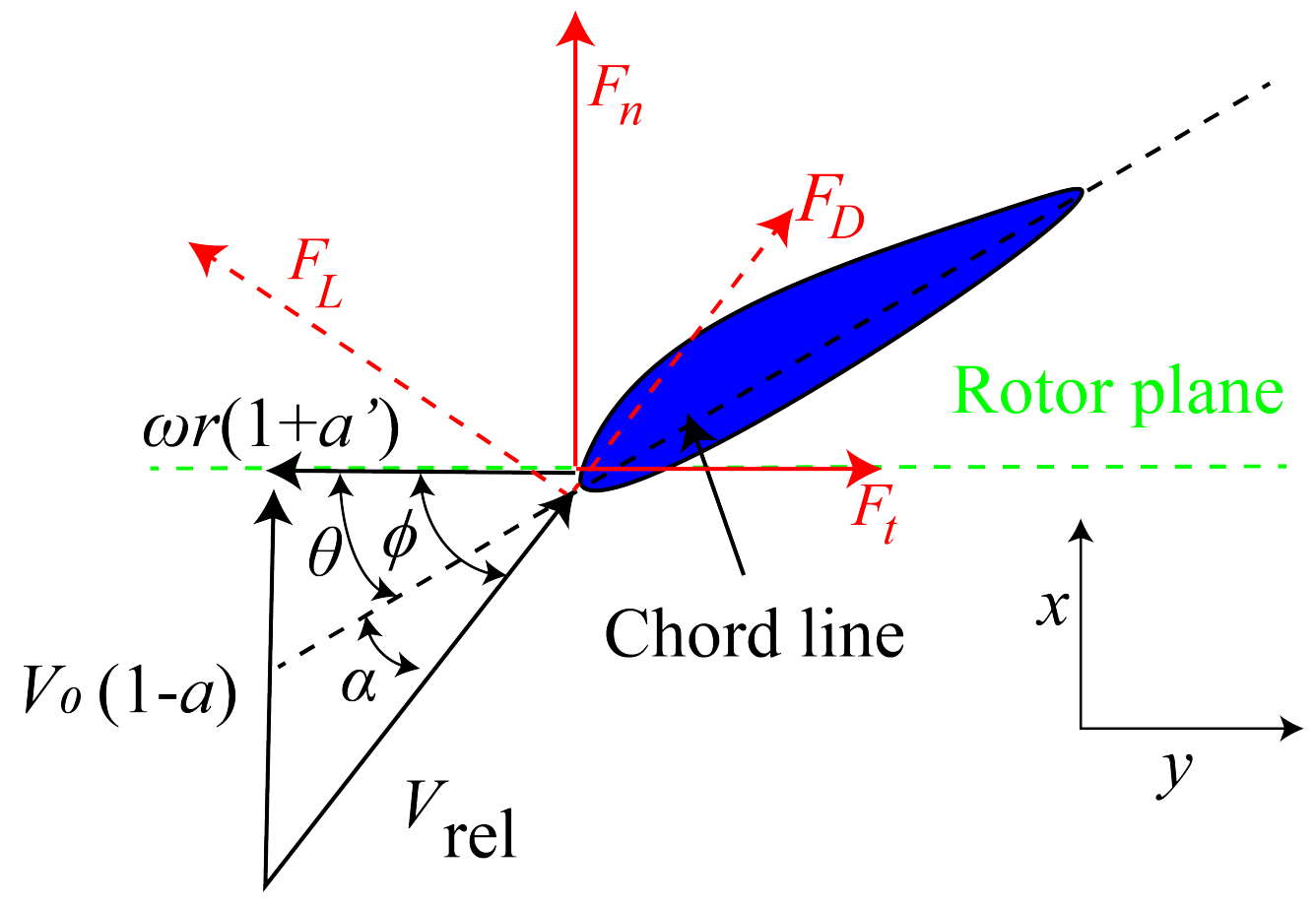
In the BEM theory, the forces exerting on the blade are computed by using lift and drag coefficients from a table for different angle of attack () as demonstrated in Figure A2.
The procedure for implementing the BEM method is given as follows:
- (1)
- Initialize the axial induction factor (a) and the tangential induction factor ():
- (2)
- Calculate the local inflow angle , which is the angle between relative incoming velocity and the rotor plane as shown in Figure A2, and computed via:where is the relative incoming velocity experienced by the turbine blades defined as a combination of the hindered inflow velocity (), and the induced velocity of the blades () due to the interaction between the blades and the surrounding fluids, in which is the angular velocity of the turbine. is the free incoming wind speed.
- (3)
- Calculate the local angle of attack (), which is the angle between the relative incoming velocity and the chord line as shown in Figure A2.where is the local pitch angle.
- (4)
- Read the lift coefficient () and the drag coefficient () from corresponding tables, which can be obtained from experiments or simulations (e.g., XFOIL [35]). The lift and drag can be calculated as follows:where c is the chord length, and is the air density. and (as shown in red dashed lines in Figure A2) are the lift and drag forces that are perpendicular to and are aligned with the direction of , respectively.
- (5)
- Calculate the local normal and tangential force coefficients ( and ) as follows:where and are the normal force and tangential force computed as follows:
- (6)
- Calculate a and by using the Glauert correction for the high axial induction factor a high and Prandtl’s tip correction [39] using the following expression,Here, is the Prandtl’s tip correction meanwhile is the solidity, which are in the following form,where R is the radial of the blade, and B denotes the number of blades. In the expressions for the induction factors, X and K are computed via:
- (7)
- If the differences in the magnitudes of a and are higher than a threshold, go to Step 2, else finish the loop and go to Step 8.
- (8)
- After obtaining the converged induction factors a and , the loads including the normal force () and the tangential force () at each radial positions are used to calculate the thrust () and torque () on the control volume of thickness as follows:At the end, integrating over the whole blades to obtain the thrust T, the power , and the corresponding thrust coefficient and the power coefficient can be obtained as:
References
- Davis, S.J.; Lewis, N.S.; Shaner, M.; Aggarwal, S.; Arent, D.; Azevedo, I.L.; Benson, S.M.; Bradley, T.; Brouwer, J.; Chiang, Y.M.; et al. Net-zero emissions energy systems. Science 2018, 360, eaas9793. [Google Scholar] [CrossRef] [PubMed] [Green Version]
- International Energy Agency Global Energy. CO2 Status Report 2018; International Energy Agency: Paris, France, 2019. [Google Scholar]
- Li, C.; Abraham, A.; Li, B.; Hong, J. Incoming flow measurements of a utility-scale wind turbine using super-large-scale particle image velocimetry. J. Wind. Eng. Ind. Aerodyn. 2020, 197, 104074. [Google Scholar] [CrossRef]
- Antonini, E.G.; Caldeira, K. Atmospheric pressure gradients and Coriolis forces provide geophysical limits to power density of large wind farms. Appl. Energy 2021, 281, 116048. [Google Scholar] [CrossRef]
- Yang, X.; Boomsma, A.; Sotiropoulos, F.; Resor, B.R.; Maniaci, D.C.; Kelley, C.L. Effects of spanwise blade load distribution on wind turbine wake evolution. In Proceedings of the 33rd Wind Energy Symposium, Kissimmee, FL, USA, 5–9 January 2015; p. 0492. [Google Scholar]
- Allen, J.; Young, E.; Bortolotti, P.; King, R.; Barter, G. Blade planform design optimization to enhance turbine wake control. Wind Energy 2022. [Google Scholar] [CrossRef]
- Tangler, J.; Kocurek, D. Wind turbine post-stall airfoil performance characteristics guidelines for blade-element momentum methods. In Proceedings of the 43rd AIAA Aerospace Sciences Meeting and Exhibit, Reno, NV, USA, 10–13 January 2005; p. 591. [Google Scholar]
- Madsen, H.A.; Bak, C.; Døssing, M.; Mikkelsen, R.; Øye, S. Validation and modification of the Blade Element Momentum theory based on comparisons with actuator disc simulations. Wind Energy 2010, 13, 373–389. [Google Scholar] [CrossRef]
- Hansen, M.O. Aerodynamics of Wind Turbines; Routledge: London, UK, 2015. [Google Scholar]
- Mahmuddin, F. Rotor blade performance analysis with blade element momentum theory. Energy Procedia 2017, 105, 1123–1129. [Google Scholar] [CrossRef]
- Chattot, J.J. Optimization of wind turbines using helicoidal vortex model. J. Sol. Energy Eng. 2003, 125, 418–424. [Google Scholar] [CrossRef]
- Hallissy, J.; Chattot, J.J. Validation of helicoidal vortex model with the NREL unsteady aerodynamic experiment. In Proceedings of the 43rd AIAA Aerospace Sciences Meeting and Exhibit, Reno, NV, USA, 10–13 January 2005; p. 1454. [Google Scholar]
- Chattot, J.J. Helicoidal vortex model for steady and unsteady flows. Comput. Fluids 2006, 35, 733–741. [Google Scholar] [CrossRef]
- Chattot, J.J. Effects of blade tip modifications on wind turbine performance using vortex model. Comput. Fluids 2009, 38, 1405–1410. [Google Scholar] [CrossRef]
- Yang, X.; Kang, S.; Sotiropoulos, F. Computational study and modeling of turbine spacing effects in infinite aligned wind farms. Phys. Fluids 2012, 24, 115107. [Google Scholar] [CrossRef]
- Yang, D.; Meneveau, C.; Shen, L. Large-eddy simulation of offshore wind farm. Phys. Fluids 2014, 26, 025101. [Google Scholar] [CrossRef]
- Yang, X.; Sotiropoulos, F.; Conzemius, R.J.; Wachtler, J.N.; Strong, M.B. Large-eddy simulation of turbulent flow past wind turbines/farms: the Virtual Wind Simulator (VWiS). Wind Energy 2015, 18, 2025–2045. [Google Scholar] [CrossRef]
- Stevens, R.J.; Meneveau, C. Flow structure and turbulence in wind farms. Annu. Rev. Fluid Mech. 2017, 49, 311–339. [Google Scholar] [CrossRef]
- Li, Z.; Yang, X. Evaluation of Actuator Disk Model Relative to Actuator Surface Model for Predicting Utility-Scale Wind Turbine Wakes. Energies 2020, 13, 3574. [Google Scholar] [CrossRef]
- Yang, X.; Pakula, M.; Sotiropoulos, F. Large-eddy simulation of a utility-scale wind farm in complex terrain. Appl. Energy 2018, 229, 767–777. [Google Scholar] [CrossRef]
- Sotiropoulos, F.; Yang, X. Immersed boundary methods for simulating fluid–structure interaction. Prog. Aerosp. Sci. 2014, 65, 1–21. [Google Scholar] [CrossRef]
- Qin, J.; Andreopoulos, Y.; Jiang, X.; Dong, G.; Chen, Z. Efficient coupling of direct forcing immersed boundary-lattice Boltzmann method and finite element method to simulate fluid-structure interactions. Int. J. Numer. Methods Fluids 2020, 92, 545–572. [Google Scholar] [CrossRef]
- Qin, J.; Kolahdouz, E.M.; Griffith, B.E. An immersed interface-lattice Boltzmann method for fluid–structure interaction. J. Comput. Phys. 2021, 428, 109807. [Google Scholar] [CrossRef]
- Selig, M.S.; Tangler, J.L. Development and application of a multipoint inverse design method for horizontal axis wind turbines. Wind Eng. 1995, 19, 91–105. [Google Scholar]
- Tang, X.; Huang, X.; Peng, R.; Liu, X. A direct approach of design optimization for small horizontal axis wind turbine blades. Procedia CIRP 2015, 36, 12–16. [Google Scholar] [CrossRef] [Green Version]
- Schubel, P.J.; Crossley, R.J. Wind turbine blade design. Energies 2012, 5, 3425–3449. [Google Scholar] [CrossRef] [Green Version]
- Méndez, J.; Greiner, D. Wind blade chord and twist angle optimization using genetic algorithms. In Proceedings of the Fifth International Conference on Engineering Computational Technology, Las Palmas de Gran Canaria, Spain, 12–15 September 2006; pp. 12–15. [Google Scholar]
- Lee, S. Inverse design of horizontal axis wind turbine blades using a vortex line method. Wind Energy 2015, 18, 253–266. [Google Scholar] [CrossRef] [Green Version]
- Jonkman, J.; Butterfield, S.; Musial, W.; Scott, G. Definition of a 5-MW Reference Wind Turbine for Offshore System Development; Technical Report; National Renewable Energy Lab. (NREL): Golden, CO, USA, 2009. [Google Scholar]
- Siddiqui, M.S.; Rasheed, A.; Tabib, M.; Kvamsdal, T. Numerical investigation of modeling frameworks and geometric approximations on NREL 5 MW wind turbine. Renew. Energy 2019, 132, 1058–1075. [Google Scholar] [CrossRef]
- Yang, X.; Sotiropoulos, F. A new class of actuator surface models for wind turbines. Wind Energy 2018, 21, 285–302. [Google Scholar] [CrossRef] [Green Version]
- Somers, D.M. Design and Experimental Results for the S809 Airfoil; Technical Report; National Renewable Energy Lab.: Golden, CO, USA, 1997. [Google Scholar]
- Giguere, P.; Selig, M.S. Design of a Tapered and Twisted Blade for the NREL Combined Experiment Rotor; Technical Report; National Renewable Energy Lab.: Golden, CO, USA, 1999. [Google Scholar]
- Hand, M.; Simms, D.; Fingersh, L.; Jager, D.; Cotrell, J.; Schreck, S.; Larwood, S. Unsteady Aerodynamics Experiment Phase VI: Wind Tunnel Test Configurations and Available Data Campaigns; Technical Report; National Renewable Energy Lab.: Golden, CO, USA, 2001. [Google Scholar]
- Drela, M. XFOIL: An analysis and design system for low Reynolds number airfoils. In Low Reynolds Number Aerodynamics; Springer: Berlin/Heidelberg, Germany, 1989; pp. 1–12. [Google Scholar]
- Chapra, S.C.; Canale, R.P. Numerical Methods for Engineers; Mcgraw-Hill: New York, NY, USA, 2011; Volume 2. [Google Scholar]
- Tahani, M.; Kavari, G.; Masdari, M.; Mirhosseini, M. Aerodynamic design of horizontal axis wind turbine with innovative local linearization of chord and twist distributions. Energy 2017, 131, 78–91. [Google Scholar] [CrossRef]
- Dong, G.; Li, Z.; Qin, J.; Yang, X. Predictive capability of actuator disk models for wakes of different wind turbine designs. Renew. Energy 2022, 188, 269–281. [Google Scholar] [CrossRef]
- Glauert, H. Airplane propellers. In Aerodynamic Theory; Springer: Berlin/Heidelberg, Germany, 1935; pp. 169–360. [Google Scholar]


Publisher’s Note: MDPI stays neutral with regard to jurisdictional claims in published maps and institutional affiliations. |
© 2022 by the authors. Licensee MDPI, Basel, Switzerland. This article is an open access article distributed under the terms and conditions of the Creative Commons Attribution (CC BY) license (https://creativecommons.org/licenses/by/4.0/).