Abstract
Residential areas are characterized by closely packed buildings which disturb wind flow resulting in low wind speeds (below 2 m/s) with a high turbulence intensity (above 20%). In order to interface between off-the-shelf wind turbines and low-quality wind, the Increased velocity (INVELOX) wind delivery system is an attractive wind augmentation option for such regions. The INVELOX setup can harness more energy than conventional bare wind turbines under the same incident wind conditions. However, these systems also have drawbacks and challenges that they face in their operation, which amplify the need to review, understand, and expose gaps and flaws in pursuit of increased power production in low wind quality environments. This paper seeks to review and simplify the advances done by various scholars towards improving the INVELOX delivery system. It provides the mathematical foundation on which these advances are rooted and gives an understanding of how the improvements better the geometric properties of INVELOX. The article concludes by proposing future research directions.
1. Introduction
With energy being a daily need, its demand can only increase given the continuous population growth coupled with the rise of urbanization. The bulk of our current non-renewable energy sources are diminishing in quantities and also bring climate change hurdles. As a result, the importance of renewable sources of energy is further highlighted as a way to mitigate climate change challenges. Among these sources, wind energy has been the most sought-after energy source for electricity production. Various forms of wind energy production are being developed, which include airborne wind systems, offshore wind energy systems, as well as the most common wind systems that are land-based. Of these wind generation systems, land-based horizontal axis wind turbine systems are mainstream, and a lot of focus has been invested towards their development [1]. One way to further improve on these systems would be to increase the propellor diameters to generate even more power. However, this is not easy as it complicates the power generation, adding on to some drawbacks that such systems already have, as mentioned in [2]. Highlights on some of these drawbacks include inefficiencies when placed in areas with low-grade winds (below 6 m/s), difficulties in transportation and handling, manufacturing logistics, transportation, icing on blades, as well as high maintenance costs, especially in tower-mounted generators [3].
Power generation by HAWT systems relies on the swept area of the rotor and drastically on the incident wind speed. The reliance on incident wind speed is such that if it is increased slightly and the swept area is reduced, more power can still be realized [4,5]. Due to this consideration, wind speed augmentation on smaller wind turbine systems has gained popularity as a way to circumvent most of the drawbacks suffered by big propeller wind turbine systems [6]. Since the investigation of the idea of ducted wind turbines, a lot of studies have been focused onto augmenting wind using of ducts. The recent studies by [7] show that wind augmentation using ducts is still an important aspect of wind energy production enhancement. Shown in Figure 1 is a novel concept within the sphere of ducted wind turbines that was named INVELOX by [8] after its ability to increase incident wind.
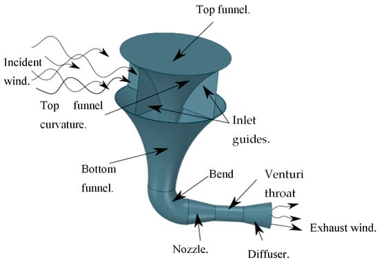
Figure 1.
An illustration of the increased velocity (INVELOX) delivery system.
One of its unique features is the omni directional air inlet. The funnel takes over this wind and compresses it into a funnel system. The nozzle–diffuser section receives the compressed wind and accelerates it through the throat section where a wind turbine is usually placed. Thereafter, the diffuser restores the pressure of the system, thus slowing the exhaust air and reintroducing it back into the atmosphere. This invention is such that when compared to traditional bare horizontal axis wind turbines, it outperformed them by a range from 18% to 235% in some applications. Added to that is its ability to incorporate more than one turbine, as done by [9], which follows that more power can be generated.
In order to then improve such a setup into applications like residential application, turbine sizing, scalability, and improve on the INVELOX setup efficiency, there is need to understand the setup better. This paper seeks to attain a under understanding of the theoretical framework, the geometric setup, and the extent to which this augmentation system has been explored by various scholars. In this venture, the gaps in knowledge and the improvements to date will be discussed holistically so as to map areas in which further improvements can be done.
2. Theoretical Framework
In open air flow, the maximum amount of air energy that can be extracted can be quantified as approximately 59.3% of the amount available in the free stream of air. This value is commonly referred to as Betz limit, which means that a bare turbine cannot extract more than 59.3% of the energy from incident air stream. However, the case is different when considering systems that have elements that are capable of modifying the flow of air without extracting part of the energy themselves. Diffuser augmented turbines, most air concentrating ducts, and, in particular, INVELOX are examples of such systems where, as a result, the Betz limit is breeched, and a higher energy extraction limit can exist. The illustration in Figure 2 shows the nozzle–diffuser section of INVELOX, which generally resembles a cylindrical delivery tube.
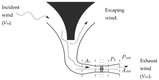
Figure 2.
The demarcated sections of the nozzle–diffuser part of INVELOX.
2.1. Power Model
A mathematical model can be developed using the Reynolds transport theorem, which states that the time rate of change of an extensive property within a system is equal to the accumulation rate of that property in a control volume and the net outflux rate of that property through the control surface of that control volume. Equation (1) below expresses the theorem.
where is the extensive property within the system, is the intensive property, is the density, and is the velocity as observed from the control volume. However, in practice, most applications such as INVELOX operate in steady-state conditions, that is, there is no accumulation within the control volume. Therefore, by substituting mass, velocity, and specific energy as the intensive property in Equation (1) and performing a control volume analysis of mass, momentum balances, and energy conservation for inviscid, axisymmetric, and incompressible flow results in the following equations.
where is the velocity vector, r is the radius; is the density of air; A represents the control surface area vector; is the unit vector in z-direction; p is the pressure; T is the thrust acting on the rotor; is the torque; and P is the power extracted from the rotor. Moving free-stream air, being a fluid, carries energy in the form of mechanical/pressure energy and also kinetic energy. This specific energy can be expressed in the form of Equation (6).
After air is collected by the omnidirectional intake of INVELOX, it is directed towards the nozzle–diffuser section where, in the throat section, work is done by the air on the turbine blades, and thus its energy is converted to mechanical energy. Before the air steam reaches the turbine blades, it undergoes a shear loss, which can be ignored for simplicity purposes. The enthalpy, therefore, in the air stream, which goes through a cross sectional area A1, can be expressed by Equation (3) as.
where represents the mass flowrate through the INVELOX system. Thus, the power in the wind passing though the INVELOX can be expressed as
Equation (4) above highlights the two main channels with which power is extracted from flowing incident wind by the INVELOX system. These are, namely, the increased kinetic energy in wind, which increases the term , and also the changes in potential energy as wind moves from the inlet to the outlet. It is due to these two characteristics that INVELOX turbines are able to harness more power beyond the traditional bare wind turbines. In a bid to further improve these gains that are only possible using such a delivery system, researchers have simulated and investigated a number of geometric structures changed and modifications. While these investigations are reviewed in the next section, the unique power augmentation of INVELOX can be expressed mathematically. By introducing a pressure coefficient such that
where is the back pressure at the exit of the diffuser, the kinetic energy loss can also be expressed as
as a result, Equation (4) takes the flowing form.
The mass flow rate can be expressed as where . Equation (5), which expresses the power that is expected to be extracted by INVELOX, thus transforms into Equation (6) below.
A bare traditional wind turbine of the same size at the same incident wind speed will extract power from the wind according to Equation (7) such that
By comparing Equations (6) and (7), it is clear that the INVELOX augments power extraction from incident wind by a factor of . The factor can be ignored, since proper sizing of the diffuser will make it too small compared to the other factors. , similar to buff body wakes, is always negative, which, according to [10], is −3. The speed ratio is always positive, with [8] suggesting a value between 1 and 2.6. Consequently, the INVELOX always produces more power than the traditional bare wind turbine by the factor , which has been established to always be greater than 1. Furthermore, the value of this factor can be maximized by optimizing the geometric structure of INVELOX.
2.2. Turbulence Models
The momentum conservation equation can also be expressed (14) as
where and are velocity components, and is the Reynold stress tensor such that
where δij is the Kronecker delta, and in accordance with turbulent flows the field variables, and p have to be expressed as the sum of mean and fluctuating parts such that
By then substituting into Equation (16), it can be written as
where is the Reynolds stress tensor.
The main aim of the Reynolds averaged turbulence modelling is to express the Reynolds tensor in quantities that are known. In order to calculate the turbulence kinetic energy and turbulent dissipation rate, different turbulence models utilize different relations. For the k-ԑ turbulence model, it is assumed that the flow is fully turbulent; hence, the effects of molecular viscosity can be neglected. As such, the standard k-ԑ turbulence model is mostly valid for fully turbulent flow. Variations of the k-ԑ turbulence model have been created to improve the application of the model to different flow situations. The RNG k-ԑ turbulence model incorporates an additional ԑ term, which improves accuracy when applied to strained flows. The Realizable k-ԑ turbulence model is different in that it contains an alternative formulation for the turbulent viscosity as well as a modified transport equation for the dissipation rate. This turbulence model is able to satisfy certain mathematical constraints on the Reynolds stresses and is consistent with the physics of turbulent flows. Both the standard k-ԑ turbulence model and the RNG k-ԑ turbulence model are not realizable.
The standard k-ω model is based on some model transport equations for the turbulence kinetic energy (k) as well as the specific dissipation rate (ω). These transport equations are also considered to be the ratio of ԑ to k. Variations of the k-ω model have been developed which adds on to its accuracy for predicting free shear flows. As such, the SST k-ω turbulence model incorporates the refinements of the BSL k-ω model and also accounts for the transport of the turbulence shear stress. These refinements make it more accurate and reliable for more flow situations, such as adverse pressure gradient flows, airfoils, and also transonic shock waves compared to the standard and the BSL k-ω turbulence models.
Within the vicinity of no-slip impermeable walls, the flow characteristics differ from all other parts of the domain. Therefore, careful selection of a turbulence model should be done in order to obtain more realistic numerical results near the wall. For a detailed treatment, low-Re versions of turbulence models should be employed, i.e., the k-ω model. In addition to the adoption of this model, a finer mesh size should also be used within these near wall regions of the domain.
3. INVELOX Wind Delivery System
Figure 3 displays several variables which, when adjusted, leads to a different set of characteristics of the INVELOX delivery system.
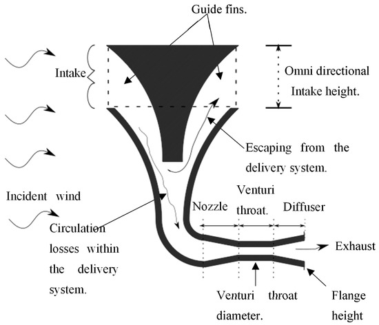
Figure 3.
A labelled INVELOX system showing the various variables affecting efficiency.
In the sections that follow, a review of the changes that have been investigated and the results thereof are discussed.
3.1. Geometric Properties of INVELOX
3.1.1. Wind Intake
The inlet area determines the inlet flow rate and, subsequently, the volume of air that can be admitted into the INVELOX system. The variations that are responsible for the changes in this area are upper funnel height and diameter. Ref. [3] performed a numerical investigation with three upper funnel heights. Their findings proved a 15% increase in venturi speed ration (SR) by increasing the inlet funnel height from 20 to 30 ft. Interestingly, Ref. [11] notes these findings and compares them with findings from [12], who investigates the effect of funnel gap. The two do not contradict, as suggested by [11], but agree that when the upper funnel gap is reduced, the air flow into the INVELOX system is also reduced due to the narrowing of the air channel, and thus increases the pressure drop, which reduces air intake [13].
A complementary study was done by [14], which validated the same result based on the speed ratio formulation and substituting the funnel height in the equation. Another extensive investigation was carried out by [13], where they compared height to diameter ration of the top funnel to the intake area. The optimum (H/D) ratio corresponded to an area of 148.7 m2, after which a further increase in area only resulted in a decrease in the height to diameter ratio. However, the maximum flow rate kept increasing with the increase in intake area. The nonlinear trends of the curves can be explained by the complicated funneling system of INVELOX [13]. The top funnel diameter also contributed significantly to the volumetric flow rate of air at the inlet system as observed by [15]. The throat velocity was increased from 14 to 16 m/s by adjusting the upper funnel diameter from 12 to 20 m, and thus, the speed ratio was improved to 2.3. It was also determined that by adjusting the diameter of the upper funnel and thus improving the intake capability of INVELOX, the speed ratio can be increased up to 3. In a study done by [16], a two-story INVELOX setup was done to investigate the effect of increasing the intake area by staking two inlet funnels in top of each other. In the study, the two-story set up ensures increased volumetric flow, as well as elevated kinetic energy, which counters the friction between the flowing wind and walls of INVELOX, as evidenced by positive pressure gradients at the bend section of the INVELOX structure. The extent of this friction is reduced by 50% in the two-story setup, which hugely eliminates flow separation on the bend section of INVELOX. An increase in average velocity corresponds to the increase in power output by 44% when compared by the single-story INVELOX setup. As a follow-up study [17], researchers modified the earlier design by adding four 45° guiding blades on the two-story inlet and doubled the inlet diameter so as to increase the volumetric flow. They tried four iterations of the design, which led them to increase the output efficiency by 20% while enhancing the omnidirectional capability of the intake system. As noted by both studies, the increased height of the INVELOX structure did not elevate maintenance cost since most of the generating equipment was still mounted closer to the ground.
3.1.2. Guide Fins
Guide fins help channel incident wind into the funnel and limit the amount hat escapes back into the atmosphere. However, an investigation was made onto how many guide fins there should be, as well as their length down the funnel for optimum operation. The most attractive length would be to extend these fins up to the bottom of the bottom funnel. The investigation done by [18] showed that the velocity at the venturi throat was increased by 5.4%, with the fins extended to the bottom of the upper funnel. In this state, the room for air to escape was minimal, which was good, but on the other hand, it created the blockage effect which increases the pressure drop within the INVELOX. As a result, less air was drawn into the system.
In a similar investigation, Ref. [5] determined the number of fins that would be the optimum for wind collection by the INVELOX wind intake. The argument is that when wind is incident at an angle that is not coaxial with the INVELOX outlet, the efficiency of the system is reduced depending on the number of fins. This is due to reverse flows that are generated on the windward side, thus limiting the air intake capability of INVELOX. A numerical study was done, and a five-blade upper funnel was found to have reduced reverse flows at angles greater than 0°. This setup was found to have the capacity of increasing the speed ration from 2 to 6%. In another study, Ref. [13] agrees with number of blades for optimum performance of INVELOX.
3.1.3. INVELOX Nozzle
The nozzle on an INVELOX system comes after a bend piping system, and it further compresses the air volume, and thus, the longer it is, the more wind speed can be generated. While keeping the throat diameter constant, further increasing on the nozzle length beyond a point will begin to counteract these positive gains. In a study performed by [19], they varied a ratio of nozzle length to throat diameter as they observed venturi speed and pressure fluctuations. In their findings, as this ration approached 1.33, lengthening the nozzle increased the windspeed ratio. However, beyond 1.33, flow separation occurred at the top of the diffuser. As a result, the flow was disrupted, thus limiting the amount of air passing through the throat section. The worst ratio they observed was 1.87.
3.1.4. Throat Diameter and Length
The sizing of the throat diameter plays an important function in achieving the optimum performance of the nozzle diffuser section of INVELOX. By reducing the diameter, more air velocity can be realized following the constricted air passage. However, mass flow is also affected since the pressure drop within the system becomes very big, thus hindering proper flow of air within the system [12]. In some cases, INVELOX has been used to house more than a single turbine. This is an advantage over bare turbine systems as it is capable of using the incident wind to a larger extend. By increasing the throat length, the wind velocity is gradually lost in favor of a uniformly distributed velocity across the entire cross section of the throat diameter. The loss of velocity for a throat elongation of between 1.5 m and 6 m was found to only be 0.09 m/s, which is quite a small sacrifice for a uniform flow under which most turbine systems perform optimally under [11,13].
3.1.5. The Diffuser Sections
A diffuser allows air to expand within the inside walls and subsequently slow down the fast-moving air. When air is slowed down, the pressure recovers to almost the levels of free-stream air. Due to this air expansion, suction of air happens towards the entrance of the diffuser as air rushes to cover for the expanding air [4,20]. The length of the diffuser enhances the deceleration effect as more air expands along the inside walls. For practical purposes, however, a longer diffuser is not advisable, since it adds on to material and construction costs. Rather, a shorter diffuser with enhanced performance is preferred [4,6,21]. The sun’s uneven heating on the earth’s surface causes the movement of air and other gasses from regions of high pressure to those of lower pressure. Due to this, areas with geographic obstructions become characterized with low wind speeds (below 2 m/s) with a high turbulence intensity (above 20%). For such places, suitable off-the-shelf wind turbines are rare since the cut in wind speed is usually higher that the average wind speeds of such religions. For such areas, a shrouding system can be employed in order to augment the wind speed to a level where small-scale wind turbines can operate. Among augmentation systems, the increased velocity (INVELOX) wind delivery system is an attractive option for unsteady, low-wind-speed regions due its pros over other conventional wind speed augmentation topologies. Such advantages include its ability to channel captured wind near the ground level, thus reducing infrastructure and maintenance costs while providing for better engineering control than other technologies. The INVELOX setup can harness more energy than conventional bare wind turbines under the same incident wind conditions. These unique characteristics amplify the need to review, understand, and optimize existing INVELOX setups in the pursuit of increased power production. This paper seeks to simplify the advances done by various scholars towards improving the INVELOX delivery system. It provides the mathematical foundation on which these advances are rooted and gives an understanding of how the improvements better the geometric properties of INVELOX. It is agreed that INVELOX has the ability to augment wind energy conversion by various magnitudes depending on the technique employed. The article concludes by proposing future research directions.
In a study to analyze the diffuser, the length ratio (ratio of the diffuser length to the throat diameter) and opening angle ratio (diffuser opening angle compared to that of the nozzle opening) were studied. After using the surface method, which is within the design express software, the optimum diffuser length was found to be 3.42 m at an opening angle of 11.33°.
The opening angle for an axisymmetric diffuser has been generally accepted as 4° so as to avoid the formation of flow separation. However, from the investigations carried out by [20] when a diffuser with a larger opening angle (grater that 15°) was compared to that with 4°, the test revealed a special trend when varying the loading coefficient (Ct) within the diffuser. For a Ct of less than 0.7, the performance characteristics of the diffuser with 15° opening angle is less than that of 4°, but this changes when it grows to beyond 0.7. It grows to exceed the performance of the 4° diffuser, reaching its maximum when the loading is 1.3. This trend is true for pressure recovery coefficient, input power coefficient, as well as acceleration factor. This places a premium on proper sizing of the turbine versus the diffuser opening angle to prevent flow separation as this hinders the expansion of the flow along the diffuser walls. It should be noted, however, that the flow separates on the inlet for all the tested diffuser loading values. Peculiar to the other, the one with loading of 1.3 has the flow reattaching soon after inlet, thus exhibiting smooth expansions of the flow and thus vastly improving the performance of the diffuser. In the study by [4], it is confirmed that the diffuser opening angle is influenced by other characteristics of the diffuser, which include its length, shape, and flange height. It has been reiterated that proper sizing of the diffuser is key in order to ensure maximum performance of the turbine placed in the nozzle–diffuser section of INVELOX.
A peculiar design was pursued by [7] where they tested a curved diffuser shroud as opposed to the straight one. The curved design accelerated incident air at its inlet better that what the straight one did. A 7% increase in air speed augmentation is overserved with the curved shroud. According to their findings, the curved diffuser still exhibited flow separation along the inside walls of the diffuser. However, the flow separation is delayed in the curved design, hence the improvement in air speed augmentation compared to the straight shroud. The curved design started to show separation 40 cm from the inlet, whereas the straight shroud exhibited flow separation at only 22 cm. This highlights the significance of the point at which the flow separates on the air acceleration through the diffuser. One of the main causes of diffuser stall is flow separation on the inside walls of the diffuser [22,23,24]. In an effort to keep the flow from separating while investigating the effects of pressure loss within the throat section to the overall performance of the duct, Ref. [25] modified the diffuser by adding slots and an internal vane. The injection of atmospheric pressure helped reduce the effects of pressure losses and helped with frictional losses on the walls of the diffuser. The multielement diffuser with a vane within performed the best by reducing the pressure loss coefficient to 0.6 while improving the extractable power to 1.8. In another study, holes were added to an INVELOX throat section with the goal of reducing pressure loss effects by [26]. The results pointed out that 35 cm holes improved mass flow rate as well as the velocity within the throat section of INVELOX. A further increase in hole size to 55 cm improved the mass flow rate, but it neutralized the effect of the nozzle-diffuser section of INVELOX. Using an airfoil shaped annular shroud as an improvement, Refs. [27,28] investigated the geometric parameters of the best setup of the multi-element diffuser. Using an airfoil shaped diffuser structure improves the laminar flow qualities as well as reduces the drag forces on the duct [28]. After using the one factor at a time (OFAT) and design of experiments (DOE) approaches, their findings demonstrated that an acceleration ratio of 1.78 and a drag coefficient of 1.84 can be achieved by carefully sizing the shroud, flap, and radial distance.
In order to further enhance the performance of the diffuser, most researchers have adopted the addition of a brim or a flange, which is a vertical ring at the diffuser outlet. Such a geometric setup leads to the formation of some vortices behind this flange. These vortices reduce the back pressure behind the flanges, thus improving the mass flow rate through the diffuser. The authors of [29] found that, in addition to the main factors affecting the performance of a diffuser, the flange height is among the important variables that make up the optimum diffuser. They also established that the contribution of the flange alone in accelerating the wind is in the range from about 21% to 22%.
In a study by [30] where they employed wind tunnels experiments and particle image velocimetry (PIV) to determine the impact of flange height on the enhancement of performance on the diffuser, they found that increasing the height of the flange resulted in an increase in wind acceleration within the diffuser section. However, there exist an optimal ratio (flange height/diffuser inlet section diameter (Hopt/Da)), which was found to further increase the height; this did not have any significant effect on the incident air acceleration. Behind the flange on the diffuser, two counterclockwise vortices form and move away from each other as well as the flange with the increase in flange height.
These vortices produce low-pressure regions at their center and are responsible for the acceleration of air at the inlet of the diffuser. Beyond the optimum flange height ratio, these two vortices become so far away from each other and the diffuser to contribute to any further acceleration of wind; thus, the pressure coefficient at their centers starts to decrease with increase in height. Therefore, the pressure coefficient at the vortices’ center and their location determines strongly the ultimate performance of the diffuser for a flanged diffuser [30,31]. A control system which controls the flange height and thus controls the vortices that form would be instrumental in keeping the diffuser operating at an optimum level.
In a study by [4], flange height is expressed as a fraction of the diffuser diameter and highlights that at a 0.4 diameter is when further increase in flange height no longer corresponds to an increase in incident air acceleration. In the study, they also noted that the optimum flange height has a relationship with the diffuser length. For a shorter diffuser length ratio (diffuser length/inlet diameter = 1.5 or 2), a flange height ratio of (flange height/inlet diameter) = 0.3 is considered optimum. For an intermediate diffuser length (diffuser length/inlet diameter = 3), a flange height ratio of (flange height/inlet diameter) = 0.4. is considered optimum, and then for a long diffuser length (diffuser length/inlet diameter = 4), a flange height ratio of (flange height/inlet diameter) = 0.2 is considered optimum [4,21].
In a similar study to that mentioned above, Ref. [32] used PIV to study the performance of a flanged diffuser. In their study, the flange alone contributed between 13% and 23%. In the study, a short diffuser of diffuser length/inlet diameter = 1.78 was used as they tested various flange heights. A plot against the dimensionless wind velocity and the diffuser length/inlet diameter ratio was used to show their findings. An interesting trend was presented in the graph, which showed a critical flange height to inlet diameter of 0.1. Values below were deemed as zone 1, which displayed a linear increase in the velocity with flange height. A slope of 1.245 was observed. However, beyond the critical value, the slope drops from 1.245 to 0.206; the increase in height seemed to have no effect on the wind acceleration in at the diffuser entrance. At this point, they found that it would require the critical height to be increased five-fold in order to produce a 5% increase in wind speed in the diffuser. However, the mechanical cost of the wind on the diffuser would outweigh the benefits.
A huge pressure drop within the venturi throat section leads to the formation of vortices due to flow separation within the diffuser. These disrupt linear flow and thus limit air inlet into the INVELOX system. In another study, Ref. [26] sought to control the pressure drop by drilling some holes on the venturi section of INVELOX to ease out the pressure gradient. Several sizes of holes were experimented in pursuit of the optimum size hole. Of the three hole sizes experimented with, the 35 cm holes provided a balance between reduce the huge pressure drop and still maintaining the converge–diverge geometry on the air stream.
On the issue of flange height variation, in the study by [19], several flange height/throat diameter ratios are simulated to observe INVELOX reaction different values of flange height. Their output agrees well with other scholars in that all the values of flange height ratio below the value of 1.5 resulted in a linear increase relationship with throat wind speed. Further increase in flange height results in a subtle change in throat wind speed and, subsequently, a decrease in throat velocity. The values evaluated in the study are 0.083, 0.125, 0.133, 0.15, 0.166, 0.208, 0.25, and 0.33.
One of the pioneer researchers who investigated on the flange angle as a variable for windspeed augmentation within a diffuser was [33]. As previously outlined, the addition of a flange amplifies the acceleration of a diffuser setup. The flange angle can also be used to further this application. In the study, they investigated how varying the flange angle for a range of angles from −25° to 25° would affect the overall wind velocity at the entrance of the diffuser. The very same diffuser dimensions were used for all the increments of 10° that was tested on the design. Their results highlighted that the optimum angle for maximum acceleration of incident wind was 15° where the incident air was accelerated from 4.5 m/s to 5.63 m/s. They also noted that negative flange angles did not contribute much to wind speed augmentation.
The study by [19] goes on to investigate the influence of flange angle relative to the INVELOX diffuser axis. The flange angles investigated in the study are 2.5, 5, 7.5, 10, and 15 degrees. Varying the flange angle can also increase the suction capacity of the diffuser section and thus increasing throat velocity. When a positive angle is applied to the flange, the strength on the vortex created is strengthened. However, this trend can only be seen for positive angles less than 30°, beyond which the vortex is eliminated and thus has a counter effect on the diffuser. In their results, the flange with the angle of 5° had the best performance. Using this angle, the observed a 21% increase in the throat velocity ratio. A different result, however, is observed by [4] in their study of the effect of flange angle. In the study, they investigated the angles −15°, −30°, 0°, 15°, and 30°. Their results reveal that 15° angle produced the best results, which improved the velocity ratio to 1.77. however, the negative angles did not improve the performance of the diffuser but rather interfered with the vortex and thus eliminated it.
A unique study was done by [7] where they investigated the effect of flange angle on a curved diffuser. The flanges ranged from −35° to 35° in their study; they also observed stout vortex formation at the back of the flange. In their findings, they agree that as the angle becomes larger, it reduces the strength of the vortices formed. Their results reveal that 10° is the optimum angle to improve the inlet velocity from 5 to 8.68 m/s. As a result of this improvement in the suction capacity of the diffuser, a 15% turbine power generating capability is realized. By varying the flange angle, the points at which flow separation initiates is changed as compared to a normal flange (0° inclination). This finding agrees with several observations that by changing the point at which flow separation within the diffuser, its performance can be improved or diminished.
4. Operational Challenges of INVELOX
4.1. Wind Direction
Various scholars have come to the conclusion that the claims by the inventor of INVELOX have limitations in terms of the performance of INVELOX when approached by wind from different directions. When the wind is greater than 120°, the efficiency of the system falls, with 135° and 235° being the ones with the lowest speed ratios. This is due to the velocity component in incident wind, which opposes the flow direction in the venturi section. This increases the pressure in the venturi section, thus reducing the overall speed ration of the system [34]. In a numerical study, Ref. [35] considered the practical boundary later influence to the acceleration of wind in an INVELOX system. The study confirmed the previous results and added that when the atmospheric boundary layer is considered, the reduction in efficiency is enhanced. In another study, Ref. [34] suggested that the elbow section be straightened to reduce the effect of incident wind on the outlet of the system. Furthermore, they added a shield at the diffuser, thus improving the suction capacity of the diffuser. The performance of the INVELOX system was increased in terms of its omnidirectional intake characteristics, and the speed ratio also increased by 42%.
4.2. Escaping Air
The duty of the omnidirectional air intake is to receive incident air from all directions and subsequently channel it towards the venturi throat. However, practically not all collected air ends up in the throat section, as a considerable amount of it escapes into the atmosphere as observed by [18]. As incident air reaches the intake area, it is channeled by the upper funnel into the delivery system; however, this creates a lower pressure on the leeward side of the upper funnel, thus causing a significant portion of air to escape. This is undesirable, as depicted graphically by [36] who solved this numerically by employing a roof structure on the INVELOX air intake hopper (ACRIS system). The roof was controlled by a servo motor, which helped improve the INVELOX structure against strong wind, avoid singularity at speeds of 15–20 m/s, avoid turbine overspending, and most importantly, reduce escaping air on the intake hopper. Compared to the basic INVELOX design, the improved model improved the venturi velocity by 18%. Similarly, a morphing system was introduced by [37] which improved on the ACRIS system. It provides a more adaptable roof design and also has the ability to perform in a wider range of wind speeds. An adaptive Fuzzy-PI controller, which utilizes tracking anti-windup, beefs up the controllability of the roof, and most importantly, reduces escaping air. When compared, the moph system improved the ACRIS by 6% in relatively low wind speed (5 m/s) and could accelerate 10 m/s wind to around 25 m/s which the basic INVELOX system cannot do. Ref. [18] also proposed three modifications to the basic INVELOX delivery system. Basically, the curtain system proposed would seal off unparticipating parts of the intake system and only leave a quarter facing the incident wind. The guide flaps were elongated to limit the pathway used by the escaping air. They also performed a numerical investigation from which it was established that as much as the elongated flaps reduced escaping air, they also increased the pressure drop due to the narrowed air path, thus reducing the mass flow rate into the system. The resultant curtain design with no elongated guiding flaps improved the speed ration by 25% with non-uniform venturi velocity in extended guide flaps modifications.
5. INVELOX Optimization
5.1. Nozzle–Diffuser Optimization
The INVELOX wind delivery system plays a vital role in its function of enabling the capture of energy is low wind speeds. Further improvement of its augmentation characteristics would enhance its application, especially with the adoption of electric vehicles, which may need charging ports in various places. The aspect of simultaneously optimizing geometric parameters with the goal of increasing the augmentation ratio have been done on the nozzle–diffuser section by various scholars. A parametric optimization approach was employed by [19] involving the use of historical data optimization in order to replace the conical nozzle with an ideal nozzle to suit their expectations. The diffuser section was optimized using the response surface method considering the diffuser angle and length as design variables. The resultant nozzle–diffuser section was further modified by the addition of a flange along with a flange angle of 0.15. An improvement of 21% in speed ration was observed after the optimization of the nozzle–diffuser section of INVELOX. In a similar case, Ref. [38] used three design variables as input to the response surface method with the aim of optimizing the nozzle–diffuser duct for wind speed augmentation. After simulations, an augmented wind speed of 21 m/s was obtained for a throat diameter, contraction ration, and length of 0.16, 2, and 0.16, respectively. Consequently, another study involving more design variables to optimize the nozzle-diffuser duct was done by [39]. The diffuser length and angle, concentrator angle and length, flange height, and throat length were used as design variables, yielding an optimal augmentation ratio of 1.953. This value was obtained at a concentrator angle of 20°, diffuser angle of 10°, throat length of 70 mm, concentrator length of 375 mm, diffuser length of 975 mm, and flange height of 100 mm. The use of a combination of response surface method and CFD proved to be a great multiparameter optimization tool for wind delivery ducts, an area which has not been looked into by many scholars [38].
5.2. Entire INVELOX Optimization
In another investigation by [40], the inventors’ INVELOX was modified using various refinements in the literature, which improved the system by 16%. In the same study, some more modifications were done to produce the modified version of INVELOX. Concepts were borrowed from the windcatcher concept, which included a novel intake, which was divided into a primary and secondary intake and a standardized venturi system. This result tackled the short-circuiting nature of the omni directional intake while, at the same time, reducing the high frictional points. The resultant INVELOX system exhibited a logarithmic relationship with increased incident wind speed different from the basic setup, which dropped the speed ratio with increased incident wind. The modified INVELOX managed to improve the speed ration to 2.77, while the wind velocity was augmented to 18.6 m/s from 6.7 m/s.
The study conducted by [41] highlights most of the geometric parameters of the INVELOX system that is reviewed in this work. The study seeks to improve the INVELOX system and goes on to develop and test a unique intake system. The top funnel diameter, its radius of curvature, the funnel depth, as well as radius of curvature of the venturi, were varied in order to improve the throat velocity. Their findings agree with the literature reviewed in this study, though they used a different approach to dimensionalize geometric parameters. For instance, they used a non-dimensional upper funnel diameter, upper funnel curvature radius, and venturi curvature radius. They divided the upper funnel diameter, the curvature diameter, as well as venturi curvature by the throat diameter. This was to facilitate scaling, to isolate the effect of other geometric, as well as to generalize the values. The resultant throat velocity improved to 10.79 m/s when the non-dimensional upper funnel diameter was set at 5.30. It rose further to 14.77 m/s when the venturi curvature radius of the venturi was set to a non-dimensional value of 6131. They agreed with the study by [18] and avoided the use of elongated guide flaps. In agreement with [12], the study observed that the throat velocity was high when the bottom of the upper funnel was 35% deep in the bottom funnel. Though [12] investigates using different incident wind speeds and depth of upper funnel into bottom funnel, the general trend is well in agreement. The novelty of the study by [40] is in the modified intake system which minimizes the mass flow chocking at the base on the upper funnel, resulting in a 320% improvement in power generation when the dome structure was added onto to the baseline INVELOX.
A different approach was employed by [11], which has been used to optimize the geometric properties of INVELOX, resulting in an improved version. After the use of surrogate-based optimization methods, optimum values for the geometric parameters were maximized and thus optimized. The venturi throat length, venturi diameter, diffuser length, diffuser angle, and the nozzle length were the parameters chosen for investigation in the first phase of the study. The second phase investigated the intake and the bottom diameter of the upper funnel, as well as the height of the upper funnel as variables. However, the intake height was maintained during the study. The venturi length was increased to 0.5 m, thus resulting in a uniform flow which favors power generation using the HAWT that is used in the study. The diffuser length was increased by 96.7% while the diffuse angle was reduced by 46.1%. These changes reduced flow separation within the diffuser, thus improving the performance of the improved INVELOX. The nozzle length was reduced by 15%, which minimized vortices in the diffuser and increased pressure drop in the diffuser. More flow is witnessed as a result in the improved INVELOX. To reduce the infamous escaping air from the omnidirectional intake of INVELOX, the upper funnel height was reduced, while its bottom increased by 18.6% and 28.8%, respectively. As a result, only 67% of entering air escaped, which is an improvement from the 75% on the base model of INVELOX. The improved INVELOX yielded a 4.2% increase in speed ratio. In their investigations, Refs. [42,43] developed four designs which they tested. The fourth one was similar to an INVELOX setup, only that it was a straight one with a slotted diffuser section. After their numerical experiments, they managed to demonstrate a gained wind speed of 53 m/s from an inlet speed of 5.5 m/s and an exit speed of 13 m/s. Table 1 below gives a summary of the methods employed for the numerical analysis of the INVELOX wind delivery system.

Table 1.
Summary of the methods used for the numerical analysis of INVELOX wind delivery system.
6. Conclusions and Discussion
Residential areas stand to benefit from the interface provided by wind delivery systems, particularly stand-alone areas in remote places where transmission lines and electrical handling equipment is not easily accessible. Off-the-shelf wind turbines coupled with these delivery systems can facilitate distributed generation and increase the utilization of the wind resource in such areas [46,47]. However, created by a wind delivery system can enable the residential installation of such turbines applicable in South Africa, especially at a time when electricity supple is not stable.
The geometric structure of INVELOX wind delivery system possesses a lot of potential in the form of optimization for better wind to electrical energy conversion. It has been established that ducted wind turbine installations in the form of INVELOX outperform bare wind turbines installations in some applications. Their ability to concentrate air drawn from a wide space, handle it, and then channel it to a turbine drastically improves the turbine output. Given their wind-handling capacity, they can be employed in areas of low wind speed (greater than 1 m/s) and turbulence intensity (less than 20%). This study reviews work done by researchers and scholars on the different geometric parts of the INVELOX, highlighting the resultant improvements affected. In Figure 4, a bar chart with references along with the resultant speed ratio. The highest speed ratios thereof are the investigations done by [17,40] where they modified the inlet design.
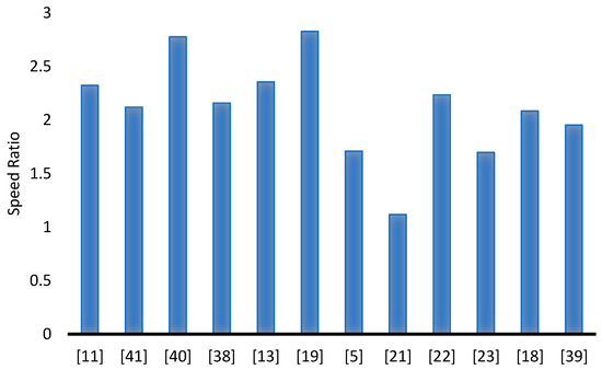
Figure 4.
A labelled comparison of various contributions by researchers of INVELOX in terms of speed ratio.
Figure 4 goes on to demonstrate how the modification of each unique part of INVELOX can bring about an improvement in throat velocity. A combination, therefore, of several modifications done by different scholars could bring about a unique wind delivery duct which will exceed the current speed ratio achievements. In most of the studies reviewed, the examination of parameters of INVELOX was conducted independently whilst using discrete values. This does not produce exact optimal values for the application of the entire INVELOX system, as only part of the system is optimized. The use of more multi-interactive parameter optimization techniques on the entire INELOX system has the potential to foster a different dimension of how the INVELOX delivery systems can be applied. By compounding the results of several parametric modifications, the overall performance can be vastly improved.
Practical construction of INVELOX systems has been limited in studies, leaving their analysis to be mostly numerical more that empirical. This limits the extent to which quantitative assessments can be made on manufacturing cost, complexity, and trade-offs when constructing INVELOX systems. However, in the few cases reviewed, challenges with size and scalability have been an issue. In the case of [37], the experiment had to be limited to only testing of the control system. For the application of INVELOX on rooftops scalability, studies have to be conducted, which will reduce the cost of manufacture and improve on sizing, which will align with local wind patterns. The complexity of manufacturing INVELOX has been seen to reduce the efficiency of INVELOX in one of the experimental cases reviewed, highlighting the need to search for better methods of manufacturing which are also cost-effective.
Author Contributions
A.G.C. contributed towards the conceptualization, writing—original draft preparation, and formal analysis of the manuscript. Writing—review and editing, as well as the funding acquisition and supervision, were performed by P.M. The project administration and provision of resources was performed by N.S. All authors have read and agreed to the published version of the manuscript.
Funding
This research received no external funding.
Institutional Review Board Statement
Not applicable.
Informed Consent Statement
Not applicable.
Data Availability Statement
No new data were created or analyzed in this study. Data sharing is not applicable to this article.
Acknowledgments
Special appreciation to the Renewable Energy-wind (RNA) of the department of research and innovation at the University of Fort Hare for their support.
Conflicts of Interest
The authors declare no conflicts of interest.
References
- Shonhiwa, C.; Makaka, G. Concentrator Augmented Wind Turbines: A Review. Renew. Sustain. Energy Rev. 2016, 59, 1415–1418. [Google Scholar] [CrossRef]
- Konstantinidis, E.I.; Botsaris, P.N. Wind Turbines: Current Status, Obstacles, Trends and Technologies. IOP Conf. Ser. Mater. Sci. Eng. 2016, 161, 012079. [Google Scholar] [CrossRef]
- Anbarsooz, M.; Hesam, M.S.; Moetakef-Imani, B. Numerical Study on the Geometrical Parameters Affecting the Aerodynamic Performance of INVELOX. IET Renew. Power Gener. 2017, 11, 791–798. [Google Scholar] [CrossRef]
- Ahmed, M. Elsayed Design Optimization of Diffuser Augmented Wind Turbine. CFD Lett. 2021, 13, 45–59. [Google Scholar] [CrossRef]
- Farokhzade, A.; Maghrebi, M.J. Inlet Parameters Effects of INVELOX on the Aerodynamic Performance Using Numerical Simulation. J. Appl. Fluid Mech. 2021, 14, 1511–1520. [Google Scholar] [CrossRef]
- Watanabe, K.; Ohya, Y. A Simple Theory and Performance Prediction for a Shrouded Wind Turbine with a Brimmed Diffuser. Energies 2021, 14, 3661. [Google Scholar] [CrossRef]
- Heyru, B.; Bogale, W. Flow Field Analysis and Testing of Curved Shroud Wind Turbine with Different Flange Angle. Cogent Eng. 2022, 9, 2095951. [Google Scholar] [CrossRef]
- Allaei, D.; Andreopoulos, Y. INVELOX: Description of a New Concept in Wind Power and Its Performance Evaluation. Energy 2014, 69, 336–344. [Google Scholar] [CrossRef]
- Allaei, D.; Tarnowski, D.; Andreopoulos, Y. INVELOX with Multiple Wind Turbine Generator Systems. Energy 2015, 93, 1030–1040. [Google Scholar] [CrossRef]
- Bussel, D.G.J.W.V. The Science of Making More Torque from Wind: Diffuser Experiments and Theory Revisited. J. Phys. Conf. Ser. 2007, 75, 012010. [Google Scholar] [CrossRef]
- Ding, L.; Guo, T. Numerical Study on the Power Efficiency and Flow Characteristics of a New Type of Wind Energy Collection Device. Appl. Sci. 2020, 10, 7438. [Google Scholar] [CrossRef]
- Ding, L. Study of INVELOX Wind Turbine Considering Atmospheric Boundary Layer: Based on Numerical Simulation. J. Phys. Conf. Ser. 2020, 1600, 012063. [Google Scholar] [CrossRef]
- Ghorani, M.M.; Karimi, B.; Mirghavami, S.M.; Saboohi, Z. A Numerical Study on the Feasibility of Electricity Production Using an Optimized Wind Delivery System (Invelox) Integrated with a Horizontal Axis Wind Turbine (HAWT). Energy 2023, 268, 126643. [Google Scholar] [CrossRef]
- Wibowo, T.T.; Daulay, F.H.; Suryopratomo, K.; Budiarto, R. Numerical Study of the Effect of Geometry Variation on the Performance of Innovative Design Wind Speed Enhancer. E3S Web Conf. 2018, 42, 01013. [Google Scholar] [CrossRef]
- Akour, S.N.; Bataineh, H.O. Design Considerations of Wind Funnel Concentrator for Low Wind Speed Regions. AIMS Energy 2019, 7, 728–742. [Google Scholar] [CrossRef]
- Billah, S.M.B.; Qasim, S. Development of MATLAB Simulink Model of INVELOX to Analyze the Impact of Inlet Height on Speed Ratio. In Proceedings of the 2019 International Conference on Energy and Power Engineering (ICEPE), Dhaka, Bangladesh, 14–16 March 2019; IEEE: New York, NY, USA; pp. 1–5. [Google Scholar]
- Ravichandra; Shasindra. Subira Effects of Geometric Design Parameters on Discharge Rate of a Funnel Based Wind Tunnel. Available online: https://www.bing.com/search? (accessed on 14 November 2023).
- Sotoudeh, F.; Kamali, R.; Mousavi, S.M. Field Tests and Numerical Modeling of INVELOX Wind Turbine Application in Low Wind Speed Region. Energy 2019, 181, 745–759. [Google Scholar] [CrossRef]
- Shayestehnezhad, S.; Kargar, S.; Nichkoohi, A.L. A Numerical Study of INVELOX Wind Turbine Considering the Inlet Shape Design. In Proceedings of the 7th Iran Wind Energy Conference (IWEC2021), Shahrood, Iran, 17–18 May 2021; IEEE: New York, NY, USA; pp. 1–5. [Google Scholar]
- Anbarsooz, M.; Amiri, M.; Rashidi, I. A Novel Curtain Design to Enhance the Aerodynamic Performance of INVELOX: A Steady-RANS Numerical Simulation. Energy 2019, 168, 207–221. [Google Scholar] [CrossRef]
- Golozar, A.; Shirazi, F.A.; Siahpour, S.; Khakiani, F.N.; Gaemi Osguei, K. A Novel Aerodynamic Controllable Roof for Improving Performance of INVELOX Wind Delivery System. Wind Eng. 2021, 45, 477–490. [Google Scholar] [CrossRef]
- Siahpour, S.; Khakiani, F.N.; Fazlollahi, V.; Golozar, A.; Shirazi, F.A. Morphing Omni-Directional Panel Mechanism: A Novel Active Roof Design for Improving the Performance of the Wind Delivery System. Energy 2021, 217, 119400. [Google Scholar] [CrossRef]
- Hosseini, S.R.; Ganji, D.D. A Novel Design of Nozzle-Diffuser to Enhance Performance of INVELOX Wind Turbine. Energy 2020, 198, 117082. [Google Scholar] [CrossRef]
- Abe, K.; Ohya, Y. An Investigation of Flow Fields around Flanged Diffusers Using CFD. J. Wind Eng. Ind. Aerodyn. 2004, 92, 315–330. [Google Scholar] [CrossRef]
- Ohya, Y.; Karasudani, T.; Sakurai, A.; Abe, K.; Inoue, M. Development of a Shrouded Wind Turbine with a Flanged Diffuser. J. Wind Eng. Ind. Aerodyn. 2008, 96, 524–539. [Google Scholar] [CrossRef]
- Ramayee, L.; Supradeepan, K.; Ravinder Reddy, P.; Karthik, V. Design of Shorter Duct for Wind Turbines to Enhance Power Generation: A Numerical Study. J. Braz. Soc. Mech. Sci. Eng. 2022, 44, 160. [Google Scholar] [CrossRef]
- Bontempo, R.; Di Marzo, E.M.; Manna, M. Diffuser Augmented Wind Turbines: A Critical Analysis of the Design Practice Based on the Ducting of an Existing Open Rotor. J. Wind Eng. Ind. Aerodyn. 2023, 238, 105428. [Google Scholar] [CrossRef]
- Mostafa Radwan Behery. Optimization of Flanged Diffuser for Small-Scale Wind Power Applications. CFD Lett. 2024, 16, 54–70. [Google Scholar] [CrossRef]
- Sorribes-Palmer, F.; Figueroa-Gonzalez, A.; Pindado, S. Wind Turbine Diffuser Aerodynamic Study with OpenFOAM. In OpenFOAM®: Selected Papers of the 11th Workshop; Springer International Publishing: Cham, Switzerland, 2016. [Google Scholar]
- Maftouni, N.; Barghi, Y. An Innovative Design of INVELOX Wind Turbine: A Numerical Study on the Effects of Implementing Long Flange and Venturi Holes. Trans. Can. Soc. Mech. Eng. 2023, 47, 162–174. [Google Scholar] [CrossRef]
- Ramayee, L.; Supradeepan, K. Performance Evaluation of Cowl-Augmented Wind Turbine. J. Braz. Soc. Mech. Sci. Eng. 2021, 43, 42. [Google Scholar] [CrossRef]
- Ramayee, L.; Supradeepan, K. Numerical Study on Flow Characteristics of Shroud with and without Flap for Wind Turbine Applications. Wind Eng. 2023, 47, 546–563. [Google Scholar] [CrossRef]
- Matsushima, T.; Takagi, S.; Muroyama, S. Characteristics of a Highly Efficient Propeller Type Small Wind Turbine with a Diffuser. Renew. Energy 2006, 31, 1343–1354. [Google Scholar] [CrossRef]
- Chaker, R.; Kardous, M.; Chouchen, M.; Aloui, F.; Ben Nasrallah, S. Vortices’ Characteristics to Explain the Flange Height Effects on the Aerodynamic Performances of a Diffuser Augmented Wind Turbine. J. Sol. Energy Eng. 2016, 138, 061013. [Google Scholar] [CrossRef]
- Kassab, S.Z.; Abdulaziz, A.O.; Abdelrazek, A.M. Influence of the Flange Height on the Performance of a Flanged Diffuser Augmented Wind Turbine Structure. Int. J. Mech. Eng. 2022, 7, 1928–1938. [Google Scholar]
- Kardous, M.; Chaker, R.; Aloui, F.; Nasrallah, S.B. On the Dependence of an Empty Flanged Diffuser Performance on Flange Height: Numerical Simulations and PIV Visualizations. Renew. Energy 2013, 56, 123–128. [Google Scholar] [CrossRef]
- El-Zahaby, A.M.; Kabeel, A.E.; Elsayed, S.S.; Obiaa, M.F. CFD Analysis of Flow Fields for Shrouded Wind Turbine’s Diffuser Model with Different Flange Angles. Alex. Eng. J. 2017, 56, 171–179. [Google Scholar] [CrossRef]
- Taghinezhad, J.; Abdoli, S.; Silva, V.; Sheidaei, S.; Alimardani, R.; Mahmoodi, E. Computational Fluid Dynamic and Response Surface Methodology Coupling: A New Method for Optimization of the Duct to Be Used in Ducted Wind Turbines. Heliyon 2023, 9, e17057. [Google Scholar] [CrossRef] [PubMed]
- Shambira, N.; Makaka, G.; Mukumba, P. Velocity Augmentation Model for an Empty Concentrator-Diffuser-Augmented Wind Turbine and Optimisation of Geometrical Parameters Using Surface Response Methodology. Sustainability 2024, 16, 1707. [Google Scholar] [CrossRef]
- Alkhalidi, A.; Ahmad, B.D.; Khawaja, M.K. Novel INVELOX Design with Unique Intake to Improve Wind Capturing Mechanism. Results Eng. 2022, 16, 100780. [Google Scholar] [CrossRef]
- Ayaz, A.; Israr, A.; Khan, M.Z. Numerical and Experimental Investigation of Geometric Parameters Influence on Power Generation of INVELOX Wind Turbine. Energy Sustain. Dev. 2023, 77, 101329. [Google Scholar] [CrossRef]
- Kumar, K.R.; Selvaraj, M. Investigations on Integrated Funnel, Fan and Diffuser Augmented Unique Wind Turbine to Enhance the Wind Speed. J. Appl. Fluid Mech. 2023, 16, 575–589. [Google Scholar] [CrossRef]
- Kumar, K.R.; Selvaraj, M. Novel Deep Learning Model for Predicting Wind Velocity and Power Estimation in Advanced INVELOX Wind Turbines. J. Appl. Fluid Mech. 2023, 16, 1256–1268. [Google Scholar] [CrossRef]
- Hosseini, S.E.; Salehi, F. Analyzing Overlap Ratio Effect on Performance of a Modified Savonius Wind Turbine. Phys. Fluids 2023, 35, 125131. [Google Scholar] [CrossRef]
- Narendrabhai, P.S.; Desmukh, T.S. Numerical Simulation of Flow through Invelox Wind Turbine System. Int. J. Renew. Energy Res. 2018, 8, 291–301. [Google Scholar] [CrossRef]
- Shonhiwa, C.; Makaka, G.; Mukumba, P.; Shambira, N. Investigation of Wind Power Potential in Mthatha, Eastern Cape Province, South Africa. Appl. Sci. 2023, 13, 12237. [Google Scholar] [CrossRef]
- Chitura, A.G.; Mukumba, P.; Lethole, N. Enhancing the Performance of Savonius Wind Turbines: A Review of Advances Using Multiple Parameters. Energies 2024, 17, 3708. [Google Scholar] [CrossRef]


Disclaimer/Publisher’s Note: The statements, opinions and data contained in all publications are solely those of the individual author(s) and contributor(s) and not of MDPI and/or the editor(s). MDPI and/or the editor(s) disclaim responsibility for any injury to people or property resulting from any ideas, methods, instructions or products referred to in the content. |
© 2025 by the authors. Licensee MDPI, Basel, Switzerland. This article is an open access article distributed under the terms and conditions of the Creative Commons Attribution (CC BY) license (https://creativecommons.org/licenses/by/4.0/).