Article

LiCoO2/Graphite Cells with Localized High Concentration Carbonate Electrolytes for Higher Energy Density

1
Guangdong-Hong Kong-Macao Joint Laboratory for Photonic-Thermal-Electrical Energy Materials and Devices, Department of Materials Science & Engineering, Academy for Advanced Interdisciplinary Studies, Southern University of Science and Technology, Shenzhen 518055, China
2
Department of Chemistry, College of Sciences, Northeastern University, Shenyang 110819, China
3
Shenzhen CAPCHEM Technology Co. Ltd., Shabo Tongfuyu Industry Zone, Pingshan New District, Shenzhen 518118, China
4
Research Institute of Materials Science, South China University of Technology, Guangzhou 510640, China
*
Authors to whom correspondence should be addressed.
These authors (X.M. and P.Z.) contributed equally to this work.
Liquids 2021, 1(1), 60-74; https://doi.org/10.3390/liquids1010005
Submission received: 15 September 2021 / Revised: 7 November 2021 / Accepted: 8 November 2021 / Published: 10 November 2021

Abstract

:
Widening the working voltage of lithium-ion batteries is considered as an effective strategy to improve their energy density. However, the decomposition of conventional aprotic electrolytes at high voltage greatly impedes the success until the presence of high concentration electrolytes (HCEs) and the resultant localized HCEs (LHCEs). The unique solvated structure of HCEs/LHCEs endows the involved solvent with enhanced endurance toward high voltage while the LHCEs can simultaneously possess the decent viscosity for sufficient wettability to porous electrodes and separator. Nowadays, most LHCEs use LiFSI/LiTFSI as the salts and β-hydrofluoroethers as the counter solvents due to their good compatibility, yet the LHCE formula of cheap LiPF6 and high antioxidant α-hydrofluoroethers is seldom investigated. Here, we report a unique formula with 3 mol L−1 LiPF6 in mixed carbonate solvents and a counter solvent α-substituted fluorine compound (1,1,2,2-tetrafluoroethyl-2,2,3,3-tetrafluoropropylether). Compared to a conventional electrolyte, this formula enables dramatic improvement in the cycling performance of LiCoO2//graphite cells from approximately 150 cycles to 1000 cycles within the range of 2.9 to 4.5 V at 0.5 C. This work provides a new choice and scope to design functional LHCEs for high voltage systems.

1. Introduction

Over the past 30 years, a secondary lithium battery has been developed as a vital energy storage strategy in daily life for its high energy density, environmentally friendly property and excellent cycle capability. However, the boom of electric vehicles requires battery chemistry with higher power and energy density to afford longer service time under various operating conditions [1,2]. In this regard, two main strategies have been proposed to improve the battery energy density. One is the substitution of the graphite anode owing to its low capacity (372 mAh g−1 in theory). Silicon/carbon [3,4], silicon [5,6], lithium metal [7,8] and anode free system [9,10] have been comprehensively and intensively investigated. However, these potential candidates still suffer from cracks after massive expand and dendrites. The other method is the increase of the battery operating voltage by charging layered oxides such as lithium cobalt oxide (LiCoO2, LCO), lithium nickel cobalt manganese oxides to higher cut-off voltage [11], or employing high-voltage cathode materials such as spinel lithium nickel manganese oxide [12,13], layered lithium rich oxide [14,15,16], olivine cathodes [17,18,19,20], and so on. The progress is usually hindered by the low endurance of the traditional electrolyte under such high voltage at the cathode side [21,22]. Introducing various additives to form a stable cathode electrolyte interphase (CEI) layer on the surface of cathode is a widely employed method to avoid the oxidation of commercial carbonate electrolytes [23,24,25]. However, the carbonate electrolytes still tend to be decomposed, especially in some extreme conditions, which would lead to cell failure [26]. Therefore, it is of great importance to develop novel electrolyte systems for high-voltage applications.
Ionic liquids [27] and deep eutectic electrolytes [28] have been successfully utilized for the operating voltage of above 4.5 V. Unfortunately, their ionic conductivities always lower than 1 mS cm−1 and high cost limit their application. High concentration electrolytes (HCEs) have been developed in recent years for their distinguishing solvation structure from the classical one [29]. As reported, the cell using HCEs could be operated over 5.5 V [30] and the corrosion of aluminum (Al) foil was also controlled [31]. Unfortunately, the development of HCEs is limited by their high cost, viscosity and surface energy [32]. To overcome these problems, HCEs were optimized as localized HCEs (LHCEs) with a counter solvent, usually using a polyfluorinated ether with week polarity to have a special solvation structure, in which the original solvent-salt would not be interrupted by the counter solvent [21]. Consequently, the overall salt concentration was greatly diluted whereas the advantage of HCEs was reserved [33,34,35]. The intrinsically chemical inert and low viscosity of counter solvent endows the electrolyte/cathode interface with high antioxidant ability even at high operating voltage, maintaining excellent electrochemical property during the long battery service time. Therefore, LHCEs have been widely used in various high-voltage systems, including lithium-ion and metal batteries [36,37,38].
On one side, β-hydrofluoroethers (β-HFEs) have been widely investigated as counter solvents due to their good solubility with salts and solvents. However, recent investigations manifested that the stability of β-HFEs under high voltage was still unsatisfying since the electron density on oxygen was not reduced by fluorine sufficiently [39,40,41,42]. By substituting F atoms at α position, the molecular structure would change to α-HFEs, which are supposed to have higher antioxidant ability towards high voltage [43]. On the other side, lithium bis(fluorosulfonyl)imide (LiFSI) and lithium bis(trifluoromethanesulfhonyl)imide (LiTFSI) have been mainly employed as lithium salts for HCEs and LHCEs because of their highly delocalized negative ions. Nevertheless, alternative salts should be considered to avoid expensive LiFSI and LiTFSI. In general, the formula with lithium hexafluorophosphate (LiPF6) and α-HFEs together has not been reported yet, though it has the advantage of low-price Li salt, low intrinsic viscosity of solvent and high antioxidant counter solvent. In this work, taking ethylene carbonate (EC) with high solubility of Li salt and dimethyl carbonate (DMC) as the cosolvents, and 1,1,2,2-tetrafluoroethyl-2,2,3,3-tetrafluoropropylether (one of α-HFEs, TTE) as the counter solvent, we put forward a LHCE formula of 3 M LiPF6 in EC/DMC/TTE electrolyte (EC:DMC:TTE = 1:9:8 in volume). This formula keeps the solvation structure of HCE, which has high oxidating endurance toward high operating voltage and offers the relative low viscosity with the aid of TTE. As a result, the resultant LCO//graphite full cells achieve extremely high Coulombic efficiencies and excellent capacity retention of 70% (from 160 mAh g−1 to 113 mAh g−1) after 1000 cycles within the voltage window between 2.9 and 4.5 V. In addition, this formula can also enable the cell to achieve much enhanced rate capability compared to the conventional ester electrolytes. This well-established formula provides a significant reference for the development of LHCEs and leads researchers to consider the design strategy of LHCEs. We believe that this LiPF6-based LHCE has a promising potential for application in future.

2. Materials and Methods

LiPF6, EC, DMC, N-methyl-2-pyrrolidinone (NMP) and TTE were offered from Shenzhen Capchem Technology Co. Ltd., China. Single crystal powder of LCO for 4.5 V was purchased from Shanshan Technology, China. Copper foil, aluminum foil, Celgard 2500, super P, poly(vinylidene) fluoride (PVDF), graphite, carboxymethylcellulose (CMC) and styrene-butadiene rubber (SBR) were purchased from Guangdong Canrd New Energy Technology Co., Ltd., China. All the components for LHCEs were stored in a glove box filled with Ar atmosphere (water and oxygen contents less than 5 ppm). The blank and HCE electrolytes were 1 and 5 mol·L−1 LiPF6 dissolved in the mixture of EC and DMC with a ratio of 1:9 in volume, respectively. TTE was carefully dried and added into the HCE with stirring to prepare the LHCE electrolytes. All the preparations were performed in the glove box.
The LCO electrodes were prepared by mixing single crystal LCO powder, super P, and PVDF at a weight ratio of 96:2:2 in anhydrous NMP with planetary mixer for about 2 h. Then the slurry was cast onto aluminum current collector and dried at 100 °C in vacuum oven for 12 h. The final loading was controlled about 3 mAh·cm−2. The electrodes were cut into circle dishes with a diameter of 12 mm. The graphite electrodes were prepared by mixing graphite, CMC, SBR and super P at a weight ratio of 95:1.5:1:2.5 in water with a planetary mixer for about 2 h. Then the slurry was cast onto copper current collector and dried at 85 °C in vacuum oven for 12 h. The final loading was controlled about 3.2 mAh·cm−2, corresponding to the negative/positive (N/P) ratio of 1.07. The electrodes were cut into circle dishes with a diameter of 14 mm. The separator was Celgard 2500 and cut into circle dishes with a diameter of 19 mm. All these materials were assembled into 2025-type coin cells in the glovebox.
Linear sweep voltammetry (LSV) measurements were carried out using electrochemical workstation (CHI660E, Shanghai Chenhua Company). A three-electrode system was introduced with Pt as working electrode, lithium metal as counter and reference electrodes. The potential range was from open circuit voltage (OCV) to 5.5 V (vs. Li/Li+) at the scanning rate of 0.2 mV s−1 to explore the oxidation stability of the electrolytes. All the charge/discharge and constant high-voltage chronoamperometry measurements were conducted on NEWARE battery system at 30 °C. Initially, the cells were charged to 4.5 V and discharged to 2.9 V at 0.1 C (1 C = 187 mA g−1) for 3 cycles as a formation step, then the cells were cycled at different C rates in the same voltage range. During cycling, direct current internal resistance (DCIR) process was inserted. Electrochemical impedance spectroscopy (EIS) investigations were arranged after formation and 1000 cycles (150 cycles for the blank sample) with Solartron 1260A impedance analyzer. The frequency range was set from 0.02 Hz to 1 MHz and the fluctuation was 10 mV. All the cells were at 50% state of charge (SOC) for the DCIR and EIS studies.
Conductivity measurements were carried out using a Metrohm 644 conductor meter at 25 °C in a thermostat container. The viscosity of the electrolytes was measured on a pro-grammable viscometer (Brookfield) at 25 °C in a homemade dry chamber (H2O < 10 ppm), and the temperature was accurately controlled with control precision of ±0.5 °C using a Brookfield TC-502 oil bath. X-ray photoelectron spectroscopy (XPS) measurements were performed by PHI 5000 Versa probe II in a vacuum transfer chamber, with a monochromatic Al Kα X-ray source (excitation energy = 1468.6 eV). The morphology of the cathode and anode materials after long cycles were investigated by field emission-scanning electron microscopy (FE-SEM, Tescan mira3, Oxford, Czech Republic). Nuclear magnetic resonance (NMR) measurements were performed using Bruker Ascend 400 at room temperature. Fourier Transform infrared spectroscopy (FTIR) was carried out using Bruker Vertex 70v in a glove box with argon. Differential scanning calorimetry (DSC) measurements of the electrolytes were conducted by DSC-3 of Mettler Toledo. In the DSC measurement, 10 mL electrolyte was put in a sealed steel crucible. The sample was cooled from 25 °C to −25 °C with the rate of 1 °C min1.

3. Results and Discussion

The purpose of counter solvent aims to decrease the viscosity of HCEs without any disturb to the solvent shell structure [29,44], which can be proved by simple physical properties. Figure 1a,b display the viscosity and conductivity change during concentrating and diluting. With the increase of the salt concentration from 1 to 5 mol L−1, the conductivity drops down from 11 to 7.6 mS cm−1, and the viscosity increases dramatically from 5 to 176 mPa s. After the addition of TTE into the 5 M HCE, the viscosity of the 3M LHCE decreases to 16.8 mPa s immediately, which is only 1/10 of the 5 M HCE. Though the conductivity is 5.2 mS cm−1, it is still acceptable in real application [41]. Figure 1c depicts the LSV results of the blank electrolyte, HCE and LHCEs. The oxidation current of HCE and LHCEs is apparently lower than that of the blank electrolyte, and the 3 M LHCE exhibits the lowest oxidation current. Interestingly, the higher current of the 1.5 M LHCE suggests the possibility of the slight collapse in the solvent structure. Regarding these results, the optimum electrolyte formula is selected to be the 3 M LHCE in this work.
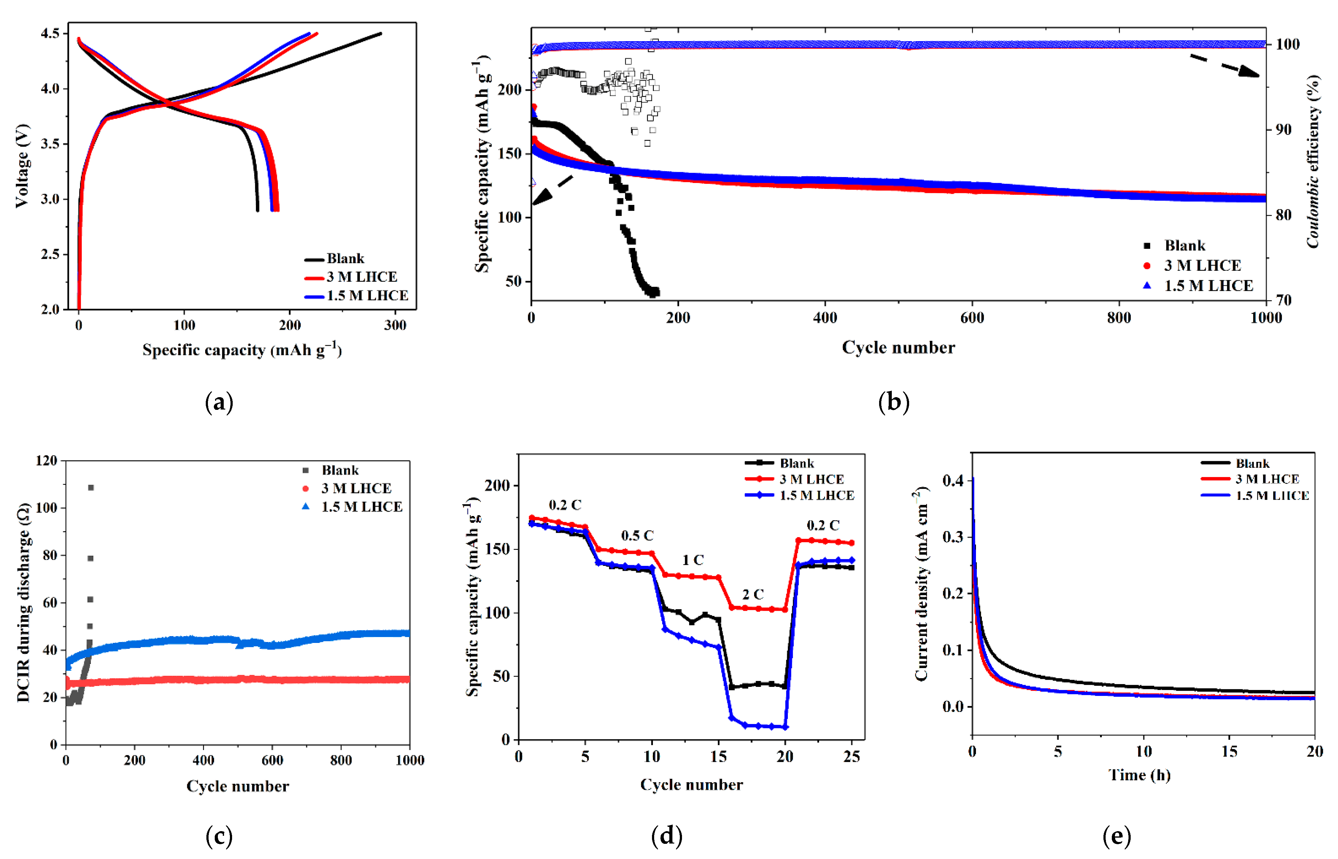
The electrochemical performance of the LCO//graphite cells with blank and LHCEs was investigated by galvanostatic charge and discharge steps. Figure 2a shows the initial charge/discharge curves of the LCO//graphite cells at 0.1 C in the voltage range of 2.9–4.5 V. The charge curves all present linear character, corresponding to a normal charging process of LCO. The cells using the blank, 3 M LHCE and 1.5 M LHCE electrolytes delivers specific charge capacities of 286.1, 225.4 and 218.3 mAh g−1, specific discharge capacities of 169.6, 188.7 and 183.2 mAh g−1, corresponding to initial Coulombic efficiencies (CEs) of 59.3%, 83.7% and 83.9%, respectively. The larger specific charge capacity and the lower CE of the cell using the blank electrolyte than those of the cells using the LHCEs indicate that the more decomposition of the electrolyte for the blank electrolyte, consuming extra Li ions via decomposition.
After formation cycles, the cells were cycled at 0.5 C in the range of 2.9–4.5 V to investigate the long-term cycling performance. As displayed in Figure 2b, the LCO//graphite cells with the LHCEs exhibit lower specific capacities in the initial 100 cycles compared to the cell using the blank electrolyte, which is attributed to the lower conductivity of the LHCEs. However, the poor stability of the blank electrolyte leads to the cell failure in 200 cycles, and the specific capacity drops down quickly to 40 mAh g−1 at 170th cycle. Instead, the cells using the LHCEs show extreme stability during 1000 cycles. The cells using the 3 M LHCE delivers an initial specific capacity of 160 mAh g−1 and maintains 113 mAh g−1 after 1000 cycles, which means a capacity retention of 70%. To evaluate the decomposition of electrolyte, the CE values of the cells upon cycling are also calculated and provided in Figure 2b. The CE values of the cell with the blank electrolyte are always lower than 97% and finally fluctuate randomly when capacity declines rapidly. In contrast, the CE values of the cells using the LHCEs are more than 99% after formation cycle, and even higher than 99.9% after 200 cycles, indicating an extraordinary stability during high-voltage cycling. Figure 2c demonstrates the advantage of using LHCEs via comparing the DCIR values of the cells using the blank, 3 M LHCE and 1.5 M LHCE electrolytes upon cycling. As can be seen, the resistance of the cell with the blank electrolyte increases fast after several cycles, and becomes more than 100 Ω in 200 cycles. In comparison, the resistance of the cell with the 3 M LHCE only grows from 26 Ω to 28 Ω after 1000 cycles. For the cell using the 1.5 M LHCE, the resistance change is from 35 Ω to 47 Ω. Since the generation of cathode electrolyte interphase (CEI) and solid electrolyte interphase (SEI) layers consumes more solvents than PF6 [22], the LHCEs with TTE are beyond limitation of solvation after formation cycles. It is noted that the resistance of the cell with the 1.5 M LHCE is always higher than that of the cell with the 3 M LHCE, which indicates that the stability of the former is inferior, corresponding to severer electrolyte decomposition or more precipitation of lithium salt.
The following experiment verifies the advantage of using the 3 M LHCE against using the 1.5 M LHCE, studying the rate capabilities of the cells using the different electrolytes. The cells were charged/discharged at 0.2, 0.5, 1 and 2 C with each rate for five cycles in the voltage range of 2.9–4.5 V, and returned to be charged/discharged at 0.2 C after the rate measurements. The results are shown in Figure 2d. For the cell using the blank electrolyte, the decomposition problem leads to poor performance as expected. This cell already delivers low specific capacities of below 100 mAh g−1 at 1 C, and less than 50 mAh g−1 at 2 C. After returning to 0.2 C, the specific capacities are also much lower than the values in the initial five cycles at 0.2 C. For the cell using the 1.5 M LHCE, the situation becomes even worse. When the rate is set as 1 C, it exhibits lower capacities compared to the cell using the blank electrolyte, and it has almost no capacity at 2 C. The specific capacities cannot be recovered to the original values when the rate is set back to 0.2 C. The even worse rate capability of the cell using the 1.5 M LHCE at higher rates of 1 and 2 C than the cell using the blank electrolyte is attributed to its lower ionic conductivity. Interestingly, the cell using the 3 M LHCE displays super rate capability as shown in Figure 2d, which has the highest specific capacities at different rates among the three kinds of cells. Though the viscosity of the 1.5 M LHCE is lower, the poorer stability of solvation structure with this concentration might lead to unexpected collapse and precipitation of lithium salt on the interface, especially at higher rates. The stability against oxidation of the three electrolytes was also confirmed by chronoamperometry measurements. After initial charge to 4.5 V, the chronoamperometry plots of the LCO//graphite cells using different electrolytes are demonstrated in Figure 2e. As can be seen, the leakage current of the cells using the LHCEs is about 50% lower than the cell with the blank electrolyte. From these electrochemical results, it can be concluded that the 3 M LHCE is the most promising formula, which could deliver moderate characters, thus presenting excellent electrochemical performance.
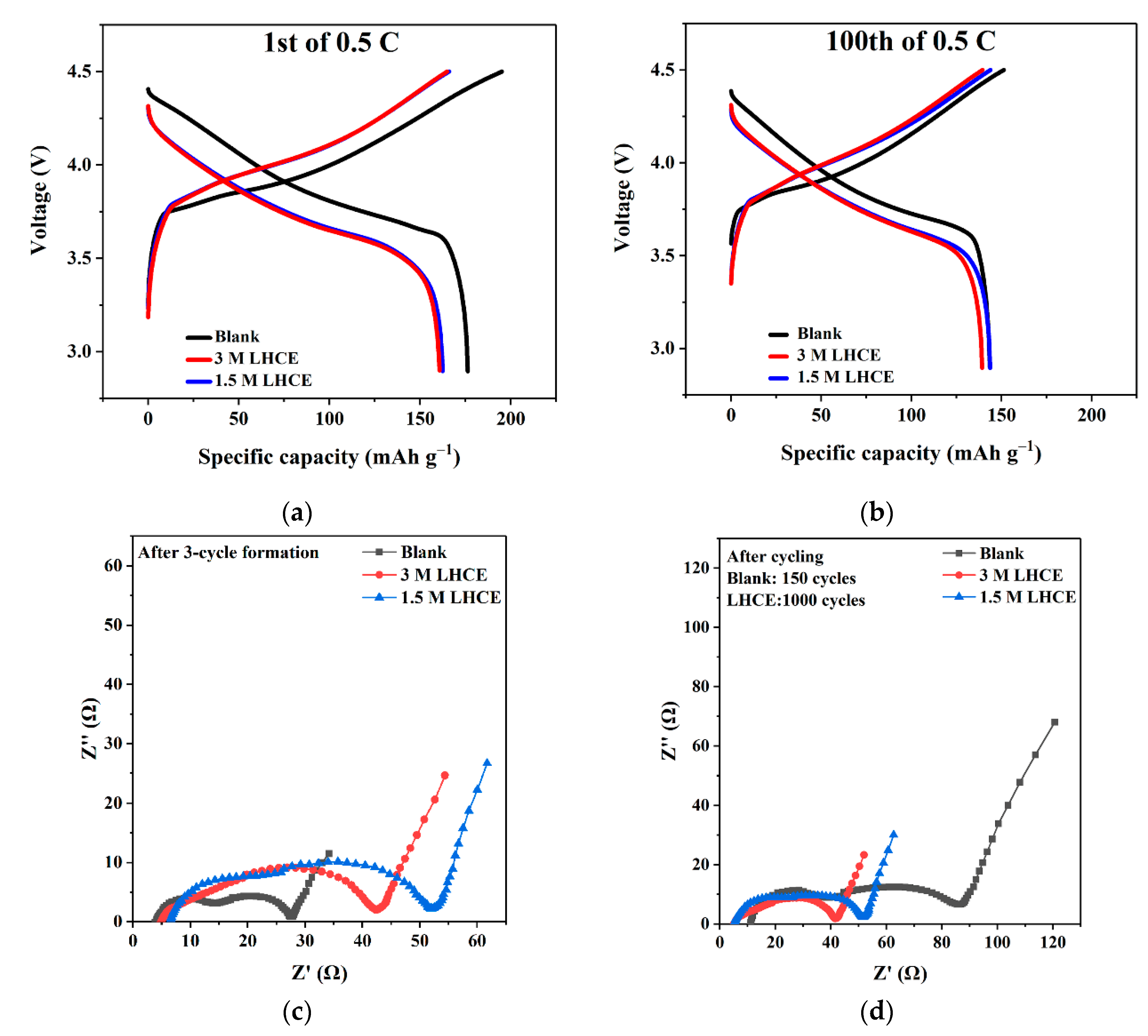
The initial and 100th charge and discharge curves of the cells using different electrolytes at 0.5 C in the voltage range of 2.9–4.5 V are drawn in Figure 3a,b, respectively. The cell with the blank electrolyte exhibits less polarization compared to the cells using the LHCEs in 100 cycles, due to its higher conductivity. Nevertheless, the difference of the polarization between the cells using the blank and LHCEs electrolytes becomes small after 100 cycles, and the cell with the blank electrolyte shows obvious increase of the polarization after 100 cycles. The results are also reflected from the cycling performance (Figure 2b) and the DCIR results (Figure 2c), in which the cell with the blank electrolyte exhibits stable cycling during initial cycles, and the rapid capacity fade occurs after several cycles. It is speculated that the onset of the capacity fade depends on the degree of the electrolyte decomposition. Moreover, the EIS results as shown in Figure 3c,d prove that although the cell with the blank electrolyte has the smallest impedance after the formation, it displays the largest impedance after 150 cycles, corresponding to the zone after the onset of the capacity fade. Note that the semicircles reflect interfacial resistance, the intercept of x axis is ohmic resistance, and the slope line behind corresponds to the diffusion resistance of Li+ ions [45]. After the formation, the cells using the LHCEs shower higher impedance than the cell using the blank electrolyte. While after cycling, the cells with the LHCEs display small interfacial impedance and negligible impedance change after 150 cycles, which indicates the LHCEs form thin and stable interfacial layers at 4.5 V for long cycling. In addition, the cell with the 3 M LHCE has smaller interfacial impedance than the cell with the 1.5 M LHCE, which proves again that the 3 M LHCE is the most outstanding formula.
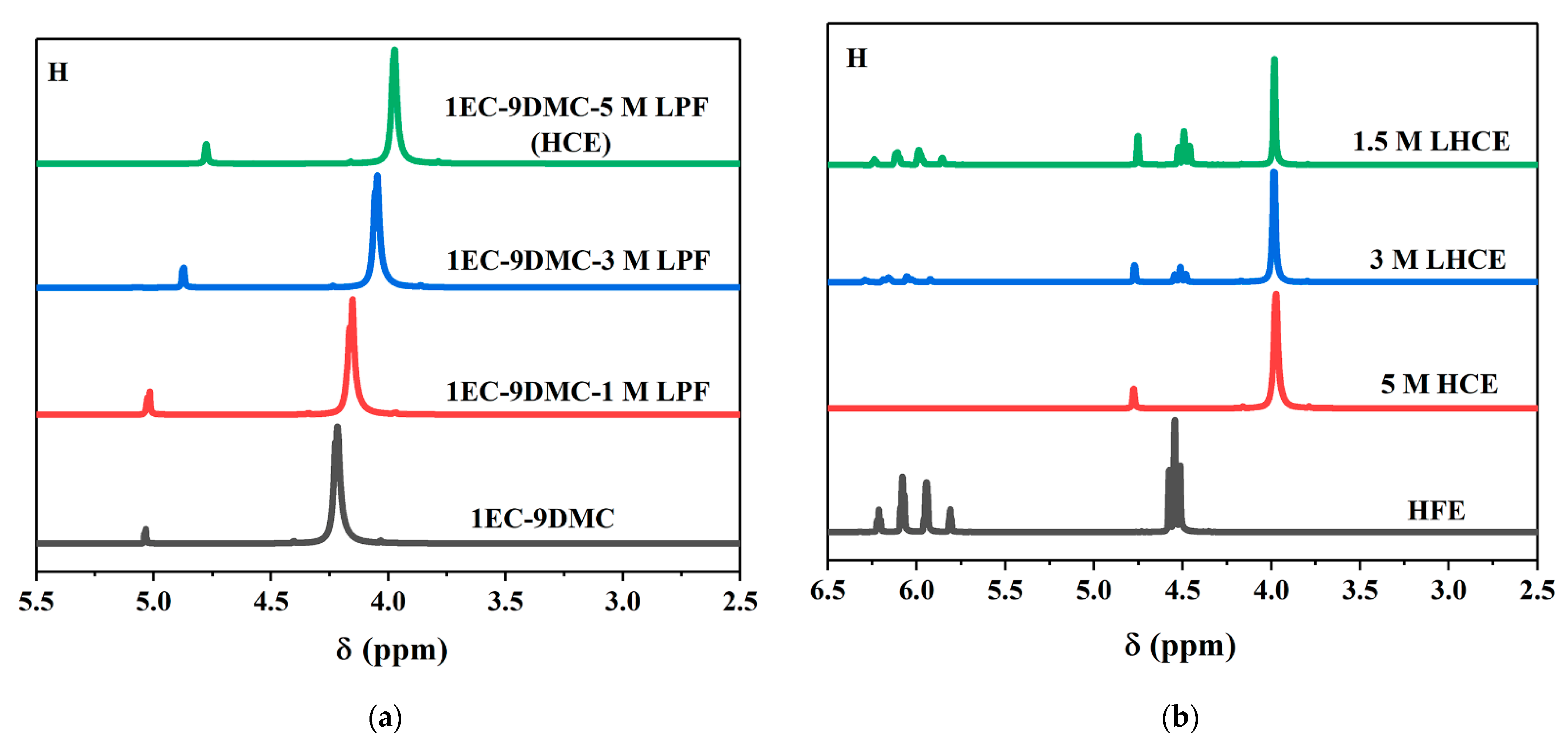
To understand the structure change after diluting, NMR was employed to depict the cooperation behaviors between Li+ ions and solvents. As shown in Figure 4a, the H peak of DMC at <4.5 ppm shifts to lower position when the salt concentration increases, indicating that the electric cloud of the solvent molecules is severely attracted by abundant Li+ ions. The peak of EC at >5 ppm shows no change when 1 M LiPF6 is used compared to the pure mixed solvents, but it starts to shift toward lower positions when more LiPF6 salts are added. After the addition of TTE, as shown in Figure 4b, the H peaks of DMC and EC in the 1.5 M LHCE and 3 M LHCE show the same position and intensity as in the 5M HCE, demonstrating that the addition of TTE does not influence the solvation structure of DMC and EC. Moreover, the H peaks of TTE in the LHCEs appear without obvious shift, proving that the participation of TTE in the solvation process outside the previous HCE solvation sheath.
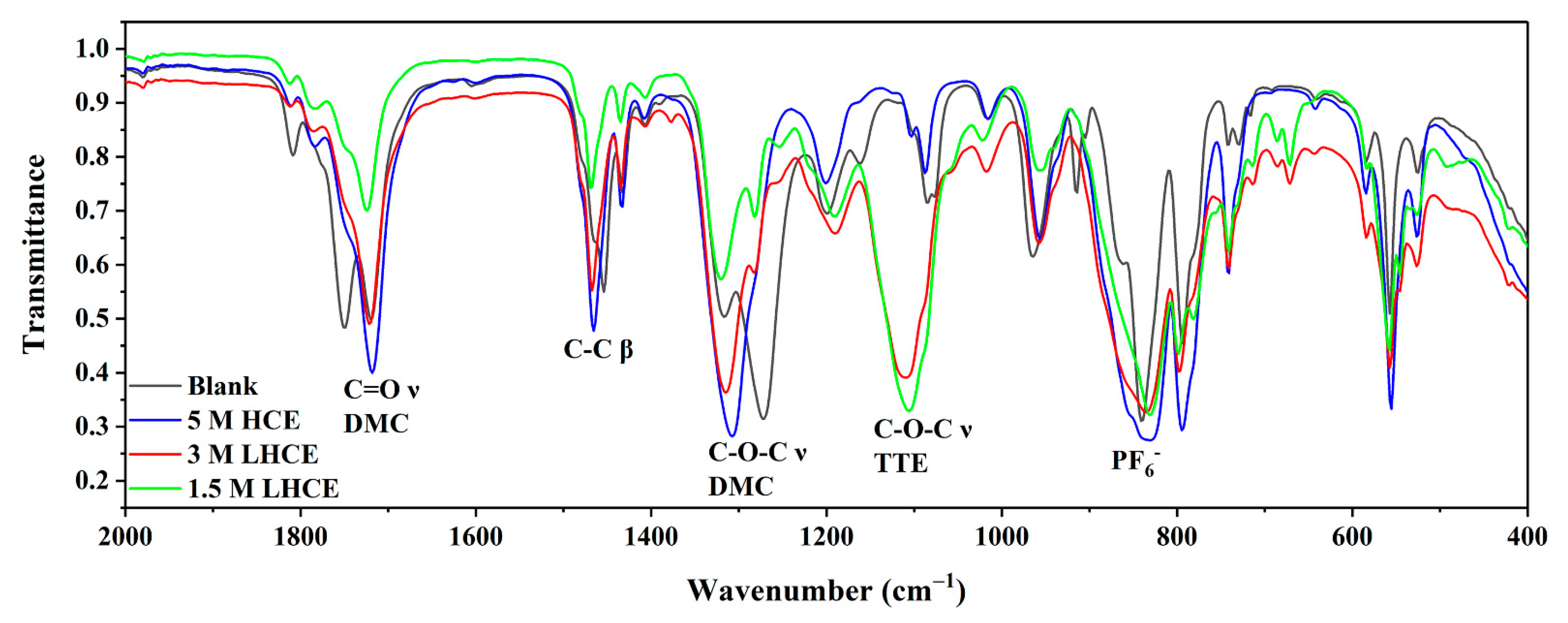
FTIR was also used to investigate the solvation structure of electrolytes. As shown in Figure 5, the stretch vibration peaks of C=O at 1750 cm−1 and 1720 cm−1 represent free DMC and solvated DMC, respectively. In the blank electrolyte, the peak at 1750 cm−1 is still obvious, but it becomes negligible in HCE and LHCEs. Similar situation occurs on the peak pair at 1270 cm−1 and 1307 cm−1 of C-O-C in DMC. Interestingly, the coordination of Li and DMC leads to blue shift here, which is opposite to the peaks of C=O. The in-plain bending vibration of C-C in DMC at 1454 cm−1 is also influenced by solvation, but the blue shift is only 13 cm−1 due to the group is far from Li+. The sharp peak at 839 cm−1 in the blank electrolyte is from free PF6. In HCE and LHCEs, the peak becomes broadened due to the contact ion pairs with PF6- in different chemical environments. The peak at 1105 cm−1 corresponds to the specific vibration of ether bond in TTE, and the peak of EC is not observed for its low proportion.
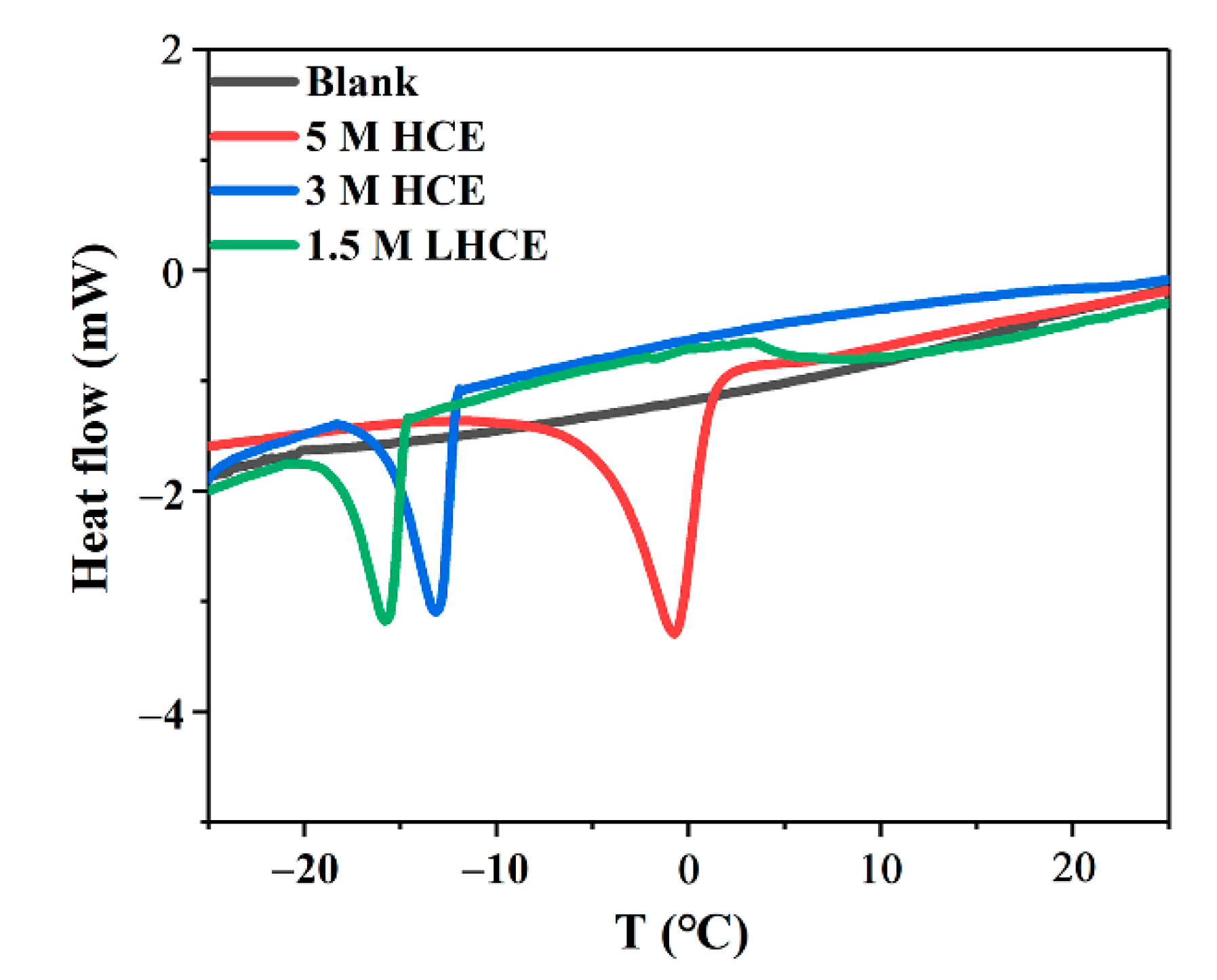
Owing to the high viscosity and melting point of HCE, the changes of thermal properties are also significant in the design of LHCEs. DSC was performed to investigate the freezing point of electrolytes, and the results are shown in Figure 6. As can be seen, the blank electrolyte has no peak from 25 °C to −25 °C for its low concentration, while a peak at 0 °C is observed for the 5 M HCE, corresponding to its freezing or precipitation point. In comparison, the peaks of the 3 M and 1.5 M LHCEs are −13 °C and −16 °C, respectively, which indicates the better low-temperature performance of LHCEs compared to the 5 M LHCE. Nevertheless, the low-temperature performance of LHCEs needs to be enhanced in the practical application.
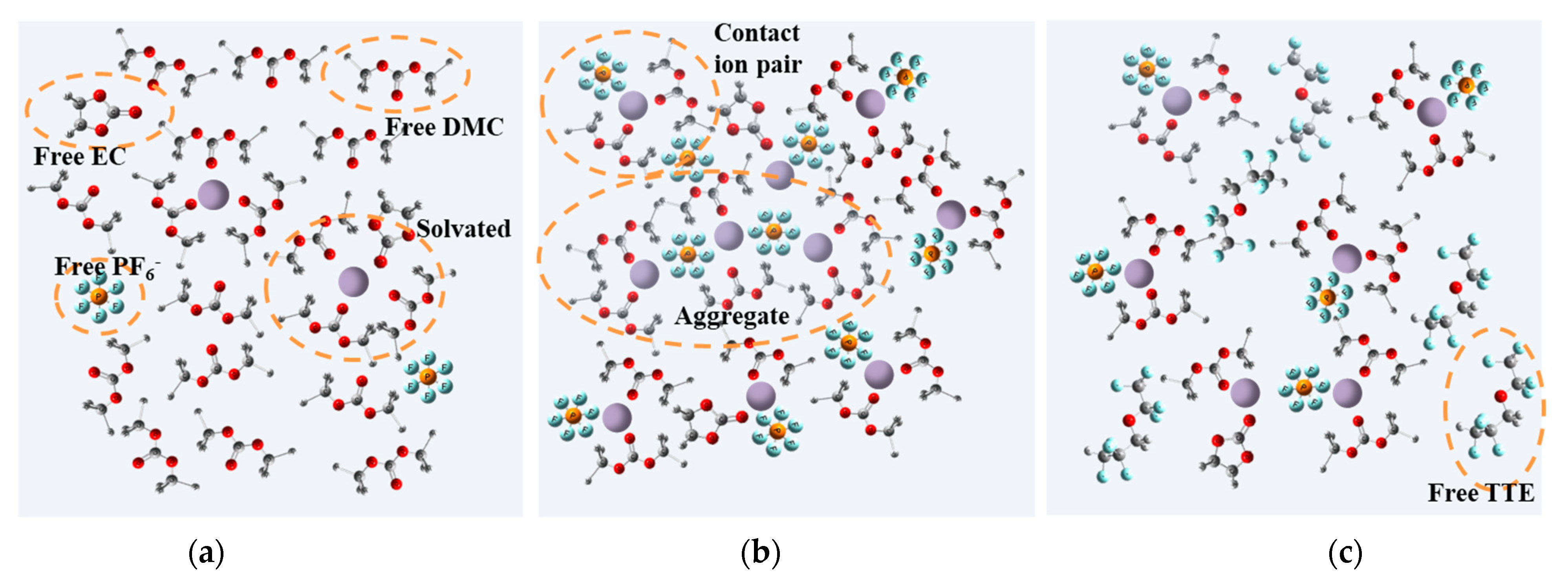
Figure 7 displays the structure illustrations of the solvent shells for the blank, 5 M HCE and 3 M LHCE electrolytes. In the blank electrolyte (Figure 7a), Li+ ions are fully coordinated, along with free negative ions and extra solvents. This structure allows low viscosity, but the abundant electrons of solvent are neutralized with Li ions, which leads to low oxidation voltage [22]. When the salt concentration increases to 5 M (Figure 7b), most Li+ ions have just one or two solvent molecules around, and the negative ions become pairs or aggregate with solvent shells. Though this structure improves stability, the absent of free solvents results in extremely high viscosity [30,46]. After TTE is added, it will not join into previous solvent’s shell for its poor compatibility. Instead, it becomes a lubricant between shells and finally decreases viscosity to an acceptable range [34].
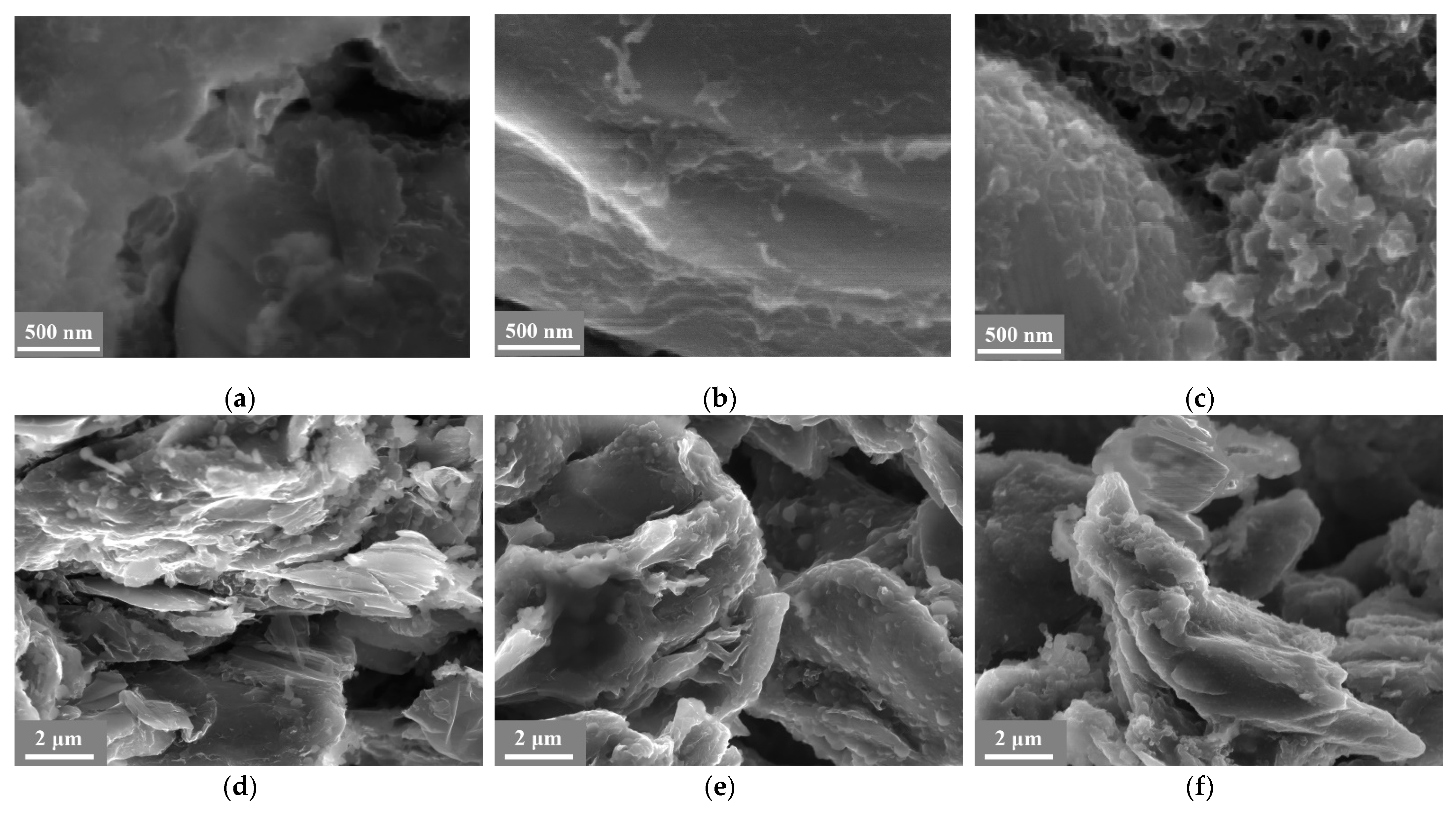
The corresponding explanations from microscale and surface components are also provided. Figure 8 presents the SEM images of the LCO cathodes and graphite anodes after cycling. As can be seen, the LCO cathode with the blank electrolyte presents thick and mossy interface after cycling at high voltage (Figure 8a). Instead, with 3 M LHCE, the surface of the LCO (Figure 8b) is cleaner and smoother, indicating less electrolyte decomposition. When the concentration of the LHCE drops down to 1.5 M, the surface becomes slightly rough and irregular. It is considered that after consumption of solvent during SEI/CEI formation, the solvent shell is not stable with a large amount of TTE. Similar results are also observed on the graphite anodes (Figure 8d–f). The graphite anodes with the blank electrolyte and 1.5 M LHCE exhibit a thicker and rougher surface, compared to that with the 3 M LHCE.
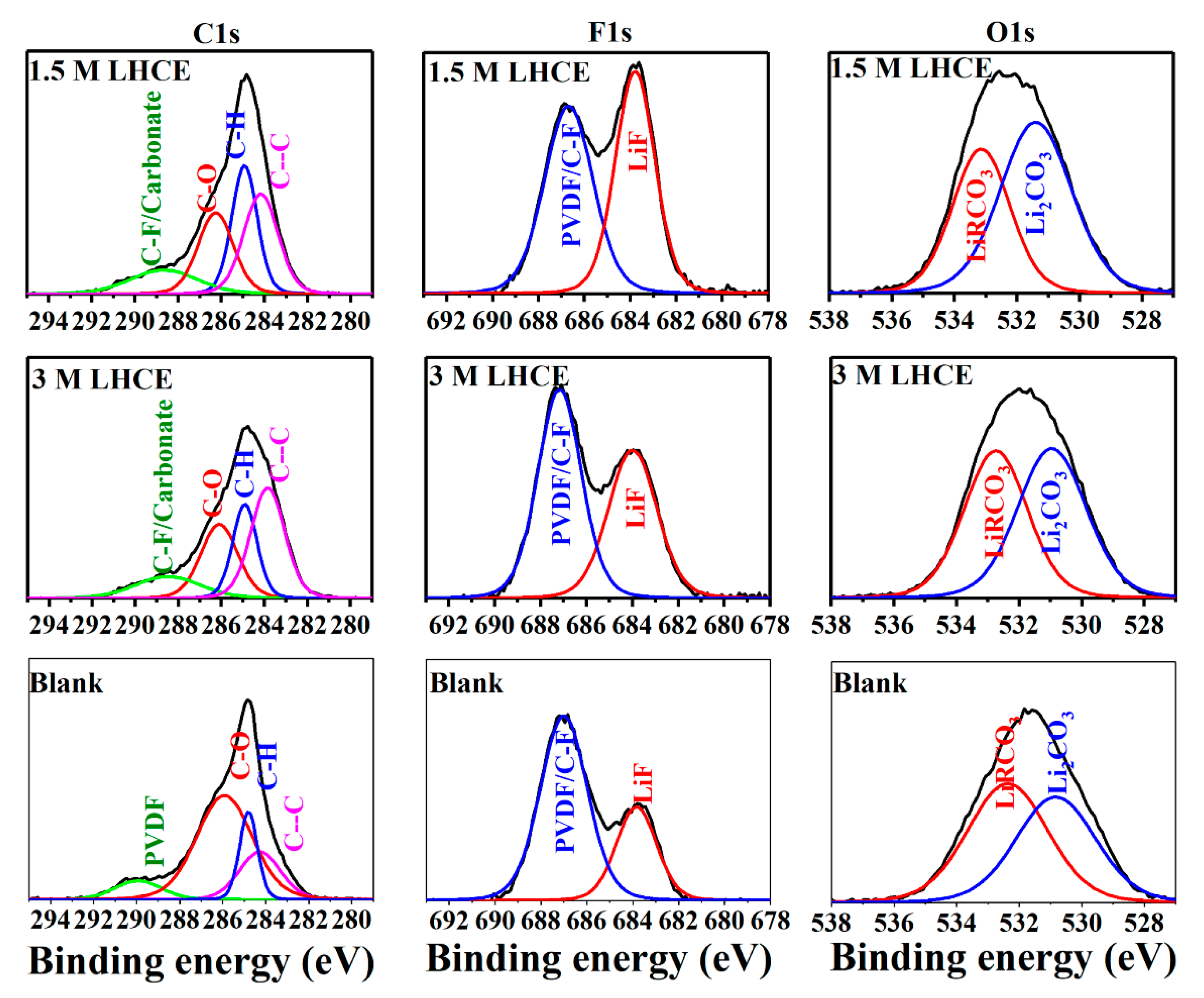
Figure 9 shows the C 1s, F 1s and O 1s XPS spectra of the LCO cathodes after cycling with different electrolytes. In the corresponding C1s spectra, the peaks of 290.2 eV and 288.2 eV represent F-C-F in PVDF and C=O band in the carbonates and organic layer, respectively [47,48]. The peak at 290.2 eV shifts to 289.0 eV with LHCEs, owing to H-C-F products from TTE. Instead, since less solvent generates fewer organic products with LHCEs [49,50], the C=O peak moves to similar position with H-C-F bond. The peak at 286.5 eV belongs to the C-O group of lithium alkyl carbonates [49,50,51]. The F1s spectra indicate more LiF could be formed on the surface due to some side reactions of TTE [22]. The moderate amount of LiF in the 3 M LHCE is believed to be beneficial for the improvement of the electrochemical performance [52], while excess LiF in the 1.5 M LHCE is not necessary. In O1s spectra, the peaks at 531.2 eV and 532.6 eV correspond to C=O and C-O of lithium alkyl carbonate, respectively, and the ratio of the two peaks slightly changes between the blank electrolyte and LHCEs, which is probably from the different participations of EC and DMC in the solvation when the concentration changes. Another small peak at 529.4 eV represents oxygen in LiCoO2. With LHCEs, the intensity of this peak drops down to less than 15% of the cathode using the blank electrolyte, indicating the formation of loose and incompact CEI layer using the blank electrolyte. Note that the absolute peak intensity here cannot be an indicator of concentration due to the free path of electrons in most CEI components is only about several nanometers, so that higher peaks of LiRCO3 and Li2CO3 with the LHCEs are possible. The C-O bond with the blank electrolyte may correspond to PEG, which is always on the outer layer of CEI [53]. Therefore, the massive PEG from the decomposition of electrolyte would impair the signals of inorganic components [54].
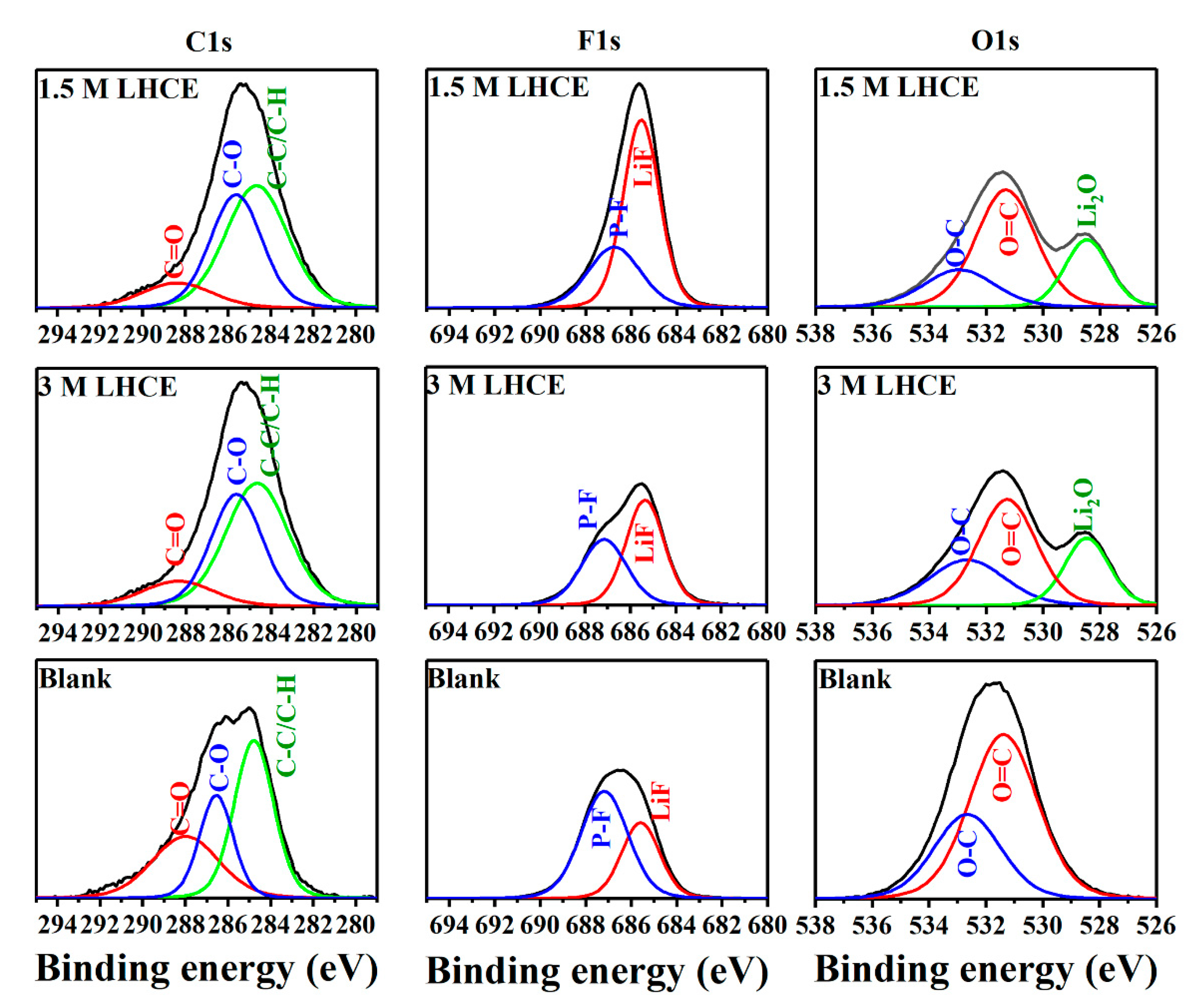
Figure 10 provides the C 1s, F 1s and O 1s XPS spectra of the graphite after cycling with different electrolytes. In C1s spectra, less intense C=O peaks of LHCEs reveal the reduction is also suppressed by this special solvent structure. The peak at 284.5 eV of C-C/C-H expands after LHCEs are introduced in, indicating an elastic polymer matrix component is generated, which would benefit for the cycling performance of graphite. In F1s spectra, higher LiF peaks at 685.3 eV are also observed in the LHCEs, which is similar to other previous results of LHCE, including α-HFEs [42] and β-HFEs [55]. In O1s spectra, an obvious peak of Li2O at 529.8 eV from sample with LHCEs suggests less decomposition of carbonates. Interestingly, this result corresponds to the spectra when VC additive is involved in [53], which forms a stable and effective SEI layer on anode with excellent performance in commercial application. Li2O has been proved as a vital part for preserving the electronic insulation characteristic of the SEI layer [56]. Therefore, our LHCEs designed for high voltage cathode also improve the property of SEI on graphite anode.

4. Conclusions

In the current study, a novel carbonate-based LHCE has been developed with the use of LiPF6 as Li salt and TTE as the counter solvent. By controlling the concentration as 3 M and a solvent ratio of EC:DMC:TTE = 1:9:8 in volume, the LHCE kept the solvent structure of HCEs well in the DMC/EC solvent, but showed a dramatically reduced viscosity. Consequently, the LCO//graphite full cells using the LHCE achieve an average coulombic efficiency as high as 99.9% and an extraordinary capacity retention of 70% after 1000 cycles at 0.5 C within 2.9 to 4.5 V. The outstanding electrochemical performance should be attributed to much enhanced interfacial stability with the assistance of TTE in LHCE, which has been well proved by electrochemical impedance spectra as well as the disassembled morphology and element measurements on both cathode and anode. This LHCE formula extends the study system, i.e., the choice of lithium salt and counter solvents to a new scope for the design of novel LHCEs for high voltage Li-based batteries.

Author Contributions

Conceptualization, X.M., P.Z. and J.W.; methodology, X.M. and P.Z.; software, X.M., P.Z., H.Z. and Y.Q.; validation, Q.W., G.Z., S.-S.C. and Z.L.; formal analysis, X.M., P.Z. and J.W.; investigation, X.M. and P.Z.; resources, J.W., C.W. and Y.D.; data curation, X.M. and P.Z.; writing—original draft preparation, X.M., P.Z. and J.W.; writing—review and editing, J.W., C.W. and Y.D.; visualization, X.M., P.Z. and J.W.; supervision, J.W., C.W. and Y.D.; project administration, J.W., C.W. and Y.D.; funding acquisition, J.W. and Y.D. All authors have read and agreed to the published version of the manuscript.

Funding

This research was funded by the Key-Area Research and Development Program of Guangdong Province (2020B090919001), Guangdong–Hong Kong–Macao Joint Laboratory for Photonic–Thermal–Electrical Energy Materials and Devices (2019B121205001), Guangdong Natural Science Foundation for Basic and Applied Basic Research (2021A1515010138), and Guangdong Basic and Applied Basic Research Foundation (2019A1515111030 and 2019B1515120028).

Institutional Review Board Statement

Not applicable.

Informed Consent Statement

Not applicable.

Data Availability Statement

Not applicable.

Acknowledgments

The authors acknowledge the support from the Materials Characterization and Preparation Center (MCPC) at Southern University of Science and Technology to perform physical characterizations.

Conflicts of Interest

The authors declare no conflict of interest.

References

  1. Winter, M.; Barnett, B.; Xu, K. Before Li Ion Batteries. Chem. Rev. 2018, 118, 11433–11456. [Google Scholar] [CrossRef] [PubMed]
  2. Liu, H.; Zhang, X.; He, X.; Senyshyn, A.; Wilken, A.; Zhou, D.; Fromm, O.; Niehoff, P.; Yan, B.; Li, J.; et al. Truncated Octahedral High-Voltage Spinel LiNi0.5Mn1.5O4 Cathode Materials for Lithium Ion Batteries: Positive Influences of Ni/Mn Disordering and Oxygen Vacancies. J. Electrochem. Soc. 2018, 165, A1886–A1896. [Google Scholar] [CrossRef]
  3. Liu, Y.; Hanai, K.; Yang, J.; Imanishi, N.; Hirano, A.; Takeda, Y. Silicon/carbon composites as anode materials for Li-ion batteries. Electrochem. Solid State Lett. 2004, 7, A369–A372. [Google Scholar] [CrossRef]
  4. Wong, D.P.; Tseng, H.-P.; Chen, Y.-T.; Hwang, B.-J.; Chen, L.-C.; Chen, K.-H. A stable silicon/graphene composite using solvent exchange method as anode material for lithium ion batteries. Carbon 2013, 63, 397–403. [Google Scholar] [CrossRef]
  5. Liu, Y.; Qin, L.; Liu, F.; Fan, Y.; Ruan, J.; Zhang, S. Interpenetrated 3D porous silicon as high stable anode material for Li-Ion battery. J. Power Sources 2018, 406, 167–175. [Google Scholar] [CrossRef]
  6. Liu, Y.; Sun, M.; Yuan, Y.; Wu, Q.; Wang, H.; He, Y.; Lin, Z.; Zhou, F.; Ling, M.; Qian, C.; et al. Accommodation of Silicon in an Interconnected Copper Network for Robust Li-Ion Storage. Adv. Funct. Mater. 2020, 30, 1910249. [Google Scholar] [CrossRef]
  7. Zheng, G.; Wang, C.; Pei, A.; Lopez, J.; Shi, F.; Chen, Z.; Sendek, A.D.; Lee, H.-W.; Lu, Z.; Schneider, H.; et al. High-Performance Lithium Metal Negative Electrode with a Soft and Flowable Polymer Coating. ACS Energy Lett. 2016, 1, 1247–1255. [Google Scholar] [CrossRef]
  8. Han, B.; Feng, D.; Li, S.; Zhang, Z.; Zou, Y.; Gu, M.; Meng, H.; Wang, C.; Xu, K.; Zhao, Y.; et al. Self-Regulated Phenomenon of Inorganic Artificial Solid Electrolyte Interphase for Lithium Metal Batteries. Nano Lett. 2020, 20, 4029–4037. [Google Scholar] [CrossRef]
  9. Louli, A.J.; Eldesoky, A.; Weber, R.; Genovese, M.; Coon, M.; deGooyer, J.; Deng, Z.; White, R.T.; Lee, J.; Rodgers, T.; et al. Diagnosing and correcting anode-free cell failure via electrolyte and morphological analysis. Nat. Energy 2020, 5, 693–702. [Google Scholar]
  10. Nanda, S.; Gupta, A.; Manthiram, A. Anode-Free Full Cells: A Pathway to High-Energy Density Lithium-Metal Batteries. Adv. Energy Mater. 2021, 11, 2000804. [Google Scholar] [CrossRef]
  11. Zhao, H.; Qian, Y.; Hu, S.; Luo, G.; Nie, C.; Qiu, P.; Kang, Y.; Wang, H.; Chu, Y.; Wang, Q.; et al. Tale of Three Phosphate Additives for Stabilizing NCM811/Graphite Pouch Cells: Significance of Molecular Structure–Reactivity in Dictating Interphases and Cell Performance. ACS Appl. Mater. Interfaces 2021, 13, 29676–29690. [Google Scholar] [CrossRef]
  12. Yi, T.-F.; Mei, J.; Zhu, Y.-R. Key strategies for enhancing the cycling stability and rate capacity of LiNi0.5Mn1.5O4 as high-voltage cathode materials for high power lithium-ion batteries. J. Power Sources 2016, 316, 85–105. [Google Scholar] [CrossRef]
  13. Risthaus, T.; Wang, J.; Friesen, A.; Wilken, A.; Berghus, D.; Winter, M.; Li, J. Synthesis of spinel LiNi0.5Mn1.5O4 with secondary plate morphology as cathode material for lithium ion batteries. J. Power Sources 2015, 293, 137–142. [Google Scholar] [CrossRef]
  14. Wang, J.; He, X.; Kloepsch, R.; Wang, S.; Hoffmann, B.; Jeong, S.; Yang, Y.; Li, J. Increased Capacity of LiNi1/3Co1/3Mn1/3O2–Li[Li1/3Mn2/3]O2 Cathodes by MnOx-surface Modification for Lithium-Ion Batteries. Energy Technol. 2014, 2, 188–193. [Google Scholar] [CrossRef]
  15. Qiu, B.; Zhang, Q.; Hu, H.; Wang, J.; Liu, J.; Xia, Y.; Zeng, Y.; Wang, X.; Liu, Z. Electrochemical investigation of Li-excess layered oxide cathode materials/mesocarbon microbead in 18650 batteries. Electrochim. Acta 2014, 123, 317–324. [Google Scholar] [CrossRef]
  16. Ma, X.; Wang, M.; Qian, Y.; Feng, D.; Zhang, G.; Xu, D.; Kang, Y.; Liu, Z.; Hu, S.; Zheng, J.; et al. Poly (methyl vinyl ether-alt-maleic anhydride) as an ecofriendly electrolyte additive for high-voltage lithium-rich oxides with improved stability of interphase. Electrochim. Acta 2021, 400, 139467. [Google Scholar] [CrossRef]
  17. Di Lecce, D.; Gancitano, V.; Hassoun, J. Investigation of Mn and Fe Substitution Effects on the Characteristics of High-Voltage LiCo1–xMxPO4 (x = 0.1, 0.4) Cathodes Prepared by Sol–gel Route. ACS Sustain. Chem. Eng. 2020, 8, 278–289. [Google Scholar] [CrossRef]
  18. Luong, H.D.; Dinh, V.A.; Momida, H.; Oguchi, T. Tavorite-like orthorhombic AxVPO4F (A = Li, Na) for novel high-voltage cathodes in rechargeable batteries. J. Alloys Compd. 2021, 875, 159963. [Google Scholar] [CrossRef]
  19. Pagot, G.; Bertasi, F.; Nawn, G.; Negro, E.; Carraro, G.; Barreca, D.; Maccato, C.; Polizzi, S.; Di Noto, V. High-Performance Olivine for Lithium Batteries: Effects of Ni/Co Doping on the Properties of LiFeαNiβCoγPO4 Cathodes. Adv. Funct. Mater. 2015, 25, 4032–4037. [Google Scholar] [CrossRef]
  20. Pagot, G.; Bandiera, M.; Vezzù, K.; Migliori, A.; Bertoncello, R.; Negro, E.; Morandi, V.; Di Noto, V. High valence transition metal-doped olivine cathodes for superior energy and fast cycling lithium batteries. J. Mater. Chem. A 2020, 8, 25727–25738. [Google Scholar] [CrossRef]
  21. Xu, K. Nonaqueous liquid electrolytes for lithium-based rechargeable batteries. Chem. Rev. 2004, 104, 4303–4417. [Google Scholar] [CrossRef]
  22. Xu, K. Electrolytes and Interphases in Li-Ion Batteries and Beyond. Chem. Rev. 2014, 114, 11503–11618. [Google Scholar] [CrossRef]
  23. Zheng, X.; Huang, T.; Pan, Y.; Wang, W.; Fang, G.; Wu, M. High-voltage performance of LiNi1/3Co1/3Mn1/3O2/graphite batteries with di(methylsulfonyl) methane as a new sulfone-based electrolyte additive. J. Power Sources 2015, 293, 196–202. [Google Scholar] [CrossRef]
  24. Lan, J.; Zheng, Q.; Zhou, H.; Li, J.; Xing, L.; Xu, K.; Fan, W.; Yu, L.; Li, W. Stabilizing a High-Voltage Lithium-Rich Layered Oxide Cathode with a Novel Electrolyte Additive. ACS Appl. Mater. Interfaces 2019, 11, 28841–28850. [Google Scholar] [CrossRef] [PubMed]
  25. Lee, T.J.; Soon, J.; Chae, S.; Ryu, J.H.; Oh, S.M. A Bifunctional Electrolyte Additive for High-Voltage LiNi0.5Mn1.5O4 Positive Electrodes. ACS Appl. Mater. Interfaces 2019, 11, 11306–11316. [Google Scholar] [CrossRef] [PubMed]
  26. Kang, Y.; Wang, J.; Du, L.; Liu, Z.; Zou, X.; Tang, X.; Cao, Z.; Wang, C.; Xiong, D.; Shi, Q.; et al. Overcharge Investigations of LiCoO2/Graphite Lithium Ion Batteries with Different Electrolytes. ACS Appl. Energy Mater. 2019, 2, 8615–8624. [Google Scholar] [CrossRef]
  27. Brutti, S.; Simonetti, E.; De Francesco, M.; Sarra, A.; Paolone, A.; Palumbo, O.; Fantini, S.; Lin, R.; Falgayrat, A.; Choi, H.; et al. Ionic liquid electrolytes for high-voltage, lithium-ion batteries. J. Power Sources 2020, 479, 228791. [Google Scholar] [CrossRef]
  28. Hu, Z.; Xian, F.; Guo, Z.; Lu, C.; Du, X.; Cheng, X.; Zhang, S.; Dong, S.; Cui, G.; Chen, L. Nonflammable Nitrile Deep Eutectic Electrolyte Enables High-Voltage Lithium Metal Batteries. Chem. Mater. 2020, 32, 3405–3413. [Google Scholar] [CrossRef]
  29. Doi, T.; Shimizu, Y.; Hashinokuchi, M.; Inaba, M. Dilution of Highly Concentrated LiBF4/Propylene Carbonate Electrolyte Solution with Fluoroalkyl Ethers for 5-V LiNi0.5Mn1.5O4 Positive Electrodes. J. Electrochem. Soc. 2017, 164, A6412–A6416. [Google Scholar] [CrossRef]
  30. Liu, Q.; Xu, H.; Wu, F.; Mu, D.; Shi, L.; Wang, L.; Bi, J.; Wu, B. Effects of a High-Concentration LiPF6-Based Carbonate Ester Electrolyte for the Electrochemical Performance of a High-Voltage Layered LiNi0.6Co0.2Mn0.2O2 Cathode. ACS Appl. Energy Mater. 2019, 2, 8878–8884. [Google Scholar] [CrossRef]
  31. McOwen, D.W.; Seo, D.M.; Borodin, O.; Vatamanu, J.; Boyle, P.D.; Henderson, W.A. Concentrated electrolytes: Decrypting electrolyte properties and reassessing Al corrosion mechanisms. Energy Environ. Sci. 2014, 7, 416–426. [Google Scholar] [CrossRef]
  32. Xia, L.; Yu, L.; Hu, D.; Chen, Z.G. Research Progress and Perspectives on High Voltage, Flame Retardant Electrolytes for Lithium-Ion Batteries. Acta Chim. Sin. 2017, 75, 1183–1195. [Google Scholar] [CrossRef]
  33. Zheng, J.; Chen, S.; Zhao, W.; Song, J.; Engelhard, M.H.; Zhang, J.-G. Extremely Stable Sodium Metal Batteries Enabled by Localized High-Concentration Electrolytes. ACS Energy Lett. 2018, 3, 315–321. [Google Scholar] [CrossRef]
  34. Chen, S.; Zheng, J.; Yu, L.; Ren, X.; Engelhard, M.H.; Niu, C.; Lee, H.; Xu, W.; Xiao, J.; Liu, J.; et al. High-Efficiency Lithium Metal Batteries with Fire-Retardant Electrolytes. Joule 2018, 2, 1548–1558. [Google Scholar] [CrossRef] [Green Version]
  35. Jie, Y.; Ren, X.; Cao, R.; Cai, W.; Jiao, S. Advanced Liquid Electrolytes for Rechargeable Li Metal Batteries. Adv. Funct. Mater. 2020, 30, 1910777. [Google Scholar] [CrossRef]
  36. Ren, X.; Zou, L.; Cao, X.; Engelhard, M.H.; Liu, W.; Burton, S.D.; Lee, H.; Niu, C.; Matthews, B.E.; Zhu, Z.; et al. Enabling High-Voltage Lithium-Metal Batteries under Practical Conditions. Joule 2019, 3, 1662–1676. [Google Scholar] [CrossRef]
  37. Ma, G.; Wang, L.; He, X.; Zhang, J.; Chen, H.; Xu, W.; Ding, Y. Pseudoconcentrated Electrolyte with High Ionic Conductivity and Stability Enables High-Voltage Lithium-Ion Battery Chemistry. ACS Appl. Energy Mater. 2018, 1, 5446–5452. [Google Scholar] [CrossRef]
  38. Chen, S.; Zheng, J.; Mei, D.; Han, K.S.; Engelhard, M.H.; Zhao, W.; Xu, W.; Liu, J.; Zhang, J.-G. High-Voltage Lithium-Metal Batteries Enabled by Localized High-Concentration Electrolytes. Adv. Mater. 2018, 30, 1706102. [Google Scholar] [CrossRef] [PubMed]
  39. Zheng, Y.; Soto, F.A.; Ponce, V.; Seminario, J.M.; Cao, X.; Zhang, J.-G.; Balbuena, P.B. Localized high concentration electrolyte behavior near a lithium–metal anode surface. J. Mater. Chem. A 2019, 7, 25047–25055. [Google Scholar] [CrossRef]
  40. Cao, X.; Jia, H.; Xu, W.; Zhang, J.-G. Review—Localized High-Concentration Electrolytes for Lithium Batteries. J. Electrochem. Soc. 2021, 168, 010522. [Google Scholar] [CrossRef]
  41. Dai, W.; Dong, N.; Xia, Y.; Chen, S.; Luo, H.; Liu, Y.; Liu, Z. Localized concentrated high-concentration electrolyte enhanced stability and safety for high voltage Li-ion batteries. Electrochim. Acta 2019, 320, 134633. [Google Scholar] [CrossRef]
  42. Piao, N.; Ji, X.; Xu, H.; Fan, X.; Chen, L.; Liu, S.; Garaga, M.N.; Greenbaum, S.G.; Wang, L.; Wang, C.; et al. Countersolvent Electrolytes for Lithium-Metal Batteries. Adv. Energy Mater. 2020, 10, 1903568. [Google Scholar] [CrossRef]
  43. Su, C.C.; He, M.; Amine, R.; Amine, K. A Selection Rule for Hydrofluoroether Electrolyte Cosolvent: Establishing a Linear Free-Energy Relationship in Lithium-Sulfur Batteries. Angew. Chem. Int. Ed. 2019, 58, 10591–10595. [Google Scholar] [CrossRef]
  44. Ren, X.D.; Chen, S.R.; Lee, H.; Mei, D.H.; Engelhard, M.H.; Burton, S.D.; Zhao, W.G.; Zheng, J.M.; Li, Q.Y.; Ding, M.S.; et al. Localized High-Concentration Sulfone Electrolytes for High-Efficiency Lithium-Metal Batteries. Chem 2018, 4, 1877–1892. [Google Scholar] [CrossRef] [Green Version]
  45. Ma, X.; Feng, D.; Xiao, Y.; Qian, Y.; Wang, Q.; Kang, Y.; Xu, D.; Zhao, H.; Xu, H.; Yi, H.; et al. Generating lithium fluoride-abundant interphase on layered lithium-rich oxide cathode with lithium 1,1,2,2,3,3-hexafluoropropane-1,3-disulfonimide. J. Power Sources 2021, 507, 230278. [Google Scholar] [CrossRef]
  46. Yamada, Y.; Chiang, C.H.; Sodeyama, K.; Wang, J.H.; Tateyama, Y.; Yamada, A. Corrosion Prevention Mechanism of Aluminum Metal in Superconcentrated Electrolytes. ChemElectroChem 2015, 2, 1687–1694. [Google Scholar] [CrossRef]
  47. Tan, S.; Zhang, Z.; Li, Y.; Li, Y.; Zheng, J.; Zhou, Z.; Yang, Y. Tris(hexafluoro-iso-propyl)phosphate as an SEI-Forming Additive on Improving the Electrochemical Performance of the Li[Li0.2Mn0.56Ni0.16Co0.08]O2Cathode Material. J. Electrochem. Soc. 2012, 160, A285–A292. [Google Scholar] [CrossRef]
  48. Pham, H.Q.; Nam, K.-M.; Hwang, E.-H.; Kwon, Y.-G.; Jung, H.M.; Song, S.-W. Performance Enhancement of 4.8 V Li1.2Mn0.525Ni0.175Co0.1O2Battery Cathode Using Fluorinated Linear Carbonate as a High-Voltage Additive. J. Electrochem. Soc. 2014, 161, A2002–A2011. [Google Scholar] [CrossRef]
  49. Li, J.; Xing, L.; Zhang, R.; Chen, M.; Wang, Z.; Xu, M.; Li, W. Tris(trimethylsilyl)borate as an electrolyte additive for improving interfacial stability of high voltage layered lithium-rich oxide cathode/carbonate-based electrolyte. J. Power Sources 2015, 285, 360–366. [Google Scholar] [CrossRef]
  50. Hong, P.; Xu, M.; Zheng, X.; Zhu, Y.; Liao, Y.; Xing, L.; Huang, Q.; Wan, H.; Yang, Y.; Li, W. Effect of ethylene glycol bis (propionitrile) ether (EGBE) on the performance and interfacial chemistry of lithium-rich layered oxide cathode. J. Power Sources 2016, 329, 216–224. [Google Scholar] [CrossRef]
  51. Wang, S.; Dai, A.; Cao, Y.; Yang, H.; Khalil, A.; Lu, J.; Li, H.; Ai, X. Enabling stable and high-rate cycling of a Ni-rich layered oxide cathode for lithium-ion batteries by modification with an artificial Li+-conducting cathode-electrolyte interphase. J. Mater. Chem. A 2021, 9, 11623–11631. [Google Scholar] [CrossRef]
  52. Xiao, Y.; Han, B.; Zeng, Y.; Chi, S.-S.; Zeng, X.; Zheng, Z.; Xu, K.; Deng, Y. New Lithium Salt Forms Interphases Suppressing Both Li Dendrite and Polysulfide Shuttling. Adv. Energy Mater. 2020, 10, 1903937. [Google Scholar] [CrossRef]
  53. Qian, Y.; Hu, S.; Zou, X.; Deng, Z.; Xu, Y.; Cao, Z.; Kang, Y.; Deng, Y.; Shi, Q.; Xu, K.; et al. How electrolyte additives work in Li-ion batteries. Energy Storage Mater. 2019, 20, 208–215. [Google Scholar] [CrossRef]
  54. Niehoff, P.; Passerini, S.; Winter, M. Interface Investigations of a Commercial Lithium Ion Battery Graphite Anode Material by Sputter Depth Profile X-ray Photoelectron Spectroscopy. Langmuir 2013, 29, 5806–5816. [Google Scholar] [CrossRef] [PubMed]
  55. Jia, H.; Zou, L.; Gao, P.; Cao, X.; Zhao, W.; He, Y.; Engelhard, M.H.; Burton, S.D.; Wang, H.; Ren, X.; et al. High-Performance Silicon Anodes Enabled by Nonflammable Localized High-Concentration Electrolytes. Adv. Energy Mater. 2019, 9, 1900784. [Google Scholar] [CrossRef]
  56. Han, B.; Zou, Y.; Xu, G.; Hu, S.; Kang, Y.; Qian, Y.; Wu, J.; Ma, X.; Yao, J.; Li, T.; et al. Additive stabilization of SEI on graphite observed using cryo-electron microscopy. Energy Environ. Sci. 2021, 14, 4882–4889. [Google Scholar] [CrossRef]
Figure 1. (a) Viscosity of LiPF6/EC/DMC electrolytes (blank line) and LiPF6/EC/DMC/TTE electrolytes; (b) Conductivity of LiPF6/EC/DMC electrolytes (blank line) and LiPF6/EC/DMC/TTE electrolytes; (c) LSV curves of the blank electrolyte, 5 M HCE, 3 M LHCE and 1.5 M LHCE.
Liquids 01 00005 g001
Figure 2. (a) Initial charge and discharge curves of the LCO//graphite cells with the blank, 3 M LHCE and 1.5 M LHCE electrolytes; (b) Cycling performance of the LCO//graphite cells using the blank, 3 M LHCE and 1.5 M LHCE electrolytes at 0.5 C and 30 °C in the voltage range of 2.9–4.5 V; (c) DCIR results of the LCO//graphite cells with the blank, 3 M LHCE and 1.5 M LHCE electrolytes upon cycling; (d) Rate capabilities of the LCO//graphite cells with the blank, 3 M LHCE and 1.5 M LHCE electrolytes at 30 °C; (e) Chronoamperometry plots of the LCO//graphite cells with the blank, 3 M LHCE and 1.5 M LHCE electrolytes at a charged state of 4.5 V.
Liquids 01 00005 g002
Figure 3. (a) Initial charge and discharge curves of the LCO//graphite cells with the blank, 3 M LHCE and 1.5 M LHCE electrolytes at 0.5 C in the voltage range of 2.9–4.5 V; (b) The 100th charge and discharge curves of the LCO//graphite cells with different electrolytes; (c) Nyquist diagrams of the LCO//graphite cells with different electrolytes after formation cycles; (d) Nyquist diagrams of these cells after 150 cycles (blank) and 1000 cycles (LHCEs).
Liquids 01 00005 g003
Figure 4. (a) NMR spectra of electrolytes with different amounts of LiPF6 in EC/DMC; (b) NMR spectra of pure TTE, and different LHCEs diluted from 5 M HCE of LiPF6/EC/DMC.
Liquids 01 00005 g004
Figure 5. FTIR spectra of blank electrolyte, 5 M HCE, 3 M LHCE and 1.5 M LHCE.
Liquids 01 00005 g005
Figure 6. DSC curves of blank electrolyte, 5 M HCE, 3 M LHCE and 1.5 M LHCE.
Liquids 01 00005 g006
Figure 7. (a) Illustration of the solvation structure for the blank electrolyte; (b) Illustration of the solvation structure for the 5 M HCE; (c) Illustration of the solvation structure for the 3 M LHCE.
Liquids 01 00005 g007
Figure 8. SEM images of the LCO cathodes after cycling with (a) the blank electrolyte, (b) 3 M LHCE and (c) 1.5 M LHCE; SEM images of the graphite anodes after cycling with (d) the blank electrolyte and (e) 3 M LHCE and (f) 1.5 M LHCE.
Liquids 01 00005 g008
Figure 9. XPS spectra of C 1s, F 1s and O 1s of the LCO cathodes after cycling with different electrolytes.
Liquids 01 00005 g009
Figure 10. XPS spectra of C 1s, F 1s and O 1s of the graphite anodes after cycling with different electrolytes.
Liquids 01 00005 g010
Publisher’s Note: MDPI stays neutral with regard to jurisdictional claims in published maps and institutional affiliations.