Review

A Historical Review of Impressed Current Cathodic Protection of Steel in Concrete

by
John P. Broomfield
Broomfield Consultants, 30B Vine Rd, East Molesey, Surrey KT8 9LF, UK
Constr. Mater. 2021, 1(1), 1-21; https://doi.org/10.3390/constrmater1010001
Submission received: 16 October 2020 / Revised: 12 November 2020 / Accepted: 23 November 2020 / Published: 9 December 2020

Abstract

:
This paper reviews the history of the development of impressed current cathodic protection of atmospherically exposed reinforced concrete from the first trials in 1959 on bridges to recently installed systems on a wide range of structures around the world. The paper covers the research efforts, anode developments, control systems and monitoring sensors which are reviewed and their evolution explained. The research into the potential and actual side effects of cathodic protection currents in concrete are summarised. The development of standards and guidance on impressed current cathodic protection is also reviewed.

1. Introduction

The corrosion of reinforcing steel in concrete has developed into one of the biggest durability issues for reinforced concrete structures. Impressed current cathodic protection (ICCP) was developed as a method for controlling this problem and extending the life of reinforced concrete. The background to our understanding of the problem of the corrosion of steel in concrete, its investigation and repair options are discussed elsewhere, e.g., see Broomfield [1]. This paper reviews the author’s involvement in and understanding of the history and development of ICCP for atmospherically exposed reinforced-concrete structures, with some of the key papers in that development process.

2. Historical Development

Cathodic protection (CP) of metals in sea water was first reported in 1824, by Humphry Davy [2]. However, it was not very successful in the application for which it was developed. In the early 1940s CP was applied to an old natural gas piping network that had been developing leaks at a rapidly increasing rate, to the point where the owner considered abandoning it. The observed reduction in the number of leaks immediately after the CP installation was considered impressive. A similarly substantial reduction in the frequency of leaks on a cast iron water main was achieved at about the same time. Modern specifications for the cathodic protection of active ocean-going ships were first described in 1950 [3].
The earliest applications of cathodic protection to reinforced concrete were to prestressed concrete water pipelines, see for example Unz [4] and Heuze [5], with reported applications before 1955 to buried reinforced concrete water tanks, steel reinforcement and linings of nuclear reactor containment vessels and concrete coated piling, see Vrable [6]. Most of the early applications relate to reinforced concrete buried in soils. Such applications allowed the use of conventional buried pipeline cathodic protection design principles and anode systems.
The first major step toward impressed current cathodic protection (ICCP) of atmospherically exposed reinforced concrete occurred in the USA as early as 1959 when Stratfull [7] applied a trial system to bridge beams and pile caps on the seven mile long San Mateo-Hayward Bridge in San Francisco Bay. This required a departure from conventional buried and submerged anode systems, with novel anode designs applied directly to the concrete surface.
Between the first full bridge deck installation in 1973, also reported by Stratfull [8,9], and 1989, a total of 287 systems were installed on US interstate highway bridges according to Broomfield [10], predominantly on bridge decks suffering from de-icing salt attack, although a number of substructure systems were also being installed in North America [11]. Many more systems were also applied to other structures as well as to additional bridges outside the US interstate system.
The initial development of ICCP in North America was due to the fact that the USA and Canada did not adopt the practice of applying waterproofing membranes to highway bridge decks, as was more common in Northern Europe and other areas where chloride based de-icing salts were used extensively [12]. Potholing of bridge decks due to reinforcement corrosion became a major problem in North America and ICCP was developed as a cost-effective strategy for extending bridge deck life. Although the lack of a membrane and overlay led to chloride ingress and reinforcement corrosion, it also meant it was straightforward to apply an ICCP anode system to the bare concrete bridge deck.
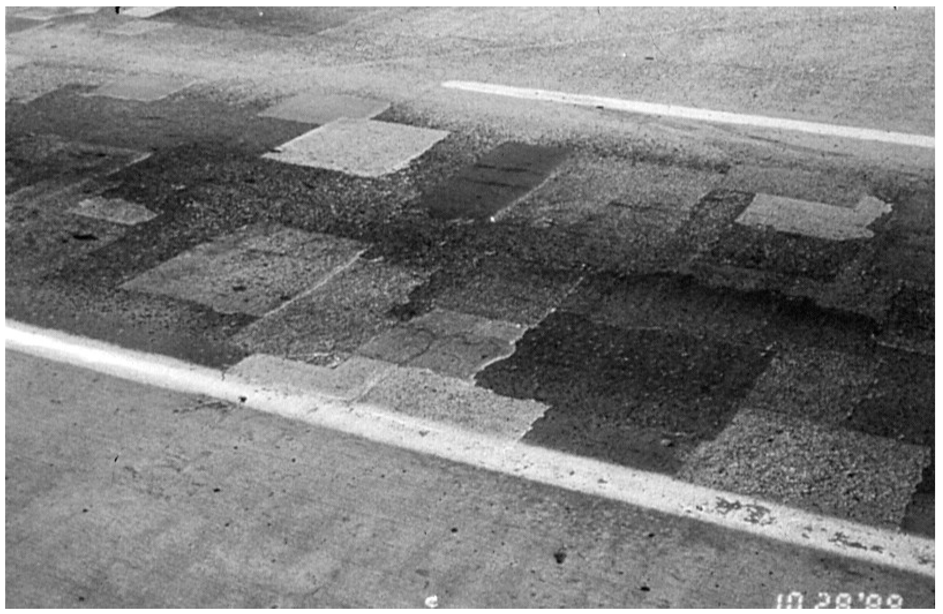
The “incipient anode” effect was identified as leading to the early failure of patch repairs where the problem was chloride-induced reinforcement corrosion [13]. This occurs because an actively corroding anode can be effectively cathodically protecting steel around it, even if the local chloride level is at or above the threshold for corrosion. When corrosion induced damage occurs and the anode area is repaired, the chloride-contaminated concrete is replaced with new, uncontaminated concrete so the previous anode becomes a cathode. This encourages the area around to become anodic and start corroding as shown in Figure 1. This leads to cracking and spalling of concrete around the patch [14].
An example of the sequential patching caused by this effect on a US bridge deck is shown in Figure 2. A cathodic protection system can control corrosion across the area where the anode is installed, while alternatives, such as coatings, were demonstrated to be ineffective in controlling chloride-induced corrosion as found by researchers at Aston University UK [15]. Similarly, in the USA, Federal Highway Administration (FHWA) sponsored research found that “the use of overlays, waterproof membranes and sealers only serve to slow the corrosion rate. On the other hand, CP has proven to be successful in retarding and controlling chloride-induced corrosion in reinforced concrete” [16].
In the UK, the initial interest in ICCP was the protection of bridge substructures where salt leakage from the waterproofed decks leads to corrosion, the waterproofing having minimised chloride ingress and corrosion and also making it difficult to install anodes on decks. In a survey, over 20% of a sample of 400 bridges were found to be suffering from reinforcement corrosion, primarily due to deicing salt ingress [17]. Some of the earliest applications of ICCP systems to reinforced-concrete buildings were in the UK. In some cases, a calcium chloride set accelerator had been added to the concrete mix in the 1960s construction boom, leading to corrosion rather than deicing salt or sea salt ingress [18]. Also, structures exposed on or near the sea front were identified as needing protection [19]. The initial UK research and development efforts, therefore, concentrated on conductive coating anodes for vertical and soffit applications. Early installations on reinforced concrete structures exposed to sea salt were also conducted in Australia [18].

3. Research Projects

Subsequent to Stratfull’s original research at the California Department of Transportation, the biggest single research project on ICCP for atmospherically exposed reinforced concrete was the Strategic Highway Research Program (SHRP), set up by the National Academy of Science and funded by the US State Highway Agencies and the Canadian Provincial Highway Agencies. This ran between 1987 and 1992 and spent approximately $150 million on concrete, asphalt, long-term pavement performance and maintenance. SHRP spent $10 million on the investigation and rehabilitation of corrosion of reinforcement in concrete bridges and produced approximately 40 reports on the subject, available on the Transportation Research Board Website. SHRP research on ICCP included laboratory testing as well as field investigations of existing installations, as reported in Broomfield [10], and other reports are referenced later in this paper. There are also numerous reports on cathodic protection systems applied to highway structures published by the US Federal Highway Administration (FHWA) and the Transportation Research Board, particularly under the National Cooperative Highway Research Program (NCHRP), some of which are discussed later in this paper.
In the UK, research was undertaken by the Transport Road Research Laboratory (TRRL), initially emphasising the need for a lightweight, easily applied conductive coating anode for reinforced concrete bridge substructures. A large-scale instrumented slab had a conductive coating applied and was subjected to outdoor exposure and monitoring at a commercial laboratory [20]. Further TRRL sponsored work was reported by McKenzie [21]. This confirmed the interest in protecting substructures rather than decks and looked at the effectiveness of CP current, the effect of ICCP on steel to concrete bond strength, and potential decay criteria. The success of this work led to initial trials on the Midland Links elevated motorway cross heads [22] as described later in this paper. Other national highway agencies carried out research projects on bridges, including the Norwegian Public Roads Administration [23] and the Finnish National Roads Administration [24]. These projects helped to give confidence to highway agencies, consultants and contractors in the new technology and encouraged manufacturers to develop materials and equipment for the application of CP in new fields.

4. Anode Development

The requirements for an ICCP anode can be summarised as:
  • Resistant to attack by the acids formed by the anodic reactions for the required design life.
  • Compatible with the concrete it is bonded to or embedded in.
  • Electrically conductive across the anode/concrete interface, i.e., capable of converting electrons to ions and vice versa so that current flows from the anode through the concrete to the steel.
The present range of impressed current anode systems for steel in concrete can be divided into 4 generic types:
  • Mesh or grid systems with cementitious overlays;
  • Ribbon or strip systems grouted into slots or channels in the concrete cover;
  • Discrete, probe or point anodes, grouted into holes drilled in the concrete;
  • Coating anodes applied to the concrete surface.
However, the earliest anodes for reinforced-concrete applications fall outside these categories. The earliest ICCP bridge deck systems were developed by US state departments of transportation initially using simple high-silicon cast iron anodes in an asphalt overlay made conductive by the addition of carbon particles applied to bridge decks. These could be considered to be conventional silicon iron anodes, in an asphalt-modified coke breeze back fill as used for pipelines in soil but “flattened out” for use on a bridge deck. In the period 1973–1980, some 35 of these systems were installed and many were reported as still operating satisfactorily in 1983–1985, as reported by Stratfull [9]. Broomfield and Tinnea reported some of them still working in 1989 [25].
A variation of these conductive overlay systems, with added sand and stone aggregates to improve the mechanical properties, became a standard repair option for the Canadian Province of Ontario. In a conference in 1985, which reviewed progress on the use of ICCP by state and provincial highway agencies, the Ontario Ministry of Transportation (OMT) reviewed their progress in addressing bridge deck rehabilitation, including ICCP, and published its Rehabilitation Manual [26]. OMT had installed some 40 systems by 1987, as reported by Schell, Manning and Pianca [27]. One of the problems with the conductive overlay system was that in the winter, water froze at the conductive asphalt to concrete interface so it was important that there was sufficient air entrainment in the concrete to avoid freeze thaw damage to the concrete. This precluded its application to some older bridges, built before air entrainment was routinely specified in areas prone to freeze thaw. Also, most North American bridge decks were not originally designed for overlays. There was, therefore, frequently a preference that the anode system did not raise the running surface on the bridge. To overcome this requirement an anode system was developed in which the anodes were placed into slots cut into the deck. The earliest systems used a conductive carbon-filled polymer mix around a primary anode, frequently using bare copper wire. With time, carbon strand “primary anodes” in the conductive polymer were found to be more durable. It was also found that a 300 mm (1 foot) spacing between slots gave even current distribution on bridge decks [28]. The 300 mm spacing became the default spacing for future slotted and probe anode systems for many years. These slotted conductive polymer systems proved to have a limited life due to acid attack at the concrete/polymer interface [29]. These types of carbonaceous anodes are now considered obsolete, although many worked for several decades and some may still be operational, or at least were so until the bridge deck was replaced. One of the problems with carbon-based anodes or backfill around anodes is that one of the anode reactions is the evolution of carbon dioxide. The carbon dioxide will carbonate the concrete, depleting the alkalinity in the pore water and, therefore, increasing the risk of acid attack of the cement paste at the anode concrete interface. Also, chloride gas evolves from the chloride ions attracted to carbon based anodes, also forming acids to attack the paste.
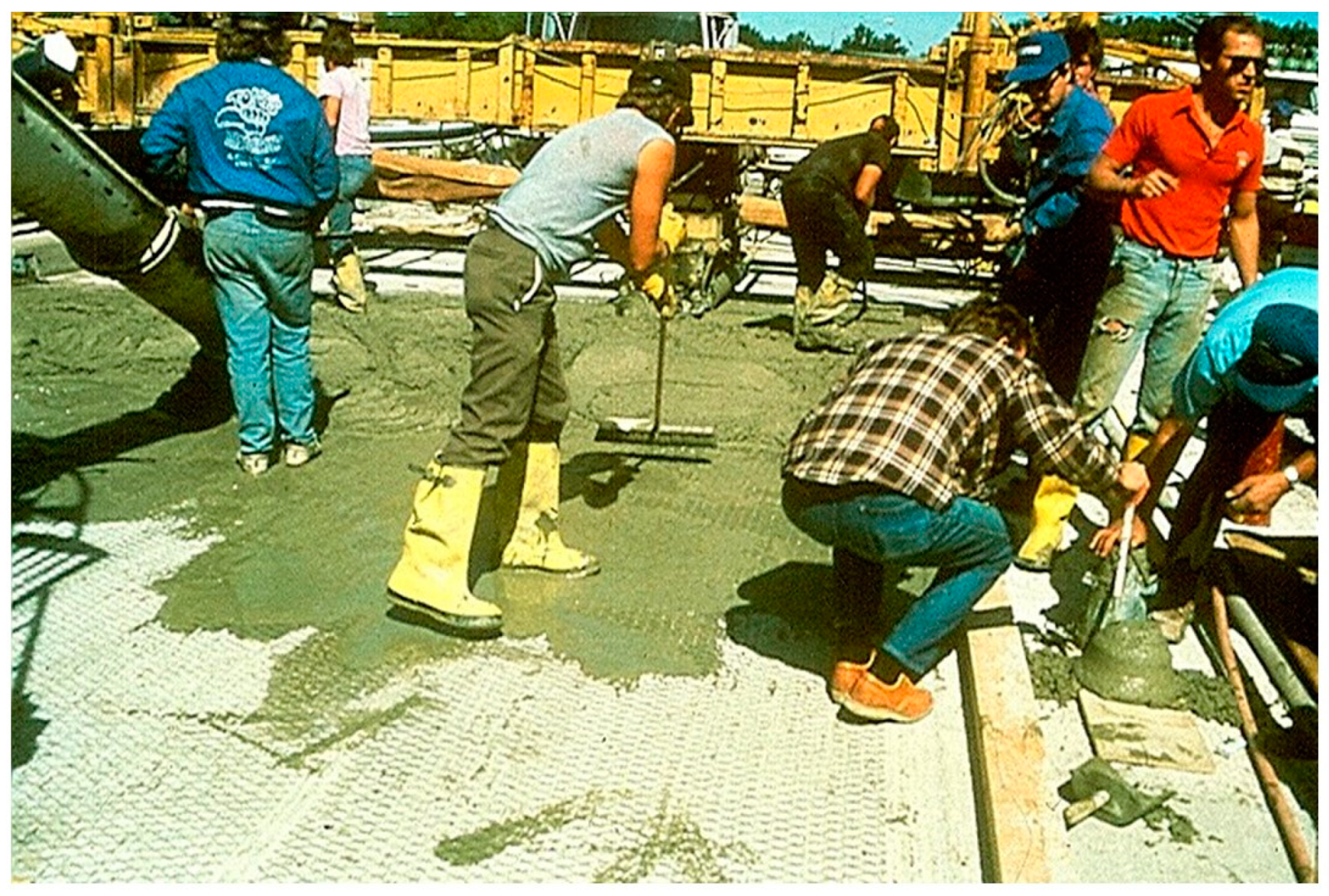
One of the first commercially developed anodes was expanded titanium mesh with a mixed metal oxide coating (MMOTi) that preferentially evolved oxygen rather than chlorine [30]. An early installation is shown in Figure 3. This proved extremely durable as an anode on bridge decks [31] but suffered from problems when applied with sprayed concrete overlays to soffits or vertical surfaces where debonding could occur [32].
Another early commercially developed anode was a copper wire in a conductive polymer cable [33]. This could be woven across a deck with a concrete overlay applied or fixed to a vertical or soffit surface and a sprayed concrete overlay applied. Unfortunately, as well as the risk of debonding of the overlay, the polymer cable proved to degrade too rapidly when used at an anode, probably for the reasons described above for carbonaceous anodes, and is no longer used in concrete [34,35].
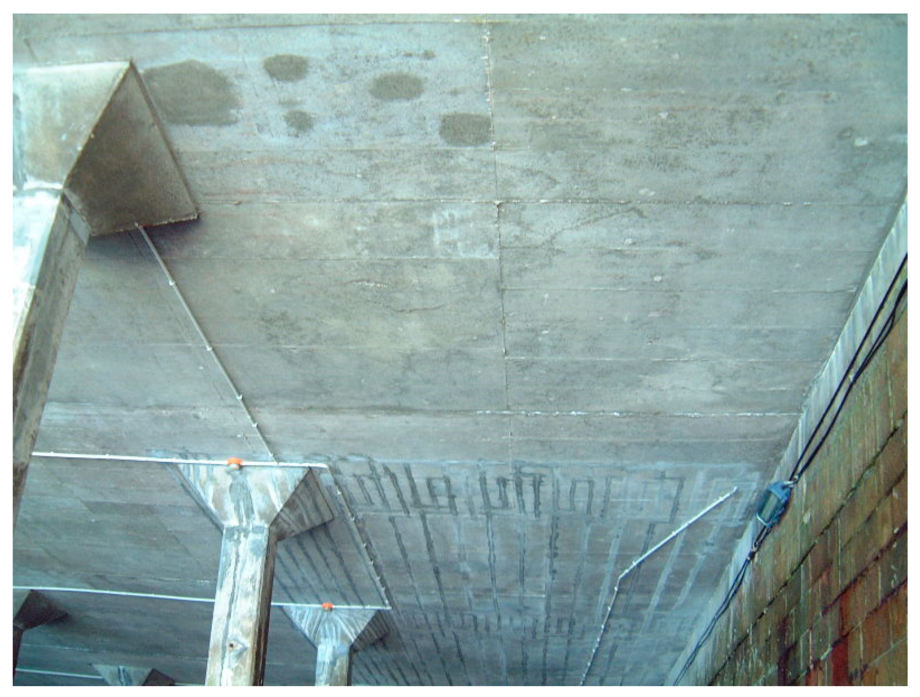
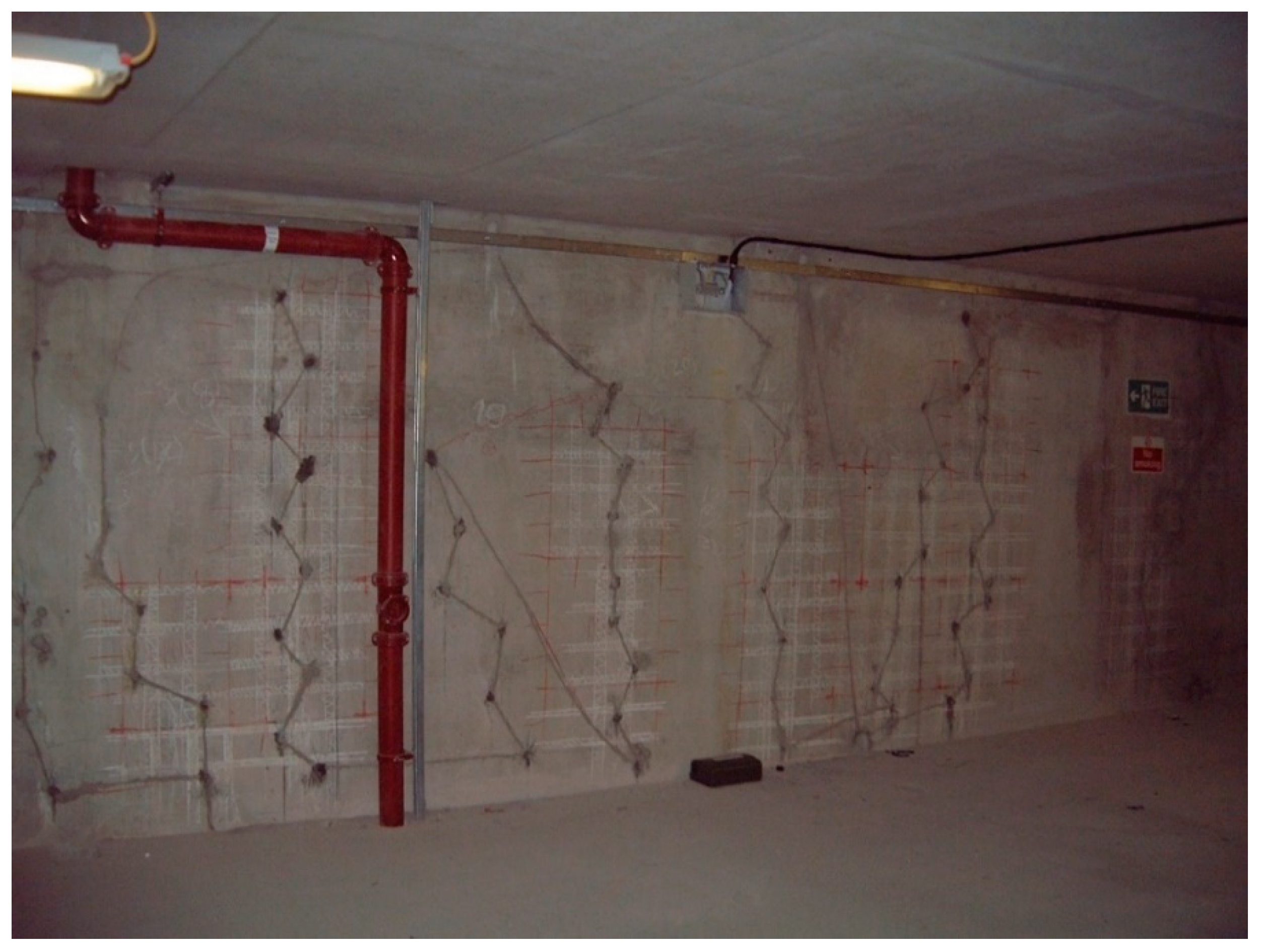
Many currently applied anode systems are MMOTi. These anodes were developed for use in the chloralkaline process, producing chlorine gas and sodium hydroxide from electrolysis of salt water and running at hundreds of amps per square metre, and they were easily adapted for the use at the maximum current density of 110 mA/m2 needed for reinforcing steel in concrete. The highly corrosion-resistant mixed metal oxide coatings were modified from the requirement to evolve chlorine gas in a chloralkali cell to the preferential evolution of oxygen. The anodes were formed into expanded mesh under overlays [36], ribbon in slots cut into the concrete cover as shown in see Figure 4, or probes, rods or tubes to be grouted into drilled holes in the concrete. An example of probe anodes drilled into concrete is shown in Figure 5 where a basement wall suffered from localised chloride ingress at cracks. As the chloride was localised around the cracks, anodes were “stitched” either side of the cracks to provide protection to the steel at risk of corrosion.
Specialised proprietary sprayed concrete overlays to improve the bond between overlay and parent concrete have been developed. Acid-resistant grouts for drilling in discrete anodes have also been developed to reduce acid attack at the steel/concrete interface. A well-documented example is the work on the development of a grout for the conductive ceramic titanium oxide tube discrete anode [37,38]. This proprietary anode is made from the other material widely used as an ICCP anode in tube form drilled into the concrete. A case history of its application on a bridge substructure is given in by Drewett and Bott [39].
The use of thermal spayed zinc as an impressed current anode for reinforced concrete was first developed in the early 1980s by Caltrans [40]. This had the advantage of not requiring an overlay, not adding to dead load or requiring drilling or slots cut. It was also more resistant to moisture than the alternative conductive paint coatings when applied to vertical and soffit surfaces. Its disadvantage is the complexity of the thermal arc spray process compared to the ease of painting concrete. The lack of commercial support has led to its limited application compared to the commercially developed aluminium–zinc–indium alloy widely used as a galvanic anode [41] and occasionally as ICCP anode.
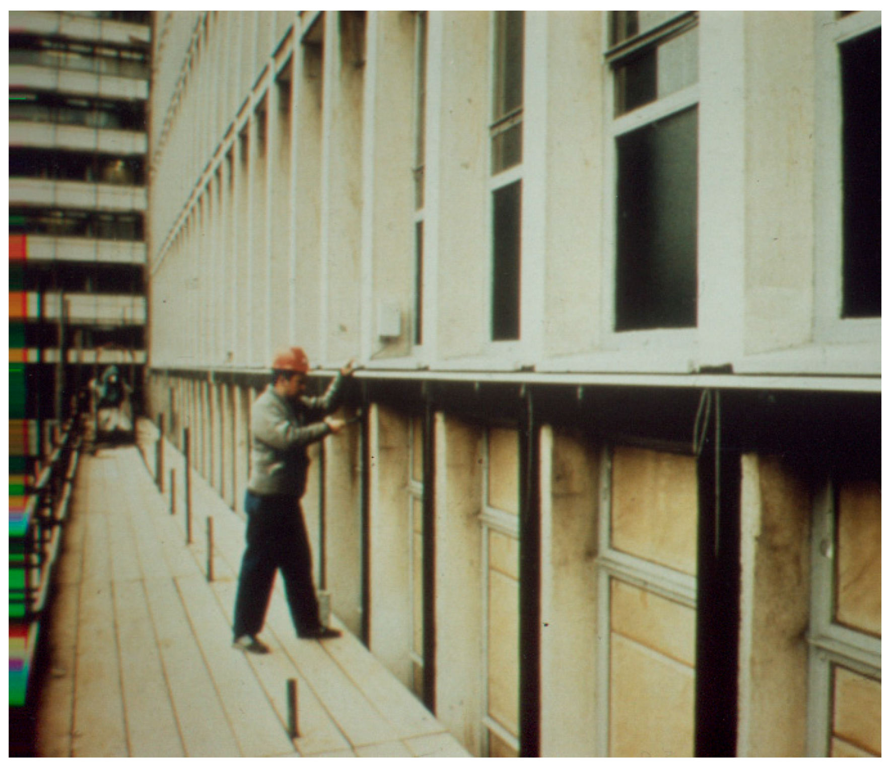
Conductive coatings with flaked graphite pigment or filler and an organic binder were developed in the USA, Canada and the UK. They were originally developed for bridge substructures [42,43] and were also applied to buildings [17] and car park soffits [44]. An early example is shown in Figure 6.
Several hundred cross head beams had conductive coating anodes applied to deal with de-icing salt leakage through the expansion joints on the elevated motorway sections around Birmingham, UK, with 740 cross heads protected by 2013 [17,45]. An alternative formulation used a conductive binder and has been employed extensively in Scandinavia, particularly in multi-storey car parks [46]. The chief advantage of these products was lack of dead weight, simplicity of application and comparatively low cost. The disadvantage was limited life, especially when exposed to water runoff. A spray applied conductive mortar with far better durability was also developed [47] and successfully applied to a jetty soffit [48] among many other projects [49]. This product uses nickel-coated carbon fibres rather than flaked graphite as the conductor.
A description of impressed current anode types, their relative advantages, limitations, applications life and cost is given in Broomfield [1] and updated in Corrosion Prevention Association Technical Note 11 [50] and Note 12, which provides UK highway bridge costing guidance for different anode types [51].

5. Development of Control and Monitoring Parameters

Due to the very low current demand of steel in concrete compared to pipeline or marine applications, the power supplies required for ICCP of steel in concrete bear little resemblance to the high current output transformer rectifiers required for ICCP of buried and submerged structures such as pipelines. Also, many early trials and installations in many countries were in relatively benign, protective environments, with the control systems located inside buildings or in small roadside cabinets in urban locations, often with easy access to telecommunications. Air cooling was generally sufficient and electronic control and remote monitoring were easily implemented. This meant that remote monitoring and adjustment with continuous logging became the standard approach. A review of the development and current designs of power supplies and monitoring systems is given by Chess and Broomfield [52].
A recent review of the control criteria for ICCP of steel in atmospherically exposed concrete has been published [53] and will not be repeated here. The 100 mV depolarisation criterion became the standard control criterion for atmospherically exposed reinforced concrete under most conditions although alternative criteria are given in ISO 12696. The 100 mV criterion is easily implemented with microprocessor controlled systems and had the great advantage that it does not require the use of calibrated embedded reference electrodes, as long as they are stable for the duration of the depolarisation measurement. Other simpler sensors were investigated such as the null probe [54]. This used a piece of reinforcing steel embedded in a chloride rich mortar, connected to the main steel via an ammeter. Before an ICCP system is switched on, it should be actively corroding, with current flowing from the anodic null probe to the relatively cathodic reinforcing cage. As the applied CP current increases, the current should decrease and then reverse. The applied CP current at reversal of current flow between probe and reinforcing cage from should show that the reinforcing cage is protected from corrosion as is the required applied ICCP current for protection. One reason for the development of the null probe and similar sensors was due to early unreliability of reference electrodes, especially when installed in bridge decks subject to heavy traffic loads and vibration [26].
However, the durability problems of “true” reference electrodes were largely overcome with the development of double junction silver/silver chloride and other reference electrodes for embedding in concrete. The major problem for the reference electrode is its limited life compared with MMOTi anodes and loss of connection to the concrete due to shrinkage of the mortar used to embed the reference electrode. Pseudo-reference electrodes such as coupons of graphite [55] and now more widely used mixed metal oxide-coated titanium coupon electrodes are also used, usually in conjunction with “true” reference electrodes. These are especially useful in systems with long design lives where the limited life of a “true” reference electrode could lead to expensive access and replacement costs. Also, loss of electrical contact is less likely than with a true reference electrode because of the larger contact area. If the 100 mV depolarisation control criterion is used then the reference electrode only needs to be stable over the period of measurement, which is usually feasible for a MMOTi or graphite electrode. There is an American National Association of Corrosion Engineers (NACE) state-of-the-art review of characteristics and embedment methods for reference electrodes commonly embedded in concrete [56]. Chess and Broomfield [52] describe probes and monitoring in chapter 11.
There has been much discussion in the industry about cables suitable for connection to anodes, reinforcement and reference electrodes. The current understanding is summarised in the Concrete Society Technical Report 73. “Cables with insulation or sheaths of polyvinyl chloride (PVC), ethylene propylene rubber (EPR) or chloro-sulfonated polyethylene (CSP) or other rubbers are unlikely to be suitable for long-term use in pH 2 to pH 13. Cables with insulation and sheaths of cross linked polyethylene (XLPE) are likely to be suitable for long-term use. Insulation of very chemically resistant materials such as Kynar may be considered, but these have disadvantages of cost, a tendency to crack at low temperatures, and they require particular care with respect to large minimum bend radii” [57]. If anodes are designed to last 40 to 100 years then it is important that other components can also last many decades before needing replacement.
Where copper cables are connected to steel or to anode within the concrete it is important that the connection method does not leave any dissimilar metals exposed. This requires encapsulation with insulation resin to protect them from corrosion [57]. One popular method often used is to heat shrink sleeving which incorporates a resin fill.

6. Design, Anode and Cathode Current Densities

The basic design requirement of any cathodic protection system is to determine the amount of current required to achieve protection. This is the surface area of steel to be protected multiplied by a design current per unit area. The measurement of the steel area requires measurement of steel bar diameters and lengths, overlap, and a determination of the extent to which the layers of steel at different depth require protection or will drain current.
Pedeferri presented one of the earliest investigations into the principles of cathodic protection of steel in concrete and the current density required for protection [58]. The various protective effects induced by the cathodic polarisation, the differences between the cathodic protection applied for controlling the corrosion rate of chloride contaminated structures and to protect new structures expected to become contaminated were discussed. He also looked at applying ICCP to steel corroding in carbonated concrete and the protection conditions which avoid the risk of hydrogen embrittlement in prestressed structures.
The European and subsequent standard EN ISO 12696 [59] give recommendations in an informative annexe on the design current density ranges to protect steel in concrete. These are given as 2 to 20 mA/m2 for steel in chloride-contaminated concrete and 0.2 to 2 mA/m2 for steel in concrete not (yet) chloride-contaminated. A case study of calculation of current densities and the resultant field performance on a bridge substructure using the above current density ranges was published by Broomfield [60]. This subject was also looked at mathematically by Hussainein et al. [61].
Bartholomew et al. [62] and Glass and Buenfeld [63] looked in detail at the current per unit steel area (current density) required to protect steel in concrete. Bartholomew et al. carried out laboratory trials to correlate the current density, amount of polarisation required to achieve a corrosion rate of less than 25 μm/y at different chloride levels. However, the work was done in dampened sand rather than in concrete. Glass and Buenfeld calculated the current required to keep chlorides way from the steel and published theoretical curves relating current density, potential shift and corrosion rate.
Many ICCP systems are overdesigned in terms of the design current required. There are very few cases of systems being under designed in terms of anode or power supply capacity. It is always safer to overdesign than to under design, and anode life can be considerably extended when the maximum applied current density is significantly lower than the design limit. However, this means that too much anode may be used and power supplies are overrated and can, therefore, be less efficient.
There has been much discussion of maximum anode current densities. Early work found that a current density of 10 mA/ft (approximately 100 mA/m2) of active anode surface minimised the acidification of the anode/concrete interface. Much of this work was based on carbon based anodes such as the early FHWA grout in slot system and the conductive cable in concrete overlay. This was adopted by manufacturers of the MMOTi mesh and ribbon anodes. However, when the probe or discrete anode systems were developed there was a strong incentive to make these as cost effective as possible by maximising the anode/concrete interface current density to minimise the amount of holes drilled and the number of anodes used. Detailed and long-term testing showed that anodes in suitable mortar back fills could run at much higher current densities, up to 900 mA/m2 [37,38]. However, the standards still stipulate a long-term design current density of 100 mA/m2.
Anode spacing for ribbon and probe anodes is generally prescribed in manufacturer’s literature based on the steel density and design current densities of anode and steel. The early designs of anodes in slots had a 1 ft (300 mm) spacing [27], and generally designers stick to a 300 to 450 mm spacing to ensure even current distribution. Small scale trials prior to a full installation [52] are also used to optimise anode spacing.
When considering the surface area of steel to be protected, it is usual practice to divide the part of the structure being protected into zones. While the earlier systems covered a whole bridge deck in a single zone, as more complex structures were protected, dividing the structure into zones became the preferred method of design once it had been shown that there was minimal interaction between zones and outside zones for atmospherically exposed zones [18]. Zone sizes are determined by a number of factors:
  • Overall size for even current spread and controllability; experience has shown that anode zones of 50 to 100 m2 of concrete surface area are usually suitable, as discussed in Chess and Broomfield [52]. However, much smaller zones are used on some structures, and much larger zone can also be suitable, e.g., bridge or multistorey car park decks or soffits.
  • Direct current (DC) output levels of the power supply; these are typically 1 or 10 amps, therefore limiting the zone to 50 m2 of steel at a design current density of 20 mA/m2 for a 1 amp unit or at the other extreme 1000 m2 at 10 mA/m2 for a 10 amp unit.
  • Variations in steel density; the soffit of a beam may have far more steel than the sides so the soffit may be one zone and the sides another.
  • Exposure conditions, the most extreme being piers in marine situations where there can be fully immersed tidal and splash zones which may require different anodes and even different control criteria [64].
There is also the issue of the current density required for cathodic prevention systems applied to new structures or those with negligible levels of chloride or carbonation [65]. The ISO standard advises that current densities of 0.2 to 2 mA/m2 but higher levels have been reported [66].

7. The Development of Guidance Documents and Standards

It was reported that 287 ICCP systems had been installed on US bridge decks by 1989 [10] and the first standards were the American National Association of Corrosion Engineers recommended practice NACE RP0290 and the European standard BS EN 12696, both published in 1990. A little after that the American Association of State Highway Transportation Officials (AASHTO) published the first national specification for ICCP of bridge decks [67], nearly a decade after Ontario had published its Bridge Deck Rehabilitation Manual, which included specifications for ICCP of bridge decks [25]. The SHRP programme also published a manual of practice [68]. A guidance document on ICCP of reinforced concrete was published by the UK Concrete Society in collaboration with the Institute of Corrosion and NACE. This was published a year before the standards, in 1989 [69], and was the basis for the European standard. The Concrete Society also published a model specification [70]. These have now been combined and updated to incorporate galvanic cathodic protection for steel in concrete and cover buried and submerged systems [57]. The UK Highways Agency published a guidance document on ICCP of highway structures, recently revised [71]. This now covers ICCP and galvanic anode systems for highway structures and includes appendices giving a comparison of the two systems and the merits of applying CP. The UK Highways Agency also has a draft specification for CP of reinforced concrete highway structures in final preparation as part of its manual of contract documents for highway works but unpublished as yet.
The European standard was updated to include galvanic CP and buried and submerged concrete structures and has been adopted as an ISO standard [59]. It is presently being revised for ISO by the CEN committee that drafted the original document. The current NACE standard practice is more concise, and only covers ICCP of atmospherically exposed reinforced concrete [72]. There is a separate NACE standard on the application of CP to buried and submerged reinforced concrete [73] and another on galvanic CP [74]. NACE has also published a report on the evaluation of the effect of CP on steel in concrete, particularly where the control criteria in the standards are not met [75]. A comparison of the available standards was published by Broomfield in 2006 [76] and in chapter 7 of Broomfield [1]. Although both analyses are of earlier issues of the documents, the changes have not been substantial. An Australian standard has also been published [77]. In the middle east the Saudi Arabia Basic Industries Corporation (SABIC) has also published an engineering standard [78] primarily aimed at structures containing seawater, i.e., intake/discharge ponds and/or basins, cooling towers, pump sumps, canals, basins and sumps due to the high ambient chloride levels. The standard covers application of ICCP installed during construction, often referred to as cathodic prevention, as well as retrofitting existing structures after reinforcement corrosion has initiated.
NACE International has had formal training courses on cathodic protection for many years. These were primarily aimed at pipeline, oil and gas and marine applications, but increasingly cover concrete applications. When the European Standards Organisation CEN, decided to set up a training and certification system for cathodic protection engineers and operatives, it decided to set up separate modules for the different application areas [79] Therefore, it specifically trains operatives in ICCP in steel in concrete. This standard was revised and has been adopted by ISO [80]. Courses meeting the ISO standard are run by national corrosion societies in several European countries. NACE runs its CP training certificated courses throughout the Americas and many other countries, particularly in the Middle and Far East.
Test methods for ICCP anodes were developed, originally by NACE. The one for embedded mixed metal oxide-coated titanium anodes was originally a type certification procedure for the desired design life of the anode. The latest revision includes a quality assurance batch test to be conducted on samples taken from anodes either prior to dispatch from the supplier or collected from the site [81]. These standard test methods were adopted, with text format changes, by ISO [82].
NACE also developed a test method for conductive coatings [83]. This is more problematic than testing MMOTi as it is not possible to accelerate testing on anode coatings on concrete due to acid formation at the concrete/anode interface, which is usually critical to the durability and performance and the anode. The test should be considered to demonstrate that a coating system that fails the test is not suitable as a coating anode. However, only extended field trials will demonstrate the performance and durability of a conductive coating anode in practical applications.
There is also a specification for applying thermal sprayed zinc to steel developed by the American Welding Society [84].
There is little guidance in the standards on the suitability of ICCP in comparison with other concrete repair options. NACE Standard Practice 390 is the only standardised guidance on how to assess the corrosion condition of a reinforced concrete structure with guidance on treatment options and maintenance requirements [85]. The European standards for concrete repair include a part on principles of repair [86]. This lists ICCP as suitable for treating reinforcement corrosion, especially once corrosion has started referencing BS EN 12696, now ISO 12696.
In the technical literature, American Concrete Institute report 222 [87] discusses ICCP along with other treatment options and reports their limitations. However, the references regarding ICCP are quite old along with the descriptions of the outdated coke asphalt and silicon iron anode system. Broomfield [1] includes a table, listing pros and cons of different repair options including barriers, patching, ICCP, galvanic CP, electrochemical chloride extraction and realkalization. There is also an online model for assessment of structures and selecting and relative costing of treatment options including conventional and electrochemical treatments [88]. While these standards and guidance documents can be useful, a suitably qualified and experienced specialist or team should investigate the problem and select the optimal treatment based on the condition, prognosis and service requirements of the structure.

8. Issues with the Application of Impressed Current Cathodic Protection (ICCP)

For an ICCP system for atmospherically exposed reinforced concrete to perform correctly, a number of parameters must be satisfied.
  • The anode must bond to the concrete and current must flow evenly from anode to steel at a sufficiently low resistance.
  • There must be no electrical short circuits between anode and steel.
  • The reinforcement and all other embedded metal must be electrically connected together. (continuity and stray current).
  • There must be no adverse reactions in the concrete such as alkali aggregate reaction or significant loss of bond between steel and concrete.
  • The variations in resistivity of new and previous repair patches must allow current to pass evenly to the steel in order to achieve protection.
The issue of anode to concrete bond had been discussed above in the context of anode maximum design current density. The acids generated by the anodic reactions can degrade the cement paste. Carbon-based anodes are most susceptible to this due to the generation of CO2 which carbonates the concrete. Loss of bond of anode to concrete and increasing circuit resistance frequently occur as carbonaceous anode systems age as discussed above.
The issue of electrical short circuits has occurred on a number of projects, either due to lack of cover or tie wires directly shorting the anode to the steel, although these are rarely reported in the open literature. This issue is more significant on some anode types. Thermal sprayed zinc is highly conductive and a short circuit will disable an entire zone. One solution is to attach a resistance meter between anode and reinforcement during the spraying process so that short circuits can be identified promptly. The problem is also significant when MMOTi ribbon anodes are used for cathodic prevention systems, applied to new construction where anode ribbons are attached via isolating spacers to the reinforcing cage [89]. In this case also a resistance meter between anode and steel during the construction process can give warnings of short circuits. However, while it is relatively easy to stop a thermal spray process and identify a short circuit, the author has found that it is far harder to stop a concrete pour during construction to identify and rectify a short circuited ribbon anode. Also, a large zone with wet concrete between anode and reinforcement does not have a very high electrical resistance, so identifying the change in resistance due to a short circuit between them can be difficult.
The continuity of the steel reinforcing bars and any other embedded steel within the zone is important. If any steel is not connected to the negative terminal of the DC power supply, current will flow from the anode to one part of the steel, cathodically protecting it, but then must flow out of the isolated steel to the steel continuous with the power supply. This location will be an anode and corrosion will occur. This is known as stray current and its detection and mitigation from ICCP systems and other sources are given in a NACE report [90] and a Standard Practice [91].
While most reinforcement cages are sufficiently electrically continuous from the cage fabrication process, problems occasionally arise with badly corroded steel especially if elements are lightly reinforced and also on structures with multiple separate reinforcing cages. An early example of the need to bond reinforcement together for the application of ICCP is given in the description of the ICCP system applied to the substructures of four wharves at Mina Zayed, Abu Dhabi [92]. The test for discontinuity of embedded steel from the main cage for ICCP is based on work done by Bennett [93] which has never been formally reported or duplicated but is the basis for the requirements in the standards. It was also for ICCP although it is applied to galvanic systems which, with lower driving voltage, may need higher conductivity between reinforcing bars. It was found that there was adequate continuity with a resistance of 1 ohm or less measured between two embedded pieces of steel, and the same reading with leads reversed. A simple multimeter is frequently used as it uses a very small current making it most sensitive to small separations by thin layers of corrosion products rather than metal to metal contact. An alternative is to measure the potential difference between the two pieces of steel and a static reference electrode with a high impedance (>500 Mohm) voltmeter. The readings should not differ by more than 10 mV.
The issue of the effect of the alkali silica reaction (ASR) was raised due to the increase in alkali content at the reinforcement due to the cathodic reaction [94]. There was a concern that concretes containing aggregates with marginal susceptibility to ASR would react. However, the application of ICCP to a number of structures with marginal or more serious levels of ASR susceptibility has shown no adverse effects. The ISO standard 12696 [59] Annex 6 states that cathodic protection applied in accordance with the standard has been demonstrated to have no influence on the alkali silica reaction.
A wider issue of the effect of CP current on reinforcement pull out strength has also been raised. Early laboratory tests identified potential problems suggesting that bar pull out strength may be reduced by about 20% in those bridge decks subjected to CP current levels. This reduction was ascribed to the accumulation of migrating sodium and potassium ions leading to softening of the concrete around bars under the influence of applied CP currents while earlier studies suggested 10% reduction. Hydrogen evolution was also suspected of reducing bond strength. However, many early tests were conducted at unrealistically high current densities [95]. An analysis in the SHRP program found no problems see SHRP-S-337 [96]. No problems were found in tests and samples of bars taken from the field [97]. Neither were there issues found in tests of concrete subject to electrochemical chloride extraction where the current density is typically 100 times that of ICCP (1 amp/m2 compared to 10 mA/m2 for ICCP) [98].
Since monatomic hydrogen can be evolved at the cathode (steel) at potentials more negative than the hydrogen evolution potential it is important to define the hydrogen evolution potential and any steel in a structure that might be susceptible to hydrogen embrittlement. There is also the issue that notched specimens were had a higher susceptibility to brittle failure than smooth specimens. While the NACE and ISO standards agree that all steel potentials should be more positive than −1100 mV vs. copper/copper sulfate or −1000 mV vs. Ag/AgCl/0.5 M KCl reference electrode to minimise hydrogen evolution on all steels, more positive limits are required in the presence of steel susceptible to hydrogen embrittlement. NACE produced a state-of-the-art report on the criteria for CP of prestressed concrete structures [99] based on extensive work by Hartt et al. [100]. This suggests qualification criteria for applying CP based on steel condition, stress and susceptibility, with suggested test regimes, including on strands extracted from post-tensioned structures to be treated with ICCP. ISO 12696 states that although the recommended limit is −900 mV vs. (Ag/AgCl/0.5 M KCl electrode), hydrogen can be evolved at more positive potentials particularly if the steel is corroded (i.e., with notches in it).
Pedeferri and colleagues pioneered the application of ICCP to bridge decks with post-tensioning, in mountain regions of North Italy, using a self-limiting control system to achieve the criteria he developed [101]. This approach has not been used elsewhere.
In practice, if CP of high-strength steel is essential or unavoidable, the preferred method for protecting steel susceptible to hydrogen embrittlement is to use galvanic anodes, preferably zinc-based. These are very unlikely to polarise the steel beyond the hydrogen evolution potential. However, the potentials and the steel condition should be monitored carefully and the NACE qualification criteria [99] applied.
It has been a major issue in practice on some projects to identify steels that might be susceptible to hydrogen embrittlement when subject to CP. The most common situation is where ICCP is applied to normal strength steel but there is post tensioning nearby. The author has been involved in a trial where post-tensioned beams were connected to conventionally reinforced-concrete bridge cross heads subjected to ICCP. Monitoring showed no significant shift in potentials of the steel. In another case the reinforcement in a hollow box girder bridge was subject to galvanic CP with the post-tensioned anchorages monitored for potential shifts. No significant or detrimental shift in potential was measured. In a third case a sea wall was subject to galvanic CP. The high-strength steel anchorages were initially found to be at risk of hydrogen embrittlement. However, more refined testing at the potentials observed in the galvanic system found no susceptibility to embrittlement.
There has been much discussion by cathodic protection design engineers about the resistivity of concrete used in repairs with ICCP systems for reinforced concrete structures. It has long been the consensus that epoxy mortars and mortars containing conductive fibres are incompatible with ICCP. The statements in the European and ISO standards have changed with each edition. Broomfield [102] summarised the problems of measuring resistivity in the field and stated that the laboratory-tested resistivity, vacuum saturated and tested in compliance with RILEM TC-154 [103], should generally not exceed 150 kohm.cm or should be within 50% to 200% of the resistivity of the parent concrete measured, as far as possible in a comparable manner.

9. International Expansion and Case Histories

In the first section we discussed how the initial development of ICCP for atmospherically exposed reinforced-concrete structures was in the USA, due to the use of “bare” concrete bridge decks. While there was a rapid initial expansion in its use from 1973 to the early 1990s [10], it then started to lose popularity as state highway agencies discovered that they did not have the capacity to maintain the systems. This was summarised in a US National Cooperative Highway Synthesis Report in 2004 [104]. This stated that cathodic protection systems have been used; however, they have not proven to be maintenance-free or cost-effective. The issue of the ability of US bridge owners to maintain ICCP systems had been raised in an earlier SHRP report [24]. Alternative options such as overlays, deck sealers, partial depth and full deck removal were found to require lower maintenance. Fewer systems were applied to standard bridge decks in North America but more were applied to substructures and to non-standard bridges where the durability of other options was more limited. These systems were found to be more cost effective [105].
Examples of large-scale applications to US highway bridges include the substructures of historic bridges on the Oregon coast [106,107], where the substructures had thermal sprayed zinc applied to many thousands of square metres of concrete, see Figure 7. These were also studied for their long-term performance as an anode [108].
Figure 7 shows a leaf pier in the central reservation of a motorway in the UK with thermal-sprayed zinc applied to the main surface and probe anodes installed at the ends and under the bearing shelf where there were higher moisture levels [109].
In Missouri, a series of post-tensioned box girder bridges where the reinforced deck (away from the post tensioning ducts) was suffering from reinforcement corrosion and had ICCP applied [110]. The Florida State Department of Transportation (FDOT) found significant problems with its highly corrosive coastal areas and the bridges substructures. FDOT has installed large numbers of ICCP and galvanic anode systems to the substructures of coastal bridges [111].
The Ontario Ministry of Transportation installed large numbers of ICCP systems on bridge decks and substructures, refining the early silicon iron and conductive asphalt system before moving on to a wider variety of anodes. Like many highway agencies, they found the regular maintenance of large number of ICCP systems of different types and control systems hard to sustain [27].
North American usage of ICCP has expanded beyond highway structures. A recent example is its application to reinforced concrete water infrastructure using expanded titanium mesh anodes on a reservoir outlet tower [112].
In Europe, the Netherlands have installed a number of highway systems and kept track of their performance [113]. They reported on 150 structures protected with ICCP. Degradation of components and systems appears to have occurred in a limited number of systems. On average, the time until minor repair of parts was necessary was about 15 years. There was a follow up report in 2014 [114] in which they found that of the 150 structures with ICCP applied covering 85,000 m2 over 25 years, only 2 had been removed. They found limited durability problems, mainly around poorly detailed connections and primary anodes, frequently due to the corrosion of copper in both cases. An earlier report from Switzerland described systems applied to tunnel walls as well as bridges [115]. In Italy, Pedeferri and colleagues pioneered the application of ICCP to bridge decks with post-tensioning [101].
In the UK, a wide variety of structures were being protected with ICCP from the earliest applications including buildings and marine structures [18,116]. On the motorway system, over 700 cross heads supporting motorway bridge decks had ICCP applied by 2012 [45], initially with conductive coating anodes, along with improvements in drainage to extend the life of the anodes.
In the Middle East, the prevalence of salt in the soil, air, water and cast into concrete means that up to 74% of reinforced concrete structures showed significant corrosion damage after as few as 10 to 15 years [117]. This means that cathodic prevention systems are widely used on new construction including industrial plants [89]. The environment is so aggressive that there are examples where the current density required on the steel can be significantly higher than that recommended in the standards. Callon et al. [118] found that although ISO 12696 recommends cathodic prevention design current densities of 0.2 to 2 mA/m2, the current density on newly constructed bridges on the coast of Bahrain was 5 mA/m2. Chaudhary et al. gave examples of good long-term performance of ICCP systems on seawater cooling conduits in chemical plants [119]. Callon recently gave a case history of ICCP and galvanic CP applied to 100,000 m2 of reinforced concrete in a ship repair yard [66].
An overview of the international perspective of ICCP for atmospherically exposed reinforced-concrete structures is given in Corrosion Prevention Association Technical Note 3 [120]. This estimates the number of square metres of anode that has been applied in different parts of the world and the range of structures, including the Carillon Tower of the National War Memorial in New Zealand [121], the walkway supports of the Sydney Opera House [122], cooling towers and other industrial plant in the Middle East [78,123].

10. Concluding Remarks

It has been estimated that around 50% of construction industry spend in the UK is on repair and refurbishment, see Matthews and Morlidge [124]. As the built infrastructure constructed in the construction boom of the 1970s approaches the end of its functional life, or at least reaches the point where major repair and maintenance is essential to keep it functioning, this ratio may increase. Reinforcement corrosion is a major cause of the deterioration of reinforced concrete structures. In a review of concrete repair work it was found that only 50% of repairs were classed as being wholly satisfactory when last inspected and 60% failed in the first 10 years. The common causes of failure were reported as being incorrect diagnosis, incorrect design of the repair, selection of unsuitable repair materials, and poor workmanship, according to research by Tilly [125]. The development of improved standards and training means that we can hope that the repairs and treatment we carry out now are an improvement on those of the past.
While the standards and guidance documents described here can be useful, a suitably qualified and experienced specialist or team should investigate the cause and extent of deterioration in any reinforced-concrete structure and select the optimal treatment based on the condition, prognosis and service requirements of that structure.
ICCP is the only treatment for chloride-induced corrosion that can control reinforcement corrosion successfully over many decades. The systems need to be installed with a correct diagnosis of the cause of deterioration. They must be appropriately designed, including the most appropriate anode system. They must be designed and installed by appropriately qualified personnel and then correctly operated and maintained. All of this is as required in the international standards [59]. While anodes can last 40 to 100 years, other components can be less durable. The electronics probably have the shortest life but are by far the easiest element to replace. Reference electrodes have limited lives but can be supplemented with graphite or MMOTi probes.
There is a range of other electrochemical corrosion control treatments, one of the more recent developments being a hybrid anode system comprising a galvanic anode which receives an initial electrical charge [126,127,128]. It has the advantage over ICCP of not requiring a permanent power supply. However, it requires the separation of anodes from steel, cabling, monitoring and maintenance to check that protection is achieved and maintained.
ICCP is not the easiest treatment to apply or maintain. However, any reinforced-concrete structure suffering from significant chloride-induced corrosion will require ongoing maintenance and repair whatever treatment option is selected. If a service life beyond 20 years or so is required and if the access costs are significant, then ICCP is likely to be a competitive option. The particular requirements and expertise required of an ICCP system, however, means that for some clients it is not suitable for their business models. This may be part of the reason that it is no longer widely used on North American bridge decks, along with the fact that newer bridge decks contain fusion-bonded epoxy coated rebar which are more corrosion-resistant in many circumstances.
While ICCP is rarely used any more on the reinforced concrete bridge decks for which the technology discussed here was originally developed, it has found a useful place in the preservation and life extension of bridge substructures, buildings and a wide range of reinforced-concrete structures exposed to sea salt, deicing salts and other sources of chloride ions.
Further refinements of the anode system and materials and of the control equipment may make ICCP more flexible as regards where and how it is applied. However, attempts to further automate control and monitoring systems should be viewed with caution. The improvement in training of ICCP designers, installers and operators to international standards means that the condition of the structure can be fully understood by an appropriately trained and experienced engineer and appropriate action taken to ensure that protected structures remain at low risk despite the aggressive environment, rather than relying on artificial intelligence or other automated systems. For clients requiring simpler maintenance regimes than those offered by ICCP, there are the alternatives of conventional repair, galvanic cathodic protection and other electrochemical techniques as discussed elsewhere, e.g., Broomfield [1] or NACE Standard Practice 0390 [85].

Funding

This research received no external funding.

Acknowledgments

The author would like to acknowledge the following who supplied papers and other information referenced in this study; Gareth Glass of CP Technology, Ulrich Schneck of Citech, Bernd Isecke of Corr-Less Consulting, Brian Wyatt of Corrosion Control, Jim Preston of Corrosion Prevention Ltd. Richard Palmer of Palmer Consulting and Xavier Hallopeau of Freyssinet, and Jack Bennett for permission to publish Figure 2 and Figure 3.

Conflicts of Interest

The author declares no conflict of interest.

References

  1. Broomfield, J.P. Corrosion of Steel in Concrete-Understanding, Investigation and Repair, 2nd ed.; Taylor and Francis: London, UK, 2007. [Google Scholar]
  2. Davy, H. On the corrosion of copper sheeting by seawater, and on methods of preventing this effect, and on their application to ships of war and other ships. Phil. Trans. 1824, 114, 151–246. [Google Scholar]
  3. Corrosion Doctors. Available online: https://corrosion-doctors.org/Corrosion-History/CP-History.htm (accessed on 28 July 2020).
  4. Unz, M. Cathodic protection of prestressed concrete pipe. Corrosion 1955, 11, 80. [Google Scholar] [CrossRef]
  5. Heuze, B. Cathodic protection of steel in prestressed concrete. Mater. Prot. 1965, 4, 57–62. [Google Scholar]
  6. Vrable, J.B. Cathodic Protection for Reinforced Concrete Bridge Decks; Laboratory Phase, Report 180, National Cooperative Highway Research Programme; Transportation Research Board: Washington, DC, USA, 1977. [Google Scholar]
  7. Stratfull, R.F. Progress report on inhibiting the corrosion of steel in a reinforced concrete bridge. Corrosion 1959, 15, 331t–334t. [Google Scholar] [CrossRef]
  8. Stratfull, R.F. Experimental cathodic protection of a bridge deck. Transp. Res. Rec. 1974, 500, 1–15. [Google Scholar]
  9. Stratfull, R.F. Eleven years of success for coke breeze c.p. pavement. In Proceedings of the NACE Conference on Cathodic Protection of Reinforced Concrete Bridge Decks, San Antonio, TX, USA, 12 February 1985; pp. 66–81. [Google Scholar]
  10. Broomfield, J.P. Field survey of cathodic protection on North American bridges. Mater. Perform. 1992, 31, 28–33. [Google Scholar]
  11. Perenchio, W.F.; Landgren, J.R.; West, R.E.; Clear, K.C. Cathodic Protection of Concrete Bridge Substructures. In TRB National Cooperative Highway Research Program Report 278; Transportation Research Board: Washington, DC, USA, 1985. [Google Scholar]
  12. OECD. Durability of Concrete Road Bridges; Organisation for Economic Cooperation and Development: Paris, France, 1989. [Google Scholar]
  13. Page, C.L.; Treadaway, K.W.J. Aspects of the electrochemistry of steel in concrete. Nature 1982, 297, 109–115. [Google Scholar] [CrossRef]
  14. Broomfield, J.P. Physical and chemical repair and rehabilitation techniques. In Corrosion of Steel in Concrete, 2nd ed.; Taylor and Francis: London, UK, 2007; pp. 112–139. [Google Scholar]
  15. Sergi, G.; Seneviratne, A.M.G.; Maleki, M.T.; Sadegzadeh, M.; Page, C.L. Control of reinforcement corrosion by surface treatment of concrete. Proc. Instn. Civ. Engrs. Struct. Build. 2000, 140, 85–100. [Google Scholar] [CrossRef]
  16. Virmani, Y.P.; Clemena, G.G. Corrosion Protection–Concrete Bridges, FHWA-RD-98-088; Federal Highway Administration: McLean, VA, USA, 1998. [Google Scholar]
  17. Wallbank, E.J. The Performance of Concrete in Bridges. In Department of Transport (UK) Report; HMSO: London, UK, 1989. [Google Scholar]
  18. Broomfield, J.P.; Langford, P.E.; McAnoy, R. Cathodic Protection for Reinforced Concrete: Its Application to Buildings and Marine Structures. In Corrosion of Metals in Concrete; NACE: San Francisco, CA, USA, 1987. [Google Scholar]
  19. Glass, G.K.; Green, W.K.; Chadwick, J.R. Long Term Performance of Cathodic Protection Systems on Reinforced Concrete Structures. In Proc. UK Corrosion 91, Manchester; Inst. Corrosion: Northampton, UK, 1991. [Google Scholar]
  20. Geoghegan, M.P.; Das, S.C.; Broomfield, J.P. Conductive Coatings in Relation–Cathodic Protection; Taylor Woodrow Construction Ltd.: Southall, UK, 1985. [Google Scholar]
  21. McKenzie, M. Cathodic protection of reinforced concrete bridges. In Proc. Protection of Concrete, Dundee; E&FN Spon: London, UK, 1990; pp. 641–651. [Google Scholar]
  22. Gower, M.; Beamish, S. Cathodic Protection on the Midland Links Viaduct. Constr. Repair 1995, 9, 10–13. [Google Scholar]
  23. Blankvoll, A. History of the GimsØystaumen Bridge Repair project. In Proc. Repair of Concrete Structures; Norwegian Road Research Laboratory: Oslo, Norway, 1997; pp. 1–7. [Google Scholar]
  24. Escola, L.; Huura, J.; Vaelitalo, S. Cathodic protection with conductive primer as anode: Practical Experiences from Hessund Bridge. In Proc. Repair of Concrete Structures; Norwegian Road Research laboratory: Oslo, Norway, 1997; pp. 349–356. [Google Scholar]
  25. Broomfield, J.P.; Tinnea, J.S. Cathodic Protection of Reinforced Concrete Bridge Components, Strategic Highway Research Program SHRP-C-92-1; Transportation Research Board: Washington, DC, USA, 1992. [Google Scholar]
  26. Manning, D.G. Ontario’s Bridge Deck Rehabilitation Manual. In Proceedings Conference of Cathodic Protection of Reinforced Concrete in Bridges and Decks; NACE: Houston, TX, USA; San Antonio, TX, USA, 1987. [Google Scholar]
  27. Schell, H.C.; Manning, D.; Pianca, F. A decade of bridge deck cathodic protection in Ontario. In NACE Symposium on Corrosion of Metals in Concrete; NACE: Houston, TX, USA, 1987; pp. 65–78. [Google Scholar]
  28. Clemena, G.G. A Slotted Cathodic Protection System for Bridge Decks. In Proceedings Conference of Cathodic Protection of Reinforced Concrete in Bridges and Decks; American Association of State Highway Officials; Federal Highways Administration and National Association of Corrosion Engineers: Washington, DC, USA, 1985; pp. 89–103. [Google Scholar]
  29. Bennett, J.E.; Clear, K.C. Cathodic Protection of Steel in Concrete: A State-of-the-Art Report SHRP-S-337; Strategic Highway Research Program; Transportation Research Boards: Washington, DC, USA, 1993. [Google Scholar]
  30. Martin, B.L.; Bennett, J.E. An Activated Titanium Mesh Anode for the Cathodic Protection of Reinforcing Steel in Concrete. In Corrosion of Metals in Concrete; NACE: Houston, TX, USA, 1987; pp. 255–259. [Google Scholar]
  31. Bennett, J.; Turk, T.; Firlotte, C.; Sexton, M. Testing old cathodic protection on Ohio Bridge Decks. Mater. Perform. 2012, 51, 31–37. [Google Scholar]
  32. Kessler, R.J.; Lasa, I.R.; Powers, R.G. Polypropylene Fiber Reinforced Concrete in Cathodic Protection Applications. In Proc. NACE Corrosion 2004; Paper 04341; NACE International: Houston, TX, USA, 2004. [Google Scholar]
  33. Kendell, K.; Pithouse, K.B. The Raychem Flexible Anode System. In Corrosion in Concrete-Practical Aspects of Control by Cathodic Protection; Paper No. 6; Global Corrosion Consultants: Telford, UK, 1987. [Google Scholar]
  34. Eastwood, B.J.; Christensen, P.A.; Armstrong, R.D.; Bates, N.R. Electrochemical oxidation of a carbon black loaded polymer electrode in aqueous electrolytes. J. Solid State Electrochem. 1999, 3, 179–186. [Google Scholar] [CrossRef]
  35. Mietz, J.; Fischer, J.; Isecke, B. Cathodic protection of steel-reinforced concrete structures–results from 15 years’ experience. Mater. Perform. 2001, 40, 22–25. [Google Scholar]
  36. Bennett, J.E. An Activated Titanium Mesh Anode for Cathodic Protection of Steel in Concrete. UK Corros. 1987, 87, 93–114. [Google Scholar]
  37. Hayfield, P.C.S.; Hill, A. Ebonex® Discrete Anodes in the Cathodic Protection of Rebar in concrete: Performance of Ebofix Grouts. Int. J. Restor. Build. Monum. 2000, 6, 655–668. [Google Scholar]
  38. Sergi, G.; Simpson, D.; Hayfield, P.C.S. Long Term Behaviour of Ceramic Tubular Shaped Anodes for Cathodic Protection Applications. In NACE Corrosion Conference Rehabilitation of Reinforced Concrete Structures by Electrochemical and Other Techniques and Corrosion Protection Strategies for Construction; Paper No. 08305; NACE International: Houston TX, USA, 2008. [Google Scholar]
  39. Drewett, J.; Bott, N. The Refurbishment of Bideford Longbridge Proc Concrete Solutions; Mechtcherine, G., Dresden, S., Eds.; CRC Press: London, UK, 2012; pp. 15–18. [Google Scholar]
  40. Apostolos, J.A. Cathodic Protection Using Metallized Zinc. Mater. Perform. 1987, 26, 22–28. [Google Scholar]
  41. Funahashi, M.; Young, W.T. Field Evaluation of a New Aluminum Alloy as a Sacrificial Anode for Steel in Concretefhwa-RD-98-058; Federal Highway Administration: McLean, VA, USA, 1998. [Google Scholar]
  42. Lehman, J.A. Cathodic Protection for concrete structures other than bridge decks. In Proceedings Conference of Cathodic Protection of Reinforced Concrete in Bridges and Decks; NACE International: Houston, TX, USA, 1985; pp. 150–155. [Google Scholar]
  43. Brown, R.P. Cathodic protection of reinforced concrete using conductive coatings anodes. In Proceedings Conference of Cathodic Protection of Reinforced Concrete in Bridges and Decks; NACE International: Houston, TX, USA, 1985; pp. 156–163. [Google Scholar]
  44. Le Marquand, K.; Davies, K. Pier Road and Sand Street multi-storey car parks, Jersey-repair and cathodic protection systems. In Concrete Solutions, Proceedings of the 2nd International Conference, St Malo, France, 27–29 June 2006; Paper No 44; BRE Press: Watford, UK, 2006; pp. 360–366. [Google Scholar]
  45. Christodoulou, C.; Das, S.C.; Sharifi, A.; Goodier, C. Cathodic protection on the UK’s Midland Links motorway viaducts. Proc. ICE Bridge Eng. 2014, 167, 43–53. [Google Scholar] [CrossRef] [Green Version]
  46. Pruckner, F.; Broomfield, J.P. New anode for cathodic protection of car parks. Concr. Eng. Int. 2006, 10, 54–57. [Google Scholar]
  47. De Peuter, F. New Conductive overlay for cathodic protection of reinforced concrete. In Structural Faults 1; Engineering Technics Press: Edinburgh, Scotland, 1993; pp. 119–128. [Google Scholar]
  48. Drewett, J. Cathodic protection at London Berth, Jersey in 1999. In Concrete Solutions, Proceedings of the 2nd International Conference Paper, St Malo, France, 27–29 June 2006; BRE Press: Watford, UK, 2006; Volume 35, pp. 287–294. [Google Scholar]
  49. Westhof, L. Field experience with a conductive cement-based composite as anode for the cathodic protection of reinforced concrete structures. In Proceedings of the 2nd International Conference on Concrete Solutions, St Malo, France, 27–29 June 2006; pp. 400–409, Paper No 46. [Google Scholar]
  50. Broomfield, J.P.; El Belbol, S. Impressed Current Anodes for the Cathodic Protection of Atmospherically Exposed Reinforced Concrete; Technical Note No: 11; Corrosion Prevention Association: Bordon, UK, 2019. [Google Scholar]
  51. Broomfield, J.P. Budget Cost and Anode Performance Information for Impressed Current Cathodic Protection of Reinforced Concrete Highway Bridges; Technical Notes No: 12; Technical Notes No: 12; Corrosion Prevention Association: Bordon, UK, 2019. [Google Scholar]
  52. Chess, P.M.; Broomfield, J.P. Cathodic Protection of Steel in Concrete and Masonry, 2nd ed.; CRC Press: London, UK, 2014. [Google Scholar]
  53. Broomfield, J.P. An overview of cathodic protection criteria for steel in atmospherically exposed concrete. Corros. Eng. Sci. Technol. 2020, 55, 303–310. [Google Scholar] [CrossRef]
  54. Bennett, J.; Turk, T. Technical Alert-Criteria for the Cathodic Protection of Reinforced Concrete Bridge Elements; SHRP Report SHRP-S-359; Transportation Research Board: Washington, DC, USA, 1994. [Google Scholar]
  55. Ansuini, F.J.; Dimond, J.R. Long-term field tests of reference electrodes for concrete-ten year results. In NACE Corrosion 2001; Paper No. 1296; NACI International: Houston, TX, USA, 2001. [Google Scholar]
  56. NACE. Reference Electrodes for Atmospherically Exposed Reinforced Concrete Structures, Publication 11100; NACE International: Houston, TX, USA, 2018. [Google Scholar]
  57. Concrete Society. Cathodic Protection of Steel in Concrete Including Model Specification; Technical Report 73; Concrete Society: Camberley, UK, 2011. [Google Scholar]
  58. Pedeferri, P. Principles of Cathodic Protection and Cathodic Prevention in Atmospherically Exposed Concrete Structures. In Corrosion of Reinforcement in Concrete-Monitoring, Prevention and Rehabilitation; European Federation of Corrosion Publication 25; Publisher Institute of Metal: London, UK, 1997; pp. 161–171. [Google Scholar]
  59. ISO. Cathodic Protection of Steel in Concrete; ISO: Geneva, Switzerland, 1997. [Google Scholar]
  60. Broomfield, J.P. A Case History of Cathodic Protection of a Highway Structure in the UK. In Proceedings of the Corrosion 2004; Paper 04344; NACE International: Houston, TX, USA, 2004. [Google Scholar]
  61. Hassanein, A.M.G.; Glass, G.K.; Buenfeld, N.R. Protection current distribution in reinforced concrete cathodic protection systems. Cem. Concr. Compos. 2002, 24, 159–167. [Google Scholar] [CrossRef]
  62. Bartholomew, J.; Bennett, J.; Turk, T.; Hartt, W.; Lankard, D.R.; Sagues, A.A. Control Criteria and Materials Performance Studies for Cathodic Protection of Reinforced Concrete; SHRP-S-670; Strategic Highway Research Program: Washington, DC, USA, 1993. [Google Scholar]
  63. Glass, G.K.; Buenfeld, N. Theoretical Basis for the Design of a Reinforced Concrete Cathodic Protection System. Brit. Corr. J. 1996, 32, 179–184. [Google Scholar] [CrossRef]
  64. Glass, G.K.; Hassanein, A.M.; Buenfeld, N.R. CP Criteria for Reinforced Concrete in Marine Exposure Zones. J. Mater. Civ. Eng. 2000, 12, 164–171. [Google Scholar] [CrossRef]
  65. Pedeferri, P. Cathodic protection and cathodic prevention. Constr. Build. Mater. 1996, 10, 391–402. [Google Scholar] [CrossRef]
  66. Callon, R. Cathodic protection of concrete caissons and deck of a ship repair yard. In NACE Corrosion 2016; Paper No. 7175; NACE International: Houston, TX, USA, 2016. [Google Scholar]
  67. Task Force 29 Report-Guide Specification for Cathodic Protection of Concrete Bridge Decks; AASHTO: Washington, DC, USA, 1994.
  68. Bennett, J.E.; Bushman, J.B.; Clear, K.C.; Kamp, R.N.; Swiat, W.J. Cathodic Protection of Concrete Bridges: A Manual of Practice, SHRP-S-372; National Research Council: Washington, DC, USA, 1993. [Google Scholar]
  69. Concrete Society. Technical Report 36 Cathodic Protection of Reinforced Concrete; Concrete Society: Camberley, UK, 1993. [Google Scholar]
  70. Concrete Society. Technical Report 37 Cathodic Protection of Reinforced Concrete: Model Specification; Concrete Society: Camberley, UK, 1989. [Google Scholar]
  71. CD 370 Cathodic Protection for Use in Reinforced Concrete Highway Structures Revision 1 (Formerly BA 83/02); Crown Copyright; Highways England: Guildford, UK, 2020.
  72. NACE SP 0290-2019 Impressed Current Cathodic Protection of Steel in Atmospherically Exposed Concrete Structures; NACE International: Houston, TX, USA, 2019.
  73. NACE. Cathodic Protection of Reinforcing Steel in Buried or Submerged Concrete Structures; NACE SP0408; NACE International: Houston, TX, USA, 2019. [Google Scholar]
  74. NACE. Sacrificial Cathodic Protection of Reinforcing Steel in Atmospherically Exposed Concrete Structures; SP0216-2016-SG.; NACE International: Houston, TX, USA, 2016. [Google Scholar]
  75. NACE. Criteria for Evaluation of Cathodic Protection Methods for Steel in Existing Concrete Structures—A State-of-the-Art Report; TR 21463-2020; NACE International: Houston, TX, USA, 2020. [Google Scholar]
  76. Broomfield, J.P. An overview of US and European specifications and related documents for electrochemical treatments of reinforced concrete. Corros. Mater. 2006, 31, 8–12. [Google Scholar]
  77. Australian Standards. AS 2832.5-2008 Cathodic Protection of Metals-Steel in Concrete Structures; Australian Standards: Sydney, Australia, 2008. [Google Scholar]
  78. SABIC. Engineering Standard L02-E02 Cathodic Protection of Steel in Concrete; Saudi Arabia Basic Industries Corporation: Riyadh, Saudi Arabia, 2016. [Google Scholar]
  79. EN 15257:2006 Cathodic Protection–Competence Levels and Certification of Cathodic Protection Personnel; European Committee for Standardization: Brussels, Belgium, 2006.
  80. ISO 15257:2017 Cathodic Protection–Competence Levels of Cathodic Protection Persons–Basis for Certification Scheme; ISO: Geneva, Switzerland, 2017.
  81. NACE. Testing of Embeddable Impressed Current Anodes for Use in Cathodic Protection of Atmospherically Exposed Steel-Reinforced Concrete, NACE Standard TM0294-2016; NACE International: Houston TX, USA, 2016. [Google Scholar]
  82. ISO. Accelerated Life Test Method of Mixed Metal Oxide Anodes for Cathodic Protection-Part 1: Application–Concrete; ISO: Geneva, Switzerland, 2018. [Google Scholar]
  83. NACE. Test Procedures for Organic-Based Conductive Coating Anodes for Use on Concrete Structures; NACE Standard test Method TM 0105-2018(21247); NACE International: Houston, TX, USA, 2018. [Google Scholar]
  84. American Welding Society. Specification for Thermal Spraying Zinc Anodes on Reinforced Concrete; AWS/ANSI Standard AWS C2.20/C2.20M:2016; American Welding Society: Miami, FL, USA, 2016. [Google Scholar]
  85. NACE. SP0390-2009 Maintenance and Rehabilitation Considerations for Corrosion Control of Atmospherically Exposed Existing Reinforced Concrete Structures (21044-SG); NACE International: Houston, TX, USA, 2009. [Google Scholar]
  86. British Standards Institution. Products and systems, for the protection and repair of concrete structures. In Definitions, Requirements, Quality Control and Evaluation of Conformity, Part 9: General Principles for Use of Products and Systems; British Standards Institution: London, UK, 2008. [Google Scholar]
  87. ACI. 222R-19 Guide–Protection of Reinforcing Steel in Concrete against Corrosion; American Concrete Institute: Farmington Hills, MI, USA, 2019. [Google Scholar]
  88. Available online: https://projects.bre.co.uk/rebarcorrosioncost/ (accessed on 28 September 2020).
  89. Chaudhary, Z. Cathodic Prevention of New Seawater Concrete Structures in Petrochemical Plants. In NACE Corrosion 2002, Paper 02260; NACE International: Houston, TX, USA, 2002. [Google Scholar]
  90. NACE Publication 01110 (2010), Stray-Current-Induced Corrosion in Reinforced and Prestressed Concrete Structures (24241-SG); NACE International: Houston, TX, USA, 2010.
  91. NACE SP21427-2019 Detection and Mitigation of Stray-Current Corrosion of Reinforced and Prestressed Concrete Structures; NACE International: Houston, TX, USA, 2019.
  92. Wyatt, B.S.; Schols, A.J.H.; Leppard, N.W.; John, D.G. Repair and cathodic protection of reinforced concrete substructures of four wharves at Mina Zayed, Abu Dhabi Part II, Concrete Repairs and application of cathodic protection system. In Proceedings of UK Corrosion 91, Manchester, UK, 22–25 October 1991; Institute of Corrosion: Northampton, UK, 1991. [Google Scholar]
  93. Bennett, J.E. Measurement of Steel Discontinuity. In Eltech Research Corp Interoffice Memo; Eltech: Cleveleand, OH, USA, 1990. [Google Scholar]
  94. Sergi, G.; Page, C.L. The Effects of Cathodic Protection on Alkali-Silica Reaction in Reinforced Concrete; Report 62; Transport Research Laboratory: Cowthorne, UK, 1994. [Google Scholar]
  95. Locke, C.E.; Deghanian, C.; Gibbs, L. Effect of Impressed Current on Bond Strength between Steel Rebar and Concrete. In NACE Corrosion 83; Paper 178; NACE International: Anaheim, CA, USA, 1983. [Google Scholar]
  96. SHRP-S-337 Cathodic Protection of Reinforced Concrete a State-of-the-Art Review; Strategic Highway Research Program; National Academies of Science: Washington, DC, USA, 1993; Available online: http://onlinepubs.trb.org/onlinepubs/shrp/SHRP-S-337.pdf (accessed on 25 November 2020).
  97. Virmani, Y.P.; Jones, W.R. Analysis of Concrete Cores from a Cathodically Protected Bridge Deck. Public Roads 1988, 51, 123–127. [Google Scholar]
  98. Buenfeld, N.R.; Broomfield, J.P. Influence of Electrochemical Chloride Extraction on the Bond between Steel and Concrete. Mag. Concr. Res. 2000, 52, 79–91. [Google Scholar] [CrossRef]
  99. NACE Publication 01102, State-of-the-Art Report Criteria for Cathodic Protection of Prestressed Concrete Structures (24217-SG); NACE International: Houston, TX, USA, 2002.
  100. Hartt, W.; Poeydomenge, A.; Stauder, A.L.; Scannell, W. Long Term Effects of Cathodic Protection on Prestressed Concrete Bridge Components; FHWA Report FHWA-RD-98-075; Federal Highway Administration: McLean, VA, USA, 1998. [Google Scholar]
  101. Pedeferri, P. Cathodic protection of new concrete constructions. In Proceedings of the International Conference on Structural improvement through Corrosion Protection of Reinforced Concrete, London, UK, 2–3 June 1992; IBC Technical Services Ltd.: London, UK, 1992. [Google Scholar]
  102. Broomfield, J.P. Acceptable Electrical Resistivities of Concrete Repairs for Cathodic Protection Systems; Technical Note 19; Corrosion Prevention Association: Bordon, UK, 2018. [Google Scholar]
  103. Polder, R.; Andrade, C.; Elsener, B.; Vennesland, O.; Gulikers, J.; Weidert, R.; Raupach, M. RILEM TC 154-EMC Electrochemical Techniques for Measuring Metallic Corrosion: Test Methods for On-Site Measurement of Resistivity of Concrete. Mater. Struct. 2000, 33, 603–611. [Google Scholar] [CrossRef]
  104. Russell, H.G. Concrete Bridge Deck Performance: A Synthesis of Highway Practice; NCHRP Synthesis report 333; Transportation Research Board: Washington, DC, USA, 2004. [Google Scholar]
  105. Sohanghpurwalla, A. A Synthesis of Highway Practice; NCHRP Synthesis Report 398; Transportation Research Board: Washington, DC, USA, 2009. [Google Scholar]
  106. Bottenberg, R. Cathodic Protection of Historic Bridges-Technology helps preserve legacies on the Oregon Coast Highway. Concr. Int. 2008, 30, 37–41. [Google Scholar]
  107. Gagne, M.; Martin, C. Protecting Reinforced concrete structures with external zinc anodes. Mater. Perform. 2020, 59, 36–38. [Google Scholar]
  108. Covino, B.S.; Cramer, S.D.; Bullard, S.J.; Holcomb, G.R.; Collins, W.K.; McGill, G.E. Thermal Spray Anodes for Impressed Current Cathodic Protection of Reinforced Concrete Structures. Mater. Perform. 1999, 38, 27–33. [Google Scholar]
  109. Ngala, V.; Broomfield, J.; El-Belbol, S. Impressed Current Anodes for Cathodic Protection; Technical Note 11; Corrosion Prevention Association: Bordon, UK, 2018. [Google Scholar]
  110. Girard, R.J. Experience with Cathodic Protection in Missouri. In Transportation Research Record 1113; Transportation Rsearch Board: Washington, DC, USA, 1987. [Google Scholar]
  111. Kessler, R.J.; Powers, R.G.; Lasa, I.R. An Update on the Long Term Use of Cathodic Protection of Steel Reinforced Concrete Marine Structures. In NACE Corrosion Conference; Paper No. 02254; NACE International: Houston, TX, USA, 2002. [Google Scholar]
  112. Akhoondan, M.; Pastor, J.; Clark, B.; Bell, G. Cathodic protection retrofit for rehabilitation of aging reinforced concrete municipal water infrastructure: A case study. In NACE Corrosion 2019; Paper 13002; NACE International: Houston, TX, USA, 2019. [Google Scholar]
  113. Polder, R.B.; Worm, D.; Courage, W.; Leegwater, G. Performance and working life of cathodic protection systems for concrete structures. In Concrete Solutions; Grantham, M., Mechtcherine, V., Schneck, U., Eds.; CRC Press: Dresden, Germany; Taylor & Francis: London, UK, 2011; pp. 157–162. [Google Scholar]
  114. Polder, R.B.; Peelen, W.H.A. Experience and Recent Innovations in Cathodic Protection of Steel in Concrete; Taylor and Francis: London, UK, 2014. [Google Scholar]
  115. Haldemann, C.H.; Schreyer, A. Ten Years of Cathodic Protection in Concrete in Switzerland. In Corrosion of Reinforcement in Concrete-Monitoring, Prevention and Rehabilitation European Federation of Corrosion Publication; Number 25; Institute of Materials: London, UK, 1997; pp. 184–197. [Google Scholar]
  116. Wyatt, B.S.; Lothian, A.M. Dunoon RO/RO Facility Cathodic Protection Engineering and Economic Factors in Selection Installation and Operation. In NACE Corrosion 89; Paper Number 378; NACE International: Houston, TX, USA, 1989. [Google Scholar]
  117. Rasheeduzzafar, F.H.; Algahtani, A.; Alsaadoun, S. Exposure site studies on the effect of cement composition on corrosion of reinforcing steel in concrete. Arab. J. Sci. Eng. 1989, 14, 235–248. [Google Scholar]
  118. Callon, R. Cathodic Protection at Durrat Al Bahrain. In NACE Corrosion Conference Rehabilitation of Reinforced Concrete Structures by Electrochemical and Other Techniques and Corrosion Protection Strategies for Construction; Paper No. 08303; NACE International: Houston, TX, USA, 2008. [Google Scholar]
  119. Chaudhary, Z.; Bairamov, A.K.; Fernandez, R.; Al-Mutlaq, F. Cathodic Protection Of Reinforced Concrete Seawater Structures in Petrochemical Plants. Mater. Perform. 2004, 43, 26–29. [Google Scholar]
  120. Broomfield, J.P.; Wyatt, B.S. Cathodic Protection of Steel in Concrete–the International Perspective; Technical Note No. 3; Corrosion Prevention Association: Bordon, UK, 2018. [Google Scholar]
  121. Broomfield, J.; Jacobs, W.R.; Mandeno, W.L.; Bruce, S.M. Cathodic Protection of the National War Memorial Carillon Tower, Wellington, New Zealand. Build. Pathol. 2002, 3, 288. [Google Scholar]
  122. Tettamenti, M.; Rossini, A.; Cheaitani, A. Cathodic Prevention and protection of Concrete Elements at the Sydney Opera House. Mater. Perform. 1997, 36, 21–25. [Google Scholar]
  123. Chaudhary, Z.; Al-Mutlaq, F.M.; Al-Beed, A. Condition Assessment and Cathodic Protection of a Reinforced Concrete Cooling Tower. In NACE Corrosion Conference Rehabilitation of Reinforced Concrete Structures by Electrochemical and Other Techniques and Corrosion Protection Strategies for Construction; Paper No. 08301; NACE International: Houston, TX, USA, 2008. [Google Scholar]
  124. Matthews, S.L.; Morlidge, J.R. What’s wrong: Concrete repair, solution or problem. In Concrete Solutions, Proceedings of the 2nd International Conference, St Malo, France, 27–29 June 2006; BRE Press: Watford, UK, 2006. [Google Scholar]
  125. Tilly, G. Past performance of concrete repairs. In Concrete Solutions, Proceedings of the 2nd International Conference, St Malo, France, 27–29 June 2006; BRE Press: Watford, UK, 2006. [Google Scholar]
  126. Broomfield, J.P. Impressed current protection for atmospherically exposed reinforced concrete structures. Mater. Perform. 2020, 59, 72. [Google Scholar]
  127. Dodds, W.; Christodoulou, C.; Goodier, C. Hybrid anode concrete corrosion protection–independent study. Proc. ICE Constr. Mater. 2018, 171, 149–160. [Google Scholar] [CrossRef] [Green Version]
  128. Dodds, W.; Christodoulou, C.; Goodier, C.; Atkins, C.; Preston, J. Discussion Hybrid anode concrete corrosion protection–independent study. Proc. ICE Constr. Mater. 2018, 171, 265–270. [Google Scholar] [CrossRef] [Green Version]
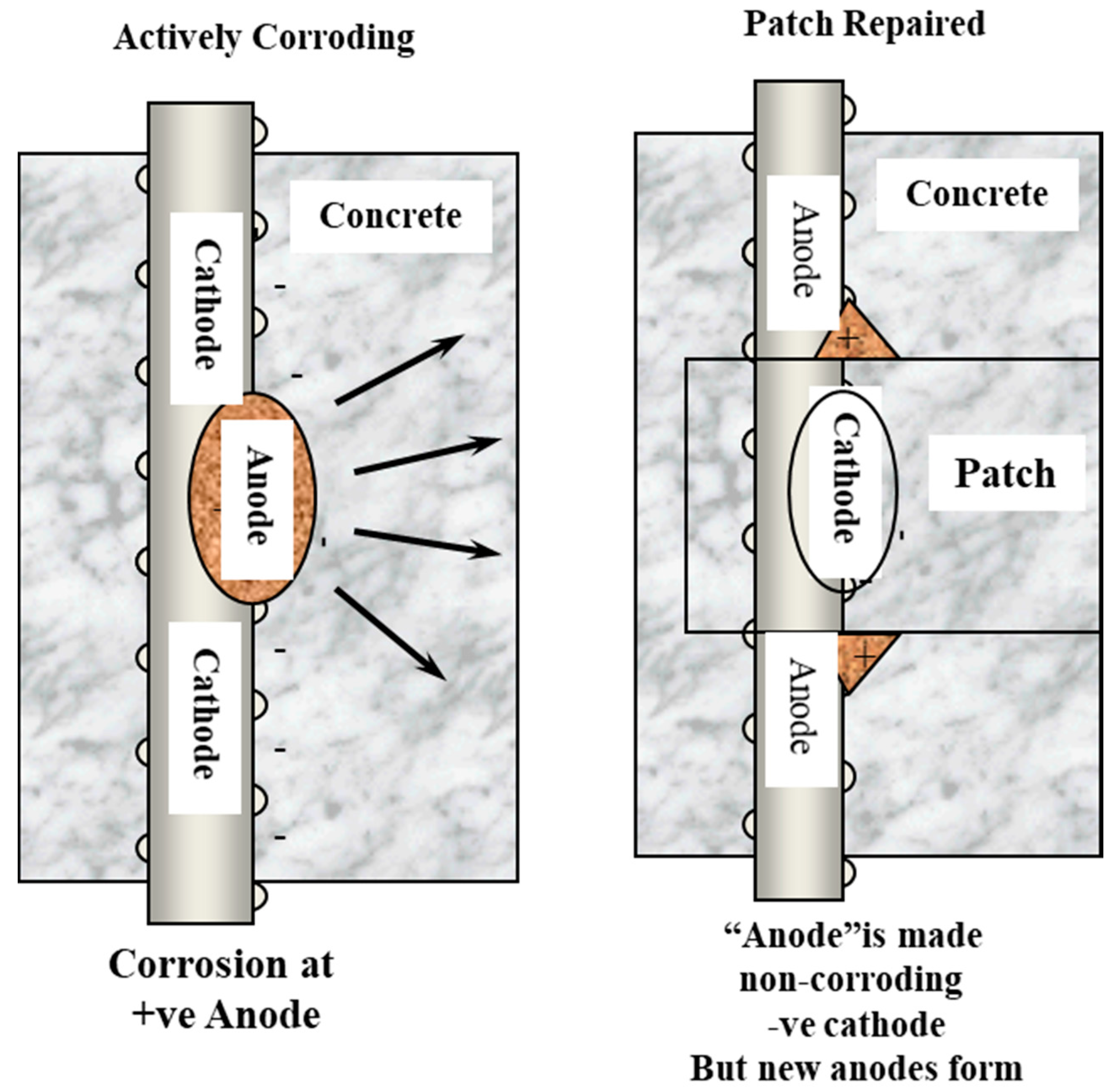
Figure 1. The incipient anode or ring anode effect, where patching creates new anodic corrosion sites around the repair. Reprinted from Ref. [1] with permission. Copyright 2007 Taylor and Francis.
Constrmater 01 00001 g001
Figure 2. Example of multiple patches on a bridge deck due to the incipient anode effect.
Constrmater 01 00001 g002
Figure 3. Mixed metal oxide coated titanium mesh anode being installed on a ridge deck. Courtesy Jack Bennett. Reprinted from Ref. [1] with permission from Taylor and Francis. Copyright 2007 Taylor and Francis.
Constrmater 01 00001 g003
Figure 4. Ribbon anodes in the soffit of a reinforced concrete jetty in Jersey, UK.
Constrmater 01 00001 g004
Figure 5. Probe anodes being installed in a basement wall to protect the reinforcement where there was chloride ingress and through cracks.
Constrmater 01 00001 g005
Figure 6. Conductive coating being applied to reinforced concrete columns and beams on a building in London, England. Reprinted from Ref. [1] with permission. Copyright 2007 Taylor and Francis.
Constrmater 01 00001 g006
Figure 7. Arc-sprayed zinc anode applied to the substructure of a highway bridge in the north of England. Reprinted from Ref. [1] with permission.Copyright 2007 Taylor and Francis.
Constrmater 01 00001 g007
Publisher’s Note: MDPI stays neutral with regard to jurisdictional claims in published maps and institutional affiliations.