Abstract
Induced trench method is a well-known technique usually used to reduce the soil pressure applied on buried pipes. This method involves the use of a lightweight compressible material above the buried pipe to increase the positive arching, and thus, to decrease the soil pressure applied on the buried pipe. However, little efforts have been given by previous studies to check the applicability of using tire-derived aggregate (TDA) as the light weight and compressible material in the induced trench method, where it is not clear if the TDA could be used to increase the positive arching for the case of concrete pipes with different diameters and backfill heights. Thus, this paper investigates the effect of using TDA on the structural performance of buried concrete pipes subjected to soil load using a validated three-dimensional finite element model. A sensitivity analysis has been carried out to examine the effect of the configuration of the TDA, backfill height, and pipe diameter on the performance of the TDA in reducing the pipe wall bending moment. It was found that increasing the backfill height decreases the performance of the TDA. Furthermore, increasing the pipe diameter up to 1.2 m increases the TDA performance. However, the performance of the TDA significantly reduces as the diameter increases from 1.2 m to 2.4 m. In addition, it was also observed that the TDA configuration has a remarkable influence on its performance, where it is necessary to place the TDA layer on top of the pipe crown to increase the positive arching. The results reported in this paper provide useful addition to the literature and will help designers to ensure the economic design of buried pipes using recyclable materials.
1. Introduction
Induced (or imperfect) trench installation has been proposed to enable the economic design of buried concrete pipes taking advantage of the positive soil arching. The mechanism of this method involves the use a compressible and light weight material above the buried pipe to establish a positive soil arching. This positive arching reduces the amount of soil pressure applied on the pipe and thus reduces the pipe wall stress. Most of the previous studies on the induced trench installation focused on the use of the expanded polystyrene geofoam (EPS) [1,2,3,4,5,6,7,8,9,10,11,12,13,14,15,16], sawdust [17,18,19], and Styrofoam chips [20] as the compressible and the lightweight material. However, little efforts have been paid to examine the performance of tire-derived aggregate (TDA) as a compressible material in the induced trench installation technique [21,22,23,24,25,26], although, the TDA is light and has low compressibility. In addition, the use of TDA encourages recycling of used tires as the disposal of old tires became challenging.
Meguid and Youssef [21] investigated the effect of using TDA in part of the backfill on the response of a buried rigid pipe (outer diameter = 0.15 m) using a small-scale laboratory model. The study focused on the soil pressure applied on the pipe and the pipe displacement. However, no insight is given into the pipe wall bending moment and pipe wall stress. Ni et al. [22] developed a two-dimensional finite element model to explore the influence of using TDA on the earth pressure applied on a buried rigid pipe. However, no attention is given to the pipe wall bending moment. Mahgoub and El Naggar [23] studied the effect of using a TDA layer as a backfill soil on the response of a buried steel pipe (outer diameter = 0.2 m) subjected to external load from a newly constructed foundation using three-dimensional finite element analysis. Mahgoub and El Naggar [24] investigated the effect of using TDA as a backfill material and geocell soil reinforcement on top of it on the response of a corrugated steel plate culvert (diameter = 0.6 m) subjected to static external load using laboratory model and three-dimensional finite element analysis. Mahgoub and El Naggar [25] used the same laboratory model and the finite element model developed in their previous publication (Mahgoub and El Naggar [24]) to examine the effect of the TDA configuration on the performance of a corrugated steel plate culvert under external loads, where they examined three TDA configurations to find the optimum configuration which achieved the highest percentage decrease in the culvert wall strain and culvert displacement. Alzabeebee [26] studied the impact of the TDA on the bending moment developed in the wall of a buried concrete pipe subjected to seismic loads using two-dimensional time-history finite element analysis. The TDA is placed in the haunch and bedding areas and the results were also compared with a reference case of a pipe surrounding by a compacted soil in the bedding and haunch areas. He found that the TDA reduced the pipe wall bending moment due to seismic effect by a percentage decrease of 22% to 38%, depending on the earthquake intensity.
Based on the aforementioned discussion, it is evident that the previous studies on the use of the TDA are limited, where very little attention is given in previous publications to the efficiency of the TDA in reducing the bending moment developed in the wall of buried concrete pipes. In addition, no study reported how the TDA configuration, pipe diameter, and backfill height affect the performance of the TDA for the case of buried concrete pipes subjected to soil load. Therefore, the aim of this study is to address these gaps in knowledge by examining the effect of the TDA configuration, backfill height, and pipe diameter on the performance of the TDA in reducing the bending moment of a buried concrete pipe subjected to soil loads.
2. Statement of the Problem
As stated earlier, this paper aims to examine the effect of the TDA configuration, backfill height, and pipe diameter on the TDA performance in reducing the bending moment of the wall of a buried concrete pipe. To address the aim, the case of a pipe buried in different trench conditions and subjected to embankment load (load from soil weight) is considered in this study. Two types of soils are considered as a soil surrounding the pipe and a backfilling soil; these are the well graded sandy soil with a degree of compaction of 90% of the standard Proctor density (referred to as SW90) and silty sand with a degree of compaction of 90% of the standard Proctor density (referred to as ML90). These soils are considered based on the recommendation of the American Association of State Highway and Transportation Officials (AASHTO) to ensure good quality installation, and thus good support condition, of buried concrete pipes [27].
Before defining the conditions of the trenches, it is important to state the terminology of the pipe sections to avoid confusion to the readers; this terminology is shown in Figure 1. In addition, three configurations are considered for the trench to address the aim of the study as shown in Figure 2a–c. For trench configuration 1, the buried pipe is surrounded by either SW90 or ML90 soils (shown in Figure 2a). This configuration corresponds to Type 2 condition for the pipe installation according to the AASHTO [27]. Trench configuration 2 comprises of a buried pipe surrounded by SW90 or ML90 soils, while the backfill comprises of a layer of the TDA with a thickness of 150 mm on top of the pipe crown, followed by SW90 or ML90 soils as shown in Figure 2b. Trench configuration 3 comprises of a buried pipe surrounded by SW90 or ML90 soils in the bedding and haunch areas, and TDA in the shoulders and on top of the crown followed by SW90 or ML90 soils as detailed in Figure 2c.
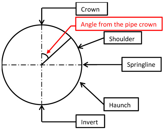
Figure 1.
Terminology of the pipe sections.
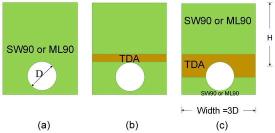
Figure 2.
Trench configurations employed in the present study: (a) trench configuration 1; (b) trench configuration 2; and (c) trench configuration 3.
It is also worthy to state that backfill heights with range of 1.0 m to 3.5 m have been considered in this research. Also, concrete pipes with inside diameter (D) range of 0.3 m to 2.4 m have been examined. Table 1 states the inside diameter and the wall thickness of the concrete pipes utilized in this research; these dimensions are adopted from Alzabeebee et al. [27].

Table 1.
The inside diameter of the pipes used in the research.
3. The Finite Element Model
The three-dimensional finite element method has been used in this research. The simulation model is shown in Figure 3. The dimensions of the model and the mesh size have been considered after conducting a thorough parametric study on the effect of the model width, model length, and mesh size on the results. The depth of the model has been decided assuming that the rock layer is at a depth of 30 m below the surface.
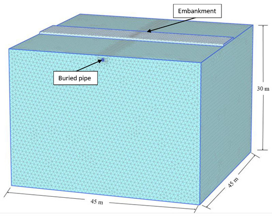
Figure 3.
The mesh of the finite element model of the study.
The buried concrete pipe has been simulated as a shell element similar to many previous studies [27,28]. In addition, the soil has been modelled using 10-noded solid elements. The interaction between the soil and the buried pipe has been simulated using zero thickness interface elements. Standard boundary conditions of the three-dimensional modelling have been considered in the analysis, where the bottom of the model is fully fixed, and the sides of the model are allowed to move in the vertical direction only. These boundary conditions have been repeatedly used in the three-dimensional finite element analysis of soil structure interaction problems [27,28,29,30,31].
The analysis has been conducted in stages, where the first stage involved the calculation of the at-rest earth pressure of the soil before the trench excavation. The second stage involved the simulation of the trench excavation by deactivating the solid elements which represent the trench. The third stage simulated the placement of the bedding layer, the installation of the concrete pipe, and the backfill process. The final stage considered the construction of the embankment.
Finally, it is worthy to state that the general formulation of the utilized static finite element analysis is controlled by Equation (1) [27].
where [] is the global stiffness matrix of the whole system, is the displacement, and is the applied external forces.
4. Material Modelling and Properties
The Mohr–Coulomb model has been utilized to model the subgrade soil (natural soil) due to the simplicity of the model and the availability of its material properties. This model uses a constant stiffness value to represent the behavior of the soil and, thus, it does not consider the effect of the stress level on stiffness. However, the hardening soil model has been used to simulate the behavior of the soil surrounding the pipe (i.e., SW90 and ML90) and the backfill soil, as Katona [32] stated the necessity to use a model that simulates the change of soil stiffness with stress level for accurate modeling of soil–pipe interaction problems. The hardening soil model accounts to the influence of stress level, and the loading and unloading on soil stiffness. This soil model uses Equation (2) to calculate the stiffness of the soil for the case of primary loading (), Equation (3) to calculate the tangent stiffness modulus due to primary loading (), and Equation (4) to determine the unloading/reloading stiffness (). In addition, the TDA has also been simulated using the hardening soil model to accurately model the change of the TDA stiffness as the backfill height rises and, thus, to enable accurate simulation of the soil arching. The failure state in the Mohr–Coulomb model and the hardening soil model is derived according to the Mohr–Coulomb shear strength equation shown in Equation (6). The concrete pipe has been simulated using the linear elastic model similar to many previous studies [27,28,33].
where is the reference drained triaxial stiffness, is the lateral earth pressure, is the cohesion of the soil, is the angle of internal friction, Pref is the stress level at which the hardening soil model parameters are derived, is a factor that controls the effect of the stress state on the stiffness of the soil, is the reference tangent stiffness, is the unloading/reloading reference stiffness, is the at-rest lateral earth pressure, is the vertical earth pressure, and is the shear stress at failure [34,35]. More details on the utilized constitutive models could be found in other studies in the literature [35,36].
The properties of the subgrade soil (natural soil), SW90, and ML90 are collected from available studies in the literature [37,38,39,40,41,42] and are shown in Table 2. The TDA properties are adopted from Mahgoub and El Naggar [23], who proposed these properties based on a numerical calibration of high-quality experimental results. These properties are also listed in Table 2. In addition, the modulus of elasticity and Poisson’s ratio of the concrete are considered equal to 24,000,000 kPa and 0.2, respectively [33,34]. Furthermore, the interface reduction coefficient of the interface elements between the soil and the buried pipe is taken equal to 0.7 as used in previous studies [33].
Table 2.
The properties of the SW90, ML90, TDA, and subgrade soil used in the research.
5. Validation
The validation involved modelling the full-scale test conducted by MacDougall [43] to assess the abilities of the developed three-dimensional finite element model in predicting the bending moment of a buried concrete pipe subjected to combined soil and traffic loads. MacDougall [43] carried out the aforementioned full-scale test to calculate the bending moment of a buried reinforced concrete pipe buried with a backfill height of 0.6 m and subjected to the AASHTO standard dual-tire load (which is equal to 100 kN and applied on a contact area of 0.25 × 0.50 m). The concrete pipe had an inside diameter of 0.6 m and a wall thickness of 0.094 m. In addition, the concrete compressive strength (fc′) was equal to 66 MPa. Furthermore, the soil surrounding the pipe was poorly graded sandy gravel with a minimum degree of compaction of 90 percent of the standard Proctor dry density.
This problem has been modelled in this research to assess the accuracy of the finite element model. The modelling methodology explained in Section 3 has been used in this section. In addition, the backfill soil has been modelled using the properties of the SW90 with the properties listed in Table 1, as the previous studies provided the same constitutive properties for the well graded sand and the sandy gravel soil at a compaction percentage of 90% of the standard Proctor dry density (refer to Alzabeebee [44] for further details). In addition, the concrete pipe has been modelled using the linear elastic model. The modulus of elasticity for the concrete has been considered equal to 38,450 MPa calculated using the value of the compressive strength reported by MacDougall [43] (i.e., 66 MPa). Furthermore, the unit weight and the Poisson’s ratio (ν) of the pipe have been assumed to be equal to 25 kN/m3 and 0.2, respectively.
Figure 4 compares the results of the bending moment developed in the concrete pipe wall obtained from the present study and the experimental results of MacDougall [43]. The figure also reports the results of the same problem obtained by Alzabeebee et al. [27], who used the same problem to validate the results of Midas GTX/NX software package. By looking at Figure 4, it can be noticed that there is a good agreement between the results obtained from the present study and the full-scale test results. In addition, the obtained results are also in good agreement with the results of the numerical model of Alzabeebee et al. [27]. Therefore, it is obvious that the model developed in the present study is capable of capturing the observed behavior. Thus, these results give certainty in the methodology adopted in this study.
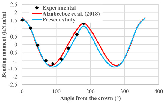
Figure 4.
Calculated and predicted bending moment values developed in the pipe wall for a concrete pipe buried with backfill height of 0.6 m and subjected to the AASHTO standard dual-tire load [27].
6. Results
The following subsections discuss the results obtained from the parametric study. It is worthy to mention that only the results of the bending moment developed in the wall of the buried concrete pipe are displayed in this section as the bending moment is the only parameter that is used usually in the routine design of concrete pipes according to the indirect design method [28,34]. Notably, the bending moment is taken directly from the results of the shell elements as the formulation of these elements allows the calculation of the bending moment in the finite element analysis.
6.1. Effect of the TDA on the Development of the Bending Moment in the Pipe Wall
Firstly, the effect of the TDA configuration on the distribution of the bending moment around the pipe wall is examined by inspecting the bending moment developed in the pipe wall for the case of the conventional backfill using SW90 soil (CB (SW90)), conventional backfill using ML90 (CB (ML90)), TDA configuration 1 (TDA 1), and TDA configuration 2 (TDA 2). The case of a backfill height of 1.0 m is selected for this task. Figure 5 and Figure 6 present the results of the effect of the TDA configuration on the distribution of the bending moment for SW90 backfill and ML90 backfill, respectively. The angle from the pipe crown in both figures is measured as indicated in Figure 1. Looking at Figure 5 and Figure 6, it is clear that both figures show that the presence of the TDA reduces the bending moment, however, it does not influence the trend of the relationship of the developed bending moment in the pipe wall. In addition, it is also clear that the TDA 1 achieved lower bending moment values compared to the TDA 2 and for both backfill cases (SW90 and ML90).
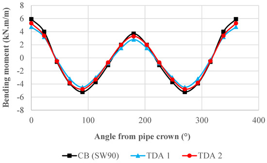
Figure 5.
Comparison of the bending moment developed in the pipe wall for conventional backfill using SW90, TDA 1, and TDA 2 for SW90 backfill.
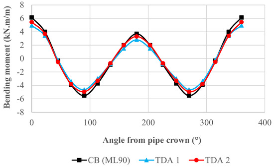
Figure 6.
Comparison of the bending moment developed in the pipe wall for conventional backfill using ML90, TDA 1, and TDA 2 for ML90 backfill.
6.2. Perfromance of the TDA for Different Backfill Heights
The effect of the backfill height on the structural response of the buried pipe for conventional and TDA trench configurations is examined in this section. Figure 7 and Figure 8 depict the relationship between the maximum bending moment in the pipe wall and the backfill height for the three trench configurations for the SW90 backfill and ML90 backfill, respectively. Both figures reveal an increase in the maximum bending moment as the backfill height increases, which is due to the increase of the applied soil weight on the pipe for the three trench configurations [27,45,46]. Similar observation is also reported by Akyelken and Kılıç [16] and Kang [47]. It can also be observed from the figures that, as expected, the TDA reduces the maximum bending moment for both backfill soils (i.e., SW90 and ML90). This is due to the low compressibility of the TDA material which helps to make the soil prism on top of the pipe settle more than its surroundings and, thus, the generated shear along the sides of the soil prism sheds the soil pressure away from the pipe. Moreover, it can be noticed from both figures that the TDA 1 is better in decreasing the maximum bending moment of the pipe when compared to the TDA 2. This means that the TDA 1 configuration develops more positive arching compared to the TDA 2. This is because the layer of the TDA in the TDA 1 configuration was confined and contained by a strong medium from top and bottom, this confinement increased the effectiveness of the TDA layer in shedding the soil pressure away [48].
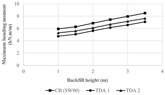
Figure 7.
Effect of the backfill height on the maximum bending moment for the three trench configurations considering the SW90 as a backfill soil.
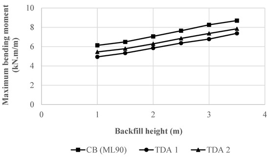
Figure 8.
Effect of the backfill height on the maximum bending moment for the three trench configurations considering the ML90 as a backfill soil.
To provide better insight into the effectiveness of the TDA in terms of the percentage decrease of the maximum bending moment, Figure 9 and Figure 10 present the percentage decrease of the maximum bending moment for TDA 1 and TDA 2 configurations and for the SW90 backfill and ML90 backfill, respectively. Both figures show that increasing the backfill height reduces the percentage decrease of the maximum bending moment for both TDA configurations. This means that the positive arching decreases as the soil weight increases. In addition, the figures clearly show that the TDA 1 provides better effectiveness for both backfill conditions compared to the TDA 2. Furthermore, comparing the results of Figure 9 and Figure 10 show that the percentage decrease is approximately similar for both backfills. For the SW90 backfill, the maximum percentage decrease of the maximum bending moment is equal to 20% and 11% for the TDA 1 and TDA 2, respectively. For the ML90 backfill, the maximum percentage decrease of the maximum bending moment is equal to 19% and 11% for the TDA 1 and TDA 2, respectively.
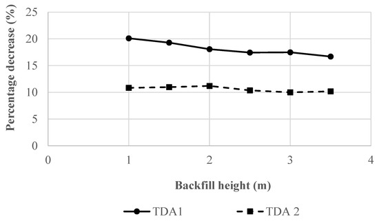
Figure 9.
Percentage decrease of the maximum bending moment using TDA 1 and TDA 2 trench configurations for the SW90 backfill.
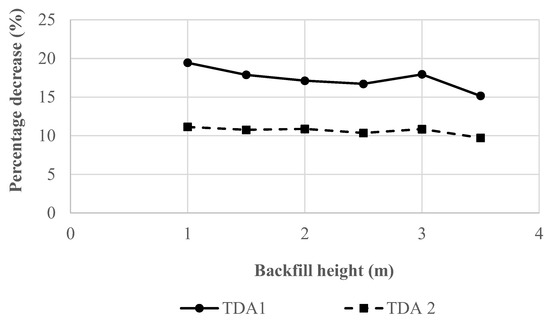
Figure 10.
Percentage decrease of the maximum bending moment using TDA 1 and TDA 2 trench configurations for the ML90 backfill.
6.3. Performance of the TDA for Different Diamaters
Figure 11, Figure 12 and Figure 13 present the effect of the pipe diameter on the maximum pipe wall bending moment for the CB (SW90), TDA 1, and TDA 2, respectively. The figures show that the maximum bending moment increases approximately linearly as the backfill height rises for all of the diameters modelled in this study, which is due to the dramatic increase of the soil pressure applied on the pipe as the weight of the soil on top of the pipe rises [27].
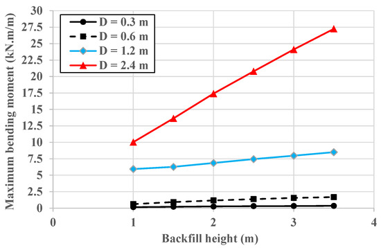
Figure 11.
Effect of the pipe diameter and backfill height on the maximum pipe wall bending moment for the CB (SW90).
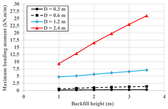
Figure 12.
Effect of the pipe diameter and backfill height on the maximum pipe wall bending moment for the TDA 1.
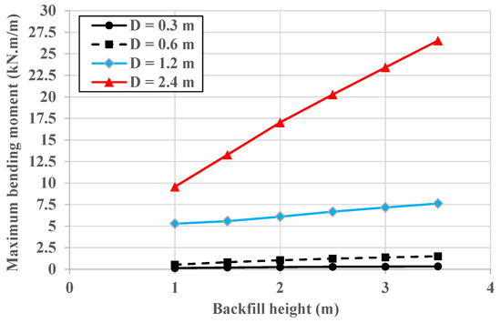
Figure 13.
Effect of the pipe diameter and backfill height on the maximum pipe wall bending moment for the TDA 2.
Figure 14 and Figure 15 show the percentage decrease of the maximum bending moment due to the use of TDA 1 and TDA 2, respectively. For both TDA configurations in general, the percentage decrease rises as the diameter changes from 0.3 m to 1.2 m, then significantly declines as the pipe diameter becomes equal to 2.4 m. This could be justified by the complicated interaction between the soil arching and the increase of the weight of the soil applied on the pipe for the case of a pipe with a diameter of 2.4 m. In addition, it is evident that the percentage decrease declines as the backfill height rises and then stabilizes at a certain backfill height. The stabilization of the percentage decrease means that the arching factor stabilizes at a certain backfill height.
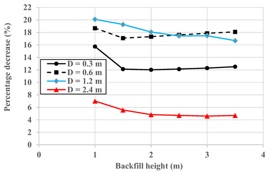
Figure 14.
Effect of the pipe diameter and backfill height on the percentage decrease of the maximum bending moment for the TDA 1.
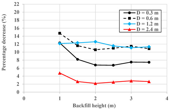
Figure 15.
Effect of the pipe diameter and backfill height on the percentage decrease of the maximum bending moment for the TDA 2.
Comparing Figure 14 and Figure 15 shows that the TDA 1 performs better than the TDA 2 as the latter scored a lower percentage decrease.
Finally, it is worthy to state that the results seem to be inconclusive for Figure 7, Figure 8, Figure 11, Figure 12 and Figure 13 and there is no backfill height at which the increase of the bending moment stops. As stated earlier, this is due to the increase of the soil weight as the backfill height rises and, thus, there is no point at which the increase of the bending moment stops due to the continuous increase of the soil weight.
7. Conclusions
The paper reported the results of a validated numerical analysis of the effect of the tire-derived aggregate (TDA) configuration, backfill height, and pipe diameter on the performance of tire-derived aggregate in reducing the bending moment of buried concrete pipes subjected to embankment load (i.e., soil weight). The study reported new results that are not available in the literature and provided an insight into the performance of the TDA for different scenarios. The innovation of the paper is that it utilized a verified methodology to show the feasibly of using the TDA in an economic design application that is urgently needed. The following could be stated based on the scientific content provided in this research work:
- -
- In general, it has been noticed that the TDA configuration has a remarkable influence on the performance of the TDA, where it is necessary to place the TDA layer on top of the pipe crown to enable more positive arching. Therefore, the designer should specify the configuration of the TDA for site engineers and supervise the installation to ensure that the TDA provides its best performance.
- -
- Increasing the backfill height decreases the beneficial effect of the TDA, where the percentage decrease of the maximum bending moment declines as the backfill height rises then stabilizes. Thus, the use of the TDA should be suggested for pipes buried with shallow depths.
- -
- In general, increasing the diameter of the pipe from 0.3 m to 1.2 m remarkably enhances the ability of the TDA in decreasing the maximum bending moment. However, the beneficial effect shrinks as the diameter rises further to 2.4 m. This means that the TDA could be used to increase positive soil arching, and thus, ensure economic design of buried pipes with a diameter range of 0.3 m to 1.2 m.
Author Contributions
Conceptualization, S.A. and S.K.; methodology, S.A. and S.M.A.; software, S.A. and S.M.A.; validation, S.M.A.; formal analysis, S.M.A.; investigation, S.A. and S.K.; resources, S.K.; data curation, S.M.A.; writing—original draft preparation, S.A. and S.K.; writing—review and editing, S.K.; visualization, S.A. and S.M.A.; supervision, S.A.; project administration, S.A.; funding acquisition, S.K. All authors have read and agreed to the published version of the manuscript.
Funding
This research received no external funding.
Institutional Review Board Statement
Not applicable.
Informed Consent Statement
Not applicable.
Data Availability Statement
Not applicable.
Conflicts of Interest
The authors declare no conflict of interest.
References
- McAffee, R.P.; Valsangkar, A.J. Field performance, centrifuge testing, and numerical modelling of an induced trench installation. Can. Geotech. J. 2008, 45, 85–101. [Google Scholar] [CrossRef]
- Kim, H.; Choi, B.; Kim, J. Reduction of earth pressure on buried pipes by EPS geofoam inclusions. Geotech. Test. J. 2010, 33, 304–313. [Google Scholar] [CrossRef]
- McGuigan, B.L.; Valsangkar, A.J. Centrifuge testing and numerical analysis of box culverts installed in induced trenches. Can. Geotech. J. 2010, 47, 147–163. [Google Scholar] [CrossRef]
- McGuigan, B.L.; Valsangkar, A.J. Earth pressures on twin positive projecting and induced trench box culverts under high embankments. Can. Geotech. J. 2011, 48, 173–185. [Google Scholar] [CrossRef]
- Vaslestad, J.; Sayd, M.S.; Johansen, T.H.; Wimen, L. Load reduction and arching on buried rigid culverts using EPS geofoam. Design metho and instrumented field tests. In Proceedings of the EPS, Lillestrom, Norway, 27 June–1 July 2011; p. 36. [Google Scholar]
- Oshati, O.S.; Valsangkar, A.J.; Schriver, A.B. Earth pressures exerted on an induced trench cast-in-place double-cell rectangular box culvert. Can. Geotech. J. 2012, 49, 1267–1284. [Google Scholar] [CrossRef]
- Bartlett, S.F.; Lingwall, B.N. Protection of pipelines and buried structures using EPS geofoam. Ground Improv. Geosynth. 2014, 547–556. [Google Scholar] [CrossRef]
- Bartlett, S.F.; Lingwall, B.N.; Vaslestad, J. Methods of protecting buried pipelines and culverts in transportation infrastructure using EPS geofoam. Geotex. Geomemb. 2015, 43, 450–461. [Google Scholar] [CrossRef]
- Witthoeft, A.F.; Kim, H. Numerical investigation of earth pressure reduction on buried pipes using EPS geofoam compressible inclusions. Geosynth. Int. 2016, 23, 287–300. [Google Scholar] [CrossRef]
- Khalaj, O.; Azizian, M.; Tafreshi, S.M.; Mašek, B. Laboratory investigation of buried pipes using geogrid and EPS geofoam block. IOP Conf. Ser. Earth Environ. Sci. 2017, 95, 022002. [Google Scholar] [CrossRef]
- Meguid, M.A.; Hussein, M.O.G. A numerical procedure for the assessment of contact pressures on buried structures overlain by EPS geofoam inclusion. Int. J. Geosynth. Ground Eng. 2017, 3, 1–14. [Google Scholar] [CrossRef]
- Meguid, M.A.; Hussein, M.G.; Ahmed, M.R.; Omeman, Z.; Whalen, J. Investigation of soil-geosynthetic-structure interaction associated with induced trench installation. Geotex. Geomemb. 2017, 45, 320–330. [Google Scholar] [CrossRef]
- Al-Naddaf, M.; Han, J.; Xu, C.; Rahmaninezhad, S.M. Effect of geofoam on vertical stress distribution on buried structures subjected to static and cyclic footing loads. J. Pipeline Syst. Eng. Pract. 2019, 10, 04018027. [Google Scholar] [CrossRef]
- Ma, Q.; Ku, Z.; Xiao, H. Model tests of earth pressure on buried rigid pipes and flexible pipes underneath expanded polystyrene (EPS). Adv. Civ. Eng. 2019, 9156129. [Google Scholar] [CrossRef]
- Khalaj, O.; Azizian, M.; Joz Darabi, N.; Moghaddas Tafreshi, S.N.; Jirková, H. The role of expanded polystyrene and geocell in enhancing the behavior of buried HDPE pipes under trench loading using numerical analyses. Geosciences 2020, 10, 251. [Google Scholar] [CrossRef]
- Akyelken, F.A.; Kılıç, H. Experimental and Numerical Analyses of Buried HDPE Pipe with Using EPS Geofoam. KSCE J. Civ. Eng. 2022, 26, 3968–3977. [Google Scholar] [CrossRef]
- McAffee, R.P.; Valsangkar, A.J. Performance of an induced trench installation. Transport. Res. Rec. 2005, 1936, 230–237. [Google Scholar] [CrossRef]
- Parker, B.A.; McAffee, R.P.; Valsangkar, A.J. Field performance and analysis of 3-m-diameter induced trench culvert under a 19.4-m soil cover. Transport. Res. Rec. 2008, 2045, 68–76. [Google Scholar] [CrossRef]
- McGuigan, B.L.; Oshati, O.S.; Parker, B.A.; Valsangkar, A.J. Post-construction performance of induced trench rigid culverts. Can. Geotech. J. 2016, 53, 1807–1821. [Google Scholar] [CrossRef]
- Turan, A.; El Naggar, M.H.; Dundas, D. Investigation of induced trench method using a full scale test embankment. Geotech. Geolog. Eng. 2013, 31, 557–568. [Google Scholar] [CrossRef]
- Meguid, M.A.; Youssef, T.A. Experimental investigation of the earth pressure distribution on buried pipes backfilled with tire-derived aggregate. Transp. Geotechn. 2018, 14, 117–125. [Google Scholar] [CrossRef]
- Ni, P.; Qin, X.; Yi, Y. Numerical study of earth pressures on rigid pipes with tire-derived aggregate inclusions. Geosynth. Int. 2018, 25, 494–506. [Google Scholar] [CrossRef]
- Mahgoub, A.; El Naggar, H. Using TDA as an engineered stress-reduction fill over preexisting buried pipes. J. Pipeline Syst. Eng. Pract. 2019, 10, 04018034. [Google Scholar] [CrossRef]
- Mahgoub, A.; El Naggar, H. Coupled TDA—Geocell stress-bridging system for buried corrugated metal pipes. J. Geotech. Geoenviron. Eng. 2020, 146, 04020052. [Google Scholar] [CrossRef]
- Mahgoub, A.; El Naggar, H. Innovative application of tire-derived aggregate around corrugated steel plate culverts. J. Pipeline Syst. Eng. Pract. 2020, 11, 04020025. [Google Scholar] [CrossRef]
- Alzabeebee, S. Tire Derived Aggregate as a Sustainable Technique to Mitigate Transient Seismic Effect on Buried Concrete Pipes. Sustain. Cities Resil. 2022, 183, 317–328. [Google Scholar] [CrossRef]
- Alzabeebee, S.; Chapman, D.N.; Faramarzi, A. Development of a novel model to estimate bedding factors to ensure the economic and robust design of rigid pipes under soil loads. Tunn. Undergr. Sp. Technol. 2018, 71, 567–578. [Google Scholar] [CrossRef]
- Alzabeebee, S.; Chapman, D.N.; Faramarzi, A. Economical design of buried concrete pipes subjected to UK standard traffic loading. Proc. Inst. Civ. Eng. Struct. Build. 2019, 172, 141–156. [Google Scholar] [CrossRef]
- Umravia, N.B.; Solanki, C.H. Numerical Analysis To Study Lateral Behavior of Cement Flyash Gravel Piles Under the Soft Soil. Int. J. Eng. 2022, 35, 2111–2119. [Google Scholar] [CrossRef]
- Ali, A.H.; Abbas, H.O.; Abed-Awn, S.H. Behavior of raft foundation built on layered soil under different earthquake excitation. Int. J. Eng. 2022, 35, 1509–1515. [Google Scholar] [CrossRef]
- Zarinfar, M. Investigating the Effect of Soil Layering on Soil-structure Interaction under Seismic Load. Int. J. Eng. 2022, 35, 1989–2006. [Google Scholar] [CrossRef]
- Katona, M.G. Influence of soil models on structural performance of buried culverts. Int. J. Geomech. 2017, 17, 04016031. [Google Scholar] [CrossRef]
- Alzabeebee, S. Seismic response and design of buried concrete pipes subjected to soil loads. Tunn. Undergr. Sp. Technol. 2019, 93, 103084. [Google Scholar] [CrossRef]
- Alzabeebee, S. A comparative study of the effect of the soil constitutive model on the seismic response of buried concrete pipes. J. Pipeline Sci. Eng. 2022, 2, 87–96. [Google Scholar] [CrossRef]
- Alzabeebee, S. Seismic settlement of a strip foundation resting on a dry sand. Nat. Hazards 2020, 103, 2395–2425. [Google Scholar] [CrossRef]
- Alzabeebee, S. Influence of soil model complexity on the seismic response of shallow foundations. Geomech. Eng. 2021, 24, 193–203. [Google Scholar] [CrossRef]
- Boscardin, M.D.; Selig, E.T.; Lin, R.S.; Yang, G.R. Hyperbolic parameters for compacted soils. J. Geotech. Eng. 1990, 116, 88–104. [Google Scholar] [CrossRef]
- Simpson, Gumpertz & Heger. Appendix an Investigation of Suitable Soil Constitutive Models for 3-D Finite Element Studies of Live Load Distribution through Fills onto Culverts. Available online: http://onlinepubs.trb.org/onlinepubs/nchrp/nchrp_rpt_647appendixa.pdf (accessed on 6 October 2022).
- Bowers, J.T.; Webb, M.C.; Beaver, J.L. Soil Parameters for Design with the 3D PLAXIS Hardening Soil Model. Transport. Res. Rec. 2019, 2673, 708–713. [Google Scholar] [CrossRef]
- Thompson, M.R.; Elliott, R.P. ILLI-PAVE based response algorithms for design of conventional flexible pavements. Transport. Res. Rec. 1985, 1043, 50–57. [Google Scholar]
- Garber, N.J.; Hoel, L.A. Traffic and Highway Engineering, 4th ed.; University of Virginia, Cengage Learning: Charlottesville, VA, USA, 2009. [Google Scholar]
- Huang, Y.H. Pavement Analysis and Design; Pearson Prentice Hall: Upper Saddle River, NJ, USA, 2004. [Google Scholar]
- MacDougall, K. Behaviour and Design of Reinforced Concrete Pipes. Master’s Thesis, Queen’s University, Kingston, ON, Canada, 2014. [Google Scholar]
- Alzabeebee, S. Enhanced Design Approaches for Rigid and Flexible Buried Pipes Using Advanced Numerical Modelling. Ph.D. Thesis, University of Birmingham, Birmingham, UK, 2017. [Google Scholar]
- Alzabeebee, S.; Chapman, D.N.; Faramarzi, A. Innovative approach to determine the minimum wall thickness of flexible buried pipes. Geomech. Eng. 2018, 15, 755–767. [Google Scholar] [CrossRef]
- Liu, H.; Xiao, Y.; Liu, K.; Zhu, Y.; Zhang, P. Numerical Simulation on Backfilling of Buried Pipes Using Controlled Low Strength Materials. Appl. Sci. 2022, 12, 6901. [Google Scholar] [CrossRef]
- Kang, J. Finite element analysis for deeply buried concrete pipes in proposed imperfect trench installations with expanded polystyrene (EPS) foams. Eng. Struct. 2019, 189, 286–295. [Google Scholar] [CrossRef]
- Bosscher, P.J.; Edil, T.B.; Eldin, N.N. Construction and performance of a shredded waste tire test embankment. Transport. Res. Rec. 1992, 1345, 44–52. [Google Scholar]


Publisher’s Note: MDPI stays neutral with regard to jurisdictional claims in published maps and institutional affiliations. |
© 2022 by the authors. Licensee MDPI, Basel, Switzerland. This article is an open access article distributed under the terms and conditions of the Creative Commons Attribution (CC BY) license (https://creativecommons.org/licenses/by/4.0/).