Abstract
Evaluation of the sliding stability of concrete dams requires the use of numerical tools not only able to simulate the coupled hydromechanical behavior but also able to adequately represent the foundation discontinuities and the specific features of dam foundations. The formulation of a three-dimensional (3D) small displacement finite element model based on interface elements to simulate the discontinuities is presented. In this model, the hydraulic behavior is simulated assuming that the water flow occurs only along channels located at the edges of the triangular interface elements that simulate the discontinuities. The model is used to perform coupled hydromechanical analysis of a large arch-gravity dam and to assess safety against dam base sliding, assuming different constitutive models at the dam/foundation interface and two different approaches: (i) strength reduction method and (ii) amplification of the hydrostatic pressure, assuming an increase in the reservoir level. The present study shows that consistent results are obtained with the proposed numerical model and that stability analysis should preferably be carried out using the method of increasing the hydrostatic pressure and the corresponding uplift pressures, as this methodology leads to significantly lower safety factors.
1. Introduction
Concrete dams allow fresh water to be stored for a variety of functions such as irrigation and water supply, flood control, hydropower production (renewable energy generated without polluting the atmosphere), protection of estuaries against flooding tides, improvement of navigation along rivers and recreation. It is thus vital to ensure the continued economic use and enjoyment of these structures as human life depends on freshwater and on the benefits provided by dams. Regarding sustainability, it is necessary to guarantee that concrete dams, with an expected lifetime of about 50 years, remain operational as long as possible, in order to avoid new constructions and thus minimize their effect on the environment. In addition, concrete dams must remain safe, as any failure may lead to a great loss of human lives, environmental disasters and huge economic losses. Therefore, the prevention of dam failures is a key issue.
In concrete dams, the majority of recorded failures were due to problems in the foundation rock mass, due to a loss of strength, and a lack of shear resistance in weak planes of unfavorable direction. The behavior of this zone is influenced by the transfer of loads from the dam body to the foundation. The main static loads to be taken into account in normal operating conditions are the hydrostatic pressure and variations in ambient temperature, and therefore it is necessary to develop numerical tools which not only allow the coupled analysis between mechanical, hydraulic and thermal behaviors to be performed, in an integrated manner, but also allow the representation of rock mass discontinuities through which the majority of the water flows and allow the simulation of both grout curtain and drainage systems installed in the dam foundations.
The complex coupled hydromechanical behavior of the foundation rock masses needs to be further studied in situ and adequately analyzed using numerical models. Three-dimensional (3D) models are required for stability analysis of concrete arch dams as, in this case, failure mechanisms involving intersecting planes cannot be modeled two-dimensionally. These 3D models are also required in the analysis of gravity and arch-gravity dams when the dam height is variable along its axis or when the geotechnical conditions are not uniform [1,2]. However, there are no commercial numerical tools able to address the hydromechanical behavior of the dam foundation and perform the subsequent stability analysis in a 3D integrated manner [3]. The hydromechanical effect of the intersection of discontinuities is a difficult issue, especially in 3D, due to the complexity in handling fracture system geometry and connectivity. Thus, simplified methodologies have been used in which the hydraulic and the mechanical behaviors are analyzed in an uncoupled way and stability is evaluated separately [4,5], but, from the point of view of a practitioner engineer, such procedures are difficult to apply.
Fully coupled two-dimensional (2D) hydromechanical analyses of the water flow through the rock mass discontinuities of operating dams were presented by several authors [6,7,8,9], some of them allowing the comparison between numerical results and those recorded in situ. The majority of these studies use discontinuum models, which simulate the hydromechanical interaction and therefore provide a means of assessing the stability of the dam, taking into account the actual shear displacements and aperture of discontinuities, and the water pressure pattern within the foundation.
In the dam engineering field, several authors in the 1980s presented different 3D finite element (FE) models which allowed coupled analysis of the hydromechanical behavior of rock mass foundations, based on the first fully coupled hydromechanical method, in 2D [10]. These 3D FE models were mainly used in research activities in order to assess the influence of the grout curtain´s dip angle on the stresses and deformations of a large arch dam [11], to highlight the relevance of taking into account seepage forces at the rock mass foundation discontinuities in the interaction between the dam and the foundation and in stability analysis of arch dams [12,13,14] and for the analysis of the hydromechanical behavior of concrete dams [15]. The fully coupled FE 3D model presented by [16] resorted to the poroelasticity theory to simulate the deformability of the rock matrix and seepage through a porous medium and simulated seepage through the foundation discontinuities using the cubic law in the laminar regime. However, the model simulated only linear elastic mechanical behavior and required a large quantity of computational memory, even for simple problems, as it used a numerical implicit technique (the global matrix of the hydromechanical model included degrees of freedom of both the mechanical and the hydraulic models). The explicit hydromechanical model presented in [17] as an extension to the code 3DEC, based on discrete elements, avoided the need of using large dimension matrices.
In the past decades, most of the research and development on hydromechanical coupling in fractured rocks and most applications of hydromechanical coupled analysis have been conducted as part of oil and gas exploration, hot dry rock geothermal energy investigations and studies for nuclear waste disposal [18,19].
Thus, the application of research results to the field conditions of dam foundations is still difficult. Therefore, there is the need to develop and/or incorporate models of other scientific areas in the dam engineering foundation field, in order to allow adequate interpretation of dam foundation behavior (e.g., [20,21,22]).
The hydromechanical behavior of dam foundations began to receive wide attention in the early 1960s [23,24,25] and is still the subject of extensive laboratory and in situ research [26,27,28].
Regarding stability assessment of concrete dams, some dam design guidelines recommend simplified stability analysis procedures considering a zero cohesion and tensile strength interface model [29]. In fact, joints are the weakest region of the rock mass and the part most prone to failure [30]. However, the dam/foundation interface exhibits cohesion and tensile strength, which gradually decrease as sliding occurs [31,32]. Thus, sliding stability analysis of concrete dams for static and seismic loads may be improved by incorporating fracture energy concepts which allow better representation of the actual material behavior (concrete/rock interface with cohesion) [33,34].
The present study is motivated by the need to improve the current sliding safety assessment of concrete dams. For this purpose, the authors propose a methodology that allows safety analysis to be carried out taking into account the specific features and hydromechanical behavior of dam foundations. This paper starts by describing in detail the formulation of the 3D discontinuum hydromechanical model used in this study, implemented in the numerical code Parmac3D-Fflow, which is a small displacement finite element model for coupled hydromechanical analysis of concrete dam foundations, developed from the 2D version of the same code [8,35]. The authors propose the use of a simplified model to simulate the hydraulic behavior, assuming that seepage takes place along channels located at the edges of the interface elements which simulate the discontinuities. To show the full capability of the code and the graphical representation of the results, a global three-dimensional model of a large arch-gravity dam was developed followed by hydromechanical analysis. The safety of the dam/foundation system against dam base sliding was assessed using two different approaches: (i) strength reduction method and (ii) amplification of the hydrostatic pressure, assuming an increase in the reservoir level. These analyses, carried out using different constitutive models to describe the behavior of the dam/foundation interface, led to different safety factors. Finally, a critical discussion of the results obtained is presented.
2. Governing Equations and Numerical Code
The 3D discontinuum hydromechanical model used in this study performs a fully coupled hydromechanical analysis, where fracture conductivity is dependent on mechanical deformation and the mechanical behavior is affected by water pressures. The code presented here, Parmac3D-Fflow, is an extension to 3D of a 2D code previously developed, which has been used in both static and dynamic analysis of gravity dam foundations [8] and is part of a computational model initially developed for concrete fracture analysis [33].
2.1. Mechanical Model
The mechanical model implemented in code Parmac3D-FFlow is a model of discrete nature and uses an explicit solution algorithm based on the centered difference method [33,36]. The domain is divided into a group of blocks which interact with each other, and this interaction between blocks must be face to face. The contact surfaces between adjacent blocks are fully compatible and the interfaces can slip and separate. Each model block is internally divided into a tetrahedral mesh in order to simulate material deformability.
Each block is internally divided into tetrahedra. For a given nodal point, the equations of motion are given by:
where is the velocity, is the acceleration, is the damping constant, proportional to the velocity, m is the nodal mass, is the acceleration due to gravity and are the nodal forces applied at a given instant of time, defined by three parts:
where are the external forces applied at the nodal point, are the external forces due to the contact with neighboring blocks which only occurs at nodal points located at the block boundaries and are the internal forces due to the deformation of the associated plane finite elements [37]. The integration of Equation (1) is done based on the centered difference method which is conditionally stable. The definition of the calculation step and of the solution scheme to be used when only the static solution of the problem is required may be found in [33,36].
2.1.1. Joint Elements
The interaction between blocks is achieved by means of interface finite elements, which are adequate for analysis in small displacements [38,39]. Andjelkovic et al. [40] stated that the design of concrete dams is based on the main assumption that they are relatively rigid structures that allow very small movement at the contact with the rock mass. Studies presented by Farinha et al. [8] show that the hypothesis of small displacements is valid both in the analysis of the hydromechanical behavior of concrete dam foundations and in stability analysis for static and dynamic conditions. When large displacement analysis is required, the hybrid algorithm proposed in [8] can be used.
In Parmac3D-Fflow, joint elements are used to simulate the discontinuities and tetrahedral or hexahedral elements are used to simulate the domain. Figure 1 shows the interaction between two tetrahedral blocks and the corresponding triangular interface element in small displacements used in the mechanical part of the 3D hydromechanical coupled model. Figure 2 shows the interaction between two hexahedral blocks and the corresponding eight-node interface element, which is divided into eight triangles by including an extra node (slave node shown in red) at the center of the element face. This division into triangular elements is necessary as the hydraulic model is defined for triangles.
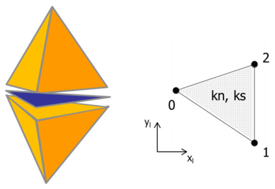
Figure 1.
Triangle joint element in small displacements in a mesh of tetrahedral finite elements.
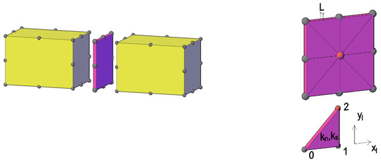
Figure 2.
Eight-node joint element divided into triangular elements in a mesh of 20-node hexahedral finite elements.
The 3D model is developed in a similar way to that for 2D, in which the joint element allows a discontinuity in the displacement field, based on a direct relation between stresses and displacements. In each joint element integration point, the stresses in the local axes are given by:
where and are the normal and shear stresses at time step t; and are the elastic estimates of both normal and shear stresses at the next time step; and are the displacement increments in both normal and tangential joint directions, taking into account the displacement of the nodal points of the joint; and and are the normal and shear contact stiffnesses, associated with the joint element.
The joint constitutive model is based on estimates of stresses and foreseen values are amended, if necessary.
Integration points are coincident with the position of the joint element nodes at the midplane, whose coordinates are given by the average of the coordinates of the nodal points of the triangular plane elements at each side of the joint.
2.1.2. Mesh Compatibility
The use of interface finite elements requires compatible finite element meshes, so that the same numerical discretization is obtained at the faces of blocks in contact, in order to ensure that all interactions are of the triangular face to triangular face type.
In two-dimensional (2D) models, where interactions are edge to edge, mesh compatibility is relatively simple [8,35], but in 3D the process of ensuring that the interaction between blocks is always face to face is much more complex. This algorithm is still being developed, and therefore the mesh of the dam/foundation system presented in the following section and used to perform sliding stability analysis is a regular mesh, in order to ensure perfect compatibility.
In the joint finite element, as there is perfect compatibility of the displacement field along the interfaces, a more accurate representation of the stress distribution along the joints is obtained in comparison to formulations based on traditional discrete elements with similar discretization [3].
2.1.3. Constitutive Models of the Joint Element
In safety assessment of concrete dams, linear elastic behavior of the dam concrete, of the dam contraction joints and of the foundation rock mass is usually assumed. At the dam/foundation interface, the Mohr–Coulomb failure criterion is frequently adopted, complemented with a tensile strength criterion.
However, there is cohesion and there is tensile strength at the dam/foundation interface, which gradually decrease during the process of dam base sliding. In addition, damage to the dam concrete can also occur. Therefore, the sliding stability analysis presented in this study was carried out using, in addition to the Mohr–Coulomb criterion, two different more complex joint constitutive models: (i) bilinear softening model (SM1); and (ii) elastoplastic softening model with joint dilation (SM2). These models characterize the opening/sliding criterion and the postfailure evolution, including energy dissipation during decohesion and residual/frictional behavior [34].
Figure 3 shows the bilinear softening model under tension and shear [33,41]. This model requires the definition of the tensile fracture energy, Gf.n, and of the shear fracture energy, Gf.s. As soon as the local maximum strength values (tensile and shear) are reached, the local maximum normal tensile and the local maximum cohesion values are reduced based on the current damage value, which varies from 0, in the undamaged state, to 1, in a fully damaged state, when only friction prevents interfaces from sliding. If a crack appears under both tensile and shear stresses, it is assumed that such a crack is due to tensile stresses; if a crack appears under both compression and shear stresses, it is assumed that such a crack is due to shear stresses.
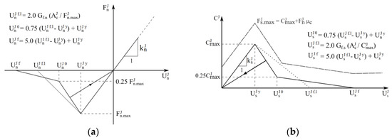
Figure 3.
Constitutive model with bilinear softening: (a) under tension; (b) under shear.
The elastoplastic softening model with joint dilation is based on the theory of plasticity (Figure 4) [34]. This model, which simulates the mechanical behavior of the discontinuities as a function of both the cohesion and the friction angle, is numerically efficient and robust. It was initially proposed for fracture problems analyzed with 3D particle models, in which the particles are represented by finite elements. Failure of this interface model is based on a hyperbolic cracking surface, defined in terms of three parameters: maximum tensile strength (σt), cohesion (c) and tangent of the friction angle (tan φ). The plastic potential is described in terms of another hyperbola which depends on the values of apparent cohesion (cQ) and apparent friction angle (tan φQ), corresponding to a nonassociated formulation.
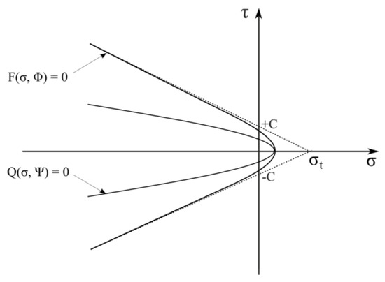
Figure 4.
Softening model based on the theory of plasticity. Hyperbolic cracking surface (F) and plastic potential (Q).
Hyperbolic functions allow a smooth transition from tensile cracking to compression cracking. When the cracking criterion is reached and the crack starts opening or sliding, the cracking surface starts to move and shrink. The corresponding surface evolution is controlled by one single internal variable, Wcr, which is a measure of the work spent during the fracture process. The evolution of the cracking surface is defined in terms of Wcr, the fracture energy for Mode I and the fracture energy for Mode II.
2.2. Hydraulic Model
The interfaces between blocks are filled with water, which moves due to the fluid pressure field, from areas of higher energy to areas of lower energy. The flow through the interfaces is considered laminar and it is assumed that the solid rock matrix is impervious. It should be noted that Louis [24] and Barton et al. [42] showed that the assumption of laminar flow in rock mass dam foundation discontinuities is valid. Flow is modeled by means of the parallel plate model, and the flow rate is expressed by the cubic law [24,43].
The hydraulic model is superimposed on the mechanical model, and thus the mechanical and the hydraulic parts of the proposed interface model are fully compatible. Given the triangular interface element formulation, the hydraulic interfaces are created and each of the hydraulic supernodes (H) represents all the mechanical nodes that possess the same coordinates (Figure 5).
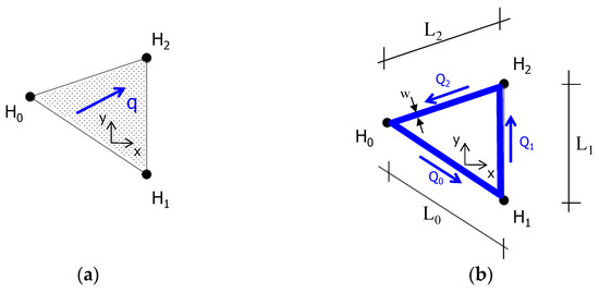
Figure 5.
Hydraulic part of the model: (a) hydraulic interface (adapted from [17]; (b) pseudo seepage channel.
A 2D hydraulic formulation directly based on FE technology [21], as shown in Figure 5a, could have been adopted, but it was decided to adopt an extension of the 2D model presented in [8,35] for the analysis of gravity dams, which is based on a simpler but numerically more robust unidirectional flow formulation, similar to that used in the 2D computational numerical code UDEC [44]. The choice of this model is justified by the fact that in 3D models it is very difficult to make the mechanical and the hydraulic models compatible. This discrete representation of a 2D medium is similar to the approach used in the application of the grid method or of particle discrete elements to simulate continuum media [33]. An advantage of this model is that it can be used directly for the analysis of hydraulic fracturing in particle models [41].
The triangular hydraulic interfaces are defined based on the triangular joint elements, and each hydraulic node (H) also represents the respective adjacent nodes of the mechanical domain that have the same coordinates at the beginning of the numerical simulation. As the numerical hydromechanical analysis evolves, the coordinates of each hydraulic node are given by the average of the coordinates of the group of nodes associated with the mechanical model. Figure 5b shows the hydraulic supernodes and the unidirectional seepage channels, called pseudo seepage channels, located on the edges of the triangular hydraulic interfaces.
The rate of discharge in each seepage channel is given by [45]:
where is the acceleration due to gravity; is the kinematic viscosity of the fluid; is the length of the seepage channel; is the water density; is the dynamic viscosity of the fluid which relates to the kinematic viscosity of the fluid by ; is the pseudo seepage channel permeability; and is the loss of hydraulic head between both ends of the discontinuity, given by:
In the previous equation, and are the pressure and the elevation at the end of the pseudo seepage channel, respectively. The contribution of the dynamic part associated with the seepage velocity is disregarded when the hydraulic gradient is calculated.
In this approach, it is necessary to define the width of the pseudo seepage channels () associated with the edge of each triangular hydraulic interface. In a first stage, this width is calculated in such a way that the total area of the pseudo seepage channels is equal to the area of the hydraulic interface:
where is the length of each edge of the triangular interface and A is the area of the triangular interface element. Thus, a pseudo width must be calculated for each triangular interface element.
For a compressible fluid, variation in the water pressure at the hydraulic node depends on the value of the discharges flowing through the seepage channels that end at that hydraulic node and on the variation in volume associated with the hydraulic node NH:
where is the variation in pressure at the hydraulic node, is the water bulk modulus, is the volume variation associated with the hydraulic node between two consecutive steps and is the timestep used in the hydraulic domain. As long as only steady-state conditions are considered, the volume variation between two consecutive timesteps may be neglected. The water pressure at the following timestep is given by:
Firstly, it is necessary to define the hydraulic aperture () associated with each hydraulic node. The ends of the pseudo seepage channels coincide with the integration points of the mechanical model. As each pseudo seepage channel is associated with a joint element with two integration points at each end, the average aperture of the seepage channel is given as a function of the hydraulic apertures calculated at each end:
The hydraulic aperture associated with each integration point (both ends of the pseudo seepage channels) is obtained as a function of the interface’s normal displacement (mechanical aperture); of the joint normal displacement (); and of three parameters: , and , following the procedure used in the computational code UDEC [44]:
As shown in Figure 6, is the hydraulic aperture when the joint mechanical aperture is zero, which represents the aperture of the discontinuity without normal stresses. When compressive stresses are very high, the hydraulic aperture decreases gradually to a minimum value, , which represents the permeability when the discontinuities are highly compressed. A maximum hydraulic aperture is assumed, , which limits the quantity of water that flows through the discontinuity, therefore limiting joint permeability up to a maximum value.
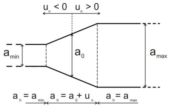
Figure 6.
Hydraulic aperture.
The hydraulic model proposed in this paper allows both confined and unconfined steady-state flows. However, in order to adequately simulate flow in rock masses, where no negative pressures are observed, it is necessary to include in the numerical model two numerical artifices, to ensure that the calculated water pressures are equal or higher than zero. This procedure is described in detail in [8], along with the procedure to ensure that the explicit solution algorithm based on the centered difference scheme is numerically stable.
Modeling of the grout curtain and of the drainage system follows the same assumptions adopted in the 2D hydraulic model [8,35]. Therefore, taking into account the location of the grout curtain, the pseudo seepage channels located in that area are identified, and their permeability is assumed to be about 10 times lower than that of the surrounding rock mass. The location of the drainage system allows the numerical hydraulic nodes to be identified, in which the water pressure is assumed, usually the average water pressure measured in situ.
2.3. Coupled Hydromechanical Model
The seepage–stress coupled model results from the coupling between the mechanical model and the hydraulic model. Figure 7 shows the calculation cycle of the hydromechanical model, which evolves over time through the interaction between both domains, in a simple and sequential coupling. At each timestep, the hydraulic apertures are calculated taking into account the discontinuities’ normal displacements calculated with the mechanical model. Then, the water pressures calculated with the hydraulic model are transferred to the mechanical model as effective stresses and the new mechanical apertures are computed.
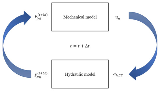
Figure 7.
Hydromechanical calculation cycle.
It is important to note that in the Parmac3D-Fflow model presented here, there is a perfect superimposition between both the mechanical and hydraulic models (the nodal points of the mechanical model are at the same position as the nodal points of the hydraulic model), which makes it easier to define boundary conditions and optimizes information transfer between the two domains.
The ability of the Parmac3D-Fflow model to accurately predict the flow rates and water pressures was verified by carrying out two different hydraulic numerical analyses [46]: (i) flow through a rock mass isotropic medium and (ii) flow through two different permeability formations. For both cases, the numerical results were compared with analytical solutions, presented in [21]. The performance of the coupled hydromechanical model was also assessed considering a system of six impervious blocks and a saturated discontinuity [46]. Results of the application of Parmac3D-Fflow have been recently presented in [47,48].
3. Numerical Hydromechanical Model of an Arch-Gravity Dam
3.1. Model Description
A three-dimensional model of an 83 m high arch-gravity dam and its foundation was created (Figure 8) to carry out hydromechanical analysis and for safety assessment studies. The geometry is based on that of the Ribeiradio dam [47,48], but in this case, the detail of the surface spillway is not included. The dam is simulated by a group of finite element elastic blocks separated by joints, which represent vertical contraction joints. This concrete area is simulated by 1135 hexahedral finite elements, 4840 triangular interface elements to simulate the contraction joints and 19,624 triangular interface elements to consider nonlinear behavior of the dam concrete, with 30,645 nodal points. The foundation is divided into 3884 hexahedral finite elements. Regarding the hydraulic model, it is assumed that dam contraction joints are impervious and seepage takes only place along the seepage channels located at the edges of the triangular joint elements of the dam/foundation joint (Figure 9). This interface has 920 triangular hydraulic interface elements with 21,296 nodal points and 2760 seepage channels.
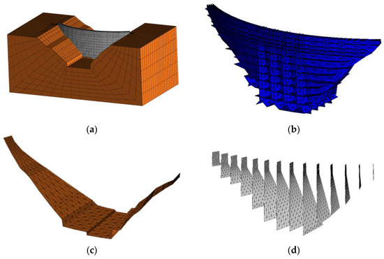
Figure 8.
Global 3D model of an arch-gravity dam and foundation: (a) upstream view of the 20-node finite element mesh; (b) concrete/concrete interface elements; (c) dam/foundation interface elements; (d) dam contraction joints.
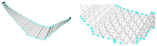
Figure 9.
Triangular hydraulic interfaces and seepage channels at the dam/foundation interface.
Figure 9 also shows the hydraulic boundary conditions: black hydraulic nodes are impervious areas, and light blue hydraulic nodes are those where the hydrostatic pressure is imposed, corresponding to the hydrostatic pressure on the upstream and downstream faces of the dam. In this study, the grout curtain is not simulated, and analysis is carried out assuming firstly that the drainage system is operating properly (OD) and after, in a very unfavorable situation, that it is clogged and thus nonoperational (NOD). It is assumed that the drainage boreholes are drilled from a foundation gallery which is aligned with the insertion of the dam in the foundation, as shown in Figure 10, and at the bottom of the valley, the drainage system is located around 6.0 m from the heel of the dam.
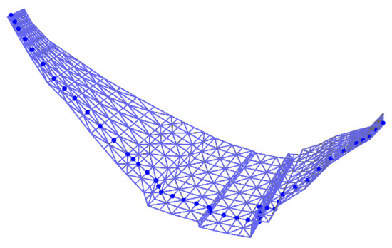
Figure 10.
Position of the drainage system at the dam/foundation interface (highlighted in dark blue).
3.2. Material Properties
Table 1 shows the mechanical properties of both the dam and the foundation, and Table 2 shows the mechanical properties of the contraction joints (concrete/concrete joints) and of the dam/foundation interface (concrete/rock), based on data presented by Dong et al. [31]. The other parameters required to define the constitutive models SM1 and SM2 are chosen taking into account relations usually considered for such materials [31,34]. In the concrete/concrete interfaces, the normal stiffness (kn) is assumed to be 60.6 Gpa/m and the shear stiffness (ks) is equal to 24.24 Gpa/m. At the dam/foundation interface, it is assumed that kn = 128.8 Gpa/m and kt = 51.52 Gpa/m. At the joint elements representing the dam contraction joints, a Mohr–Coulomb constitutive model with zero tensile strength and zero cohesion is adopted. Assigning a zero tensile strength allows the interfaces to open in areas where tensile stresses occur. With a shear strength defined by zero cohesion and an assumed friction angle, only friction prevents the interfaces from sliding.

Table 1.
Material properties of the volume elements [31].
Table 2.
Material properties of the joint elements.
Acceleration due to gravity is 10 m/s2. Regarding the hydraulic properties of the seepage channels, it is assumed that the initial hydraulic aperture of discontinuities, a0, is equal to 0.0834 mm; the minimum aperture, amin, is equal to a0/3; and the maximum aperture, amax, is equal to 5 × amin. In this study, a multiplicative factor of λ = 2 was applied to the seepage channels´ pseudo width so as to obtain discharges close to those which would be obtained with a 2D hydraulic formulation [49].
3.3. Sequence of Analysis
The sequence of analysis includes: (i) calculation of in situ stresses due to the weight of the rock mass, (ii) consideration of dam weight and (iii) application of hydrostatic loading on the upstream face of the dam and of the uplift pressure at the base of the dam. It is assumed that the water is at its maximum level in the reservoir and at the ground level downstream from the dam. Once the results of the coupled hydromechanical analysis are obtained, sliding stability analysis is carried out, either using the strength reduction method or considering an amplification of the water pressures resulting from an increase in the reservoir level.
3.4. Results Analysis
3.4.1. Uplift Pressures
Figure 11 shows the field of hydraulic head at the dam/foundation interface calculated with the hydromechanical model, assuming either a nonoperational or operational drainage system. The hydraulic head (also known as total head, piezometric head, hydraulic potential or simply head) is the sum of the elevation head (distance from some arbitrary datum) and the pressure head (fluid pressure divided by the unit weight of the fluid). In this case, the elevation head is equal to 25 m.
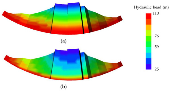
Figure 11.
Hydraulic head at the dam/foundation interface: (a) nonoperational drainage system; (b) operational drainage system.
Figure 12 shows the distribution of uplift pressures, which vary from 0.83 Mpa at the heel of the dam, given from the upstream water level, to zero at the toe of the dam, where the water is assumed to be at the ground level. Analysis of Figure 11 and Figure 12 leads to the conclusion that coherent results are obtained with Parmac3D-Fflow, both with nonoperational and operational drainage systems.
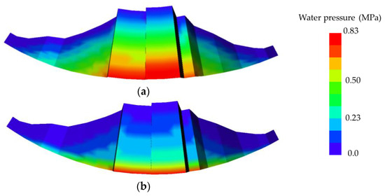
Figure 12.
Uplift pressures at the dam/foundation interface: (a) nonoperational drainage system; (b) operational drainage system.
Figure 13 shows four different lines in the upstream/downstream direction at the dam/foundation interface along which the variation in uplift pressures is represented (Figure 14). These figures show that coherent results are obtained assuming both a nonoperational and an operational drainage system, and that at the bottom of the valley, the hydromechanical analysis yields higher uplift pressures than those given by a linear distribution of water pressures between the reservoir and the tailwater, usually assumed in the limit equilibrium analysis.
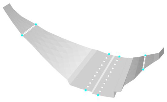
Figure 13.
Lines in the upstream/downstream direction at the dam/foundation interface along which water pressures are represented (see Figure 14).
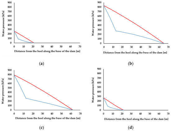
Figure 14.
Water pressures along lines in the upstream/downstream direction at the dam/foundation interface, assuming a drainage system operational (blue line) or nonoperational (red line): (a) left bank; (b) bottom of the valley, on the left bank; (c) bottom of the valley, on the right bank; (d) right bank.
3.4.2. Quantity of Water That Flows through the Dam/Foundation Interface
Analysis of numerical discharges shows that in this numerical simulation the amount of water that flows through the dam/foundation interface in the hydromechanical analysis when the drainage system is assumed to be nonoperational is 9.78 × 10⁻⁵ m3/s, which corresponds to 5.868 L/min. This increases by around 369%, up to 3.61 × 10⁻⁴ m3/s (21.66 L/min), in the case of an operational drainage system, of which 3.24 × 10⁻⁴ m3/s (19.44 L/min) is water collected at the drainage gallery.
It should be noted that the numerical quantity of water that flows through the dam/foundation system depends on both the mechanical and hydraulic properties of the discontinuities. Therefore, simulation of the hydromechanical behavior of a real dam requires continuous validation and calibration against field data.
3.4.3. Stresses
Figure 15 shows the vertical stresses at the upstream and downstream faces of the dam, calculated assuming a nonoperational drainage system, due to the combined effect of dead weight, hydrostatic pressure and uplift pressure. It should be noted that, as the dam has a triangular cross-section, stresses due only to the dead weight are considerably higher at the upstream face close to the dam/foundation interface than those at the downstream face. The application of the hydrostatic loading on the upstream face of the dam and of the uplift pressure at the base of the dam leads to a decrease in compressive stresses at the upstream face and to an increase in such stresses at the downstream face of the dam. This figure also shows that even in this latter case, the maximum compressive stresses are located at the upstream face, close to the dam/foundation interface.
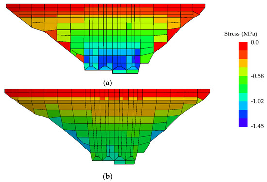
Figure 15.
Vertical stresses, calculated assuming a nonoperational drainage system, due to the combined effect of dead weight, hydrostatic pressure and uplift pressure: (a) upstream face of the dam; (b) downstream face of the dam.
Figure 16 shows the horizontal stresses at the upstream and downstream faces of the dam, calculated assuming a nonoperational drainage system, due to the combined effect of dead weight, hydrostatic pressure and uplift pressure. Maximum compressive stresses are obtained at the central area of the upstream face of the dam and close to both the right and left banks, at approximately mid-height of the dam. These stress fields are justified by the horizontal curvature of the dam.
Figure 16.
Horizontal stresses, calculated assuming a nonoperational drainage system, due to the simultaneous effect of dead weight, hydrostatic pressure and uplift pressure: (a) upstream face of the dam; (b) downstream face of the dam.
4. Sliding Stability Analysis
The failure scenario of sliding along the foundation joint is analyzed using either the strength reduction method or the method of amplification of the hydrostatic pressure. Damage to the concrete, evolution of dam displacements at the crest of the central cantilever and safety factors are analyzed in detail.
4.1. Strength Reduction Method
Safety evaluation is carried out by performing a sequence of analysis in which the strength properties of the discontinuities are progressively reduced. This procedure has the advantage of enabling the evaluation of displacement indicators during the process of strength reduction. In the study presented here, analysis of dam foundation stability began by neglecting the contribution of both cohesion and tensile strength in the foundation joint but keeping a friction angle of 45° (tan ϕ = 1.0). The friction angle of the foundation joint was then gradually reduced (the reduction coefficient was applied to the tangent of the friction angle).
Figure 17 shows the dam failure mode, assuming an operational drainage system. This figure shows that the failure mechanism includes sliding towards downstream and the simultaneous rotation of the dam blocks towards downstream close to the left bank, which leads to the opening of joints close to the valley bottom. Figure 18 shows damage within the dam concrete (in blue) for the bilinear softening constitutive model SM1 at the concrete/concrete joints within the dam concrete. A Mohr–Coulomb failure with zero tensile strength and cohesion is assumed at the contraction joints.
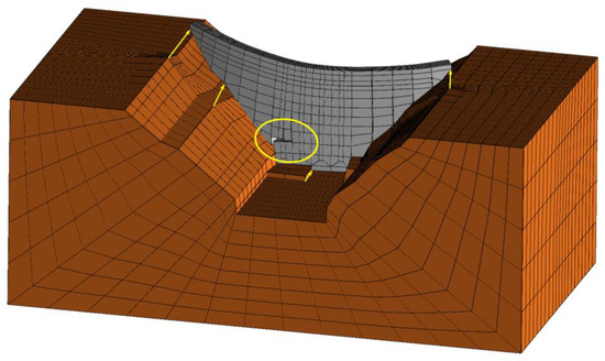
Figure 17.
Failure mode using the strength reduction method, assuming an operational drainage system (displacement field magnified 500 times).
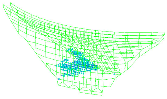
Figure 18.
Cracking pattern within the concrete assuming the bilinear softening model SM1 (open cracks shown in blue and closed cracks shown in green).
Figure 19 shows a comparison of the damage field obtained at failure within the dam concrete, assuming the bilinear softening model (SM1) and the elastoplastic model (SM2) at the concrete/concrete interfaces (with the exception of the contraction joints). It can be seen that, as expected, damage occurs in the same area, although the percentage of damaged interfaces is slightly higher when model SM2 is assumed.
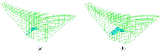
Figure 19.
Cracking pattern within the concrete with an operational drainage system assuming at the concrete/concrete interface: (a) bilinear softening model (SM1); (b) elastoplastic model (SM2).
Figure 20 shows the variation in displacements at the top of the dam central block during the process of reduction in the tangent of the friction angle (these values include displacements due to dead weight, hydrostatic pressure and uplift pressures), assuming either a nonoperational drainage system (NOD) or an operational drainage system (OD). In this figure, for ease of analysis, friction angles in the x-axis are shown in reverse order. The angle of friction was reduced down to 5.19°. Assuming a nonoperational drainage system (Figure 20a) and the bilinear softening model (SM1), failure was reached for a friction angle of 7.21°, while with the elastic model and the elastoplastic model (SM2), the dam was still stable for a friction angle of 5.19°. Figure 20b shows that with an operational drainage system, the minimum value of 5.19° was achieved with the three different models. Due to the particular geometry of this dam, the structure is at equilibrium even when the friction angle is reduced down to zero.
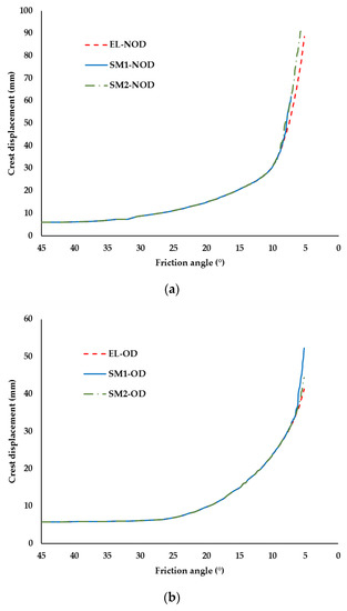
Figure 20.
Variation in displacements at the top of the central cantilever during the process of strength reduction: (a) nonoperational drainage system (NOD); (b) operational drainage system (OP).
Figure 20 shows that with an operational drainage system, dam displacements remain almost the same until the friction angle is reduced down to 25.46°, which corresponds to a safety factor F = 2.1. From this point onwards, a gradual increase in displacements is observed, and this increase becomes steeper for lower friction angles. Assuming a nonoperational drainage system, displacements have a moderate increase until the friction angle is reduced down to 32.01°, which corresponds to a safety factor F = 1.6, and a more visible increase for higher values of the reduction factor. The approach presented here of defining the safety factor F based on the friction angle for which a change in the structural behavior is identified is commonly used at the design stage and allows overcoming the limitations of assuming linear elastic behavior. It should be highlighted that in some cases the change in structural behavior associated with cracking within the dam concrete prevents the numerical model from achieving convergence.
4.2. Amplification of Hydraulic Pressure
Additional analysis is carried out, which consists of applying a gradually increasing water pressure, simulating the scenario of dam overtopping. An increase of 1.0 m is considered for each cycle. The failure indicator is again the horizontal crest displacement. Two different hypotheses are considered: (i) hydromechanical analysis is not carried out during the process of increasing the reservoir level, and thus uplift pressures remain constant during this process, or (ii) hydromechanical analysis is carried out during the process of increasing the reservoir level. In both cases, only friction prevents contraction joints from sliding and the analysis is carried out assuming:
- SM1 within the dam concrete and a cohesive brittle contact model at the dam/foundation interface (zero tensile strength and cohesion);
- SM1 within the dam concrete and at the dam/foundation interface;
- SM2 within the dam concrete and at the dam/foundation interface.
4.2.1. Nonoperational Drainage System
Figure 21 shows the dam deformation at failure when it is assumed that the drainage system is clogged. It can be seen that the failure mechanism involves the dam displacement towards downstream, with a simultaneous rotation of the dam blocks towards downstream close to the left bank combined with a global rotation around the downstream face.
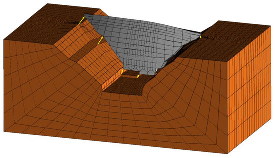
Figure 21.
Failure mode, assuming a nonoperational drainage system and carrying out hydromechanical analysis (displacement field magnified 2000 times).
Figure 22 shows the cracking pattern within the dam concrete, which is very localized, and at the dam/foundation interface, where all contacts are opened. In this case, a very similar cracking pattern is obtained with both SM1 and SM2 models and performing or not a hydromechanical analysis during the increase in the reservoir level.
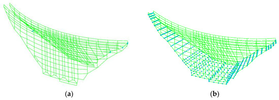
Figure 22.
Cracking pattern with a nonoperational drainage system: (a) at the concrete/concrete interfaces; (b) at the dam/foundation interface.
Figure 23 shows the variation in crest displacement during the process of increasing the reservoir level for the different models and keeping the uplift pressures constant or carrying out a hydromechanical analysis. The results presented highlight the relevance of taking into account the increase in uplift pressures. In fact, when the uplift pressures are kept constant (UC), higher water levels are possible when compared with the model in which the uplift pressures are recalculated according to the current water level (C). In the former case, a safety factor of around 2.0 is obtained, and in the latter case, this value is around 1.6.
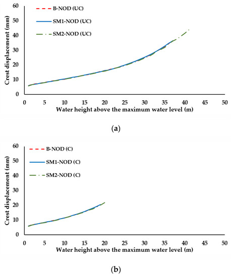
Figure 23.
Variation in displacements at the top of the central cantilever, during the process of amplification of water pressure, with a nonoperational drainage system: (a) constant uplift pressures; (b) hydromechanical analysis.
4.2.2. Operational Drainage System
Figure 24 shows the dam deformation at failure when it is assumed that the drainage system is operating properly. As in the case presented in the previous section, it can be seen that the failure mechanism is very similar to that obtained with a nonoperational drainage system. However, with an operational drainage system, the maximum water height is higher due to the lower uplift pressure.
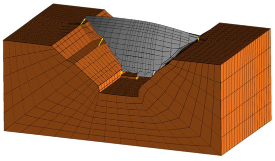
Figure 24.
Failure mode, assuming an operational drainage system and carrying out hydromechanical analysis (displacement field magnified 2000 times).
Figure 25 shows the cracking pattern when the uplift pressures remain constant within the dam concrete and at the dam/foundation interface. Within the dam concrete, only a few cracks develop. In this case, due to drainage, uplift pressures are significantly lower. Therefore, at the bottom of the valley, cracking is only observed close to the upstream edge. The same cracking pattern is obtained with both SM1 and SM2 and performing or not a hydromechanical analysis during the increase in the reservoir level.
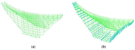
Figure 25.
Cracking pattern with an operational drainage system: (a) at the concrete/concrete interfaces; (b) at the dam/foundation interface.
Figure 26 shows a comparison between the cracking pattern at the dam/foundation interface when hydromechanical analysis is carried out and uplift pressures are recalculated according to the current water level, for the two different softening models. In the bottom of the valley, the cracking patterns are slightly different, and more extensive cracks occur when SM1 is used.
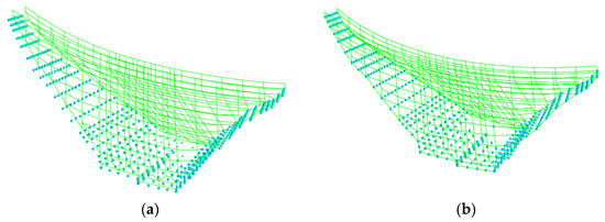
Figure 26.
Cracking pattern at the concrete/concrete interface with an operational drainage system: (a) SM1; (b) SM2.
Figure 27 shows the variation in crest displacement during the process of increasing the reservoir level for the different models and keeping the uplift pressures constant or carrying out hydromechanical analysis.
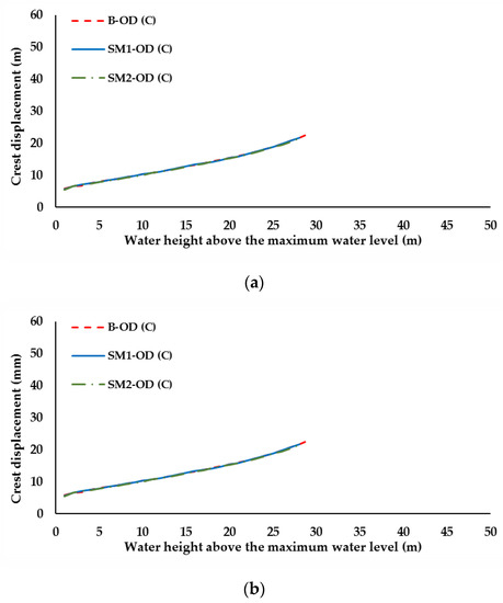
Figure 27.
Variation in displacements at the top of the central cantilever, during the process of amplification of water pressure, with an operational drainage system: (a) constant uplift pressures; (b) hydromechanical analysis.
4.2.3. Safety Factors
Table 3 shows the maximum water heights above the maximum reservoir level (H) which ensure safety against sliding and the corresponding safety factors (F) for the four different models. This table shows, as expected, that safety factors are higher when an operational drainage system is assumed and that safety factors are lower when the hydromechanical analysis is carried out during the process of increasing the water level. Results obtained when model SM1 is assigned within the dam concrete and at the dam/foundation interface are very close to those obtained adopting a brittle contact model at the dam/foundation interface, although a higher safety factor is obtained for the model OD (C). The cases in which model SM2 is assigned within the dam concrete and at the dam/foundation interface lead to higher safety factors, with the exception of model OD (C). For this loading scenario, the adoption of a brittle contact model at the dam/foundation interface leads to a slightly higher safety factor (F = 1.89), showing that adopting a brittle model does not always guarantee that the analysis is on the safe side.
Table 3.
Maximum water heights above the maximum reservoir level which ensure safety against sliding (H), and corresponding safety factors (F).
5. Discussion and Conclusions
A 3D discontinuum hydromechanical model based on a small displacement finite element formulation is presented for the coupled hydromechanical analysis of concrete dam foundations and applied to the analysis of the safety of a dam/foundation system against dam base sliding. Mechanical properties of the dam concrete and of the concrete/concrete and concrete/rock joints are based on experimental data. Numerical results are presented and analyzed regarding uplift pressures, quantity of water that flows through conductive discontinuities and stresses at the dam body. Results show a coherent pattern. Sliding safety is evaluated using the process of progressive reduction in strength characteristics of the dam foundation interface to very low values or assuming an exceptional rise in the reservoir level. Two different situations are analyzed, with and without a drainage curtain.
The results presented show that the hydromechanical model is able to predict uplift pressures in complex valley 3D geometries. The proposed hydraulic model following a discrete seepage unidirectional flow approach is shown to be robust, and the adopted numerical artifices ensure that the calculated water pressures are equal to or higher than zero. Therefore, the model is able to analyze seepage problems that involve the particular boundary condition of a seepage face, where pressure is zero and thus the hydraulic head equals the elevation head.
The sliding stability analysis carried out shows that the strength reduction method may not lead to a conservative safety factor. In fact, the approach based on the amplification of the hydrostatic pressure may lead to lower safety factors when the uplift pressure is also increased, which can be straightforwardly carried out with the proposed hydromechanical model.
The stability analysis also shows that nonlinear behavior of the dam concrete body should also be taken into account since higher (erroneous) safety factors are obtained when elastic behavior of the dam body is assumed.
In the dam/foundation interface, softening models should be adopted for the joint elements as their behavior is closer to that observed experimentally in concrete/rock interfaces tested under shear and tensile loading. The results presented show that for a sliding stability analysis using a simple bilinear directional model with simple coupling, it is possible to obtain similar results to those obtained with an elastoplastic model including dilation. It is also shown that similar safety factors are obtained if a brittle model is adopted for the dam/foundation interface. This is due to the fact that the mode I fracture energy of the concrete/rock interface obtained experimentally is significantly lower than the usual value adopted for concrete. Sensitive studies must be carried out in order to assess if a similar behavior is obtained for higher values of fracture energy in mode I.
The results clearly show the potential of the developed hydromechanical tool. Further work is currently underway in order to apply this numerical tool to more complex meshes including the main faults and sets of rock joints within the dam foundation, in addition to the discontinuities simulated in the model presented herein. This development in the numerical model, along with the knowledge gained from the numerical analysis presented in this paper, is essential to develop an effective application to a real case of an operating dam and allow comparison of numerical results with monitoring data for different conditions, such as displacements, stresses, recorded discharges and water pressures. Work is also being carried out so as to attempt to apply a hydromechanical coupled analysis during the process of amplification of the hydraulic pressures, in which there is a continuous updating of the built-up uplift pressures, in consequence of the progressive aperture and crack propagation at the dam/foundation interface due to the loads applied.
Author Contributions
Conceptualization, M.L.B.F., N.M.A. and N.A.S.L.; methodology, M.L.B.F., N.M.A. and N.A.S.L.; software, N.M.A. and S.O.; validation, M.L.B.F., N.M.A. and J.R.d.A.; writing—original draft preparation, M.L.B.F. and N.M.A.; writing—review and editing, M.L.B.F., N.M.A., N.A.S.L., J.R.d.A. and S.O.; supervision, M.L.B.F. and N.M.A.; project administration, M.L.B.F. and N.M.A.; All authors have read and agreed to the published version of the manuscript.
Funding
This research received no external funding.
Institutional Review Board Statement
Not applicable.
Informed Consent Statement
Not applicable.
Data Availability Statement
Not applicable.
Acknowledgments
The study presented here is part of the ongoing project “DAMFA- Cutting-edge solutions for sustainable assessment of concrete dam foundations” carried out jointly by LNEC and FCT/UNL, with the main purpose of developing a numerical multiphysics integrated tool for the sustainable assessment of concrete dam foundations, taking into account the interaction between mechanical, hydraulic and thermal behaviors.
Conflicts of Interest
The authors declare no conflict of interest.
References
- Bustamante, L.; Radisic, A. Structural design and RCC zoning in Ralco dam. In Proceedings of the 22nd International Congress on Large Dams, Barcelona, Spain, 18–23 June 2006; ICOLD: Paris, France, 2006; Volume 1, pp. 33–45. [Google Scholar]
- Lombardi, G. 3-D analysis of gravity dams. Int. J. Hydropower Dams 2007, 14, 98–102. [Google Scholar]
- Lemos, J.V. Discontinuum models for dam foundation failure analysis. Keynote Lecture. In Proceedings of the 12th International Congress on Rock Mechanics, Beijing, China, 16–21 October 2011. [Google Scholar]
- Farinha, M.L.B.; Lemos, J.V.; Maranha das Neves, E. Numerical modelling of borehole water-inflow tests in the foundation of the Alqueva arch dam. Can. Geotech. J. 2011, 48, 72–88. [Google Scholar] [CrossRef] [Green Version]
- Farinha, M.L.B.; Lemos, J.V.; Maranha das Neves, E. Analysis of foundation sliding of an arch dam considering the hydromechanical behaviour. Front. Struct. Civ. Eng. 2012, 6, 35–43. [Google Scholar] [CrossRef] [Green Version]
- Barla, G.; Bonini, M.; Cammarata, G. Stress ans seepage analyses for a gravity dam on a jointed granitic rock mass. In Proceedings of the 1st International UDEC/3DEC Symposium: Numerical Modeling of Discre Materials in Geotechnical Engineering, Civil Engineering and Earth Sciences, Bochum, Germany, 29 September–1 October 2004; pp. 263–268. [Google Scholar]
- Gimenes, E.; Fernández, G. Hydromechanical analysis of flow behavior in concrete gravity dam foundations. Can. Geotech. J. 2006, 43, 244–259. [Google Scholar] [CrossRef]
- Farinha, M.L.B.; Azevedo, N.M.; Candeias, M. Small displacement coupled analysis of concrete gravity dam foundations: Static and dynamic conditions. Rock Mech. Rock Eng. 2017, 50, 439–464. [Google Scholar] [CrossRef]
- Bretas, E.; Lemos, J.V.; Lourenço, P. Hydromechanical analysis of mansonry gravity dams and their foundations. Rock Mech. Rock Eng. 2013, 46, 327–339. [Google Scholar] [CrossRef] [Green Version]
- Noorishad, J.; Ayatollahi, M.S.; Witherspoon, P.A. A finite-element method for coupled stress and fluid flow analysis in fractured rock masses. Int. J. Rock Mech. Min. Sci. Geomech. Abstr. 1982, 19, 185–193. [Google Scholar] [CrossRef]
- Gell, K. Influence of Seepage in the Underground to the Calculation of Stresses and Deformations of Arch Dams. Ph.D. Thesis, RWTH, Aachen, Germany, 1983. (In German). [Google Scholar]
- Wittke, W.; Gell, K. Wechselwirkung zwischen Staumauer und Untergrund. Wasserwirtschaft 1984, 74, 137–141. [Google Scholar]
- Gell, K.; Wittke, W. A new design concept for arch dams taking into account seepage forces. Rock Mech. Rock Eng. 1986, 19, 187–204. [Google Scholar] [CrossRef]
- Erban, P.; Gell, K. Consideration of the interaction between dam and bedrock in a coupled mechanic-hydraulic FE-program. Rock Mech. Rock Eng. 1988, 21, 99–117. [Google Scholar] [CrossRef]
- Gomes de Mendonça, T. Three-Dimensional Finite Element Model for the Analysis of the Hydromechanical Behaviour of Concrete Dam Foundations; Report 158/99; LNEC: Lisboa, Portugal, 1989; pp. 1–67. (In Portuguese) [Google Scholar]
- Sun, Y. A Three-Dimensional Model for Transient Fluid Flow through Deformable Fractured Porous Media. Ph.D. Thesis, University of Minnesota, Minneapolis, MN, USA, 1994. [Google Scholar]
- Damjanac, B. A Three-Dimensional Numerical Model of Water Flow in a Fractured Rock Mass. Ph.D. Thesis, University of Minnesota, Minneapolis, MN, USA, 1996. [Google Scholar]
- Rutqvist, J.; Stephansson, O. The role of hydromechanical coupling in fractured rock engineering. Hydrogeol. J. 2003, 11, 7–40. [Google Scholar] [CrossRef] [Green Version]
- Shukla, R.; Ranjith, P.G.; Choi, S.K.; Haque, A. A novel testing apparatus for hydromechanical investigation of rocks: Geo-sequestration of carbon dioxide. Rock Mech. Rock Eng. 2012, 45, 1073–1085. [Google Scholar] [CrossRef]
- Yan, C.; Zheng, H.; Sun, G.; Ge, X. Combined finite-discrete element method for simulation of hydraulic fracturing. Rock Mech. Rock Eng. 2016, 49, 1389–1410. [Google Scholar] [CrossRef]
- Yan, C.; Zheng, H. FDEM-flow3D: A 3D hydro-mechanical coupled model considering the pore seepage of rock matrix for simulating three-dimensional hydraulic fracturing. Comput. Geotech. 2017, 81, 212–228. [Google Scholar] [CrossRef]
- Yan, C.; Jiao, Y.-Y.; Zheng, H. A fully coupled three-dimensional hydro-mechanical finite discrete element approach with real porous seepage for simulating 3D hydraulic fracturing. Comput. Geotech. 2018, 96, 73–89. [Google Scholar] [CrossRef]
- Londe, P.; Sabarly, F. La distribution des perméabilités dans la foundation des barrages voûtes en fonction du champ de contrainte. In Proceedings of the 1st International Congress on Rock Mechanics, Lisbon, Portugal, 25 September–1 October 1966; Volume II, pp. 517–522. [Google Scholar]
- Louis, C. A Study of Groundwater Flow in Jointed Rock and Its Influence on the Stability of Rock Masses. Ph.D. Thesis, University of Karlsruhe, English Translation, Imperial College Rock Mechanics Research Report Nº10, London, UK, 1969. (In German). [Google Scholar]
- Louis, C.; Maini, Y.N. Determination of in situ hydraulic parameters in jointed rock. In Proceedings of the 2nd International Congress on Rock Mechanics, Belgrade, Serbia, 21–26 September 1970; Volume I, pp. 235–245. [Google Scholar]
- Cornet, F.H.; Li, L.; Hulin, J.P.; Ippolito, I.; Kurowski, P. The hydromechanical behavior of a fracture: An in situ experimental case study. Int. J. Rock Mech. Min. Sci. 2003, 40, 1257–1270. [Google Scholar] [CrossRef]
- Sadeghiyeh, S.M.; Hashemi, M.; Ajalloeian, R. Comparison of permeability and groutability of Ostur dam site rock mass for grout curtain design. Rock Mech. Rock Eng. 2013, 46, 341–357. [Google Scholar] [CrossRef]
- Rastegarnia, A.; Sohrabibidar, A.; Bagheri, V.; Razifard, M.; Zolfaghari, A. Assessment of relationship between grouted values and calculated values in the Bazoft dam site. Geotech. Geol. Eng. 2017, 35, 1299–1310. [Google Scholar] [CrossRef]
- European Club of ICOLD. Sliding Safety of Existing Gravity Dams—Final Report; Report of the European Working Group: Rome, Italy, 2004. [Google Scholar]
- Liu, X.; Zhu, W.; Zhang, P.; Li, L. Failure in rock with intersecting rough joints under uniaxial compression. Int. J. Rock Mech. Min. Sci. 2021, 146, 104832. [Google Scholar] [CrossRef]
- Dong, W.; Wu, Z.; Zhou, X. Fracture mechanisms of rock-concrete interface: Experimental and numerical. J. Eng. Mech. 2016, 142, 04016040. [Google Scholar] [CrossRef] [Green Version]
- Dong, W.; Yang, D.; Zhang, B.; Wu, Z. Rock-concrete interfacial crack propagation under mixed mode I-II fracture. J. Eng. Mech. 2018, 144, 04018039. [Google Scholar] [CrossRef]
- Azevedo, N.M. A Rigid Particle Discrete Element Model for the Fracture Analysis of Plain and Reinforced Concrete. Ph.D. Thesis, Heriot-Watt University, Scotland, UK, 2003. [Google Scholar]
- Caballero, A.; Willam, K.J.; Carol, I. Consistent tangent formulation for 3D interface modeling of cracking/fracture in quasi-brittle materials. Comput. Methods Appl. Mech. Eng. 2008, 197, 2804–2822. [Google Scholar] [CrossRef]
- Azevedo, N.M.; Farinha, M.L.B. A hydromechanical model for the analysis of concrete gravity dam foundations. Geotecnia 2015, 133, 5–33. (In Portuguese) [Google Scholar] [CrossRef]
- Underwood, P. Dynamic relaxation. In Computational Methods for Transient Analysis; North Holland: New York, NY, USA, 1983. [Google Scholar]
- Lemos, J.V.; Cundall, P. Earthquake analysis of concrete gravity dams on jointed rock foundations. In Distinct Element Modelling in Geomechanics; Oxford and IBH Publishing: New Delhi, India, 1999; pp. 117–143. [Google Scholar]
- Goodman, R.; Taylor, R.; Brekke, T. A model for the mechanics of jointed rock. J. Soil Mech. Found. Div. (ASCE) 1968, 94, 637–659. [Google Scholar] [CrossRef]
- Hohberg, J. A Joint Element for the Nonlinear Dynamic Analysis of Arch Dams. Ph.D. Thesis, Institute of Structural Engineering, ETH, Zurich, Switzerland, 1992. [Google Scholar]
- Andjelkovic, V.; Pavlovic, N.; Lazarevic, Z.; Nedovic, V. Modelling of shear characteristics at the concrete-rock mass interface. Int. J. Rock Mech. Min. Sci. 2015, 76, 222–236. [Google Scholar] [CrossRef]
- Azevedo, N.M.; Candeias, M.; Gouveia, F. A Rigid Particle Model for Rock Fracture Following the Voronoi Tessellation of the Grain Structure: Formulation and Validation. Rock Mech. Rock Eng. 2015, 48, 535–557. [Google Scholar] [CrossRef]
- Barton, N.; Bandis, S.; Bakhtar, K. Strength, deformation and conductivity coupling of rock joints. Int. J. Rock Mech. Min. Sci. GeoMech. Abstr. 1985, 22, 121–140. [Google Scholar] [CrossRef]
- Snow, D.T. A Parallel Plate Model of Fractured Permeable Media. Ph.D. Thesis, University of California, Berkeley, CA, USA, 1965. [Google Scholar]
- Itasca UDEC—Universal Distinct Element Code; Version 4.0; Itasca Consulting Group: Minneapolis, MN, USA, 2004.
- Bear, J. Dynamics of Fluids in Porous Media; Dover Publications, Inc.: New York, NY, USA, 1988. [Google Scholar]
- Farinha, M.L.B.; Azevedo, N.M.; Leitão, N.S.; Castilho, E.; Câmara, R. 3D coupled hydromechanical analysis of dam foundations. In Proceedings of the 9th European Conference on Numerical Methods in Geotechnical Engineering (NUMGE 2018), Porto, Portugal, 25–27 June 2018. [Google Scholar]
- Freitas, G.; Farinha, M.L.B.; Azevedo, N.M.; Almeida, J.R.; Sá, M.; Leitão, N.S. Discontinuous hydromechanical modelling of concrete dam foundations. In Proceedings of the Fourth International Dam World Conference, Lisboa, Portugal, 21–25 September 2020; Volume 1. [Google Scholar]
- Azevedo, N.M.; Farinha, M.L.B.; Freitas, G.; Almeida, J.R. Safety evaluation of an arch-gravity dam based on a small displacement hydromechanical coupled model. In Lecture Notes in Civil Engineering. Challenges and Innovations in Geomechanics; IACMAG 2021; Barla, M., Di Donna, A., Sterpi, D., Eds.; Springer: Cham, Switzerland, 2021; Volume 126. [Google Scholar] [CrossRef]
- Azevedo, N.M.; Farinha, M.L.B.; Sá, M.; Almeida, J.R. Discontinuum models in three-dimensional hydromechanical analysis of the behavior of concrete dam foundations. Geotecnia 2021, 151, 5–32. (In Portuguese) [Google Scholar] [CrossRef]
Publisher’s Note: MDPI stays neutral with regard to jurisdictional claims in published maps and institutional affiliations. |
© 2022 by the authors. Licensee MDPI, Basel, Switzerland. This article is an open access article distributed under the terms and conditions of the Creative Commons Attribution (CC BY) license (https://creativecommons.org/licenses/by/4.0/).