
Numerical Study of the Behavior of Back-to-Back Mechanically Stabilized Earth Walls


Abstract
:1. Introduction
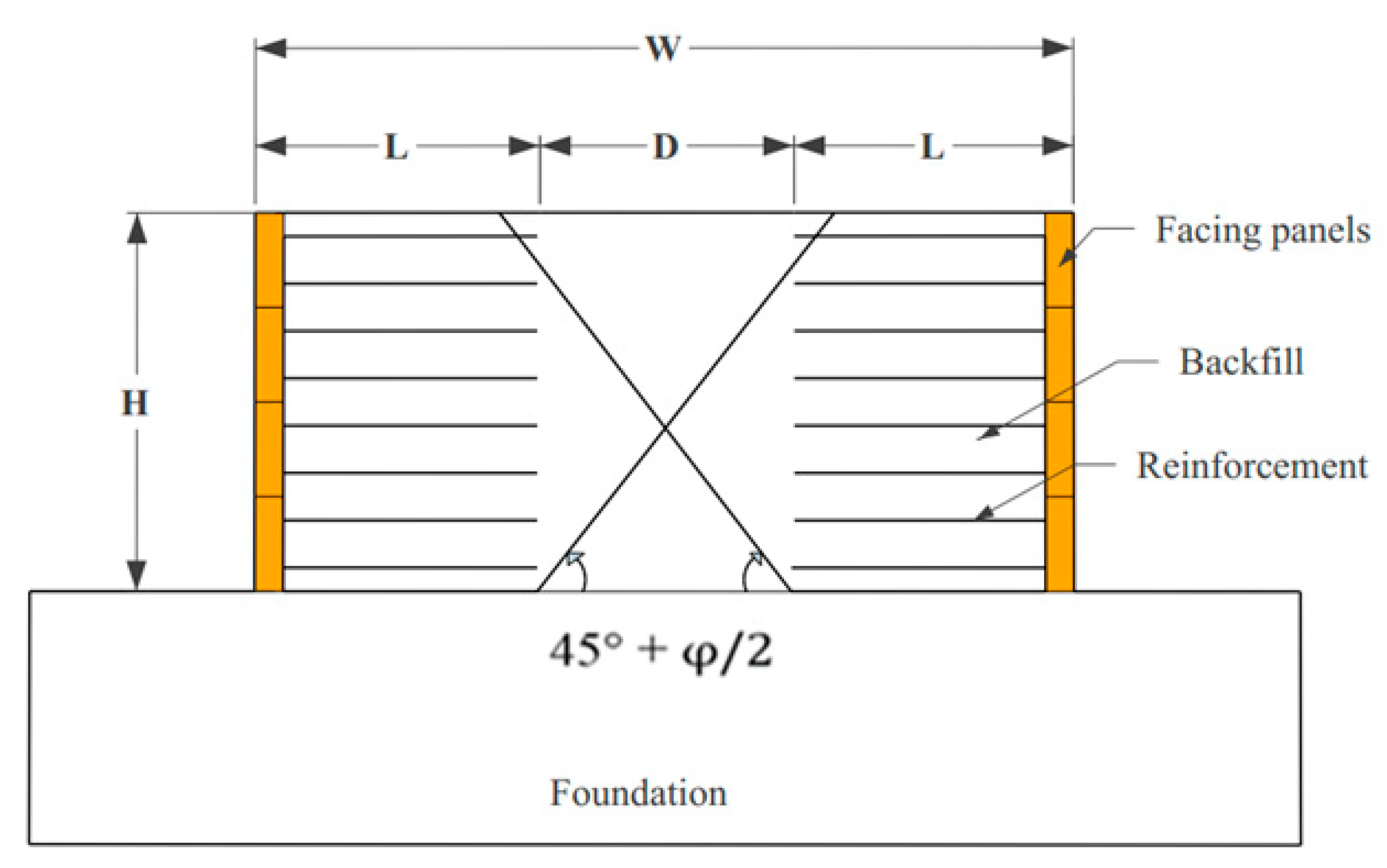
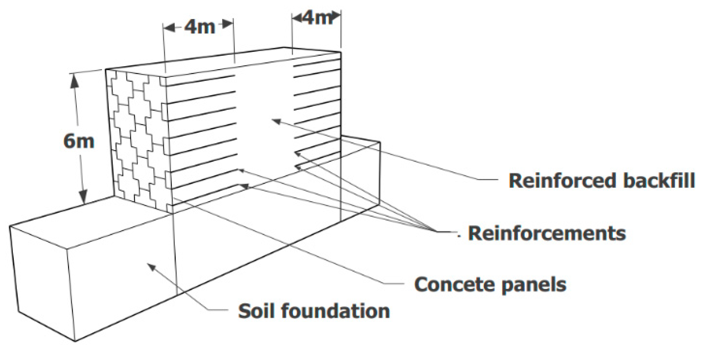
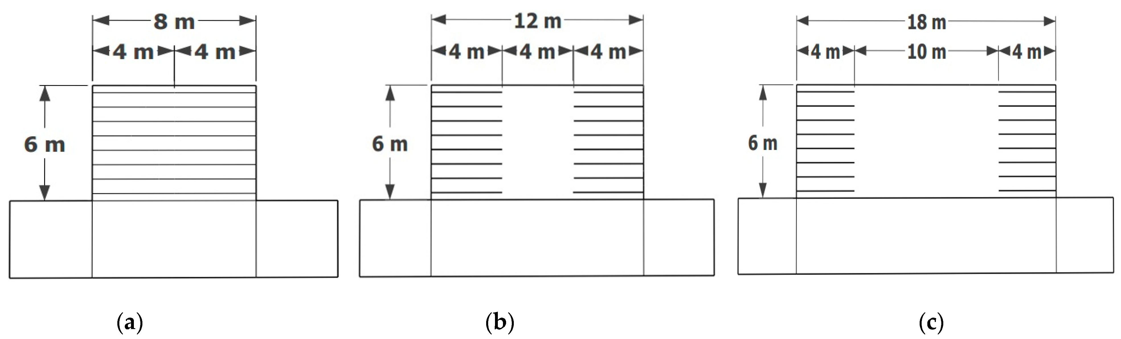
2. Studied Case
2.1. Geometry of the Wall
2.2. Soils
2.3. Concrete Face and Doil Foundation
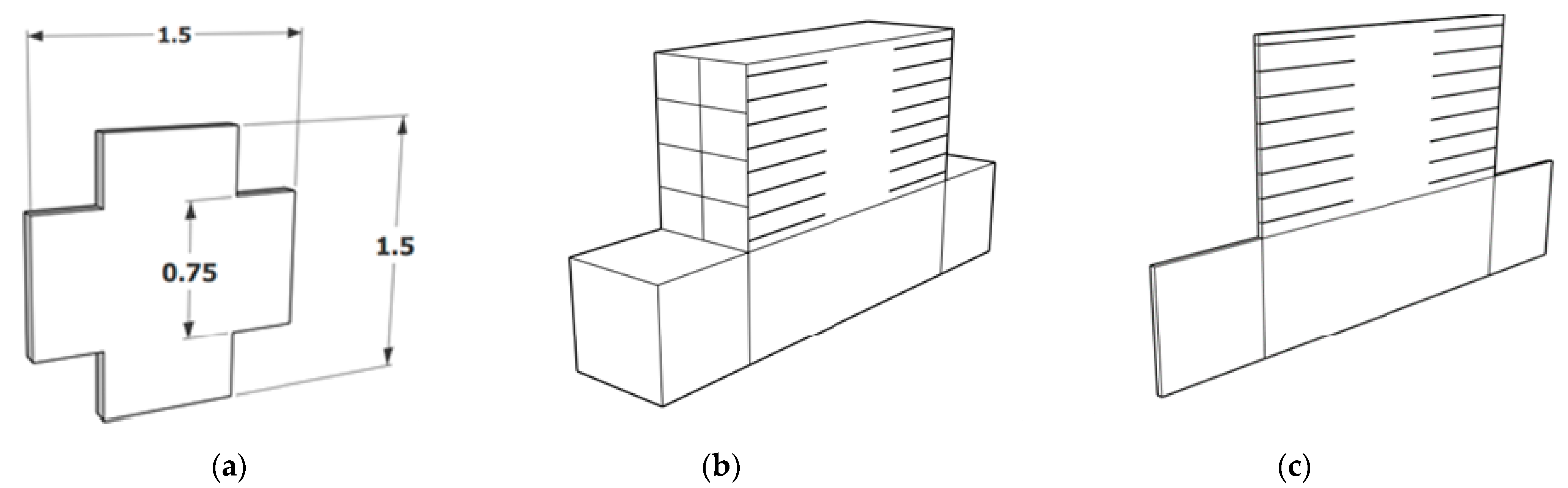
2.4. Concrete Panel/Soil Interface
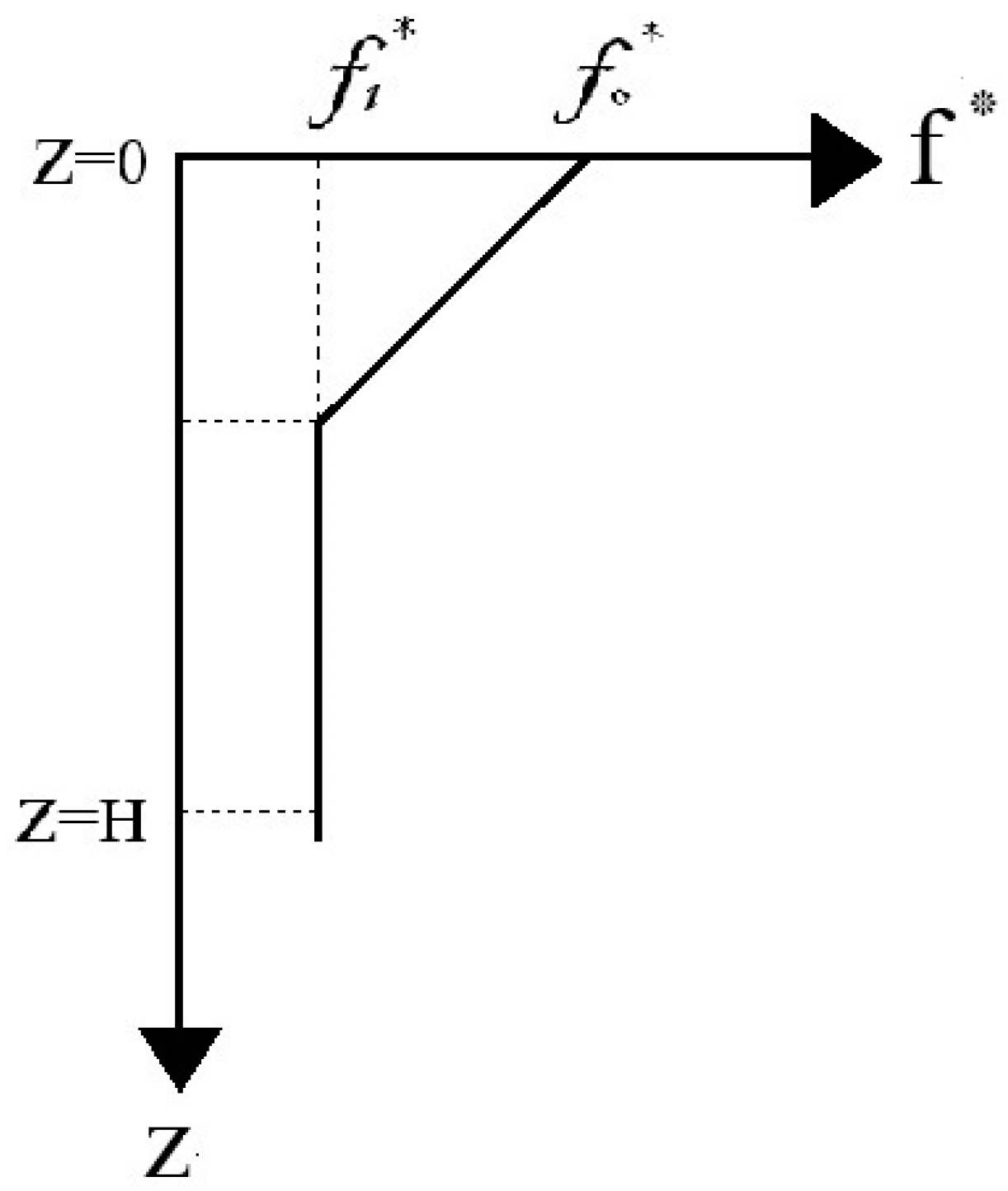
2.5. Reinforcements
- f*: Apparent friction coefficient/
- : Maximum shear stresses exerted by reinforcements.
- : Initial vertical stress applied on strips.
- kb: Shear stiffness at the soil strip interface.
- : Maximum tensile force on the strip.
- : Strip length.
- : Relative soil/strip displacement at the total mobilization of the strip in pullout tests for a wall of 1 m in width.
2.6. Comparison Criterion
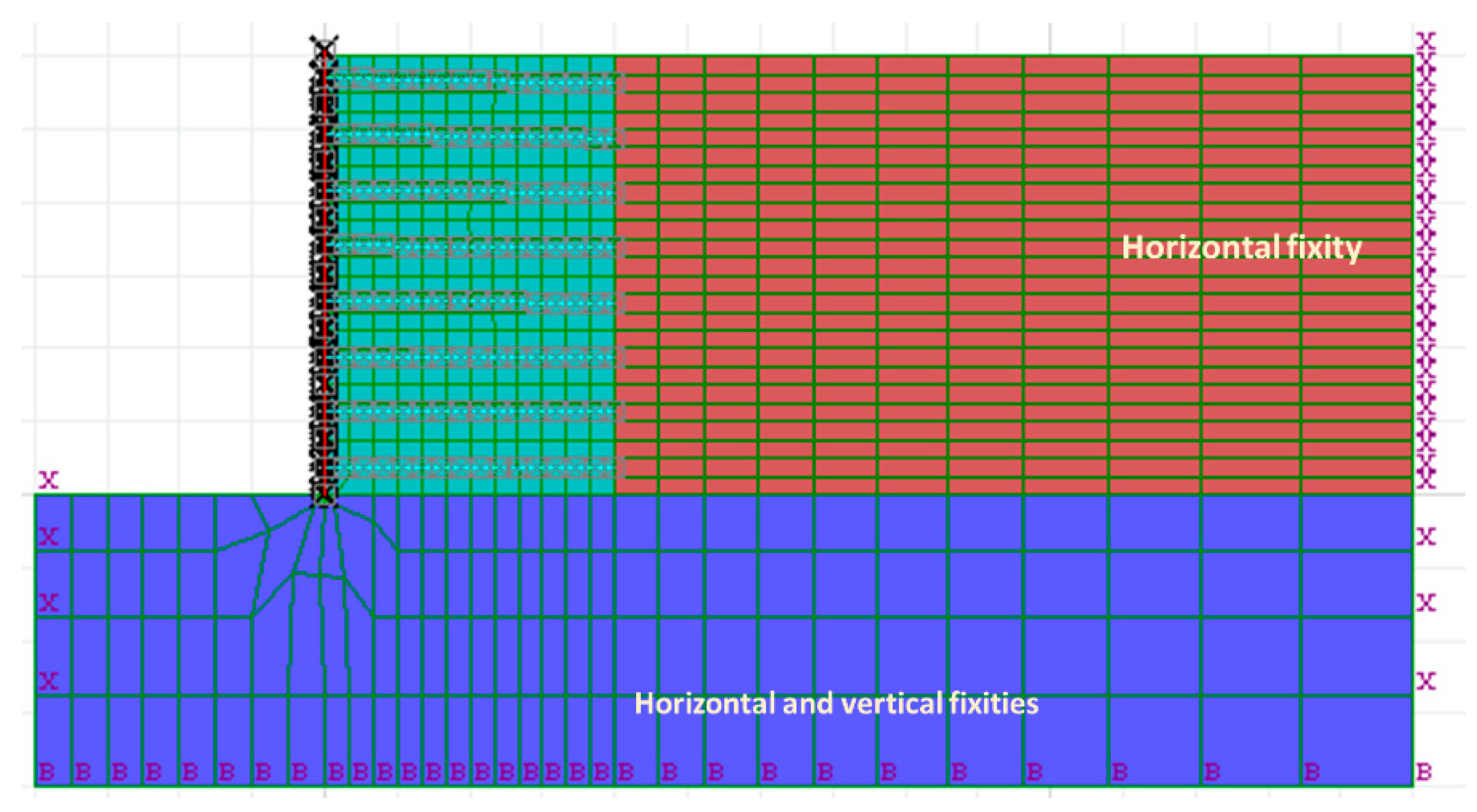
3. Numerical Modeling
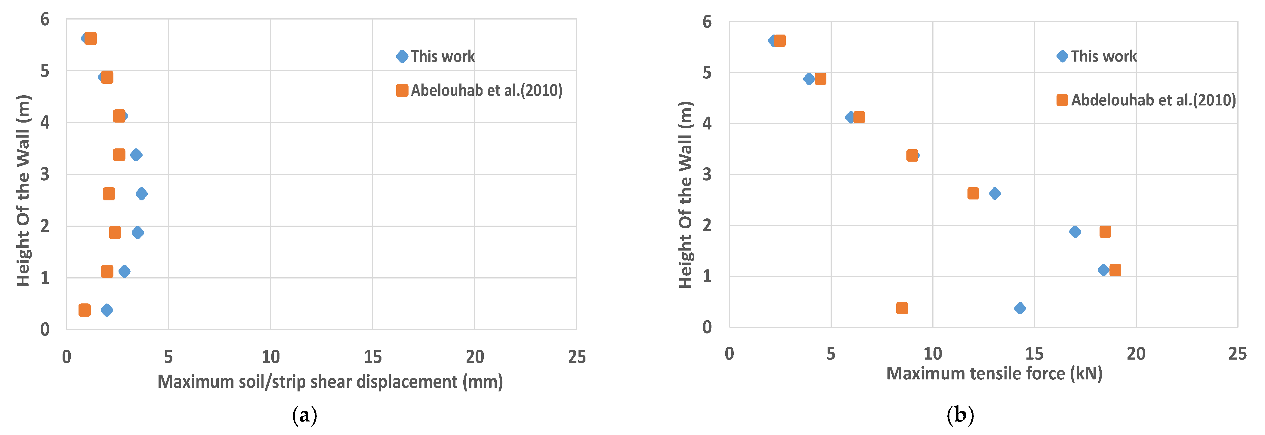
3.1. Reference Model
3.2. Parametric Analysis
3.2.1. Influence of the Width to Height Ratio (W/H)
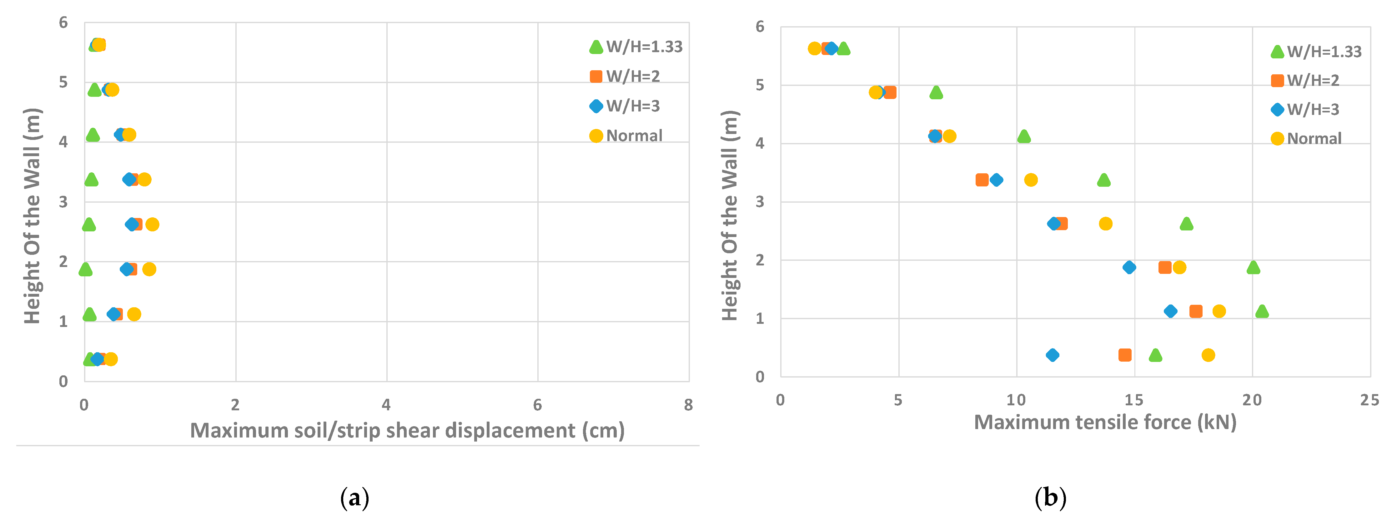
Soil/Strip Shear Displacement
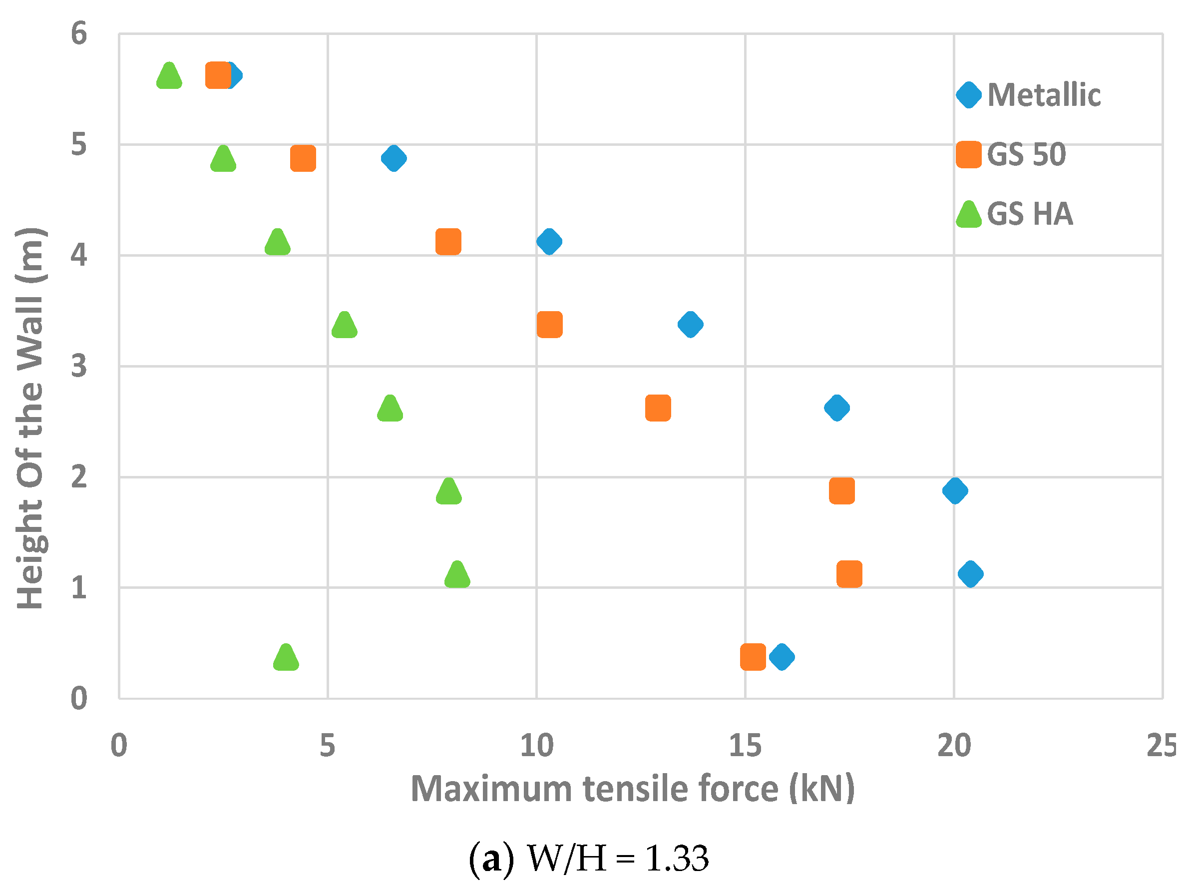
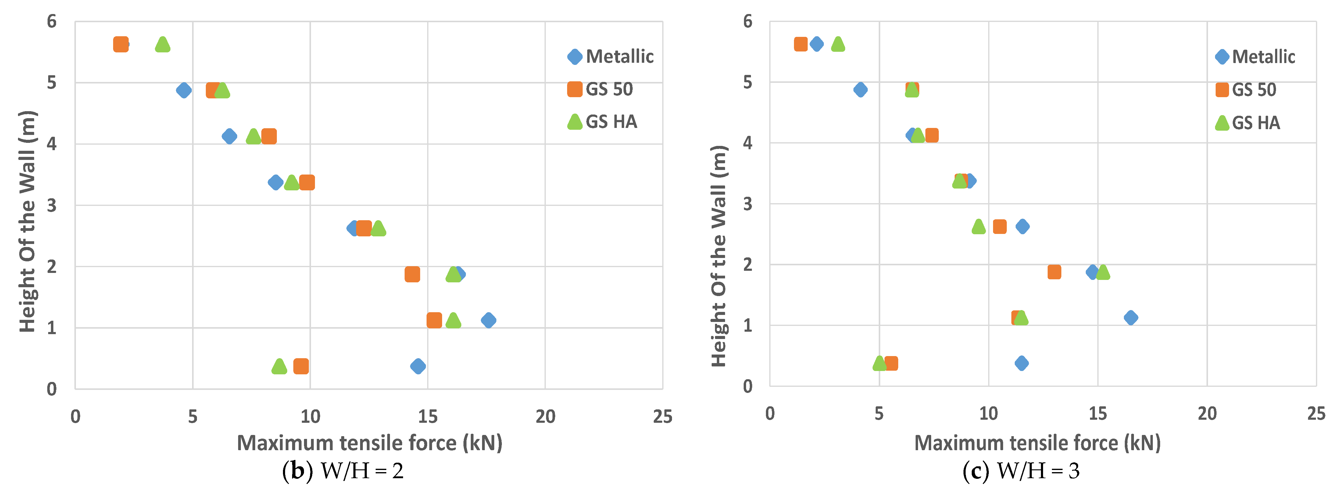
Tensile Force
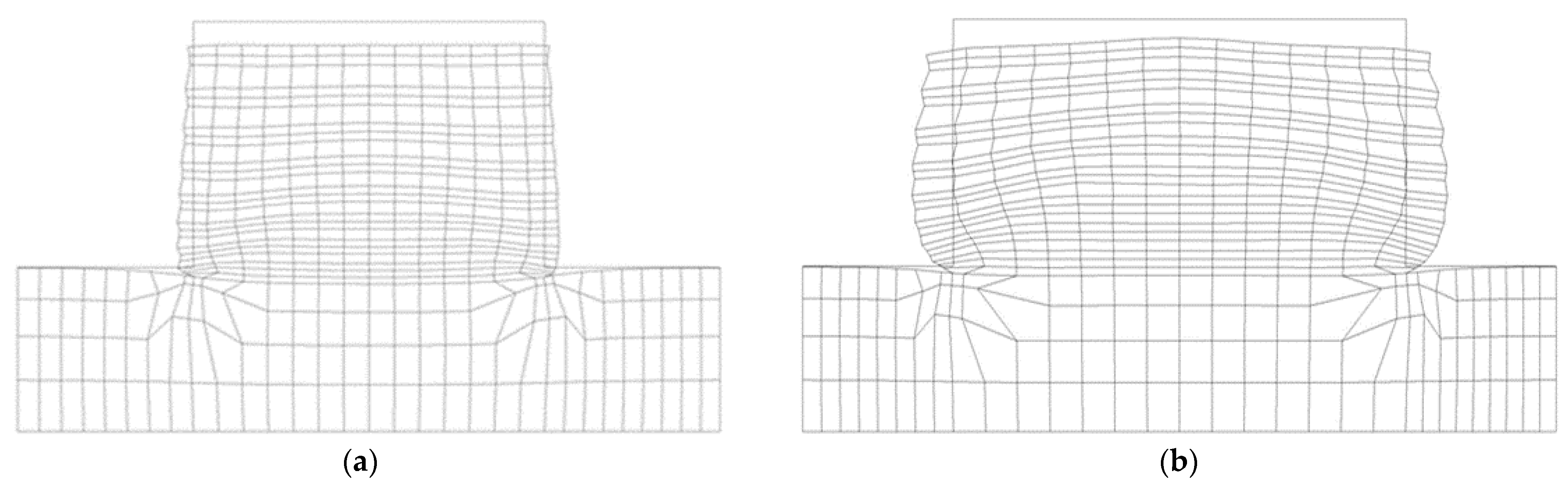
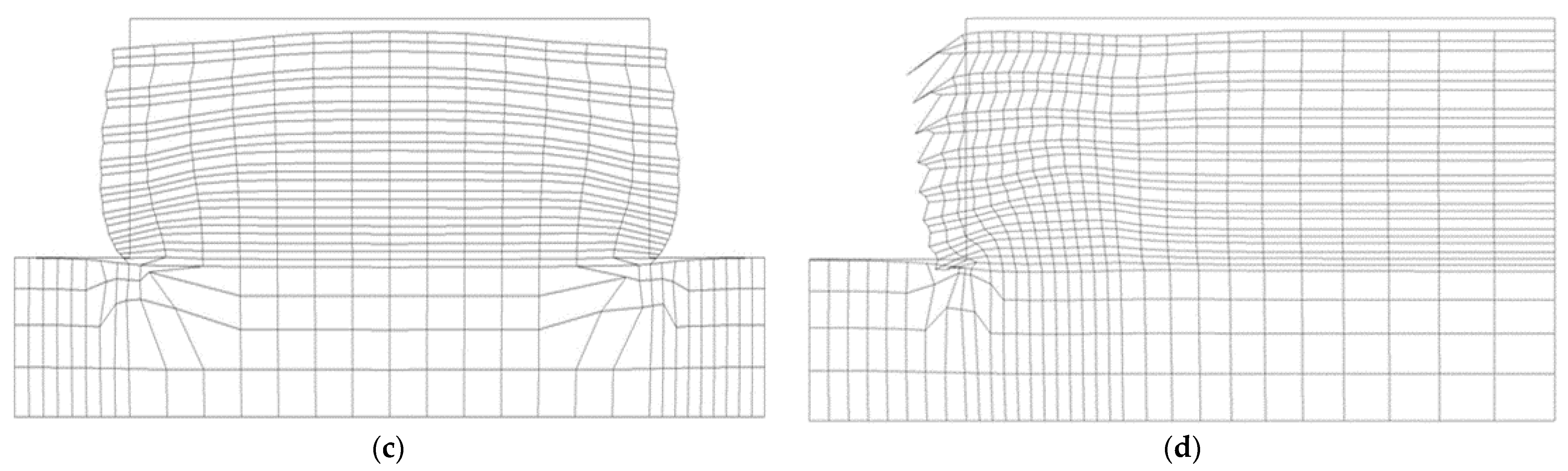
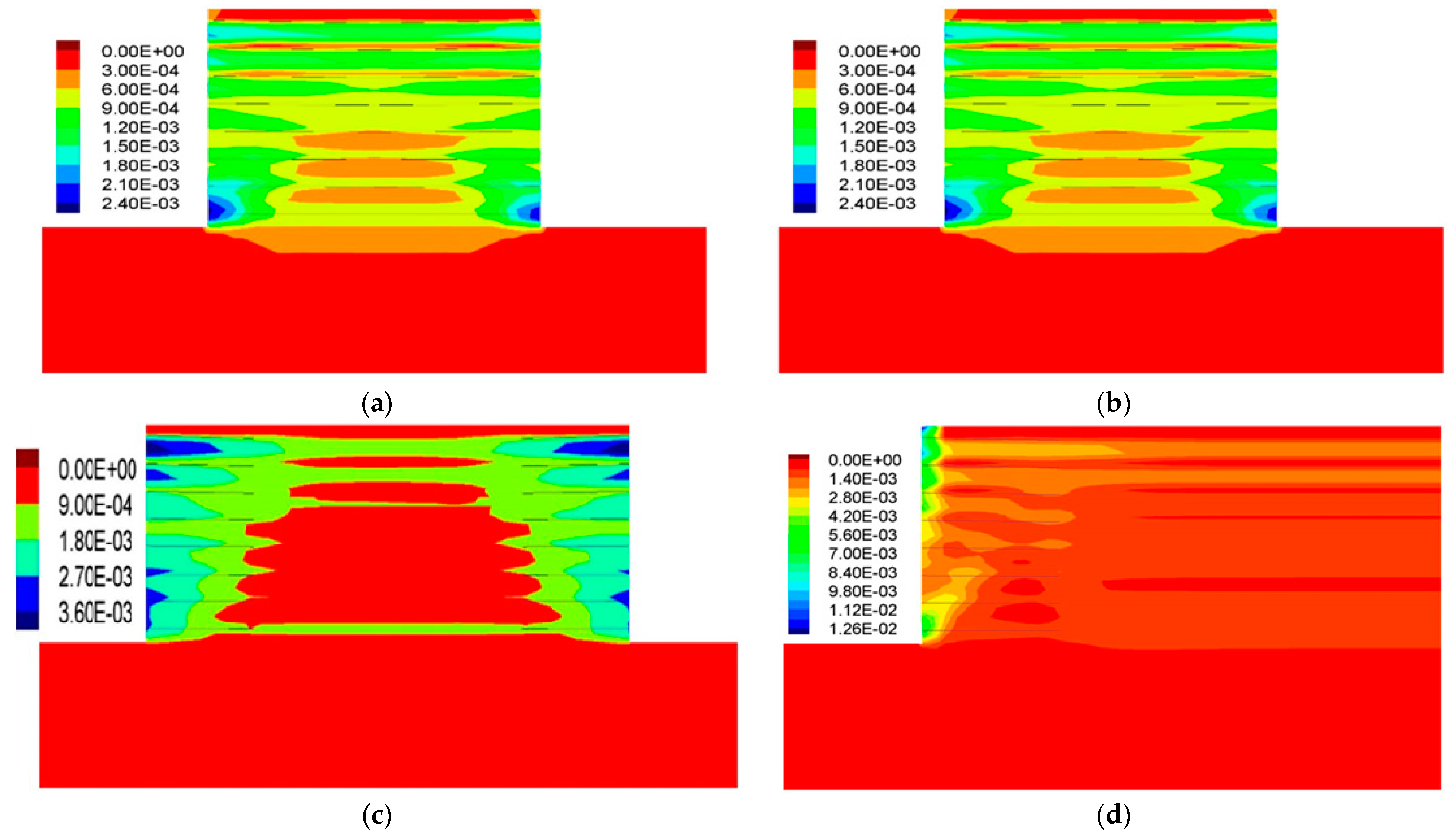
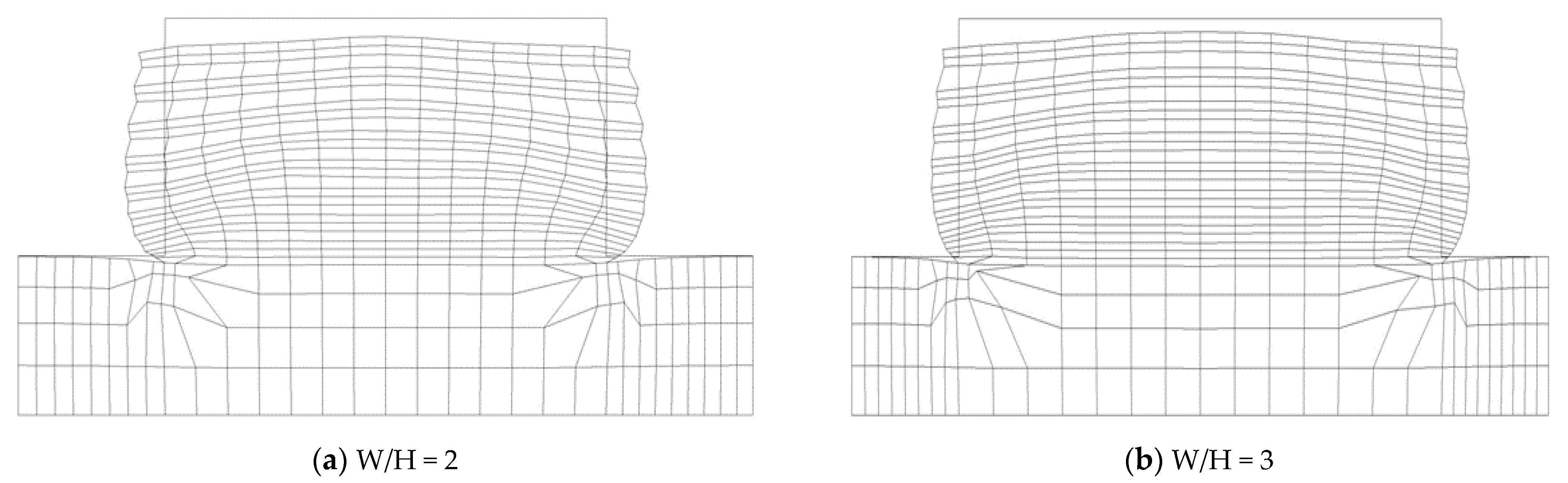
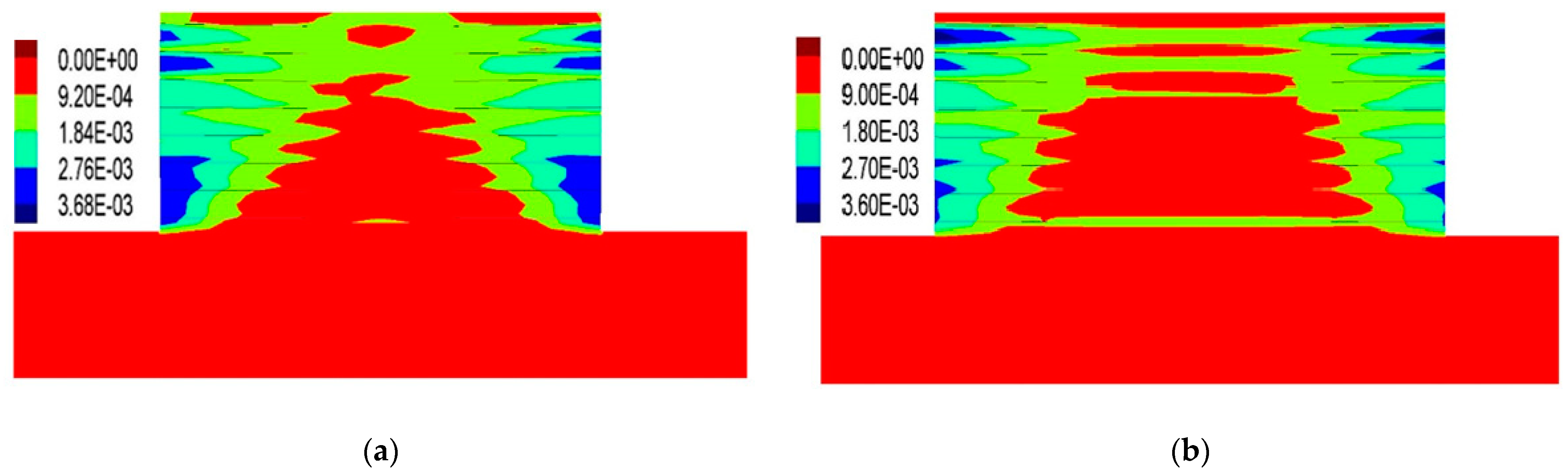
Ultimate Limit State of Back-to-Back Reinforced Walls
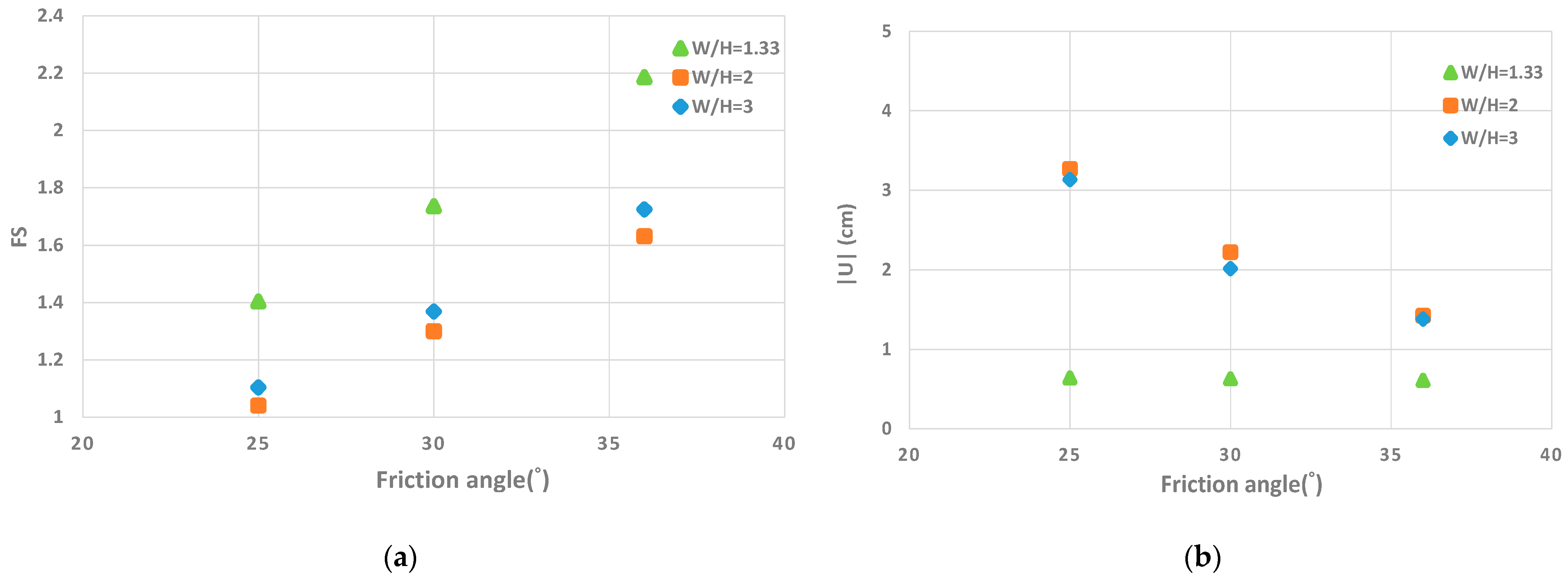
3.2.2. Influence of the Friction Angle (φ)
3.2.3. Influence of the Strip Type
3.3. Comparison of the Back-to-Back Wall with the Reference Case (Single-Sided Wall)
3.3.1. Metallic Strips
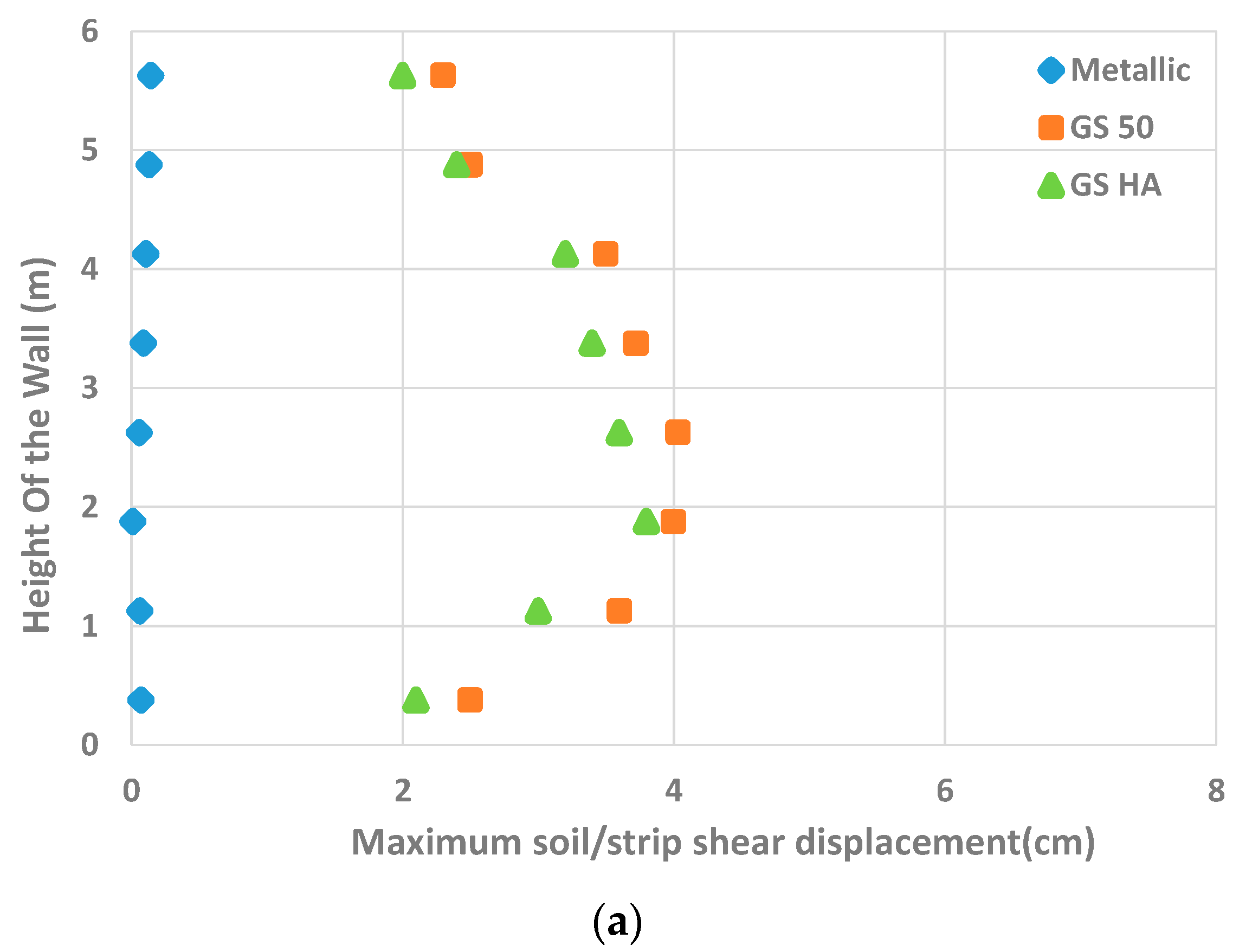
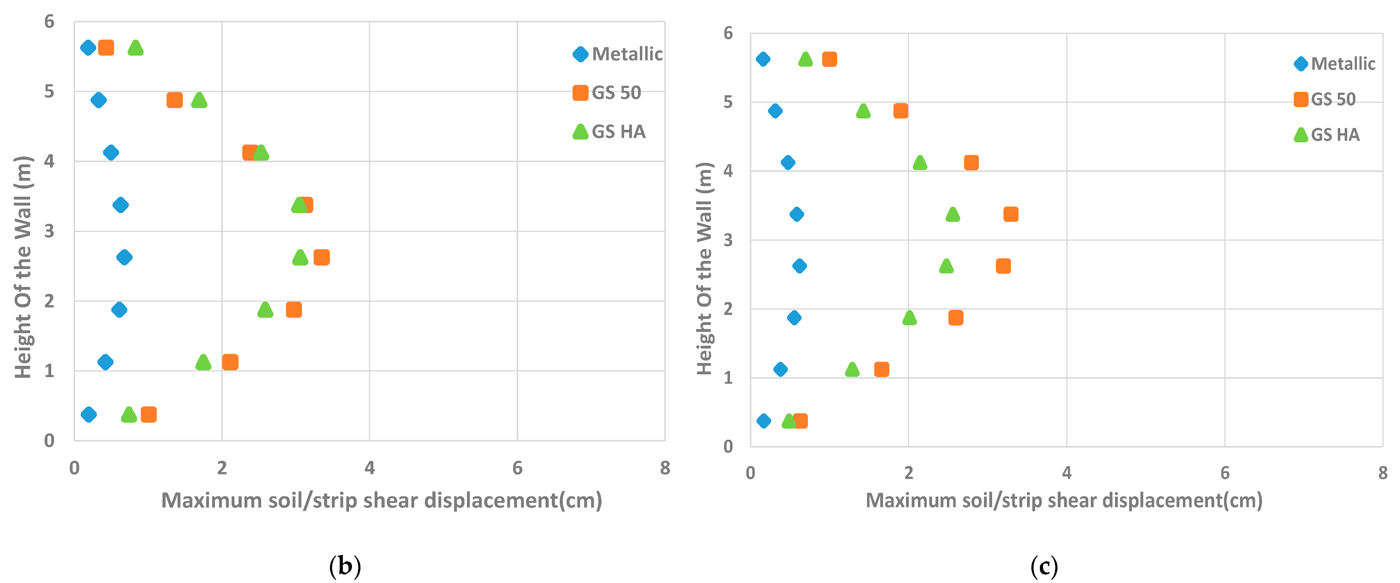
Soil/Strip Shear Displacement
Tensile Force
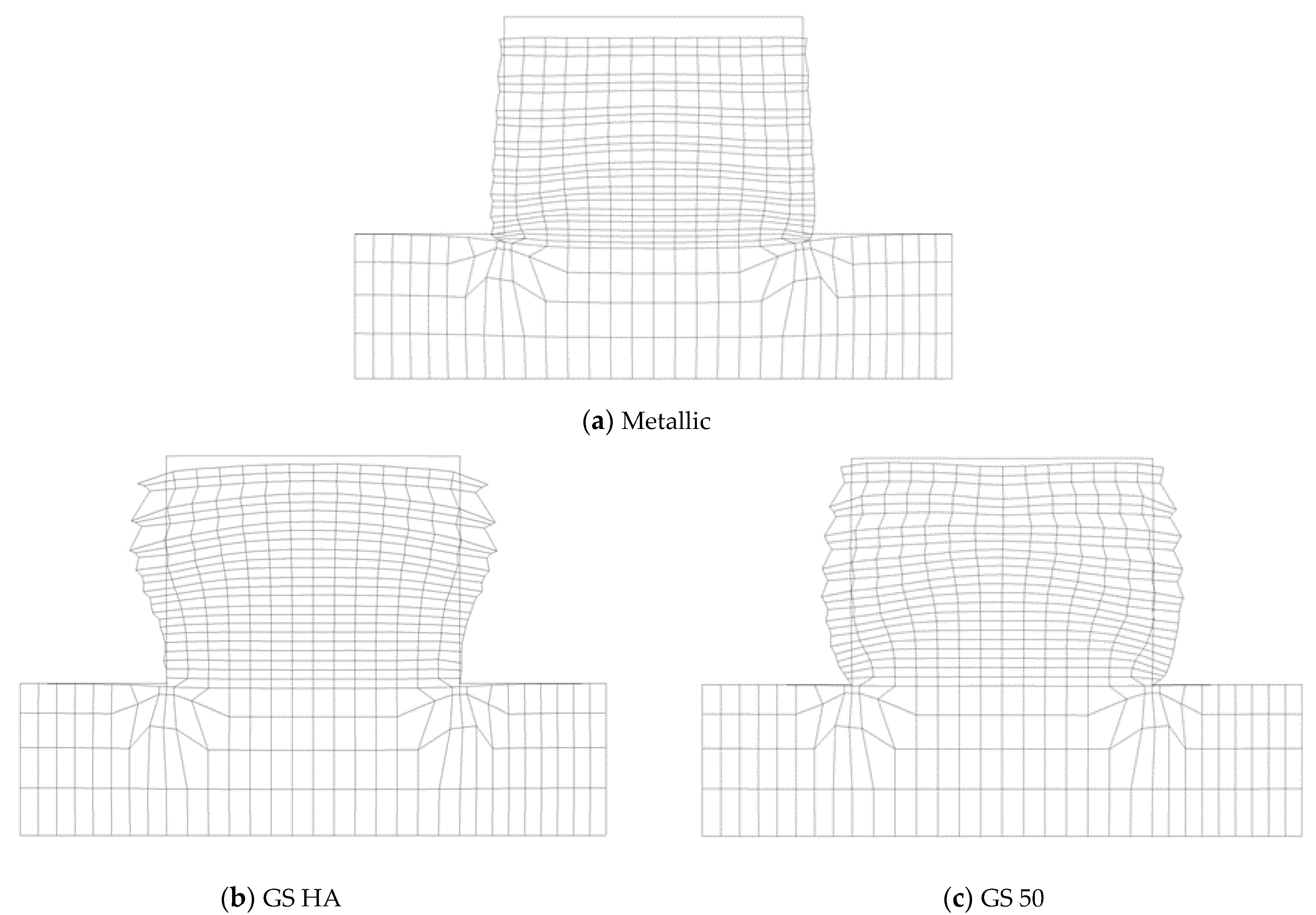
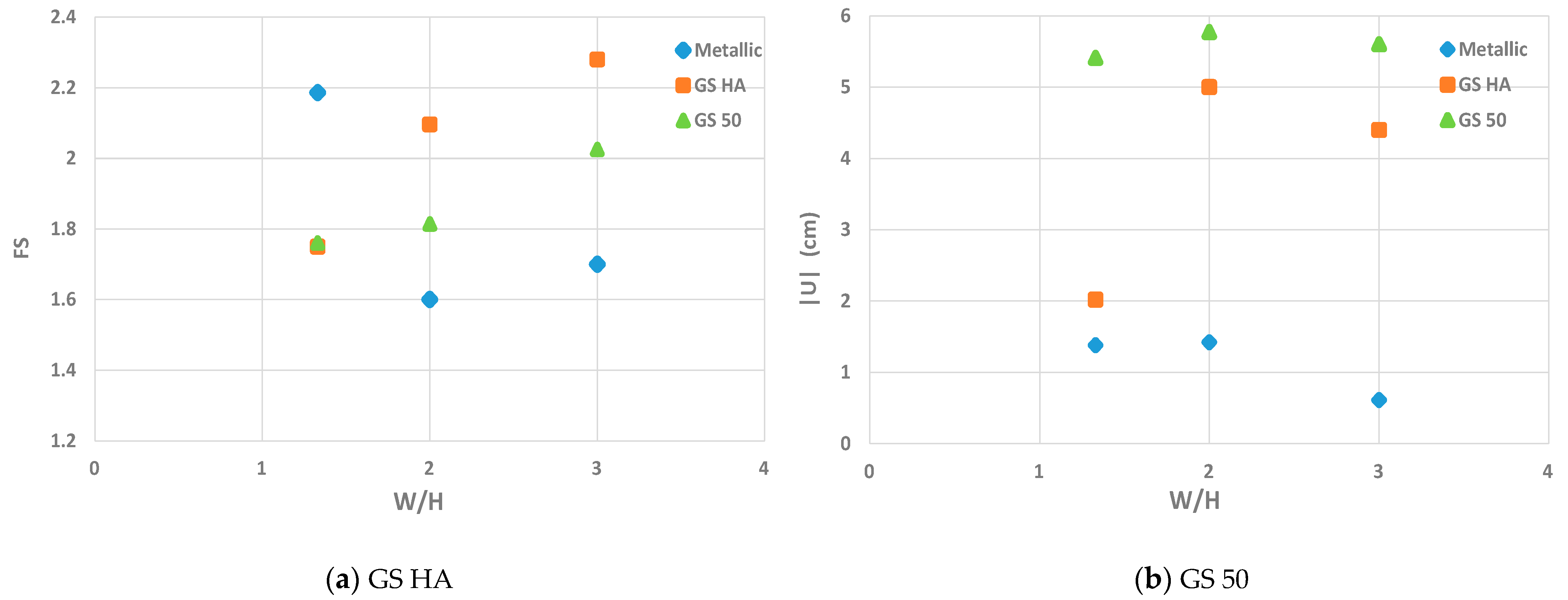
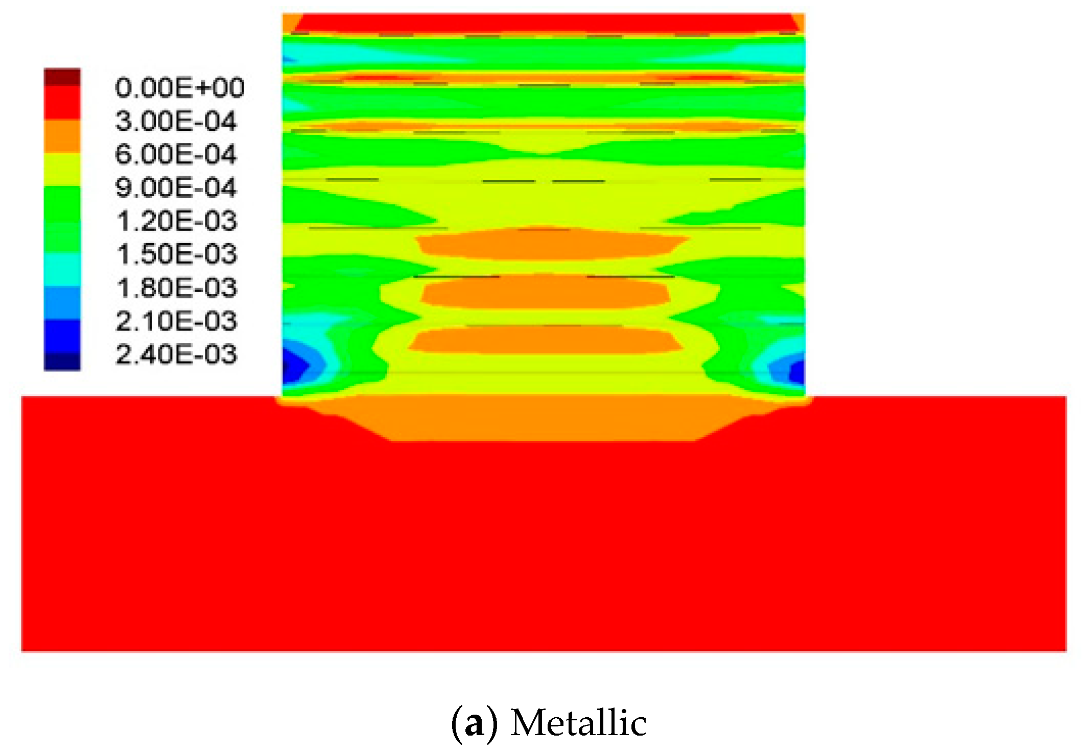
Ultimate Limit State of Walls
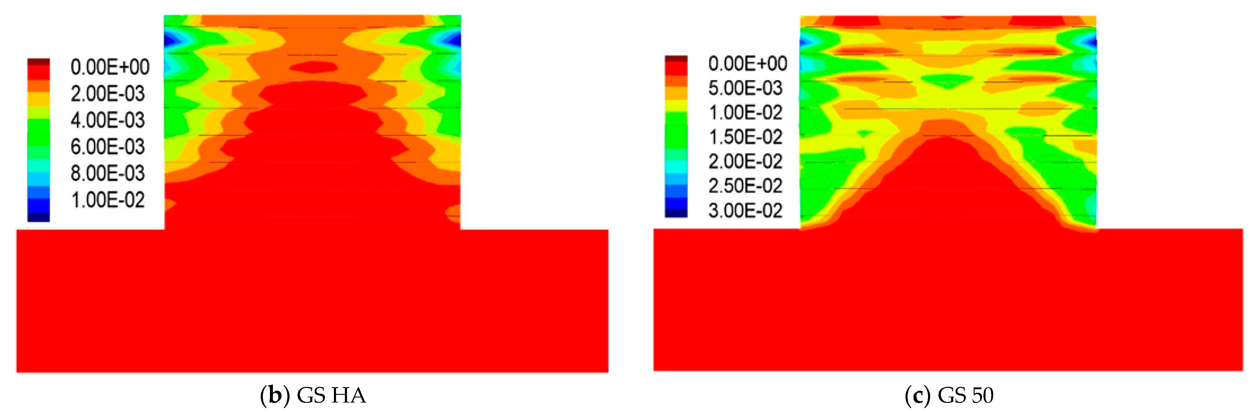
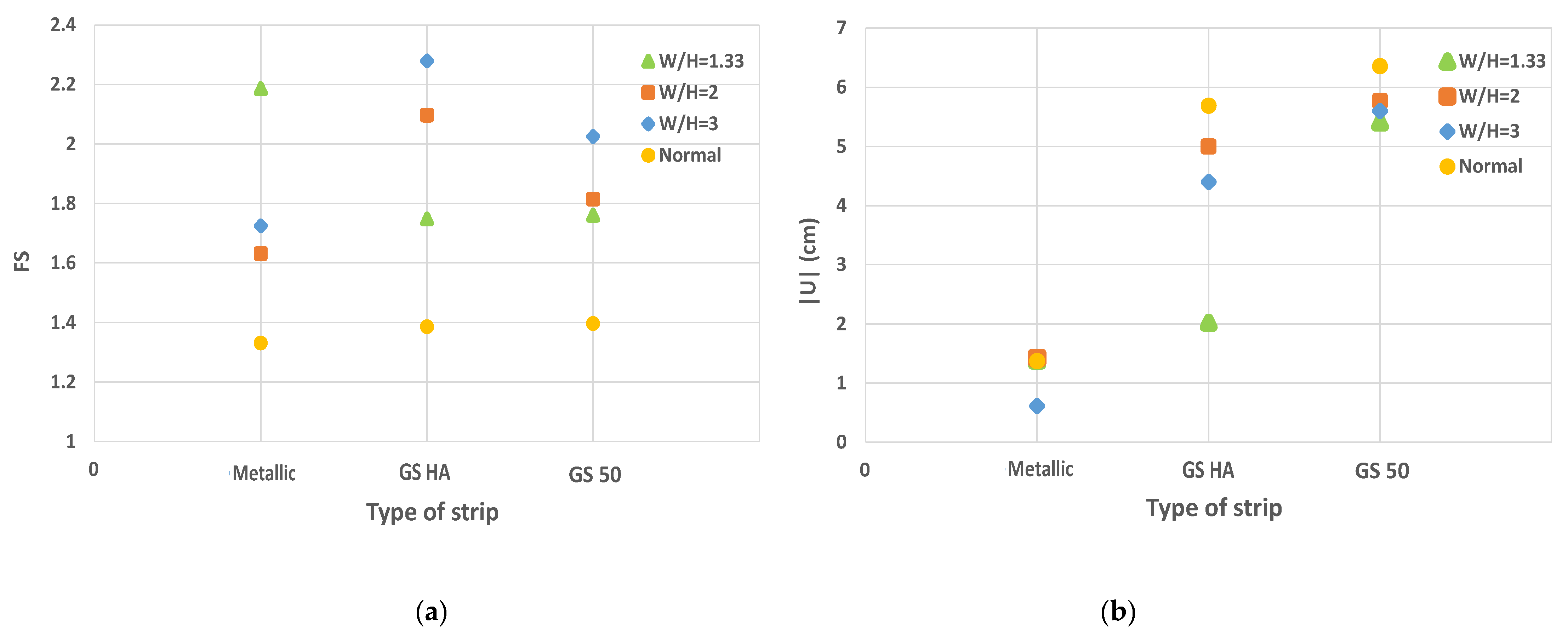
3.3.2. Influence of the Strip Type
4. Conclusions
- The results show that the back-to-back walls with geosynthetic strips have more flexibility than those with the metallic ones. This flexibility leads to higher displacements and, consequently, to higher soil/strip interface shear displacements and horizontal displacements. This is due to the lower rigidity of the geosynthetic strips.
- In contrast, the study of the back-to-back walls considering different width to height ratios showed that as the width of the wall decreases and the strips become closer to each other (D = 0), the mobilization of the tensile forces at the wall center lead to a reduction in the geosynthetic strips’ performance. In addition, the comparison between different W/H walls ratio shows that when the walls become closer, the wall stability increases, and the walls’ displacements decrease. The best performance (higher stability and lower dispacement) is related to walls with a W/H = 1.33 considering metallic strips.
- The results of back-to-back reinforced soil walls considering different ratios of width to height indicate that this ratio is directly connected to the tensile forces, and it is inversely related to soil/strip interface shear displacements. In other words, as the width of the wall becomes greater and the distance of the reinforcement strip increases, the tensile force on the reinforcement strips decreases. On the other hand, by increasing the width of the wall, the soil/strip interface shear displacements increase for both the metallic and synthetic strips. The failure is also highly impacted by the width to height ratio and the type of reinforcement strip.
- The results show that the soil friction angle has a significant effect on the behavior of the back-to-back walls. As this friction angle decreases, the stability of the wall decreases, and the soil/strip shear displacements and the tensile forces on the reinforcement increase.
- For back-to-back walls considering D > (45° − φ/2), each of the walls can be designed separately because the results are close but not equal.
Author Contributions
Funding
Institutional Review Board Statement
Informed Consent Statement
Data Availability Statement
Conflicts of Interest
References
- Jones, C.J. Earth Reinforcement and Soil Structures; Butterworth and Co. Ltd.: Oxford, UK, 1985. [Google Scholar]
- Iran Guideline for Design of Retaining Walls. 2005. Available online: www.sama.mporg.ir (accessed on 13 January 2021).
- Elias, V.; Christopher, B.R. Mechanically Stabilized Earth Walls and Reinforced Soil Slopes Design and Construction Guidelines; Federal Highway Administration: Washington, DC, USA, 1997.
- Leshchinsky, D.; Han, J. Geosynthetic reinforced multitiered walls. J. Geotech. Geoenvironmental Eng. 2004, 130, 1225–1235. [Google Scholar] [CrossRef]
- Han, J.; Leshchinsky, D. Stability analyses of geosynthetic reinforced earth structures using limit equilibrium and numerical methods. In Proceedings of the 8th international geosynthetics conference, Yokohama, Japan, 18–22 September 2006; pp. 1347–1350. [Google Scholar]
- Han, J.; Leshchinsky, D. Stability analysis of back-to-back MSE walls. In Proceedings of the 5th International Symposium on Earth Reinforcement, Fukuoka, Japan, 13–17 November 2007; pp. 487–490. [Google Scholar]
- Han, J.; Leshchinsky, D. Analysis of back-to-back mechanically stabilized earth walls. Geotext. Geomembr. 2010, 28, 262–267. [Google Scholar] [CrossRef]
- El-Sherbiny, R.; Ibrahim, E.; Salem, A. Stability of Back-to-Back Mechanically Stabilized Earth Walls. In Geo-Congress 2013; American Society of Civil Engineers: San Diego, CA, USA, 2013; pp. 555–565. [Google Scholar]
- Djabri, M.; Benmebarek, S. FEM Analysis of Back-to-Back Geosynthetic-Reinforced Soil Retaining Walls. Int. J. Geosynth. Ground Eng. 2016, 2, 26. [Google Scholar] [CrossRef] [Green Version]
- Sasanka, M.S.; Umashankar, B.; Madhira, R.M. Reinforcement Tensile Forces in Back-to-Back Retaining Walls. Geotech. Appl. 2019, 173–181. [Google Scholar]
- Won, M.S.; Kim, Y.S. Internal deformation behavior of geosynthetic-reinforced soil walls. Geotext. Geomembr. 2007, 25, 10–22. [Google Scholar] [CrossRef]
- Leshchinsky, D.; Ling, H.I.; Wang, J.P.; Rosen, A.; Mohri, Y. Equivalent seismic coefficient in geocell retention systems. Geotext. Geomembr. 2009, 27, 9–18. [Google Scholar] [CrossRef]
- Abdelouhab, A.; Dias, D.; Freitag, N. Physical and analytical modelling of geosynthetic strip pullout behaviour. Geotext. Geomembr. 2009, 28, 44–53. [Google Scholar] [CrossRef]
- Abdelouhab, A.; Dias, D.; Freitag, N. Numerical analysis of the behaviour of mechanically stabilized earth walls reinforced with different types of strips. Geotext. Geomembr. 2010, 29, 116–129. [Google Scholar] [CrossRef]
- Ho, S.K.; Rowe, R.K. Prediction behavior of two centrifugal model soil walls. Geotech. Eng. 1994, 120, 1845–1873. [Google Scholar] [CrossRef]
- Hatami, K.; Bathurst, R.J. Parametric analysis of reinforced soil walls with different backfill material properties. In Proceedings of the NAGS’ Conference, Las Vegas, NV, USA, 1–3 December 2006; pp. 1–15. [Google Scholar]
- Skinner, G.D.; Rowe, R.K. Design and behaviour of a geosynthetic reinforced retaining wall and bridge abutment on a yielding foundation. Geotext. Geomembr. 2005, 23, 235–260. [Google Scholar] [CrossRef]
- Al Hattamleh, O.; Muhunthan, B. Numerical procedures for deformation calculations in the reinforced soil walls. Geotext. Geomembr. 2006, 24, 52–57. [Google Scholar] [CrossRef]
- Bergado, D.T.; Teerawattanasuk, C. 2D and 3D numerical simulations of reinforced embankments on soft ground. Geotext. Geomembr. 2008, 26, 39–55. [Google Scholar] [CrossRef]
- Huang, B.; Bathurst, R.J.; Hatami, K. Numerical study of reinforced soil segmental walls using three different constitutive soil models. Geotech. Geoenvironmental Eng. 2009, 135, 1486–1498. [Google Scholar] [CrossRef]
- Hoe, I.L.; Huabei, L. Deformation analysis of reinforced soil retaining walls—Simplistic versus sophisticated finite element analyses. Acta Geotech. 2009, 4, 203–213. [Google Scholar]
- Schanz, T.; Vermeer, P.A.; Bonnie, P.G.R. The Hardening Soil Model: Formulation and Verification. Beyond 2000. In Computational Geotechnics–10 Years of Plaxis; Brinkgreve, R.B.J., Ed.; Balkema: Rotterdam, The Netherlands, 1999. [Google Scholar]
- FLAC2D. User’s Guide; Itasca Consulting Group: Minneapolis, MN, USA, 2017. [Google Scholar]
- Yu, Y.; Bathurst, R.J.; Miyata, Y. Numerical analysis of a mechanically stabilized earth wall reinforced with steel strips. Soils Found. 2015, 55, 536–547. [Google Scholar] [CrossRef]
- Cambou, B.; Jafari, K. A constitutive model for granular materials based on two plasticity mechanisms. In Constitutive Equations for Granular Non-Cohesive Soils; Saada, A.S., Ed.; Balkema: Rotterdam, The Netherlands, 1987; pp. 149–167. [Google Scholar]
- Federal Highway Administration. Design of Mechanically Stabilized Earth Walls and Reinforced Soil Slopes and Reinforced Soil Slope; Federal Highway Administration: Washington, DC, USA, 2009; Volume 1.


| Parameter | Value |
|---|---|
| Volumic weight (kg/m3) | 1580 |
| E50 ref 1 (MPa) | 50 |
| Eoed ref 2 (MPa) | 60 |
| Eur3 (MPa) | 145 |
| Failure Ratio | 0.7 |
| Cohesion (kPa) | 0 |
| Dilatancy angle (°) | 6 |
| Friction angle (°) | 36 |
| Parameter | E 1 (MPa) | ν 2 | γ 3 (kg/m3) |
|---|---|---|---|
| Concrete panel | 15 | 0.2 | 2500 |
| Soil foundation | 200 | 0.25 | 2200 |
| Parameter | Normal Stiffness (MPa) | Shear Stiffness (MPa) | Interface Friction Angle |
|---|---|---|---|
| Concrete panel/soil interface | 1000 | 1000 | 24 |
| Reinforcement | (GS50) 1 Geosynthetic Strip | (GS HA) 2 Geosynthetic Strip | Metallic Strip |
|---|---|---|---|
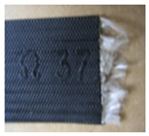 |  |  | |
| Elastic modulus (GPa) | 2.5 | 2.5 | 210 |
| Width (m) | 0.1 | 0.1 | 0.05 |
| Thickness (mm) | 3 | 3 | 4 |
| Strip tensile yield-force limit (kN) | 100 | 70 | 100 |
| Strip compressive yield-force limit (N) | 0.0 | 0.0 | 100 |
| Tensile failure strain limit of the strip (%) | 12 | 12 | 10 |
| Parameter | (GS 50) Geosynthetic Strip | (GS HA) Geosynthetic Strip | Metallic Strip |
|---|---|---|---|
| f*0 Initial apparent friction coefficient at the soil/strip interface | 1.2 | 2.5 | 1.5 |
| f*1 Minimum apparent friction coefficient at the soil/strip interface | 0.6 | 1 | 0.727 |
| kb (MN/m2/m) Shear stiffness at the soil strip interface | 0.22 | 0.25 | 1.6 |
| Strip | W 1/H 2 | φ (°) 3 | Fs 4 | |U| 5 (cm) | % Decrease Fs | % Increase |U| | ||
|---|---|---|---|---|---|---|---|---|
| (36–30) | (30–25) | (36–30) | (30–25) | |||||
| Metallic | 3 | 36 | 1.7 | 1.38 | 21 | 19 | 31.3 | 35.8 |
| 30 | 1.3 | 2.01 | ||||||
| 25 | 1.1 | 3.13 | ||||||
| 2 | 36 | 1.6 | 1.42 | 20.2 | 20 | 36 | 32.1 | |
| 30 | 1.3 | 2.22 | ||||||
| 25 | 1.0 | 3.27 | ||||||
| 1.33 | 36 | 2.2 | 0.61 | 20.6 | 19 | 3.2 | 1.6 | |
| 30 | 1.7 | 0.63 | ||||||
| 25 | 1.4 | 0.64 | ||||||
| Strip | W/H | Fs | |U| (cm) |
|---|---|---|---|
| Metallic | 2 | 1.6 | 1.42 |
| 1.33 | 2.2 | 0.61 | |
| GS HA | 2 | 2.1 | 5.38 |
| 1.33 | 1.7 | 2.02 | |
| GS 50 | 2 | 1.8 | 5.74 |
| 1.33 | 1.7 | 5.41 |
| Strip | W/H | Tensile Force (kN) | Soil/Strip Shear Displacement (cm) |
|---|---|---|---|
| Metallic | 3 | 16.5 | 0.62 |
| 2 | 17.6 | 0.68 | |
| 1.33 | 20.4 | 0.14 | |
| Infinity | 18.6 | 0.89 |
| Strip | W/H | Fs | |U| (cm) | ∆Fs/Fs (I)% | ∆|U|/|U| (I) % |
|---|---|---|---|---|---|
| Metallic | 3 | 1.7 | 1.38 | +21.8 | +0.72 |
| 2 | 1.6 | 1.42 | +16.9 | +3.65 | |
| 1.33 | 2.2 | 0.61 | +39.5 | −55.5 | |
| Infinity | 1.33 | 1.37 | - | - | |
| GS HA | 3 | 2.28 | 4.4 | +65.2 | −22.7 |
| 2 | 2.1 | 5.38 | +52.2 | −5.45 | |
| 1.33 | 1.7 | 2.02 | +23.2 | −64.5 | |
| Infinity | 1.38 | 5.69 | - | - | |
| GS 50 | 3 | 2.02 | 5.6 | +45.3 | −11.95 |
| 2 | 1.8 | 5.74 | +29.5 | −9.75 | |
| 1.33 | 1.7 | 5.41 | +22.3 | −14.93 | |
| Infinity | 1.39 | 6.36 | - | - |
Publisher’s Note: MDPI stays neutral with regard to jurisdictional claims in published maps and institutional affiliations. |
© 2021 by the authors. Licensee MDPI, Basel, Switzerland. This article is an open access article distributed under the terms and conditions of the Creative Commons Attribution (CC BY) license (https://creativecommons.org/licenses/by/4.0/).
Share and Cite
Lajevardi, S.H.; Malekmohammadi, K.; Dias, D. Numerical Study of the Behavior of Back-to-Back Mechanically Stabilized Earth Walls. Geotechnics 2021, 1, 18-37. https://doi.org/10.3390/geotechnics1010002
Lajevardi SH, Malekmohammadi K, Dias D. Numerical Study of the Behavior of Back-to-Back Mechanically Stabilized Earth Walls. Geotechnics. 2021; 1(1):18-37. https://doi.org/10.3390/geotechnics1010002
Chicago/Turabian StyleLajevardi, Seyed Hamid, Khashayar Malekmohammadi, and Daniel Dias. 2021. "Numerical Study of the Behavior of Back-to-Back Mechanically Stabilized Earth Walls" Geotechnics 1, no. 1: 18-37. https://doi.org/10.3390/geotechnics1010002
APA StyleLajevardi, S. H., Malekmohammadi, K., & Dias, D. (2021). Numerical Study of the Behavior of Back-to-Back Mechanically Stabilized Earth Walls. Geotechnics, 1(1), 18-37. https://doi.org/10.3390/geotechnics1010002