1. Introduction
In the context of the global energy transition to a low-carbon economy and sustainable energy sources, technologies capable of ensuring high energy efficiency with minimal environmental impact are acquiring particular significance [
1]. Among such solutions, a special place is occupied by fuel cells—electrochemical energy converters in which the process of generating electricity is carried out directly from the chemical energy of the fuel, without an intermediate thermal stage [
2]. This allows us to achieve high efficiency, reduce greenhouse gas emissions, and increase the reliability of energy systems. One of the most promising areas in this field are solid oxide fuel cells (SOFCs), characterized by high efficiency, a long service life, a wide range of applicable fuels, and the ability to be combined with other energy sources, such as solar panels, gas turbines, and heat recovery systems [
3].
SOFCs are multilayer structures comprising a porous anode, a dense ion-conducting electrolyte, and a porous cathode, each of which performs strictly defined functions and imposes specific requirements on its composition, microstructure, and production method. The main design types of SOFCs include flat and tubular cells, as well as cells on a ceramic or metal supporting substrate. The transition from high-temperature (900–1000 °C) to intermediate-temperature (500–800 °C) operation, aimed at increasing material durability, reducing costs, and accelerating system startup, requires improved technologies for producing components with specified properties, as well as the implementation of new methods for depositing thin, dense layers with a high degree of homogeneity and adhesion [
4,
5].
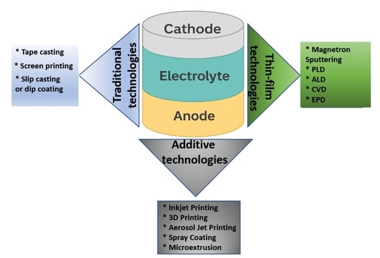
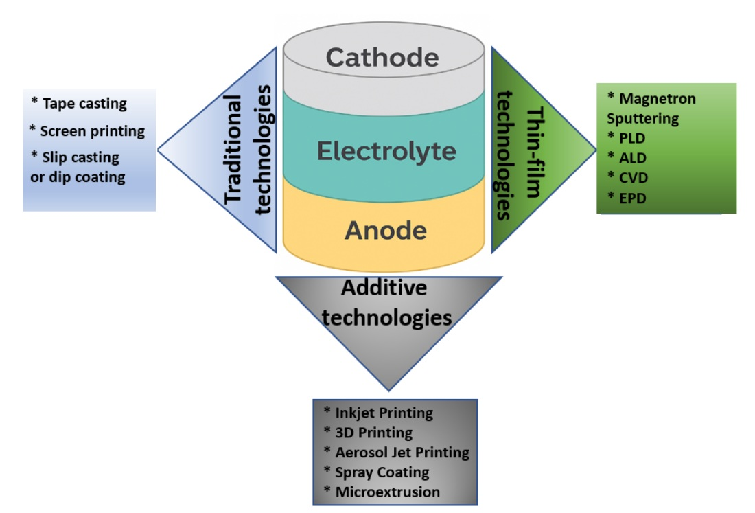
Traditionally, SOFCs have been manufactured using ceramic technology methods: molding followed by sintering, screen printing, casting onto a substrate, and hot pressing. However, these methods have a number of limitations associated with achieving the required electrolyte density at low sintering temperatures, controlling the porosity of the functional layers, and limited miniaturization capabilities. The primary benefit of transitioning from conventional 10–50 µm electrolytes to sub-micrometer thin films is the substantial reduction in ohmic losses, which scale linearly with electrolyte thickness and dominate the total voltage loss at intermediate temperatures (500–700 °C). Once the electrolyte becomes sufficiently thin, the overall performance becomes increasingly limited by polarization losses associated with electrode kinetics rather than ionic conduction. However, when the film thickness approaches the sub-100 nm regime, gas-tightness may become a limiting factor, particularly under high fuel utilization or elevated oxygen partial-pressure gradients, where defect-mediated permeation can compromise open-circuit voltage and efficiency [
6]. In this regard, over the past two decades, physicochemical thin-film deposition methods have been actively developed, such as magnetron sputtering [
7], pulsed laser deposition (PLD) [
8], atomic layer deposition (ALD) [
9], chemical vapor deposition (CVD) [
10], electrophoretic deposition (EPD) [
11], etc. These methods allow us to obtain films with a high degree of control over thickness, density, and composition, which is especially important when creating multilayer and gradient structures [
12].
At the same time, there is growing interest in additive technologies, including 3D printing and inkjet printing, which offer new possibilities in the design and production of SOFCs with unconventional geometries, localized compositions, and scalability potential [
13]. Hybrid approaches, combining traditional and modern application methods, are also a promising direction, allowing the “structure–property–functionality” principle to be realized at a new level [
14].
The purpose of this review article is to systematize and analyze existing methods for creating solid oxide fuel cells (SOFCs), focusing on the materials used, methods for depositing functional layers, and the architectural features of the fuel cells. This paper examines both established and innovative technologies, as well as their potential applications for reducing operating temperatures, improving electrochemical performance and durability, and creating compact and scalable systems. This review can serve as a methodological basis for developing new process routes aimed at creating highly efficient solid oxide energy systems.
2. Materials for Solid Oxide Fuel Cells
Current trends in the development of SOFC materials are driven by the need to increase their efficiency, power density, and durability, as well as to reduce operating temperatures to the range of 500–800 °C [
15]. This transition requires the selection of new functional materials that provide high ionic and electronic conductivity, chemical and thermomechanical stability, and compatibility at phase boundaries. Environmental and economic factors are also becoming significant—preference is given to materials containing readily available, abundant, and relatively inexpensive elements [
16]. A summary of key materials used in SOFCs is given in
Table 1.
3. Methods for Creating SOFC Layers
The formation of anode, electrolyte, and cathode layers with specified morphological and functional characteristics plays a key role in ensuring high efficiency and stability of SOFCs [
33]. Material deposition methods directly determine the density of the ionic electrolyte, the porosity and active surface area of the electrodes, the adhesion between layers, and the thermomechanical compatibility in a multilayer architecture [
34]. There are two main classes of technologies for the formation of SOFC layers: traditional methods historically used in the ceramic industry, and modern physicochemical methods of thin-film and additive deposition [
35]. This section discusses the key features of each approach, their advantages, and limitations in the context of creating cells for both stationary and compact, portable fuel cells.
3.1. Traditional Methods
Historically, traditional methods for creating SOFC layers have been based on classical ceramic technologies such as casting, pressing, sintering, and paste deposition [
36]. These methods were developed long before the advent of thin-film technologies and have been extensively used in the production of ceramic components, capacitors, sensors, and other products. In the field of SOFCs, they are primarily used in the fabrication of thick-film cells operating at temperatures above 800 °C, where the thickness of each layer can be tens or even hundreds of micrometers [
37]. Despite a number of technological limitations, these methods continue to play an important role in industrial production, providing ease of implementation, scalability, and the relatively low cost of equipment and materials.
3.1.1. Tape Casting
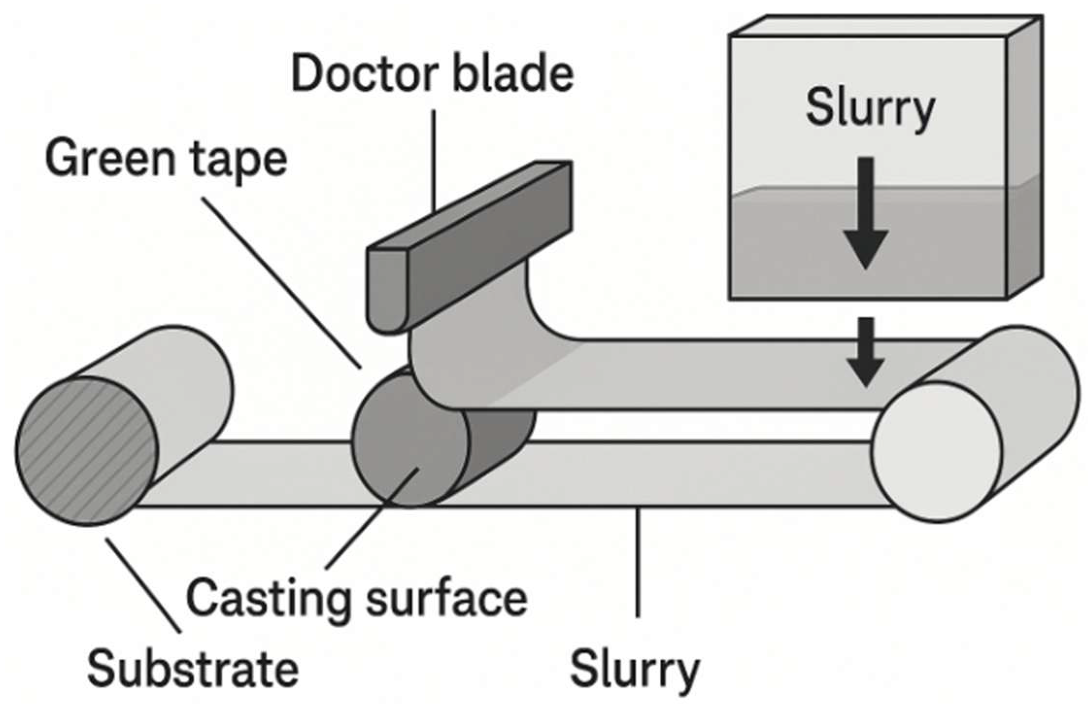
One of the most widely used methods is tape casting. This process involves applying a ceramic slurry (called slip), consisting of powder, solvent, plasticizers, and binders, to a flat, moving substrate using an adjustable knife (
Figure 1) [
38]. After the solvent evaporates, a flexible ceramic tape, known as a “green” tape, is formed. This tape can be easily cut, rolled, drilled, or laminated with other layers before sintering. Casting is used primarily to form dense substrates based on stabilized zirconia (YSZ), as well as to fabricate multilayer structures including electrodes and interconnects. The main advantages of the method include the ability to produce wide tapes (up to 30 cm or more), controlled thickness (30–500 μm), high productivity, and suitability for automation. However, the quality of the layer largely depends on the homogeneity of the suspension, the degree of deflocculation of the particles and the drying regime, the violation of which can lead to defects—delamination, cracks, porous areas [
39].
Ivanchenko et al. [
40] presented an approach to forming anode and electrolyte layers for SOFCs using slip casting on tape. Optimized suspensions based on NiO and 8YSZ with a viscosity of 12,000–22,000 mPa·s ensured the formation of uniform layers with a thickness of 100–400 μm (anode) and 50–150 μm (electrolyte). An analysis of defects characteristic of the casting process (central cracks, Benard cells, bubbles) was conducted, and methods for their elimination by adjusting the binder content and controlling the drying conditions were proposed. The effectiveness of step-by-step lamination of layers, which helps to avoid delamination during heat treatment, was also demonstrated. However, this method requires the precise control of rheological parameters and is accompanied by high energy consumption. The work provides valuable guidance for eliminating process defects, but does not contain data on long-term mechanical and electrochemical properties, which limits the assessment of the practical applicability of the layers in working cells.
Kwon and Han demonstrated [
41] the effectiveness of the slip tape casting method for forming dense La
0.8Sr
0.2Ga
0.85Mg
0.15O
3–δ (LSGM)-based electrolytes in electrolyte-supported SOFCs. Optimization of the suspension composition with a solvent content of 26.5% ensured uniform layers with a thickness of ~400 μm and a mechanical strength of the green ribbon of up to 3.25 MPa. The fabricated cells achieved a power of 0.476 W/cm
2 at 800 °C and an open-circuit voltage of 1.05 V. The advantages of the technology are simplified degassing and the absence of a buffer layer, which reduces the technological complexity. However, high sensitivity to suspension viscosity and drying conditions requires precise control, which may limit scalability. The lack of data on long-term electrochemical stability and mechanical reliability limits the completeness of the assessment of the operational potential of the developed structures.
Parvaix et al. [
42] developed a technology for forming anode-supported SOFCs using aqueous reverse sequential tape casting. Optimized suspensions based on NiO–8YSZ, 8YSZ, and 10GDC included non-toxic binders (PVA, PEG), which allowed for a reduction in the content of organic components. Co-sintering of a three-layer structure (530 μm anode/80 μm electrolyte/30 μm cathode) at 1450–1500 °C ensured the production of flat, defect-free samples. The cells achieved a power of 319 mW/cm
2 at 830 °C, confirming the electrochemical activity of the architecture. Despite the efficiency of the approach, the method remains sensitive to viscosity parameters and drying conditions. Precise thickness control is necessary, especially for thin electrolytes, as well as long-term stability and thermal stability analysis. This work demonstrates the potential of an environmentally friendly approach to forming multilayer SOFC structures, but requires further validation to assess its applicability in industrial settings.
Advanced Variants of Tape Casting: Phase Inversion and Freeze-Drying Approaches
In addition to conventional tape casting, several advanced variants of this method have been developed to overcome the limitations associated with pore control, thickness uniformity, and gas transport in SOFC components. Among them, phase inversion tape casting and freeze-drying tape casting have received increasing attention due to their ability to create highly porous, lightweight, and structurally optimized substrates. Phase inversion tape casting is based on the controlled exchange between a polymer-containing ceramic slurry and a non-solvent bath, leading to instantaneous phase separation and the formation of interconnected pore networks. This method enables precise control of pore size, morphology, and gradient structures, making it highly suitable for fabricating porous anode supports, gas-diffusion layers, and membranes with tailored mass-transport properties. Recent studies demonstrated its potential for creating mechanically robust substrates with channel-like porosity and high permeability, which are advantageous for IT-SOFC and MS-SOFC architectures [
43,
44,
45,
46,
47,
48,
49].
Freeze-drying tape casting involves freezing a ceramic slurry and subsequently sublimating the ice under vacuum, resulting in highly porous, anisotropic structures with aligned pore channels. This approach enables the formation of lightweight substrates with high gas diffusivity and reduced thermal mass, which can increase electrochemical performance in tubular and planar SOFC systems. The technique has been shown to produce hierarchical porosity beneficial for triple-phase boundary formation and improved fuel utilization [
50,
51,
52,
53]. These methods significantly expand the functional landscape of traditional tape casting and should be considered as integral parts of modern SOFC layer fabrication strategies.
3.1.2. Screen Printing
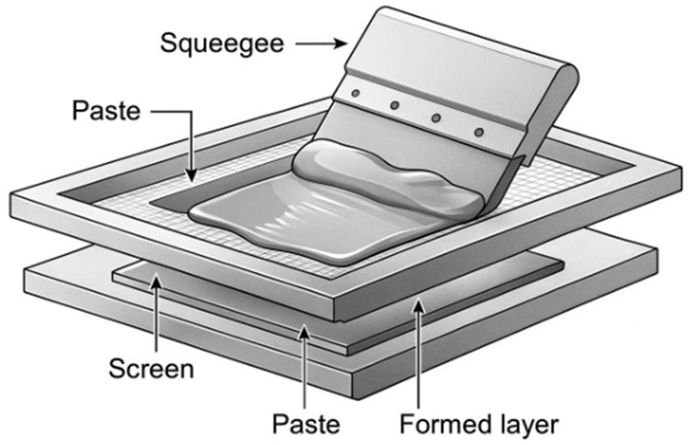
Another important method is screen printing, which is used to deposit anodic, cathodic, and buffer layers on top of an already formed substrate (
Figure 2). A high-viscosity paste containing ceramic powder, organic binders, and additives is passed through a stencil (screen) onto a specified area of the substrate. After deposition, the layer is dried and then sintered. Screen printing allows for the production of layers with a thickness of approximately 10–50 μm and high shape reproducibility. This method is convenient for producing cells with complex geometries and is widely used to create functional layers with a specific topology, including cylindrical or planar substrates [
54]. However, the method requires careful adjustment of the paste viscosity, the screen mesh density, and the deposition mode, and is also accompanied by mandatory high-temperature heat treatment.
Mashuri and Abd Rahman [
55] investigated the possibility of forming multilayer MS-SOFC structures by screen printing on a SS430 metal substrate. The compositions of NiO–GDC (anode), GDC (electrolyte), and LSCF–GDC (cathode) pastes were optimized, and the effect of mesh parameters (305 and 355 mesh) was analyzed. The best results were obtained using a 305 mesh and tenfold deposition, which ensured the formation of layers of ~12 μm thickness (anode and electrolyte) and ~18 μm (cathode) with low polarization resistance. Despite the achieved reproducibility and dense packing, the screen printing method is limited in the accuracy of thickness control and uniformity, especially with multiple deposition. Defects are possible that affect the stability and durability of the cells. Nevertheless, the work demonstrates the potential of this approach for low-temperature and scalable MS-SOFCs, subject to further optimization of layers and deposition parameters.
Ried et al. [
56] developed thixotropic pastes based on 8YSZ (Y
0.16Zr
0.84O
1.92) for the formation of dense electrolytes by screen printing in anode-supported SOFCs. The use of Unitec and Tosoh powders with a solid phase content of up to 50%, organic binders (PVB B30H/B20H) and dispersants (Solsperse 3000, PVP) made it possible to obtain pastes with a viscosity of ≤12 Pa·s at 100 s
−1. After sintering at 1430 °C, gas-impermeable films with a thickness of ~20 μm were formed, with a resistivity of ~46 Ω cm at 800 °C and an activation energy of 96–99 kJ/mol, which is consistent with published values. However, the high sintering temperature limits the applicability of the technology in multilayer structures due to the risk of grain boundary phase formation and interphase reactions. To improve compatibility with other cell components, a lower synthesis temperature is required, for example, by using nanopowders or complex pastes with dissolved Y and Zr ions. This study confirms the potential of screen printing for producing dense electrolytes but highlights the need for further optimization of processing temperatures.
3.1.3. Slip Casting or Dip Coating
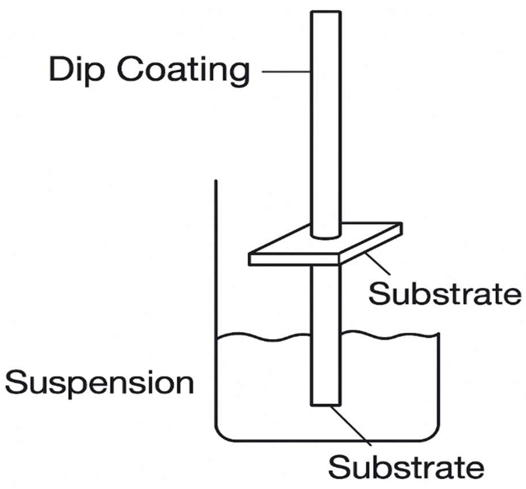
Slip casting or dip coating (
Figure 3) is often used to deposit thin electrode layers, particularly on tubular substrates. In this method, the workpiece is immersed in a suspension for a short time, then removed at a specified rate, and the resulting film on the surface is dried and sintered. This method is simple and inexpensive, but it requires high suspension homogeneity and strict control of deposition conditions. Uneven thickness, sagging, or delamination are typical defects that occur when process parameters are not met [
57].
Zhang et al. [
58] developed a combined method for fabricating anode-supported tubular SOFCs by combining slip casting to form the anode substrate and dip coating of 8YSZ electrolyte without vacuum assistance. The resulting membranes, ~20 μm thick, exhibited high density and no cracks, and provided an open-circuit voltage of 1.05 V and a maximum power of 1.1 W/cm
2 at 800 °C. Impedance analysis revealed that up to 75% of the total resistance was due to electrode polarization, and the specific resistance of the electrolyte was 40.5 Ω·cm at 800 °C. The main limitations of the technology are the need for multiple dipping to achieve a given thickness and significant shrinkage in the z-direction (~22.5%) after sintering, which may affect reproducibility. Furthermore, high polarization losses indicate the need for refinement of the electrode architecture. Despite this, the proposed approach demonstrates high technological and economic efficiency for the formation of dense electrolyte membranes in tubular SOFCs without the use of vacuum systems.
Jang et al. [
59] proposed an efficient approach to modify the anode functional layer (AFL) in IT-SOFCs by forming a microrelief surface using the deep coating method and adding burnable carbon particles (>10 μm). The increased AFL roughness (Rq = 307 nm, Rpv = 3074 nm), confirmed by AFM, contributed to the improved GDC electrolyte coverage and the increase in the area of triple phase boundaries. As a result, a peak power of 0.59 W/cm
2 was achieved at 650 °C, which is 74% higher than that of the unmodified AFL cell. Electrochemical impedance showed a decrease in the overall resistance, mainly due to a decrease in the polarization contribution. The method is technologically simple and scalable, and does not require vacuum systems. However, the tests are limited to button cells with an area of 1 cm
2 and do not include long-term stability. The authors rightly point out the potential of extending the approach to both sides of the electrolyte to further improve the TPB and output characteristics of IT-SOFCs.
Hanifi et al. [
60] presented a technology for the fabrication of anode-supported tubular SOFCs combining slip casting of porous YSZ substrates with high-cycle catalyst infiltration. The anode was modified by infiltration with Ni, Ce, and Sm solutions, forming the active NiO–SDC phase. The cathode structures were different: LSM infiltration into porous YSZ (cell B) and LSCF–GDC deposition on a GDC buffer layer (cell A). Cell A demonstrated higher power (275 mW/cm
2 at 800 °C) and stability compared to cell B (198 mW/cm
2), which is associated with exceeding the Ni percolation threshold (10% versus 4%). The method ensures efficient infiltration even into closed pores and is applicable to highly porous substrates. The main limitations are the need for up to 35 infiltration cycles to achieve the desired conductivity and the risk of oversaturation of the internal walls. The study highlights the potential of the infiltration approach for creating stable and scalable tubular SOFCs, while emphasizing the need to optimize the active phase content and electrode architecture.
Hedayat and Du developed [
61] a fabrication technology for anode-supported tubular SOFCs based on slip casting of NiO/3YSZ (65:35) tape, its rolling and bonding using ethanol/α-terpineol, and deposition of functional layers by deep coating. After co-sintering at 1450 °C and 1150 °C, a structure with an anode substrate (~900 μm), a dense electrolyte (18 μm), and a cathode (18 μm) was obtained. SEM confirmed the integrity of the layers and the density of the electrolyte. At 800 °C, the cell showed an OCV of 1.08 V, a power density of 281 mW/cm
2, and ohmic and polarization resistances of 0.60 and 0.30 Ω·cm
2, respectively. The method provides reliable lamination and gas impermeability, but is limited by high sintering temperatures and requirements for uniform microstructure during scaling.
A characteristic feature of all traditional methods is the need for high-temperature sintering, typically in the range of 1200–1400 °C [
62]. This is due to the need to form a dense electrolyte structure and ensure strong adhesion between the layers. However, such heat treatment leads to a number of limitations. Firstly, it is incompatible with metal substrates, which can deform or oxidize at high temperatures. Secondly, during long-term sintering, mutual penetration of components at the phase boundaries is possible, which leads to the formation of undesirable secondary phases (for example, SrZrO
3 at the LSCF/YSZ boundary), which impair conductivity and accelerate degradation [
63]. In addition, high-temperature heat treatment is accompanied by significant shrinkage, which can cause the appearance of microcracks, delamination, and a decrease in mechanical reliability [
64].
Despite these shortcomings, traditional methods remain the foundation for the mass production of ceramic SOFCs and are often used in conjunction with modern approaches. In particular, they are used to form support structures and as a preliminary step before depositing thin-film functional layers using physicochemical methods. Thus, traditional technologies remain relevant even in the context of new developments, particularly in the transition to hybrid and multilayer architectures, which require a combination of mechanical strength and high electrochemical activity.
3.2. Modern Methods of Thin-Film Deposition of SOFC Materials
Current developments in SOFC technology demonstrate a steady transition from traditional ceramic technologies to precision physicochemical deposition methods aimed at forming functional layers with thicknesses ranging from a few nanometers to several micrometers [
54]. The primary goal of using thin-film methods is to achieve high density, controlled porosity, thickness uniformity, and improved adhesion to the substrate, which is critical for increasing power density, reducing thermal losses, and increasing device durability. These methods enable the implementation of multilayer, nanostructured, and graded architectures required for next-generation cells, including microSOFCs and devices on flexible/metal substrates [
65].
3.2.1. Magnetron Sputtering
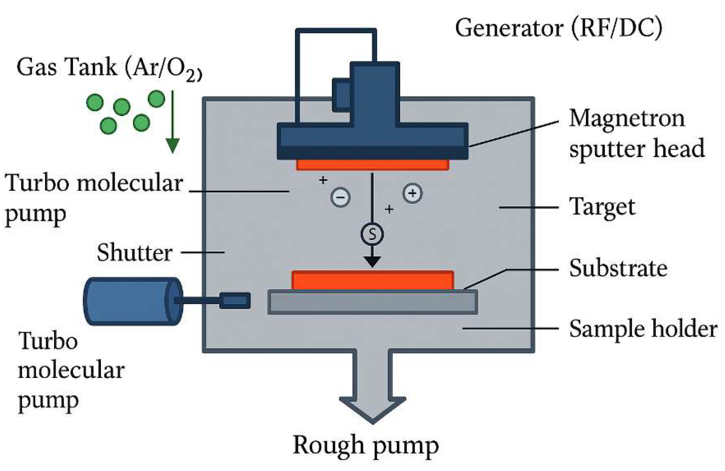
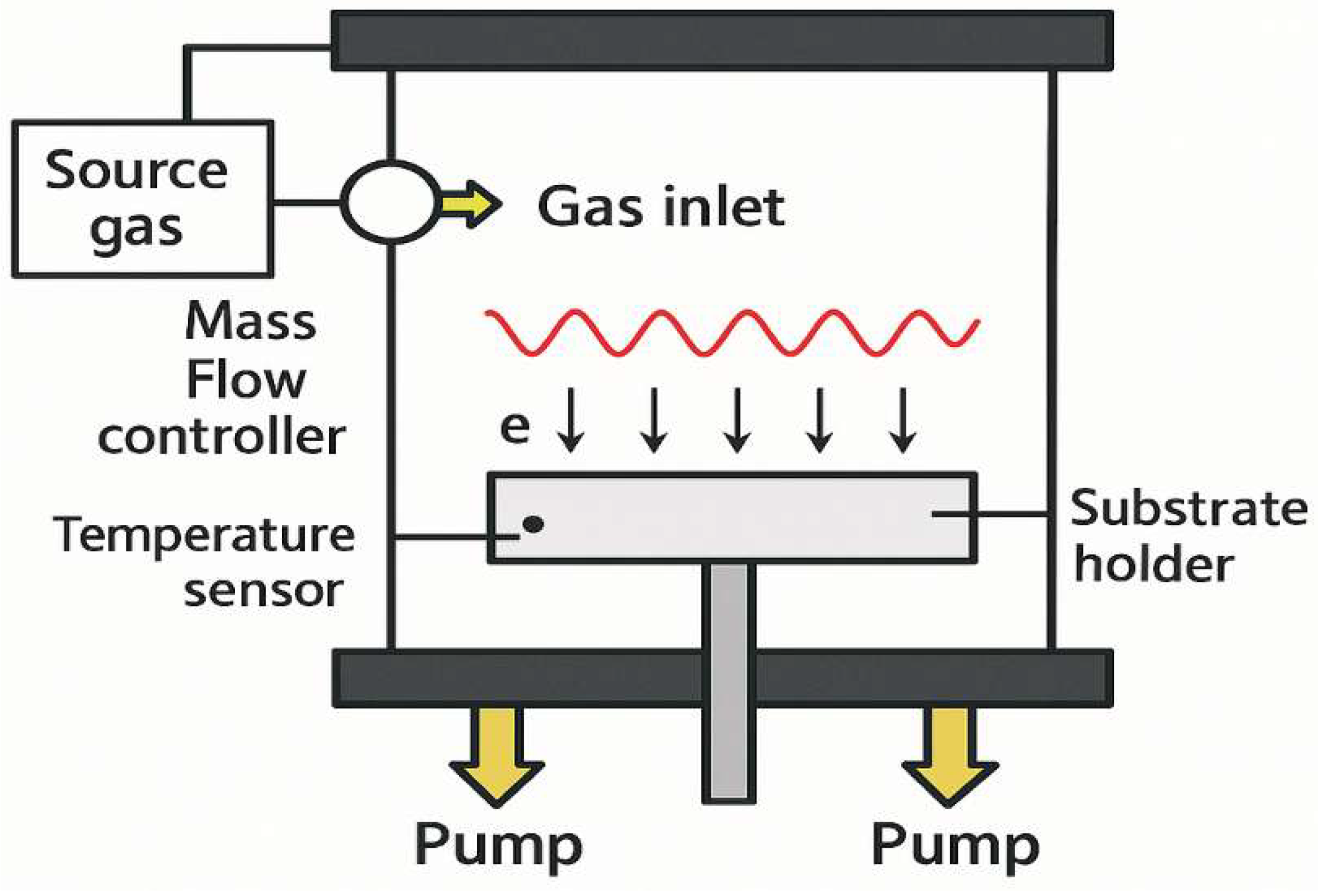
Magnetron sputtering is currently one of the most versatile and widely used technologies for producing thin-film SOFC components (
Figure 4). This method enables the deposition of oxide materials of various compositions as dense, uniform films with high adhesion and low impurity content. Depending on the discharge type (DC, RF, reactive mode), it is possible to deposit both conductive and dielectric layers with precise control of the deposition parameters [
66]. In recent years, particular attention has been paid to optimizing reactive magnetron sputtering, in which a mixture of argon and oxygen is supplied to the working chamber, ensuring the synthesis of oxide phases directly on the substrate. This allows for the production of thin layers of YSZ, GDC, and LSGM electrolytes with high density at temperatures of 400–600 °C, which is critical for the formation of cells on metal substrates that cannot withstand traditional sintering at T > 1200 °C. The use of preheated substrates and multilayer deposition (e.g., YSZ/CGO) can reduce defects and increase the ionic conductivity of the film [
67].
Solovyev et al. [
68] demonstrated the efficiency of reactive magnetron sputtering for the preparation of thin-film electrolytes based on SDC and multilayer SDC/YSZ/SDC structures in IT-SOFCs. A single-layer SDC electrolyte with a thickness of 5.5 μm provided a power of 651 mW/cm
2 at 650 °C, but was limited by a low OCV (~0.8 V) due to electron conductivity. The introduction of an intermediate YSZ layer (1 μm) increased the OCV to 1.1 V and achieved a peak power of 2263 mW/cm
2 at 800 °C. Impedance analysis confirmed the optimal resistance balance for this configuration. SEM and X-ray diffraction analysis, including synchrotron radiation, confirmed the density and homogeneity of the layers. The work demonstrates the high accuracy and applicability of the method for the formation of efficient multilayer electrolytes with controlled barrier properties.
In this work [
69], the effect of a nanostructured NiO–YSZ-based anodic functional layer (AFL) deposited by reactive magnetron sputtering on the performance of anode-supported SOFCs was investigated. Films with a thickness of 2–4 μm were deposited on a commercial NiO–YSZ substrate and annealed at 1200 °C, which ensured the formation of a homogeneous porous structure after reduction. The AFL demonstrated high adhesion, close contact with the electrolyte, and nanoporous morphology (pores ~100–200 nm). Cells with an LSCF/CGO cathode and AFL (60 % NiO) achieved a peak power of 1240 mW/cm
2 at 800 °C, which is 30% higher than that of the control sample without AFL, and twice as high at 600 °C. Furthermore, the structure demonstrated high stability: after nine redox cycles at 750 °C, power degradation was only 11%. The magnetron-based AFL effectively increases the TPB and reduces interfacial stresses, acting as a buffer layer. This study confirms the high efficiency of this approach for improving the performance and thermal stability of IT-SOFCs.
Solovyev et al. [
70] studied the formation of thin-film electrolytes based on YSZ, CGO, and their bilinear combinations using asymmetric bipolar reactive magnetron sputtering. To ensure the density and tightness of the coating without sintering, additional pulsed electron beam treatment was used. YSZ electrolytes ≥ 4 μm thick provided an OCV of up to 1.1 V and a power density of 580 mW/cm
2 at 800 °C. CGO electrolytes demonstrated higher conductivity at 650–700 °C, but were limited in OCV (~0.85 V) due to electron conductivity. The best characteristics were achieved in the YSZ/CGO (4/1.5 μm) structure: OCV 1.124 V, power 1.25 W/cm
2 at 800 °C. Optimization of the 50 kHz process enabled high deposition rates (up to 6.5 μm/h for YSZ). Structural analysis confirmed the formation of a stable cubic phase without amorphous inclusions. This work demonstrates the potential of the low-temperature process for creating dense, hermetic, and efficient electrolytes, promising for industrial applications in IT-SOFCs.
High-power pulsed magnetron sputtering (HiPIMS) is a modern modification of the classical method that utilizes the generation of highly ionized plasma with short, powerful pulses. Due to the high energy of the target material ions deposited on the substrate, HiPIMS allows for the production of extremely dense, defect-resistant, and stable films [
71]. HiPIMS is known to be characterized by a high degree of ionization of the material sputtered from the cathode (up to 70%) and a high plasma concentration (up to 1013 cm
−3). This effect is achieved by applying short pulses with a high power density and a fill factor of several percent to the sputtered cathode. This results in the generation of plasma with a concentration several times greater than that of conventional DC magnetron sputtering [
72,
73]. The use of HiPIMS for the deposition of metallic and oxide coatings for various functional purposes has always resulted in improved performance.
In [
74], the authors compared pulsed direct current magnetron sputtering (DCMS) with high power impulse magnetron sputtering (HiPIMS) for the formation of YSZ coatings, and also examined the effect of bias voltage applied in each mode on the texture and crystallinity of the deposited coatings. It was shown that, regardless of the mode, the films were stoichiometric. However, applying bias voltage led to completely different results. Films deposited in the pulsed unipolar mode had a high degree of crystallinity and a <220> texture at high bias voltages (−75 V), while at a bias of −50 V and below, a mixed crystalline orientation in the <111> and <220> directions was observed. Regardless of the applied voltage, the films were columnar and had voids.
Different results were obtained for films deposited in the HiPIMS mode. High crystallinity and <220> orientation were observed when the films grew at a bias of −25 V. At −75 V, as a result of intense ion bombardment and the transfer of high kinetic energy to the growing film, the destruction of growing crystals and a decrease in grain size were observed, and the films were less ordered [
74].
As in the case of the pulsed unipolar mode, films deposited in the HiPIMS mode under floating potential were columnar and contained voids. At a high negative bias voltage (75 V), peeling of the coating from the substrate was observed, which could be caused by strong internal stresses generated in the film as a result of intense ion bombardment. Thus, for the HiPIMS mode, a voltage range of −25 V to −50 V was determined, at which it is possible to obtain dense coatings without pillars, voids, and cracks [
75].
T. Dejob et al. [
76] investigated the effect of reactive HiPIMS deposition parameters on the structure and protective properties of Mn
0.5Co
0.5O coatings intended for use as barrier layers on SOFC interconnects. Depending on the substrate temperature and bias voltage, coatings with different crystallographic orientations were obtained: without pronounced texture, with <111> and <200>. All samples demonstrated the ability to suppress Cr evaporation at 800 °C for 2000 h. The coating with the <200> orientation turned out to be the most effective, providing Cr retention of up to 93%, while the structure with the <111> orientation showed the worst result (~70%), which is associated with increased defectivity and instability of grain boundaries. Although Mn
0.5Co
0.5O coatings are inferior to metallic Co in terms of Cr retention (98%), they exhibit high structural stability, lack of Fe diffusion from the substrate, and do not require annealing. This study confirms the potential of oxide coatings produced by R-HiPIMS as an alternative to metal barrier layers in SOFC interconnects.
Thin-film electrolytes fabricated by different deposition methods exhibit distinct defect structures that strongly influence gas-tightness and ionic conductivity. Physical vapor deposition routes such as magnetron sputtering and HiPIMS often generate columnar microstructures and intercolumnar voids, arising from low adatom mobility and shadowing effects; these defects can be mitigated by increasing ion bombardment, substrate bias, or deposition temperature to enhance densification. In contrast, PLD-grown films frequently show droplet-like particulates and micron-scale pinholes, originating from target splashing and plume instabilities; optimized laser fluence and target–substrate distance are commonly employed to suppress such defects. Solution-based or aerosol-assisted techniques may introduce microcracks due to solvent evaporation gradients and differential shrinkage, which can be alleviated through controlled drying kinetics, graded solvent systems, and multi-step annealing [
68].
An equally important consideration is the role of point defects, including oxygen vacancies, aliovalent-dopant clusters, and local disorder at grain boundaries. These defects govern ionic conduction in materials such as YSZ, GDC, and LSGM, but excessive vacancy concentrations or defect association can reduce mobility and promote electronic leakage. In ultrathin (<100 nm) films, point-defect chemistry also affects gas-tightness, as vacancy-mediated permeation pathways may emerge when the film is not fully densified. Strategies such as dopant-level optimization, strain stabilization, energetic particle-assisted growth, and post-deposition annealing are therefore essential to suppress deleterious point-defect populations while maintaining high O
2− conductivity. This comparison highlights that defect engineering is a central requirement for achieving dense, stable, and high-performance thin-film electrolytes in SOFC architectures [
70].
3.2.2. Pulsed Laser Deposition (PLD)
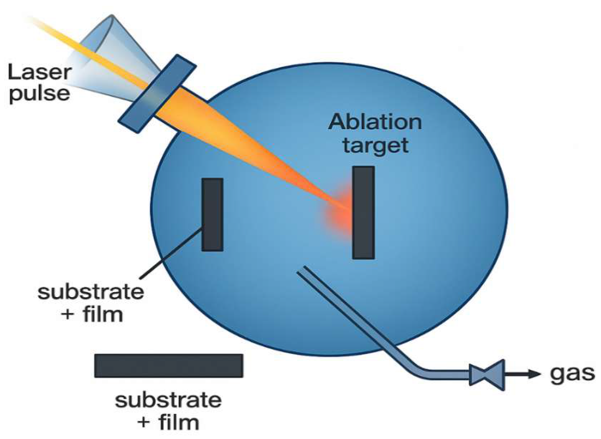
The pulsed laser deposition (PLD) method is widely used for research purposes to obtain thin-film structures of complex multicomponent oxides, in particular perovskite cathodes and buffer layers (
Figure 5). The essence of the method lies in the action of high-power laser pulses (most often a KrF excimer laser with a wavelength of 248 nm or a solid-state Nd:YAG laser) on the surface of a solid target, which leads to localized evaporation of the substance and the formation of a plasma plume containing atoms, ions, molecules, and clusters of the original material. The plasma plume propagates towards the substrate, where condensation of the particles occurs, forming a thin-film coating. Depending on the nature of the target and the atmosphere in the working chamber (vacuum, argon, oxygen, nitrogen), both physical and reactive deposition are possible [
76].
Sangbong Ryu et al. [
77] studied a BaCo
0.4Fe
0.4Zr
0.1Y
0.1O
3–δ (BCFZY) cathode material deposited by pulsed laser deposition (PLD) on ScSZ electrolyte. The resulting 220 nm thick film had a nanoporous structure favorable for enhancing the cathode activity. X-ray diffraction analysis confirmed the preservation of the perovskite structure, and SEM/EDS confirmed the uniform distribution of the components. The cell with the BCFZY cathode exhibited an open-circuit voltage of 1.12 V at 500 °C, indicating high electrochemical activity. This work demonstrates the potential of PLD for creating efficient thin-film cathodes for IT-SOFCs.
Xu et al. [
78] present the current state-of-the-art in applying pulsed laser deposition (PLD) to form thin-film IT-SOFC components. The focus is on cathodes, electrolytes, buffer layers, and interfacial interfaces. PLD enables the formation of dense and nanostructured films with high stoichiometric accuracy and good adhesion without the need for high-temperature annealing. Cathodes formed with a vertically oriented nanoporous structure (e.g., BSCF) exhibit low polarization resistance (up to 0.09 Ω cm
2 at 750 °C). Electrolytes (YSZ, GDC, LSGM) with a thickness of <5 μm provide power densities up to 3 W/cm
2 and OCVs above 1.1 V. PLD-deposited buffer layers (e.g., SDC) significantly improve interfacial compatibility and enhance cell stability. The work highlights the potential of PLD as a versatile approach for creating efficient and stable next-generation multilayer SOFC structures.
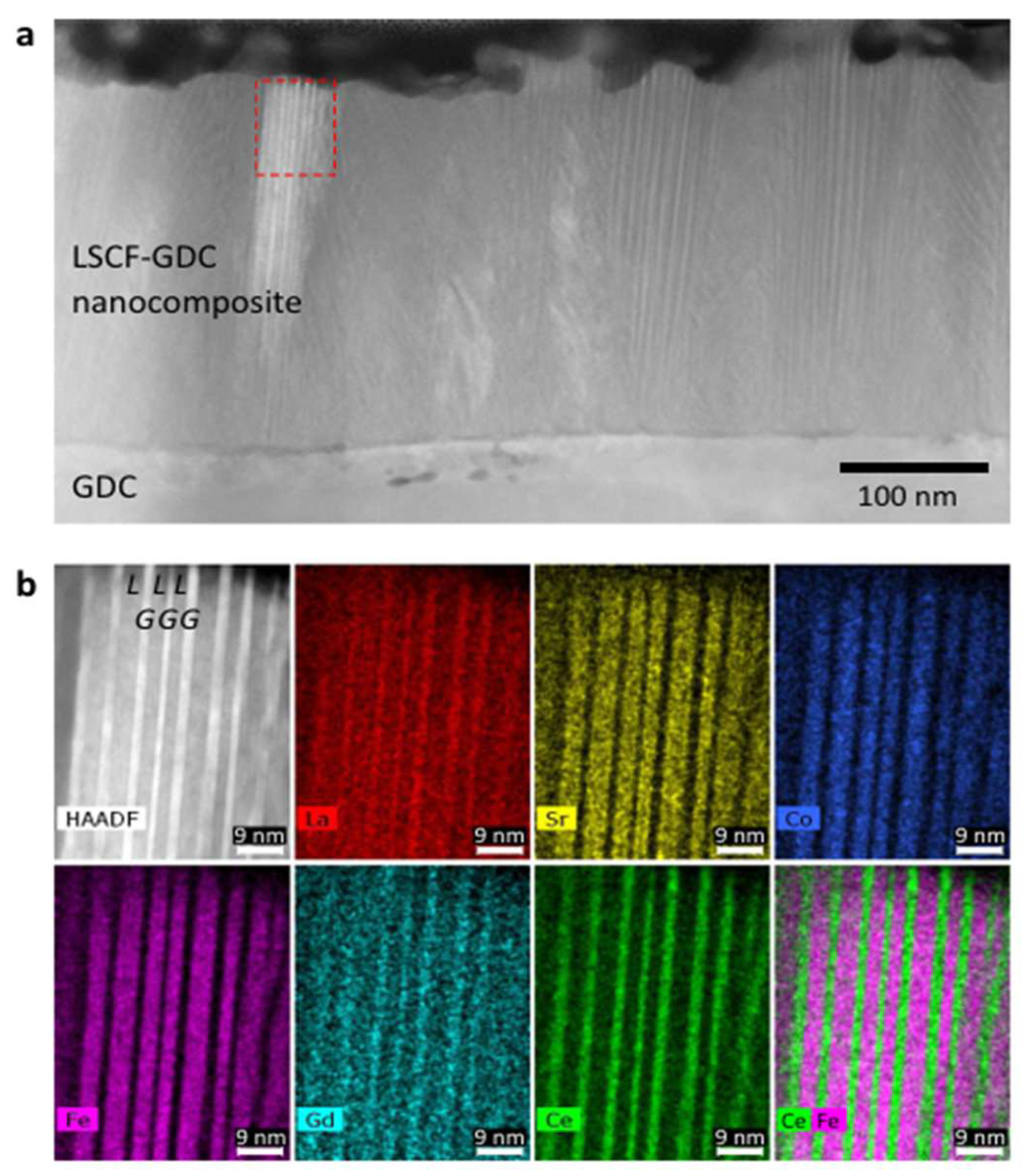
In the work of Develos-Bagarinao et al. [
79], an innovative cathode architecture for IT-SOFCs was presented, incorporating a nanoporous thin film of LSC (La
0.6Sr
0.4CoO
3–δ) and a self-assembled nanocomposite layer of LSCF–GDC, obtained by pulsed laser deposition (PLD). The nanocomposite layer of LSCF–GDC (~300 nm) has alternating nanobands of 2–5 nm width, forming an ordered structure with quasi-epitaxial boundaries. A nanoporous layer of LSC with a thickness of ~1 μm and high oxygen permeability was deposited on top of it. In the composite architecture on the anode-support cell (NiO–YSZ/YSZ/GDC/LSCF–GDC/LSC), an outstanding current density of 2.2 A/cm
2 at 650 °C and 4.7 A/cm
2 at 700 °C at a voltage of 0.7 V was achieved, which corresponds to a power density of 1.5–3.3 W/cm
2. At the same time, the polarization resistance was 0.030 Ω cm
2, and the ohmic resistance was 0.026 Ω cm
2 at 0.75 V (
Figure 6). The study showed that only the combination of the LSCF–GDC nanocomposite layer and nanoporous LSC provides the lowest resistance and the highest power. In addition, the cathodes demonstrated stable operation at 700 °C for more than 250 h. Thus, the proposed approach based on nanostructured PLD layers opens the way to the creation of highly efficient cathodes and next-generation architectures for SOFCs.
Despite its low productivity and limited coverage area, PLD remains an indispensable tool for studying phase transformations, epitaxial growth, and ionic conductivity of films. Experiments have successfully produced cathodes based on La
2NiO
4, La
0.6Sr
0.4CoO
3, and even gradient structures with controlled Sr content on the surface, opening the way to the formation of active zones with minimal resistance [
79].
3.2.3. Atomic Layer Deposition (ALD)
Atomic layer deposition (ALD) is a unique technology that provides atomically precise control of layer thickness and composition, even on topologically complex substrates. ALD is particularly valuable for depositing buffer, diffusion, and sealing layers, as well as ultrathin electrolytes (<100 nm) with high density (
Figure 7) [
80]. In recent years, work has intensified on the use of ALD to create interface layers at the electrode/electrolyte interface, which improve stability, prevent Sr diffusion, and reduce contact resistance. An example is the deposition of Al
2O
3 or LaPO
4 nanofilms with a thickness of 5–20 nm, demonstrating improved interfacial characteristics without significantly affecting the overall conductivity of the system [
81].
ALD has emerged as a powerful technique for nanoscale interface engineering within SOFC architectures, enabling precise control of surface chemistry, composition, and microstructure at sub-nanometer resolution. Recent advances demonstrate that ALD-derived thin films can significantly enhance electrochemical performance, long-term stability, and degradation resistance of both electrodes and electrolytes. For example, the deposition of doped CeO
2 onto perovskite cathodes via ALD has been shown to boost the oxygen reduction reaction (ORR) kinetics and reduce polarization losses in symmetrical SOFC configurations, highlighting the ability of ALD to create highly active and chemically stable nano-interfaces [
82]. Earlier studies also revealed that ALD can effectively stabilize nanostructured cathodes by forming conformal, ultrathin protective layers that suppress grain coarsening and maintain high electrochemically active surface area during operation [
83]. Furthermore, ALD has been applied to finely tailor the microstructure and catalytic functionality of perovskite cathodes, achieving optimized reaction pathways and improved interfacial transport properties through atomic-scale composition tuning [
84]. Overall, these findings confirm that ALD represents a versatile and highly effective strategy for modifying SOFC components, complementing traditional and thin-film fabrication routes by enabling precise surface engineering, defect control, and enhanced electrochemical robustness.
In this work [
85], an approach to increasing the activity of thin-film LT-SOFC anodes by modifying a porous Pt anode with an ultrathin CeO
2 layer deposited by the ALD method was proposed. The <10 nm thick coating formed a dense Pt–CeO
2 interface with a high Ce
3+ content (55%), contributing to an increase in the density of HOR active sites and improving ion transport. This resulted in an 86% decrease in activation resistance (from 1.10 to 0.16 Ohm cm
2) and an increase in the peak power density to 478 mW/cm
2 at 450 °C, which is 2 times higher than that of the unmodified anode. ALD modification also suppressed Pt agglomeration and preserved the porous morphology during heat treatment. However, the efficiency of the method is limited in the case of dense anodes due to poor CeO
2 penetration. The work confirms the high efficiency and stability of the ALD modification of anodes and its potential for low-temperature SOFCs.
In this work [
86], a method for determining the minimum thickness of an ALD-deposited YSZ blocking layer is presented taking into account the microgeometry of porous substrates such as anodic-oxidized aluminum (AAO). It is found that variations in pore diameter (36–207 nm) and wall tilt angle (9–79°) significantly affect the formation of a hermetic sublayer beneath the GDC electrolyte. At a YSZ thickness of 60 nm, the average OCV value was 1.03 V, while at 120 nm it reached 1.13 V, close to the theoretical value. Simulation and FIB-SEM confirmed that for structures with large pores and a low tilt angle, at least 93 nm of YSZ is required to reliably block the electron current. This work highlights the importance of substrate geometry in the design of ultrathin layers and demonstrates the potential of ALD for the formation of dense, hermetic electrolytes in LT-SOFCs.
3.2.4. Chemical Vapor Deposition (CVD)
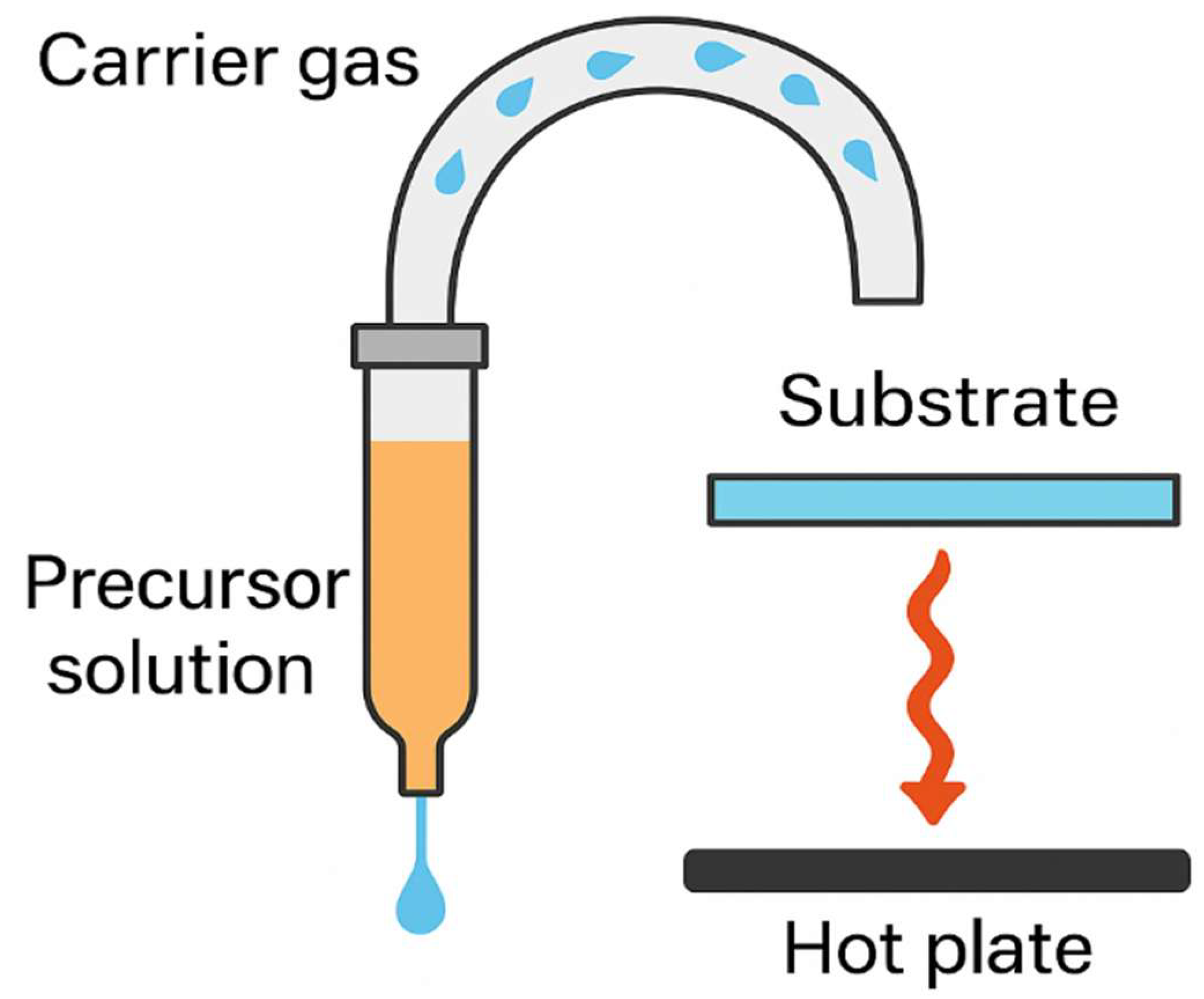
Chemical vapor deposition (CVD) allows the production of highly dense, uniform oxide films at temperatures below 800 °C (
Figure 8) [
87]. Despite its limited application in the field of SOFCs due to the difficulty of controlling multicomponent reactions, the method is used to deposit layers of ZrO
2, LaMnO
3, and other perovskite cathodes. Current research is aimed at implementing aerosol CVD [
88] and plasma-enhanced CVD (PECVD) [
89], which combine high coating uniformity and morphology control.
In this work [
90], a cathode based on nanoporous silver modified with an ultrathin GDC layer deposited by aerosol-assisted chemical vapor deposition (AACVD) was developed. The deposited GDC layers, 1.6–3.3 nm thick, uniformly covered the Ag surface without the use of vacuum, making the method a cost-effective alternative to ALD and PLD. The optimal composition (Ag-GDC0.5) provided a power density of 62.7 mW/cm
2 at 450 °C, comparable to a Pt cathode. The modification reduced both the ohmic and polarization resistance. Moreover, thicker layers (Ag-GDC5) demonstrated better thermal stability, preventing Ag agglomeration under long-term operating conditions. The work confirms the potential of AACVD for creating efficient and stable Ag-based cathodes approaching Pt-level performance, with the potential for scalable and low-cost production of IT-SOFCs.
In this paper [
91], a technology for depositing a dense thin-film YSZ electrolyte by the AACVD method for anode-supported SOFCs is presented (
Figure 9). Under optimal conditions (Y:Zr = 2:8, 450 °C), a crystallized layer 1 μm thick was formed without post-annealing. Cells with this electrolyte demonstrated an OCV >1 V and a power of up to 592 mW/cm
2 at 600 °C, which is 1.4–4 times higher than that of a reference cell with 8 μm YSZ deposited by screen printing. Impedance analysis showed a decrease in ohmic resistance by 4–5 times and polarization resistance by 3 times. The effect is due not only to a decrease in thickness, but also to improved interfacial contact due to the deposition features of AACVD. As the thickness decreased to 0.6 µm, a sharp drop in OCV (~0.5 V) was observed, due to a loss of film density. This study demonstrates the potential of AACVD as a vacuum-independent and scalable method for producing highly efficient thin-film electrolytes in IT-SOFCs.
3.2.5. Electrophoretic Deposition (EPD)
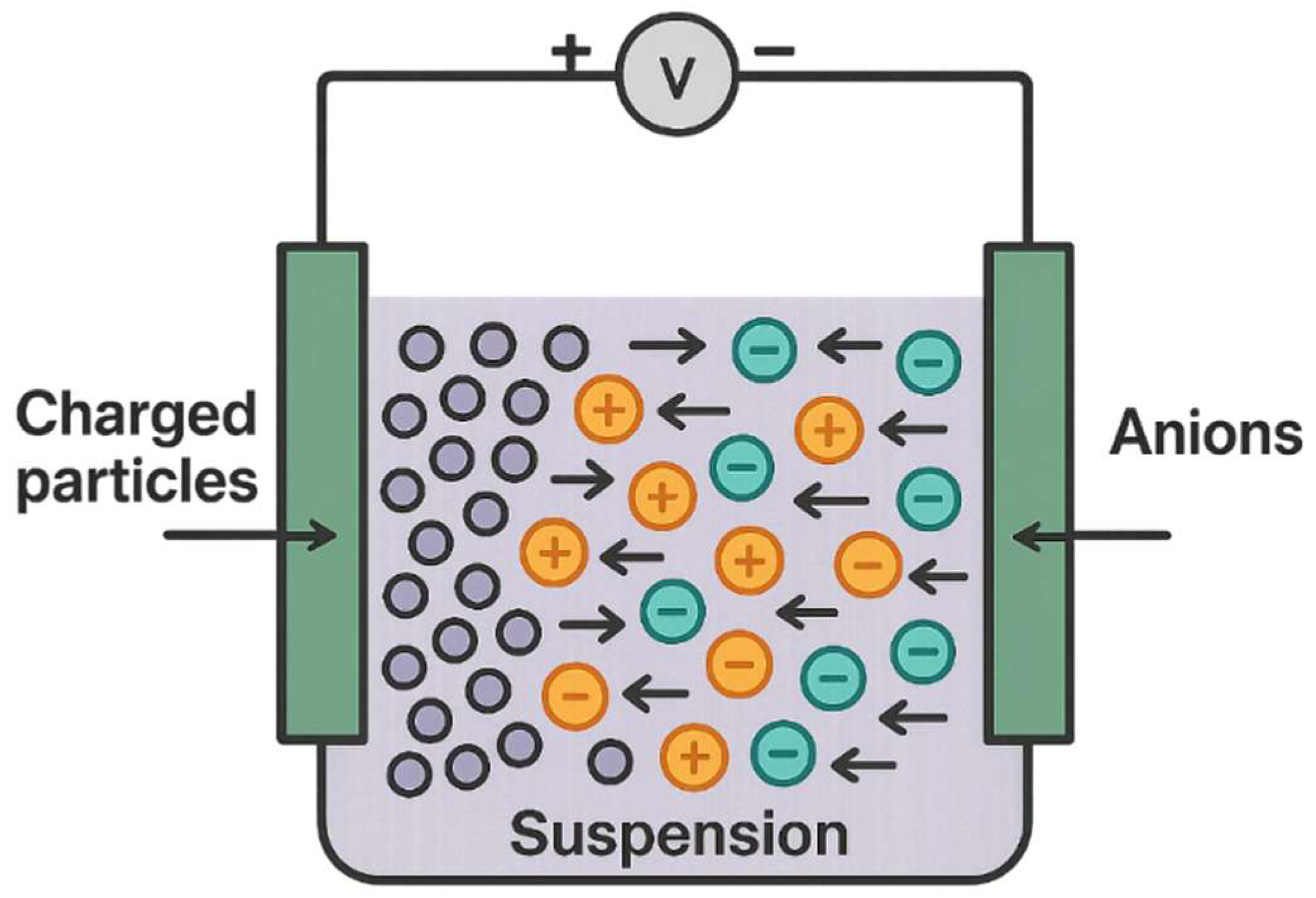
Electrophoretic deposition (EPD) is an electrochemical method in which charged particles in a suspension are transported and deposited on a substrate under the influence of an electric field (
Figure 10) [
92]. This approach is particularly suitable for producing porous anodes (e.g., NiO/YSZ) and cathodes (LSCF), as well as for depositing thick buffer layers. Modern modifications of EPD, including pulsed and localized deposition, allow for high reproducibility and density, bringing the method closer to the thin-film class [
93].
In this paper [
94], a comprehensive assessment of electrophoretic deposition (EPD) as a versatile and cost-effective method for forming thin-film coatings for SOFCs is presented. Both fundamental aspects (ζ-potential, electrical double layer, deposition kinetics) and practical issues, such as the choice of dispersion medium, suspension stabilization, and deposition on conducting and non-conducting substrates, are covered. EPD allows the formation of dense, porous, and multilayer structures with high speed (~1 μm/min) and good adhesion. The main limitations are suspension instability, outgassing in an aqueous environment, and deposit heterogeneity. Deposition models (Hamaker, Augustinik, Biesheuvel) and stability enhancement strategies, such as pH regulation, selection of additives (PEI, PAA, BMMA-5, I
2), and the use of alternating or pulsed current, are considered. The work highlights the potential of EPD in SOFC technology, provided that the slurry composition and deposition parameters are precisely controlled.
In [
95], direct electrophoretic deposition (EPD) of two-layer thin-film BCS-CuO/SDC electrolytes on NiO–BCS-CuO anode-supporting substrates was implemented for the first time. The addition of 5% SDC-lec nanopowder to micron-sized SDC-gn ensured a stable suspension (ζ-potential + 13 mV) and the formation of continuous coatings. Modification of the BCS-CuO suspension with iodine (0.4 g/L) made it possible to obtain dense layers with a thickness of 13–24 μm at 200 V. Selection of sintering temperatures (1450–1550 °C) ensured compatibility with the anode and suppressed Ba segregation. BCS-CuO/SDC electrolytes demonstrated an OCV of 0.95–1.05 V at 600–700 °C, significantly outperforming single-layer CeO
2 coatings (~0.7 V). This study confirms that bilayer electrolytes produced by layer-by-layer EPD effectively block electron conductivity and provide high ion current density, demonstrating the potential of this method for the scalable production of IT-SOFC composite electrolytes.
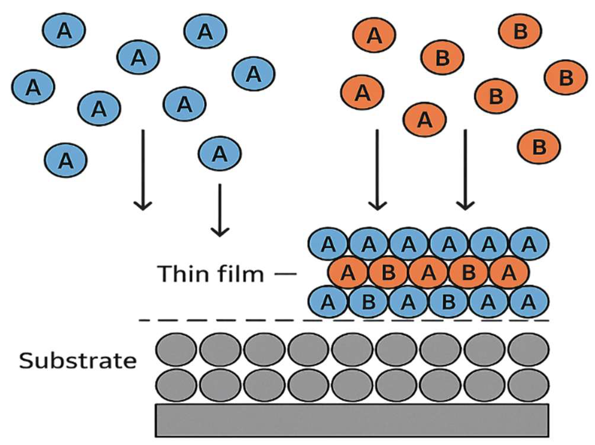
Thin-film deposition methods open up fundamentally new possibilities in the design of SOFCs [
96]. They enable the formation of multilayer architectures with combined functions (electrolyte + buffer + cathode), control of compositional and morphological gradients, the creation of nanostructured interfaces, and the integration of cells on flexible and metallic substrates, which are essential for transport and portable electronics. However, certain challenges remain before their large-scale industrial implementation, including:
The need to ensure high productivity while maintaining quality;
Reducing the cost of vacuum processes;
Developing new precursors and targets stable during deposition;
Controlling internal stresses and preventing cracking during thermal cycling [
97].
Thus, modern thin-film deposition methods are an integral element of the next generation of SOFC technologies, enabling precise tuning of all aspects of cell structure and properties. Their further development, including within hybrid production platforms, will play a key role in achieving high reliability, efficiency, and commercial appeal of SOFCs.
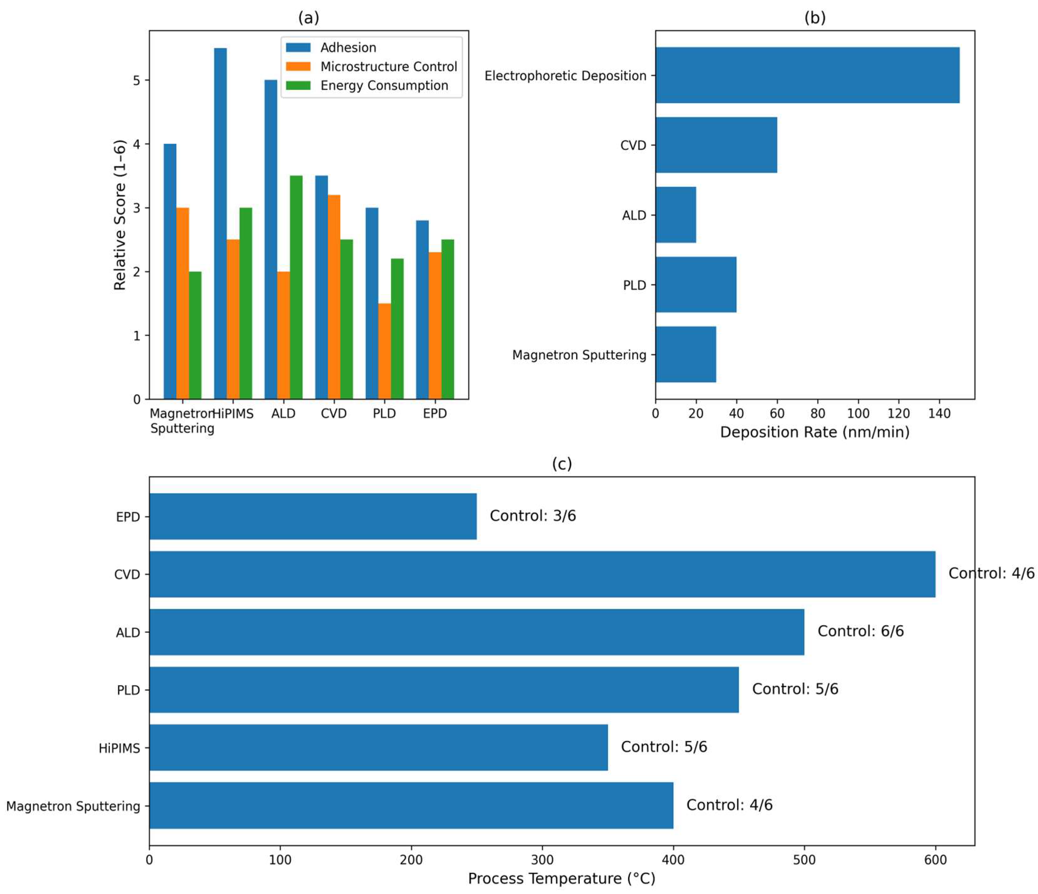
Based on a comprehensive comparative analysis of modern thin-film deposition methods, they are presented in the form of three thematic infographics (
Figure 11).
The infographic shows that magnetron sputtering (including HiPIMS) and pulsed laser deposition (PLD) methods provide high adhesion and structural homogeneity, but are characterized by significant energy consumption. Atomic layer deposition (ALD) demonstrates outstanding layer thickness control at low temperatures, making it particularly valuable for micro-SOFCs and systems on metal substrates, despite its low throughput and high equipment cost. Electrophoretic deposition (EPD), in contrast, is characterized by high deposition rates and minimal energy consumption, but is inferior in terms of structural control. Thus, neither method is universally applicable; each has its own optimal range of application. A rational choice of technology should be based on the SOFC architecture, processing temperature requirements, device geometry, and the productivity–precision–cost ratio. In this context, hybrid technological approaches, combining the advantages of several methods within a single manufacturing process, appear particularly promising.
This table (
Table 2) systematizes modern thin-film deposition methods used to form layers in SOFCs, depending on their architecture and operating temperature range. It distinguishes four main types of SOFCs: high-temperature planar cells, intermediate-temperature SOFCs (IT-SOFCs), metal-supported SOFCs (MS-SOFCs), and micro-SOFCs used in portable devices. For each type, the cell structural features, layer process requirements (such as thickness, density, porosity, and substrate compatibility), and the most suitable deposition methods are presented. Thus, for high-temperature SOFCs, traditional approaches such as tape casting and screen printing, followed by high-temperature sintering, are the most effective. IT-SOFCs require more precise methods, such as reactive magnetron sputtering, atomic layer deposition (ALD), and electrophoretic deposition (EPD). For metal substrates sensitive to high temperatures, low-temperature technologies are preferable: HiPIMS, ALD, and DC/RF modifications of magnetron sputtering. For micro SOFCs, precision, minimal thickness, and compatibility with flexible substrates are key—here, ALD, PLD, and PECVD are of the greatest importance.
Table 3 provides a comparative analysis of modern thin-film deposition methods for SOFCs, allowing for a quantitative and qualitative assessment of key parameters, as well as the suitability of each technology for specific applications. The parameters examined include operating temperature range, deposition rate, thickness and microstructure control, adhesion level, energy consumption, as well as the relative cost of equipment and the applicability of each method. The analysis showed that methods based on atomic precision control (in particular, ALD and PLD) offer the highest degree of control over film thickness and structure, which is especially important when forming interfaces, buffer layers, and ultra-thin electrolytes. However, they are characterized by low productivity and high equipment cost, limiting their use primarily to laboratory and prototype solutions.
Magnetron sputtering methods, including its pulsed and reactive modifications (HiPIMS, RF/DC sputtering), exhibit balanced characteristics in terms of deposition rate, structure control, and process temperature. They are recognized as the most versatile for forming both dense electrolytes and electrode layers on metal and ceramic substrates. Meanwhile, electrophoretic deposition (EPD) and CVD are of interest both for industrial production and for scalability. EPD is characterized by simplicity, low energy consumption, and high speed, but lacks precision in morphology control. CVD methods, in contrast, provide high quality but require significant temperatures and are costly.
Thus, the obtained data emphasize that the optimal choice of deposition method should be based on a balanced consideration of production requirements, precision, technological compatibility with materials, and economic feasibility. The combined use of various methods within a single process cycle can significantly improve the functionality and reliability of thin-film structures in modern SOFCs.
3.3. Additive Technologies
Additive manufacturing is a modern approach in materials science and engineering that involves the layer-by-layer construction of functional structures from a digital model [
120]. In the context of SOFC development, these technologies open up fundamentally new possibilities for designing geometrically complex, localized, functionally graded, and integrated structures with a high degree of precision, flexibility, and cost-effectiveness. Unlike traditional and thin-film methods, which primarily deposit continuous layers over the entire substrate surface, additive approaches allow the creation of a given structure directly during the deposition process, controlling both the composition and architecture of each layer [
121].
One of the key advantages of additive manufacturing is the ability to create hybrid structures in which several functional zones—anodic, cathodic, buffer, and electrolyte—can be simultaneously formed without the need for separate masking, etching, or subsequent mechanical processing [
122]. This significantly simplifies cell assembly, reduces the number of interphase boundaries and potential degradation zones, and shortens the process cycle. Furthermore, these technologies open the way to the development of customized and miniaturized SOFCs [
123], including microSOFCs [
123], flexible cells, and microenergy systems [
124].
3.3.1. Inkjet Printing
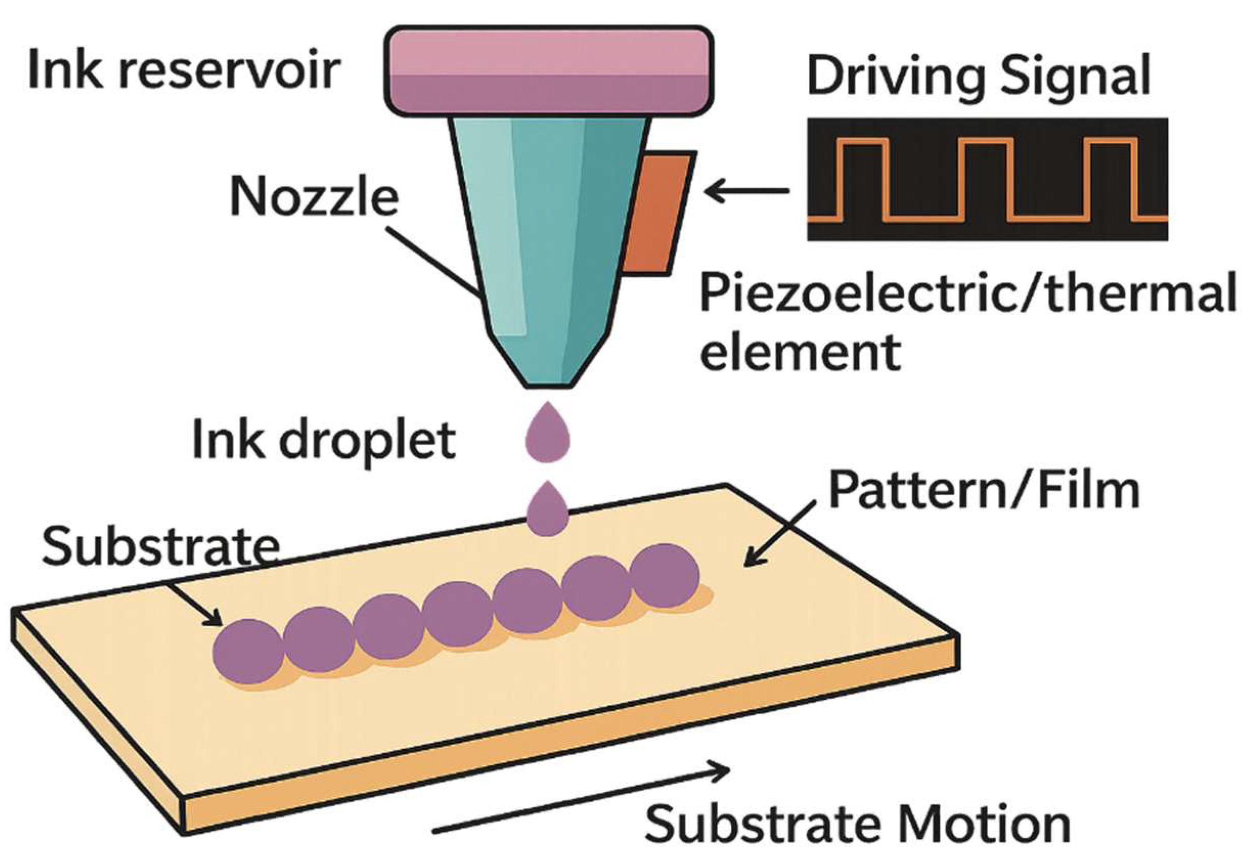
Inkjet printing is one of the most promising additive technologies, based on the measured, contactless deposition of microscopic droplets of liquid ink onto a substrate using thermal or piezoelectric heads (
Figure 12) [
125]. This method offers a unique combination of properties: high precision, digital control, minimal material loss, and compatibility with a wide range of substrates, including ceramic, metal, and polymer [
126]. In the context of SOFCs, inkjet printing is becoming an important tool for the formation of functional layers—anodes, cathodes, buffers, and even electrolytes—especially in small-scale, integrated, or hybrid devices [
127].
One of the key advantages of this technology is its high spatial resolution, reaching 20–50 µm, which allows for precise control of the geometry and placement of deposited materials. Unlike sputtering or extrusion methods, inkjet printing enables localized deposition without the need for masking, which is particularly important when forming complex architectures such as interconnects, gradient electrodes, or multi-zone cathode structures. Furthermore, the digital nature of the process allows for rapid adaptation of design solutions and the creation of customized prototypes without the need for equipment reconfiguration [
128].
Modern approaches in the field of inkjet printing of SOFCs include the use of modified inks with controlled rheology, nanostructured oxides (e.g., GDC, YSZ, LSCF) and organometallic precursors, the thermolysis of which allows the formation of pure oxide phases at low temperatures [
129]. To improve adhesion and prevent particle aggregation, stabilizers, surfactants and approaches to controlling pH and electrostatic interactions in the system are used [
130]. A number of studies [
131,
132] have shown that inks based on aqueous suspensions of GDC with a particle size of less than 100 nm can be successfully used to form buffer layers less than 1 μm thick with a high degree of uniformity, which makes inkjet printing competitive even with magnetron sputtering and CVD methods. LSCF-based cathode layers with high porosity and stable morphology after heat treatment at temperatures of 600–700 °C were also obtained.
In this paper [
133], a strategy for fabricating a thin-film anode-supported SOFC by inkjet printing was presented using a standard HP Deskjet printer and custom-designed inks based on NiO–YSZ, YSZ, GDC, and PBSCF nanopowders. The 0.8 μm thick YSZ electrolyte, printed in two passes, was characterized by high density and hermeticity, providing an OCV of 1.11–1.14 V and a peak power of 730 mW/cm
2 at 650 °C. The cell degradation was only 0.0002 V/h over 110 h, indicating its high stability. Impedance analysis revealed an ohmic resistance of 0.05 Ω cm
2 and low polarization resistance due to the nanoporous cathode structure. The work demonstrates that inkjet printing produces thin-film layer quality comparable to CVD and outperforms traditional methods in density and uniformity, offering a scalable and cost-effective approach to producing high-efficiency SOFCs.
Sanaz Zarabi Golkhatmi et al. [
134] developed stable LSCF (La
0.6Sr
0.4Co
0.2Fe
0.8O
3)-based inkjet-printable ink for deposition of cathodes in low-temperature SOFCs. Ink containing 3.5 wt% LSCF retained stable rheological properties for 6 months (Z-value from 2.77 to 3.45). Inkjet-printed cathodes demonstrated a significant decrease in resistance: R
ohm from 1.05 to 0.37 Ohm cm
2, R
3 from 6.09 to 1.43 Ohm cm
2 compared to samples deposited by the drop-casting method. SEM analysis revealed a uniform nanoporous morphology with an increased TPB zone and improved adhesion to the electrolyte. This study confirms that inkjet printing provides high electrochemical activity for cathodes and is a promising technology for scalable LT-SOFC production.
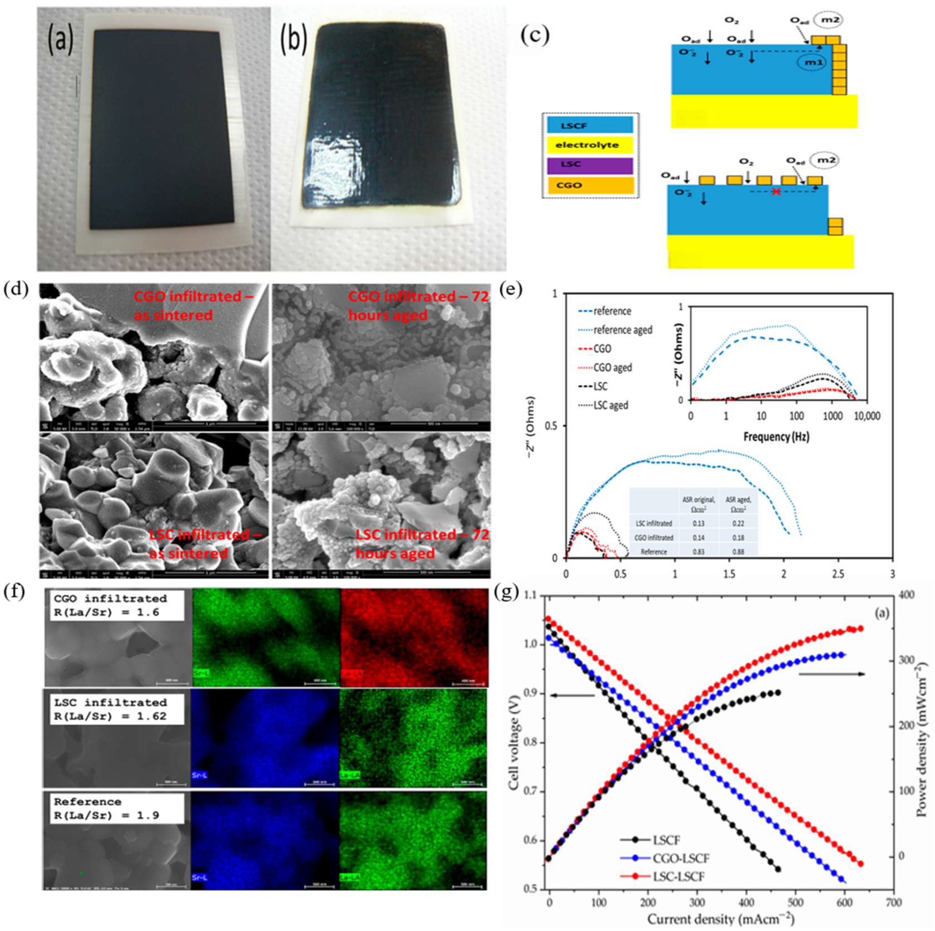
Eleonora Venezia et al. [
135] demonstrated the applicability of inkjet printing technology for nanoinfiltration modification of LSCF (La
0.6Sr
0.4Co
0.2Fe
0.8O
3–δ)-based cathodes in SOFCs. Two types of ink were used for functionalization: CGO (Ce
0.9Gd
0.1O
2–x) as an ionic conductor and LSC (La
0.6Sr
0.4CoO
3–δ) as a mixed ionic-electronic conductor. Infiltration was performed in a single step using an electromagnetic print head with droplets of 32–38 nL. The resulting nanocoatings provided a significant increase in the density of active sites participating in the oxygen reduction reaction. The electrochemical test results showed an increase in the peak power from ~250 mW/cm
2 (reference sample) to 310 mW/cm
2 (CGO) and 350 mW/cm
2 (LSC) at 700 °C. The polarization resistance decreased from ~1.6 to 0.6 Ω cm
2 (CGO, FASR = 2.7) and 0.4 Ω cm
2 (LSC, FASR = 4.0). CGO infiltration was also found to have a stabilizing effect: after 72 h, ASR degradation was only ~30% versus ~65% for LSC. SEM and EDX confirmed the uniform distribution of nanoparticles and the suppression of Sr segregation on the LSCF surface (
Figure 13). Thus, jet infiltration of CGO and LSC provides improvements in the electrochemical activity, stability and homogeneity of SOFC cathodes, while serving as a scalable and cost-effective alternative to traditional infiltration methods.
Compared to continuous deposition methods such as screen printing or spray coating, inkjet printing offers significant advantages in terms of precision, localization, the ability to deposit complex shapes, and reduced material consumption. Unlike thin-film methods (e.g., ALD and PLD), inkjet printing does not require high-vacuum equipment, meaning it has a lower capital cost and is more scalable [
136]. On the other hand, in terms of control over the thickness and density of the deposited layer, it is still inferior to ALD, especially when applying dense electrolytes with a thickness of less than 100 nm. Limitations of the technology include the need for careful tuning of ink properties, in particular viscosity (8–20 mPa·s), surface tension, and particle stability. Incorrect parameter selection can lead to unstable droplet generation, nozzle clogging, uneven coverage, or aggregation. In addition, to obtain a functional layer with a given structure, post-processing is required—most often thermal sintering in the range of 400–800 °C, which limits the application on sensitive or polymer substrates [
137].
Nevertheless, thanks to rapid advances in the development of functional inks, optimization of printing conditions, and combination with low-temperature processing (e.g., microwave or laser curing), inkjet printing is firmly positioned as a key future technology for compact and integrated SOFCs. Its significance is particularly high in applications involving metal substrates, hybrid architectures, flexible media, and microscale systems, where traditional methods are either technically inapplicable or economically unfeasible.
3.3.2. Three-Dimensional Printing (Direct Ink Writing, DIW)
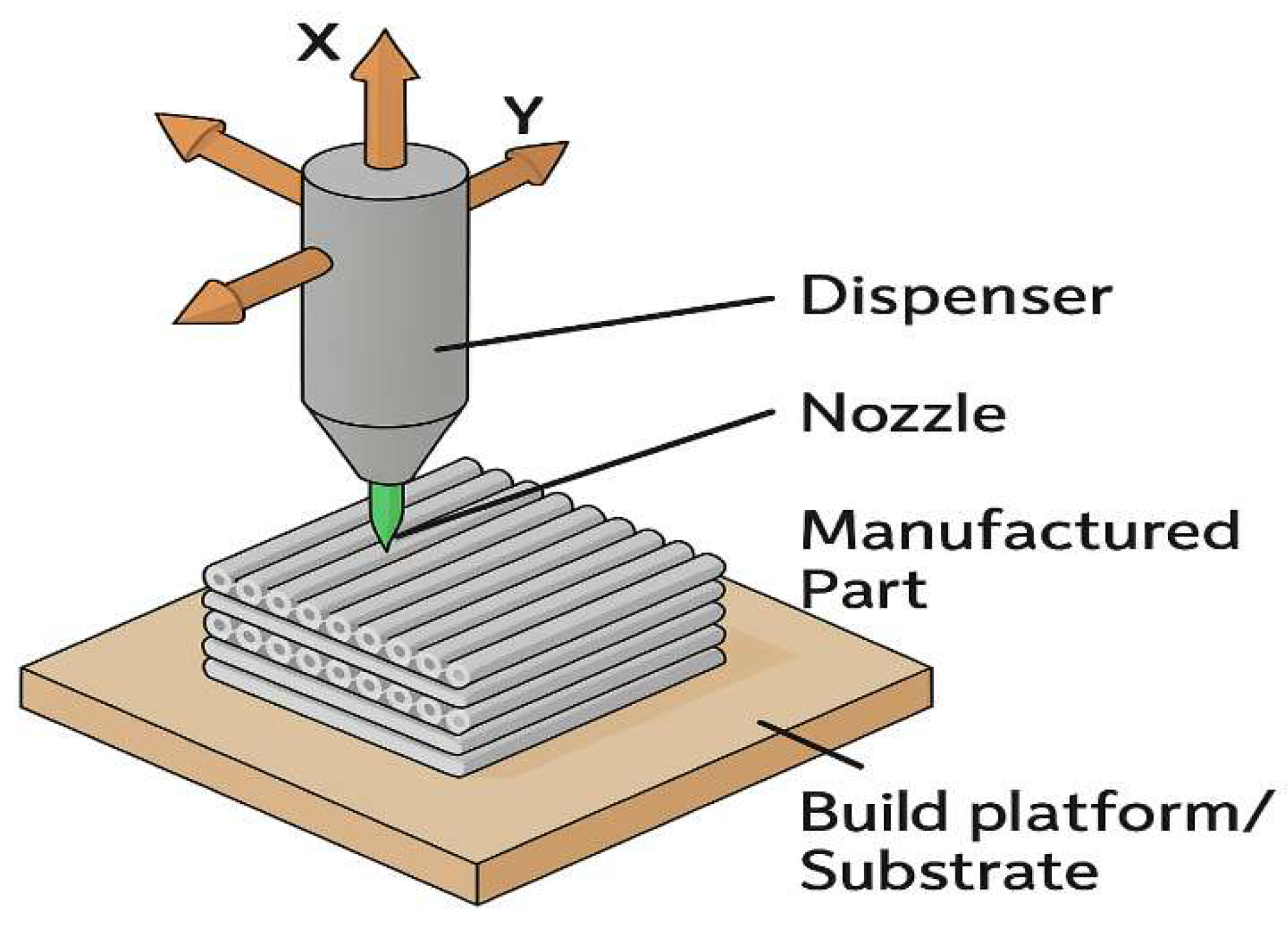
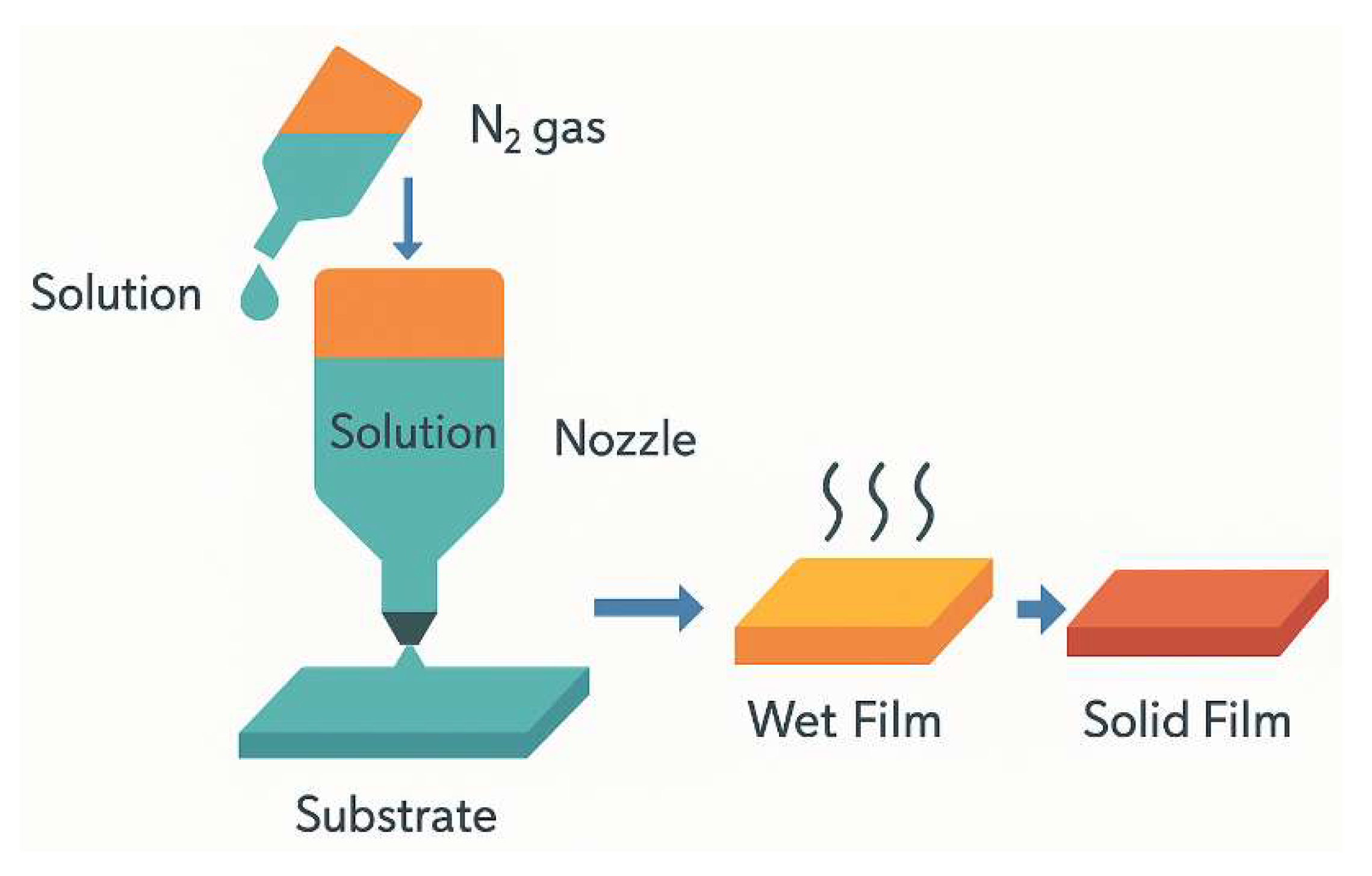
Direct Ink Writing (DIW) 3D printing is one of the most flexible and powerful additive methods for forming three-dimensional ceramic structures applicable to SOFC design (
Figure 14) [
138]. The principle of the method is based on the controlled extrusion of highly viscous inks (pastes) through a micro-nozzle along a pre-programmed trajectory, followed by drying and heat treatment [
139]. Unlike inkjet printing, which primarily forms thin layers, DIW allows for the creation of full-size three-dimensional elements with an architecture adapted to specific functional requirements. In recent years, the greatest attention has been paid to the use of DIW for the fabrication of supporting anode substrates, structured cathodes, porous interlayer connections, and even complete monolithic fuel cells. The ability to design the internal structure of pores (size, shape, direction) makes it possible to optimize the transport of mass and gas, as well as to expand the active surface involved in the electrochemical reaction [
140].
In this work [
141], the feasibility of using 3D inkjet printing (Direct Ink Writing, DIW) technology to form an anode (NiO–ScSZ) and cathode (LSM) in a large-format SOFC cell measuring 5 × 5 cm
2 was demonstrated. Optimization of the ink (viscosity of 5.85 Pa·s for the anode and 0.97 Pa·s for the cathode) ensured the formation of uniform and reproducible layers. Additional deposition of electrolyte and anode functional layer by spray and spin coating methods allowed achieving a power of 368 mW/cm
2 at 800 °C. The introduction of a hybrid ScSZ layer on AFL using spray deposition and reactive magnetron sputtering increased the productivity to 442 mW/cm
2 (an increase of 21%) and reduced the polarization resistance to 0.267 Ohm cm
2. In long-term testing at 700 °C (0.5 A/cm
2, 100 h), the cell demonstrated stability with a voltage drop of 0.845%/h and also demonstrated good thermomechanical stability in the 400–700 °C range. This work confirms the potential of DIW as a scalable and reliable method for producing high-efficiency SOFCs.
Manasa Kumar Rath et al. [
142] developed a large-format (5 × 5 cm
2) solid oxide fuel cell using 3D inkjet printing (DIW) technology to deposit the anode (NiO–ScSZ) and cathode (LSM), and realized a multilayer architecture with a GDC/ScSZ hybrid electrolyte. The electrolyte and anode-functional layer were further formed by spray and spin coating methods, and the dense ScSZ layer was formed by reactive magnetron sputtering. Optimization of the ink yielded a viscosity of 7.53 Pa·s (anode) and 0.97 Pa·s (cathode), which contributed to the formation of a strong, porous structure. The base cell (3DC) achieved a power of 368 mW/cm
2 at 800 °C, while the modified cell (MS-3DC) with an ScSZ interlayer insert showed a 25% increase in power to 460 mW/cm
2, with a decrease in polarization resistance to 0.296 Ω cm
2. EIS and DRT analyses confirmed that the ScSZ layer acts as an electron-blocking barrier, reducing AFL microporosity and improving contact with the GDC. The cell demonstrated stable operation at 0.5 A/cm
2 for 100 h (voltage drop 0.845%/h) and withstood 18 thermal cycles (400–700 °C) without degradation. Microstructural analysis showed the absence of delamination and interlayer diffusion. The work confirms that the combination of DIW and magnetron deposition of protective layers provides high efficiency, reliability and scalability potential for SOFC technology.
The pastes used in DIW are compositions based on ceramic powders (NiO, YSZ, CGO, LSCF, etc.), organic binders, and solvents that provide thixotropic behavior: high viscosity at rest and shear-decreasing viscosity [
143]. This rheology allows the paste to flow through the nozzle during printing but retain its shape after exiting, which is especially important for maintaining complex geometries. Modern inks include additives that regulate drying, green body strength, and sintering shrinkage. Comparison with other deposition methods shows that DIW has unique advantages in terms of architectural freedom, structural integration, and manufacturing flexibility. Unlike tape casting and screen printing, DIW does not require molds or templates, is easily programmed for varying geometries, and can be used to produce cells with customized characteristics. At the same time, in terms of deposition accuracy and thickness control, DIW is inferior to thin-film deposition methods such as ALD and magnetron sputtering, but surpasses them in terms of the volume of deposited material and the ability to create macrostructured layers [
144].
Recent studies [
145] demonstrate that DIW can successfully form NiO/YSZ anode substrates with graded porosity, providing a stable transition from a macroporous support to a dense functional interface with the electrolyte. Fuel cells with printed cathode layers based on LSCF and layered GDC/YSZ electrolyte architectures have also been demonstrated. Combining this with laser or microwave post-processing allows for reduced sintering time and avoids overheating of the entire structure.
DIW demonstrates exceptional potential for digital SOFC manufacturing, particularly in projects requiring a combination of functional integration, pore architecture optimization, rapid prototyping, and waste minimization. Combined with other methods such as reactive sputtering or ALD, 3D printing can be used to form support layers and subsequently deposit thin-film functional coatings, paving the way for the creation of next-generation multiscale and multilayer fuel cells [
146].
3.3.3. Aerosol Jet Printing
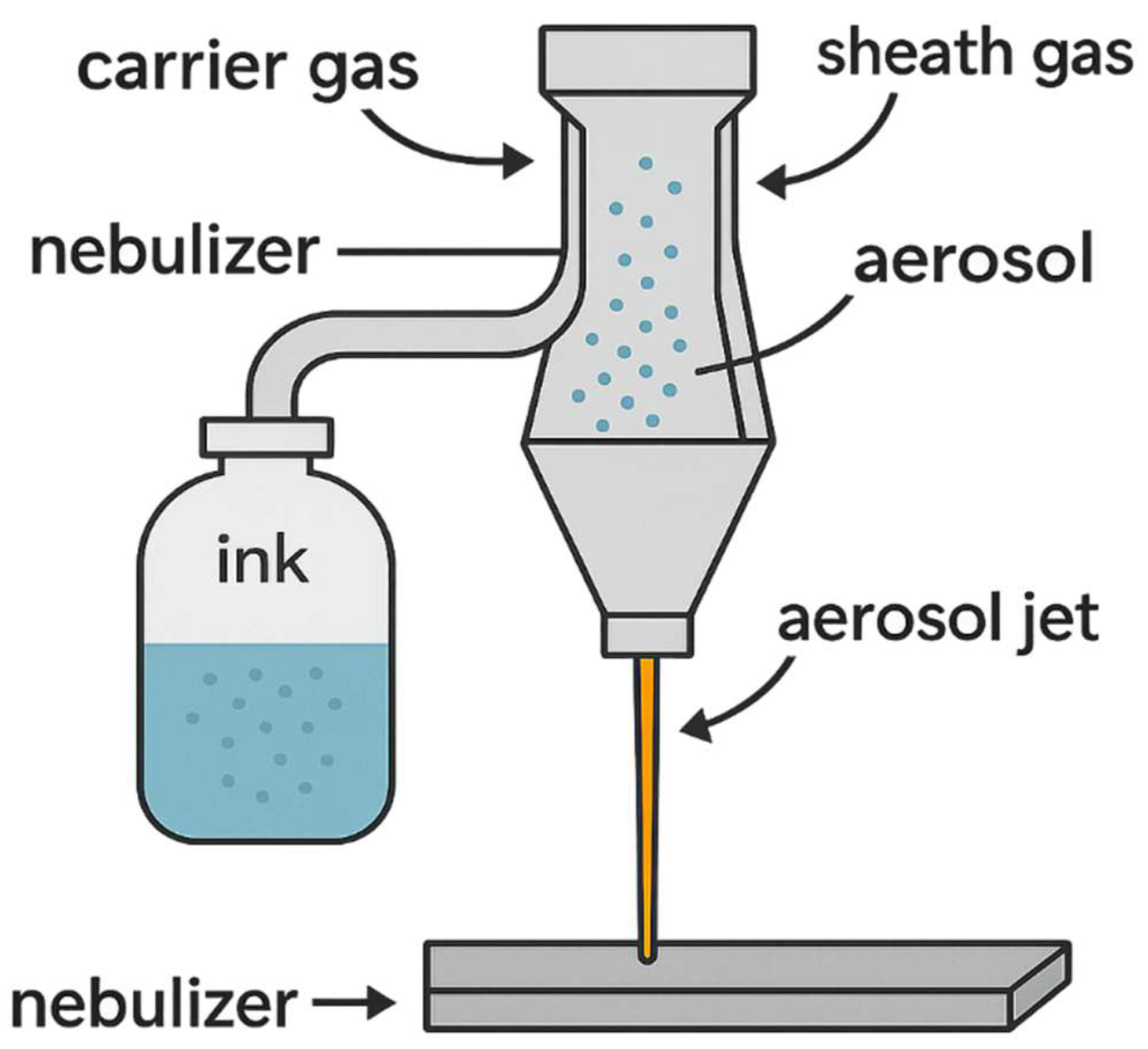
Aerosol Jet Printing (AJP) is a high-precision additive material deposition method that uses aerosol ink transported by a gas flow and focused onto the substrate surface in the form of a narrow jet (
Figure 15) [
147]. Unlike inkjet printing, aerosol technology allows for the deposition of materials with a higher solid phase content, with high resolution (5–50 μm), while remaining contactless and applicable to surfaces of various geometries—from flat to three-dimensional and flexible [
148]. The technology is based on ultrasonic or pneumatic atomization of a suspension containing functional particles (e.g., YSZ, CGO, LSCF, Pt, Ag), followed by the transport of aerosol droplets to the substrate. The system nozzle forms a narrowly directed stream, which allows for the deposition of materials with high accuracy and repeatability. The use of a carrier (usually nitrogen or air) and a focusing gas allows for variation in layer thickness, line width and application speed [
149].
Mary Sukeshini A. et al. [
150] investigated the application of Aerosol Jet Printing (AJP) technology for the formation of a functionally graded NiO/YSZ anodic interlayer in anode-supported SOFCs. A dual-atomizer system with online ink mixing was implemented for the first time, providing variation in the layer composition by thickness from 50:50 to 17:83 wt.% NiO/YSZ. The graded interlayer was applied in 12 passes, compared with a uniform layer of the same thickness (35 μm). At 850 °C, the graded structure provided a power density of 235 mW/cm
2, versus 200 mW/cm
2 for the non-gradient version. Microstructural analysis (LV-SEM) showed a uniform phase distribution, with an increase in the proportion of YSZ near the boundary with the electrolyte, which reduces the ohmic resistance and prevents the formation of excess electronic conductivity. The work demonstrated the high precision, reproducibility, and flexibility of AJP for forming thin, graded structures with controlled architecture, opening the prospect of scalable production of multilayer SOFC elements.
The authors of [
151] investigated the use of Aerosol Jet Printing (AJP) technology for the formation of electrolyte and cathode layers in SOFCs. Using a dual atomizer, separate inks based on YSZ and LSM were supplied and mixed directly in the printing zone. The inks were stabilized in an organic butanol–terpineol system with the addition of a copolymer providing dispersibility and stability. Microstructural analysis (LV-SEM, 1 kV) showed that the printed YSZ electrolyte has a dense structure and a thickness of 33–35 μm, while the composite LSM/YSZ cathode interlayer was porous (~11 μm), and the LSM current collector layer was dense (~4 μm). An attempt was also made to create a composite LSCF cathode with an intermediate GDC buffer layer; however, the current state of GDC ink requires further development. The paper highlights the potential of AJP as a precise and reproducible technology for layer-by-layer formation of multicomponent structures in SOFCs with controlled microstructures and the ability to print complex architectures without the use of masks or vacuum systems. Particular attention is paid to the potential of AJP for the creation of composite cathodes and buffer layers, which contribute to increased efficiency and reliability of IT-SOFCs.
Recent studies demonstrate that layers produced by AJP can exhibit high electrochemical activity and good adhesion during post-processing at temperatures of 500–700 °C [
152]. For example, printed LSCF-based cathodes with controlled porosity exhibit polarization resistance values comparable to those produced by screen printing or magnetron sputtering. Furthermore, cases of the formation of thin CGO layers <500 nm thick with high density have been demonstrated, making AJP a promising technology for buffer interfaces and protection against interfacial degradation [
153].
3.3.4. Suspension Printing and Spray Coating (Spray Coating)
Suspension printing and spray coating are simple and scalable additive material deposition methods based on spraying liquid suspensions containing functional particles onto a substrate surface to form continuous or porous coatings (
Figure 16) [
154]. These technologies have become widely used in the field of ceramic and functional oxide materials, including applications in SOFCs, where they are used to deposit cathodes, buffer layers, protective coatings, and, in some cases, electrolytes. The essence of the method is that a suspension (water- or organic-based) containing the target ceramic phase (e.g., LSCF, YSZ, GDC, LaNiO
3, etc.) is sprayed using a nozzle—mechanical, pneumatic, ultrasonic, or plasma. Control of spray parameters (flow rate, pressure, distance to the substrate, temperature, travel speed) allows the formation of coatings with a given thickness (from hundreds of nanometers to tens of micrometers), texture and morphology [
155].
Kang Xu et al. [
156] developed a cost-effective spray-deposition method for forming LSCF-based cathodes in SOFCs, providing improved electrochemical performance and durability. At 750 °C, the interfacial polarization resistance of symmetric cells was 0.059 Ω cm
2, which was 34% lower than that of screen-printed cathodes. DRT analysis showed a decrease in resistance in the mid- and low-frequency ranges, indicating improved surface exchange and mass transport processes. Spray-deposited cathodes showed high stability: after 100 h at 700 °C, their structure remained unchanged, whereas screen-printed cathodes exhibited aggregation and a 32.4% increase in resistance. In anode-supported cells, the power with a cathode deposited using the spray-deposited method reached 1.012 W/cm
2 at 750 °C, compared to 0.713 W/cm
2 for the screen-printed counterpart. Long-term testing (700 °C, 0.5 A/cm
2, 70 h) showed only a slight increase in resistance (Rp: from 0.275 to 0.311 Ohm cm
2), confirming the structural stability. This study demonstrates that spray-deposited technology is a scalable and technologically simple alternative, providing high ORR activity, low resistance, and cathode stability under long-term SOFC operation conditions.
In [
157], the efficiency of spray deposition as an accessible and reliable method for depositing a Ce
0.9Gd
0.1O
1.95 (GDC) electrolyte layer on NiO–GDC mini-tubular anodes for SOFC fabrication was demonstrated. The morphology and thickness of the GDC films were studied as a function of the number of deposition cycles using optical and scanning electron microscopy, and the phase compatibility of the anode and electrolyte was confirmed by X-ray diffraction (XRD) analysis. A cathode layer based on porous LSCF–GDC was deposited in a similar manner. The fabricated miniature tubular cell with the NiO–GDC/GDC/LSCF–GDC configuration demonstrated a maximum power density of 0.510 W/cm
2 at 600 °C when operating on humidified hydrogen and air. The results confirm the high potential of the spray deposition method as an industrially scalable, low-cost approach to the formation of both dense electrolytes and porous cathodes in SOFC designs.
In SOFC technology, the method has proven itself particularly successful in the deposition of LSCF and LSC-based cathode layers on YSZ or CGO electrolyte substrates [
158]. It is also actively used to form CGO buffer layers or protective barriers against Sr and Cr diffusion [
159]. The scientific literature contains data on the deposition of GDC and LSGM layers using spray coating followed by sintering, which provides a density sufficient for use as electrolytes in IT-SOFCs [
160]. Modern modifications of the method include the use of ultrasonic sprayers, which allow for more uniform particle dispersion and a finer layer structure, as well as the use of plasma treatment in a jet for instantaneous drying and partial sintering in real time. These approaches make the method particularly relevant for hybrid deposition technologies, where spray coating is used as a preliminary step before thin-film deposition or as a method for creating a sublayer with controlled morphology [
161].
3.3.5. Microextrusion
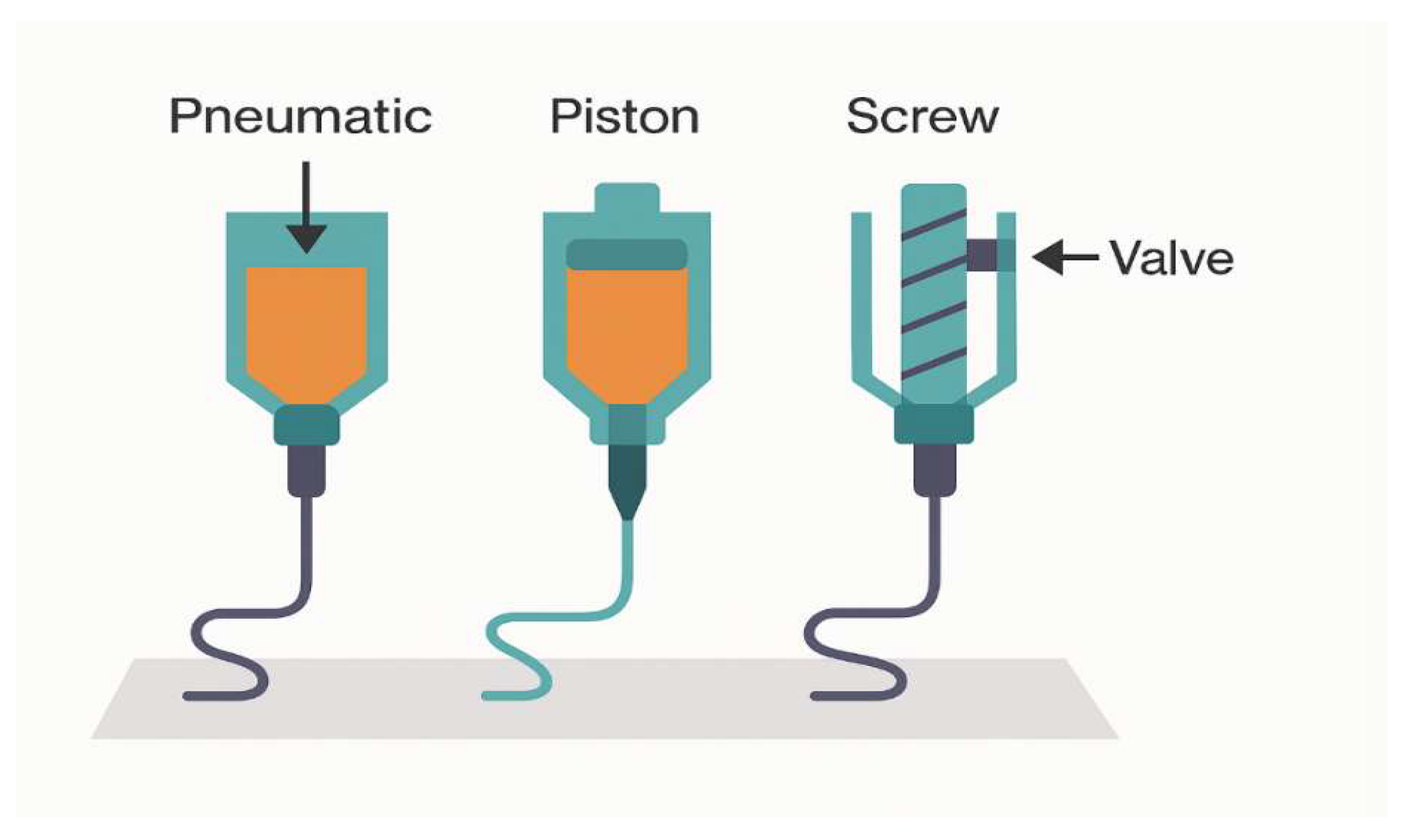
Microextrusion is an additive manufacturing method based on the measured extrusion of a highly viscous paste or ink through a micro-nozzle to form continuous or discrete structures of a given geometry (
Figure 17) [
162]. Unlike traditional 3D printing (DIW), microextrusion is focused on the high-precision creation of elements with a small cross-section, high line density, and the ability to locally deposit functional layers. This method confidently occupies an intermediate position between extrusion and inkjet printing methods, combining the advantages of volumetric material feed with precise geometric accuracy [
163].
Haewon Seo et al. [
164] used microextrusion printing to increase the anode–electrolyte interface area in anode-supported SOFCs to improve the electrochemical efficiency. The developed mathematical model allowed for accurate prediction of the width of the deposited structure taking into account the paste contact angle, which was confirmed experimentally. Three types of cells were fabricated: a reference cell (Cell REF) and cells with an increased interface area by 7% (Cell 40) and 13.5% (Cell 80). At 600 °C and a current load of 0.3 A/cm
2, the cells demonstrated a significant increase in voltage: 0.49 V (REF), 0.62 V (Cell 40), and 0.72 V (Cell 80). Impedance analysis showed a decrease in the total resistance from 2.5 to 1.4 Ω cm
2. The effect was particularly pronounced at high H
2 concentrations (80%) and lower temperatures. The increased productivity is explained by both the increased active area and localized changes in electrolyte thickness, which facilitate improved ion transport. This study demonstrates that microextrusion printing is a promising additive technology for forming architectures with enhanced interfacial interactions and can be effectively applied even with traditional materials.
The authors of [
165] presented an innovative strategy for modifying the anode–electrolyte interfacial contact in anode-supported SOFCs using temperature-controlled microextrusion 3D printing. The formation of mesostructured relief anodes (10–100 μm pitch) allowed increasing the interfacial interaction area by up to 25% compared to a flat configuration. Controlling the substrate temperature (from 30 to 5 °C) ensured an improved height-to-width ratio of the ridges (from 0.61 to 0.98), contributing to geometric stability and deposition uniformity. Electrochemical tests showed that the modified cell achieved 0.44 W/cm
2 at 600 °C, which is 2.1 times higher than that of a flat cell (0.21 W/cm
2) and 30% higher than that of an unmodified relief structure. Simulation confirmed a 10.1% reduction in ohmic overpotential and a 7.5–10.5% reduction in activation overpotential, with a slight increase in concentration overpotential (1.9 mV). The study emphasizes that temperature-controlled microextrusion enables precise design of anode mesostructures, increases the active area, and improves the electrode characteristics of SOFCs, while demonstrating potential for scalability and applicability in industrial production.
One of the key advantages of the method is the ability to precisely control the volume of deposited material, making it effective for depositing layers with thicknesses ranging from 5 to 200 μm and line widths ranging from 50 to 300 μm [
166]. The inks and pastes used typically contain ceramic powders (e.g., NiO/YSZ, LSCF, CGO) with the addition of rheological modifiers and organic binders to ensure flow stability and shape retention after application. A distinctive feature of microextrusion is the need for high thixotropy of the paste—the viscosity must decrease sharply under shear in the nozzle, but recover quickly after exiting to maintain shape retention [
167].
Recent studies have shown that microextrusion can be used to produce porous NiO/YSZ-based anodes with an optimal pore size/distribution ratio and high mechanical strength after sintering. Successful deposition of LSCF and GDC layers on complex-shaped substrates using thermally activated pastes that provide high adhesion and chemical compatibility has also been reported [
168]. Microextrusion has high potential in both research and production practice, especially in combination with other deposition methods. It can be used as a basic tool for forming load-bearing or functional sublayers onto which thin-film coatings are subsequently applied (e.g., by magnetron sputtering or ALD), thus forming hybrid structures of high complexity and technological reliability [
169].
A comparative analysis of additive methods for layer formation in SOFC technology, presented in tabular form (
Table 4), allows us to highlight the functional features and applicability of each approach depending on technological tasks, requirements for resolution, layer thickness, rheological properties of the inks used, and the nature of the target application.
Inkjet printing offers the highest resolution of all the methods considered and is ideal for forming thin buffer layers and point electrodes. However, it requires strict ink parameters (low viscosity and stable dispersion), which can limit material composition. Direct inkjet printing (DIW) and microextrusion offer similar capabilities for working with high-viscosity pastes and are the methods of choice for creating support anodes and macrostructured interconnects. DIW enables the creation of three-dimensional architectures, while microextrusion allows for thinner, more localized structures with high geometric stability.
Aerosol jet printing offers an outstanding combination of high precision, compatibility with 3D substrates, and flexibility in ink viscosity. This makes it particularly promising for micro-solid-fuel cells, precision barrier layers, and electrochemical interconnects. However, the high cost of equipment and the need to control aerosol stability limit its widespread industrial adoption. Suspension printing and spray coating offer a cost-effective solution for large-scale deposition of cathodes and buffer layers. They are particularly effective in applications where uniform coating over large areas is a priority, but they lack precision and microstructure control compared to more precise methods.
Overall, the table confirms that no single method is universally applicable: their selection should be based on an analysis of layer requirements (thickness, density, structure), substrate type, cell configuration, and target production scale. The optimal approach is hybridization—a combination of high-precision methods for interface layers (Inkjet, AJP) with volumetric methods for support and structural components (DIW, Spray, Microextrusion).
The table below summarizes recommendations for selecting additive technologies for depositing functional layers based on SOFC architecture (
Table 5). It systematizes the key technological requirements for different cell types—IT-SOFC, MS-SOFC, and micro-SOFC—and identifies the methods that best meet these requirements, taking into account geometry, thermal stability, precision, and compatibility with substrate materials.
For IT-SOFCs, where electrolyte density and interface compatibility at moderate temperatures (600–800 °C) are critical, inkjet printing for buffer layers, spray coating for cathodes, and microextrusion for anode formation are preferred. For MS-SOFCs, due to the limited processing temperature (<600 °C) and the need to deposit dense layers on metal substrates, Aerosol Jet Printing and inkjet printing are effective for cathodes and interfaces, as well as microextrusion for anode structures. ALD and HiPIMS also enable the formation of dense electrolytes without substrate degradation. For micro-SOFCs, where ultrathin films, precision, and compatibility with silicon or flexible substrates are essential, inkjet and Aerosol Jet Printing are optimal, while the formation of dense electrolytes less than 1 µm thick requires high-precision methods such as ALD and PLD.
Thus, the table demonstrates the feasibility of individual selection of deposition technologies depending on the architectural specifics of the cell and opens up opportunities for combined technological routes that combine the advantages of additive and thin-film approaches.
4. Important Fabrication Routes of SOFC
The fabrication of solid oxide fuel cells relies on a broad spectrum of processing routes that span traditional ceramic technologies, emerging thin-film techniques, and advanced additive manufacturing strategies. While conventional methods such as tape casting, screen printing, and co-sintering remain foundational for large-scale production, modern SOFC architectures increasingly depend on high-precision approaches capable of producing dense electrolytes, tailored electrode microstructures, and well-engineered interfaces. In addition to the methods already discussed, several fabrication routes—thermal spray/plasma spray deposition, spray pyrolysis and solution-based processing, infiltration/exsolution for electrode activation, and co-sintering engineering—play a critical role in determining performance, durability, and scalability. These methods bridge the gap between traditional and next-generation technologies, offering unique advantages that merit explicit consideration in a comprehensive review of SOFC manufacturing strategies [
178,
179,
180].
4.1. Thermal Spray and Plasma Spray Fabrication of SOFC Layers
Thermal spray techniques—including atmospheric plasma spray (APS), vacuum plasma spray (VPS), and suspension plasma spray (SPS)—represent mature, industrially scalable routes for depositing thick functional layers in SOFCs. APS and VPS enable rapid deposition of YSZ or GDC electrolytes, cermet anodes, and perovskite cathodes with controlled porosity and thicknesses of 20–200 μm. SPS, which uses sub-micron ceramic suspensions, provides significantly refined microstructures and improved density compared to conventional APS, making it promising for intermediate-temperature operation. Despite challenges such as lamellar interfaces, residual stresses, and the need for post-deposition annealing to enhance gas-tightness, plasma spray technologies remain among the most practically relevant methods for large-area and high-throughput SOFC manufacturing [
181,
182,
183].
4.2. Spray Pyrolysis and Solution-Based Thin-Film Routes (Spin Coating, Sol–Gel, Polymeric Precursors)
Spray pyrolysis, spin coating, sol–gel, and polymeric precursor routes occupy a transitional space between traditional ceramic processing and thin-film deposition. These methods enable formation of dense electrolytes (e.g., YSZ, GDC) and cathode functional layers at relatively low temperatures (400–800 °C), while offering excellent compositional control through solution chemistry. Spray pyrolysis, in particular, allows conformal deposition over tubular and planar geometries, with subsequent pyrolysis yielding nanocrystalline dense films. Polymeric precursors (e.g., Pechini method) allow uniform distribution of dopants and nanostructure tailoring, though careful control of organics burnout is necessary to avoid cracking. While less precise than PVD/ALD techniques, solution-derived routes remain attractive for low-cost and scalable fabrication [
184,
185,
186].
4.3. Infiltration and Exsolution Strategies for Electrode Activation
Infiltration—also termed nano-infiltration—has become a cornerstone technique for tailoring electrode microstructures and boosting ORR/HOR kinetics in SOFCs. Infiltration allows deposition of catalytically active nanoparticles (e.g., LSC, LSCF, PrOx, Ni, Ru) into highly porous backbones without altering bulk porosity. This approach dramatically increases TPB density, reduces polarization resistance, and is widely used in IT-SOFCs. Exsolution represents a complementary strategy in which doped perovskites (e.g., Sr-doped titanates or ferrites) dynamically release metal nanoparticles upon reducing/operational conditions, generating socketed, strongly anchored catalysts with high thermal stability. Both strategies are central to modern interfacial engineering, enabling performance enhancement without altering core cell geometry [
187,
188].
4.4. Co-Sintering and Co-Firing: Failure Modes and Mitigation Strategies
Co-sintering of multilayer SOFC structures is widely used in traditional and hybrid ceramic processing but presents significant challenges related to differential shrinkage, binder burnout kinetics, constrained sintering, and thermal mismatch. Shrinkage mismatch between substrate and electrolyte can lead to warping, delamination, cracking, or lateral strain accumulation. Binder burnout can produce internal gas pressure and microcracking if heating rates are not controlled. Constrained sintering—where a thin electrolyte is bonded to a porous anode—leads to stress gradients and grain-growth anisotropy, requiring precise control of porosity, particle size, and sintering schedule. Mitigation strategies include using graded layers, matched green-body shrinkage curves, optimized burnout profiles, and sintering additives to tailor densification [
189,
190].
4.5. Recent Advances in In Situ Monitoring Combined with Machine Learning for SOFC-Relevant Thin-Film Synthesis
Recent advances in automated fabrication demonstrate that in situ monitoring combined with machine-learning (ML) control is becoming a powerful tool for next-generation SOFC manufacturing. ML-assisted analysis of real-time signals—such as quartz-crystal microbalance data, laser plume spectroscopy, or optical emission from sputtering plasmas—enables autonomous optimization of deposition parameters, precise control of composition, and early detection of growth instabilities. Self-driving thin-film platforms based on sputtering and PLD have already shown dramatically accelerated process tuning, improved reproducibility, and up to an order-of-magnitude increase in throughput. These developments illustrate a clear pathway toward “smart manufacturing” of SOFC layers, where data-driven feedback loops enhance quality, reliability, and scalability of electrolyte and electrode fabrication [
191].
Table 6 shows examples of in situ monitoring/ML applications for SOFC-relevant processes.
5. Challenges and Problems in Technologies for the Formation of SOFC Structures
The development of SOFC technologies faces a number of fundamental and technological limitations, relevant to both traditional and modern methods of functional layer deposition. Despite significant progress in thin-film and additive approaches, issues related to thermal compatibility, scalability, layer stability, and interfacial properties remain unresolved, particularly under long-term operation and at high current densities. Ensuring high electrolyte density and ionic conductivity with minimal thickness remains a key challenge. Traditional slip casting and screen printing methods ensure reproducible formation of thick layers; however, they require high-temperature sintering, which is accompanied by shrinkage, cracking, and possible interfacial diffusion, especially when YSZ contacts LSCF or BSCF cathodes. Furthermore, high-temperature heat treatment is not always compatible with the use of metal substrates, limiting the prospects of MS-SOFCs.
Modern vacuum methods such as PLD, ALD, and HiPIMS enable the deposition of dense and nanostructured layers with precise control of thickness and interfacial composition. However, high equipment costs, low deposition rates, and the difficulty of scaling them up significantly hinder their adoption in industrial production. Furthermore, the sensitivity of these methods to substrate type and crystal structure orientation limits the flexibility of process design. In additive manufacturing technologies such as inkjet printing, aerosol printing, microextrusion, and DIW, the stability and reproducibility of inks remains a key challenge. Suspension stability, viscosity control, dispersion, and surface energy are critical for the formation of layers with the desired morphology. When forming electrolytes using inkjet printing, even minimal variations in viscosity can lead to defects such as pores or cracks, affecting gas impermeability. For cathode and anode layers, on the contrary, porosity is required, but it must be strictly controlled, which requires complex adjustment of ink and printing parameters.
Of particular interest are approaches to forming functionally graded and infiltrated structures aimed at expanding the triple phase boundary (TPB) zone and improving interfacial conductivity. However, reproducible deposition of such layers requires highly accurate spatial distribution of nanoparticles, control of capillary effects during infiltration, and ensuring compatibility of thermal expansion between layers. Jet infiltration, despite its potential, in practice is often accompanied by aggregation, uneven penetration into the porous framework, and difficulty scaling to large areas. Degradation of multilayer thin-film structures under long-term operation, thermal cycling, and exposure to a reducing atmosphere also remains a serious problem. Electrolytes based on CeO2-doped systems, such as SDC and CGO, exhibit enhanced electron conductivity at low oxygen partial pressures, necessitating the introduction of additional blocking layers (e.g., YSZ). However, precisely controlling the thickness of these layers and ensuring reliable contact without increasing ohmic resistance represents a technical challenge even for high-precision methods.
When comparing modern and traditional methods, it becomes clear that neither is without limitations. Traditional approaches offer reliability and a proven technological base, but are inferior in the precision and flexibility of the resulting structures. Modern thin-film and additive manufacturing methods enable the design of functional layers with micron-level accuracy and complex architectures, but require comprehensive adaptation of deposition processes, heat treatment, and material compatibility analysis at all stages. Therefore, further development of SOFC technologies requires the integration of hybrid approaches, including a combination of methods (e.g., inkjet printing followed by magnetron modification or infiltration), optimization of interfacial interfaces, and standardization of printing and heat treatment parameters. Resolving these issues is a key step toward scalable, reproducible, and commercially viable production of next-generation high-efficiency SOFCs.
6. Prospects and Directions of Development
Modern research in SOFCs demonstrates a steady shift from bulk to compact, energy-efficient, and highly integrated architectures. Against this backdrop, key development vectors include the introduction of thin-film structures, optimization of interfacial interfaces, and the widespread use of additive manufacturing with a high degree of spatial control. Particular attention is being paid to reducing operating temperatures and minimizing thermomechanical stress while maintaining high ionic conductivity and stability of the functional layers.
One of the priority areas remains the improvement of thin-film electrolytes with a thickness of less than 1 µm, which provide low ohmic resistance and help reduce operating temperatures below 600 °C. Combining materials with high oxygen ion conductivity (GDC, SDC) with blocking sublayers based on YSZ and ScSZ effectively inhibits electron conductivity and improves gas impermeability. However, high-precision methods for their formation, such as ALD, HiPIMS, and reactive magnetron sputtering, require technological adaptation for scalable conditions and integration with more accessible methods, such as inkjet or aerosol printing.
Engineering interfacial structures, including gradient, multilayer, and infiltrated configurations, remains an important area of research. Such architectures can significantly expand the triple phase boundary (TPB) zone, improve mass transfer efficiency, and reduce polarization losses. Developing functionally graded layers with controlled composition across thickness requires an integrated approach combining diffusion modeling, ink rheology management, and precise particle positioning during deposition. DIW and AJP technologies with controlled multi-material injection and online ink flow control are particularly promising in this area.
Micro- and mesostructuring technologies, such as temperature-controlled microextrusion printing, open up new possibilities for designing the active zone of anodes and cathodes with specified geometries. Increasing the interfacial area without losing mechanical stability and maintaining a uniform current density is key to improving cell energy efficiency, especially in low-temperature operating modes. Integrating such structures with hybrid electrolyte deposition methods offers the potential to create “engineered interfaces” with tailored functional properties.
Of significant interest are next-generation composite cathodes containing nanostructured LSC, LSCF, or PBSCF layers infiltrated with ionic conductors (CGO, GDC), as well as barrier and buffer layers to suppress interfacial reactions and Sr segregation. Their deposition by jet infiltration, ALD, or AACVD methods provides nanoscale control and the ability to form stable electrodes with high ORR activity. Improving the stability of such systems under thermal cycling remains a goal for future research aimed at optimizing the composition, morphology, and compatibility between the layers.
Finally, digitalization of processes is emerging as a promising area, including in situ monitoring of morphology and conductivity, modeling of deposition kinetics, automation of printing parameters, and the implementation of machine learning algorithms for adaptive adjustment of process conditions. This will enable intelligent control of the formation of multilayer architectures and accelerate the transition from laboratory demonstrators to industrial production.
Thus, the future of SOFC technology is determined by the synergy of thin-film and additive manufacturing methods, an interdisciplinary approach to the design of gradient and functional interfaces, and a technological transformation towards digital and scalable production of highly efficient, reliable, and durable cells for next-generation energy applications.
7. Conclusions
The current development of SOFC technologies demonstrates a steady transition from traditional thick-film structures to thin-film, multilayer, and functionally graded architectures. This review covers a wide range of methods for forming SOFC layers, including both classical (slip casting, screen printing) and modern approaches (PLD, ALD, HiPIMS, CVD), as well as additive and digital technologies (inkjet printing, DIW, AJP, microextrusion). Comparative analysis revealed that each approach offers unique advantages but is accompanied by specific technological challenges related to scalability, stability, reproducibility, and material compatibility.
Particular attention is paid to interfacial engineering and the creation of nanostructured layers with a specified morphology and composition, which optimize the electrical, ionic, and mechanical properties of cells. Promising solutions in this area include the implementation of hybrid methods for forming electrolytes and cathodes, the use of buffer layers, temperature-controlled 3D printing, and inkjet infiltration. These approaches significantly expand the active zone of the triple phase boundary and reduce losses occurring at the phase boundaries, which is especially important for operation at low temperatures.
The identified challenges and limitations highlight the need for further fundamental and applied research, aimed at improving the thermal, chemical, and structural stability of materials, adapting additive methods to large-scale production, and integrating digital tools into deposition processes. The future development of SOFCs is closely linked to comprehensive process optimization at all levels—from nanoscale morphology to system architecture—which will enable the creation of highly efficient, reliable, and cost-effective next-generation power plants.
Recent advances have demonstrated the feasibility of in situ monitoring combined with machine learning for SOFC-relevant thin-film synthesis. For example, autonomous magnetron co-sputtering with real-time composition mapping via quartz crystal microbalance and Gaussian-process-based optimization enabled precise control of multi-element films. Similarly, PLD supplemented with in situ spectroscopy and Bayesian optimization markedly increased throughput while maintaining film quality. These examples illustrate viable pathways toward a “smart manufacturing” paradigm for SOFC materials, where process control, reproducibility and optimization are driven by real-time data and ML algorithms.
Recent years (2024–2025) have seen notable acceleration in SOFC manufacturing research. Metal-supported SOFCs have advanced toward industrial-ready production through improved low-temperature processing and optimized barrier/electrode integration. Additive manufacturing demonstrated major progress, including fully 3D-printed and co-sintered SOFC architectures. Thin-film development increasingly benefits from low-temperature densification strategies and from digitalization approaches, where machine-learning-assisted in situ monitoring enables real-time optimization of deposition processes. These trends point toward hybrid, highly integrated fabrication routes for next-generation SOFCs.




 ,
,