Article

Robust Frequency Regulation Management System in a Renewable Hybrid Energy Network with Integrated Storage Solutions

by
Subhranshu Sekhar Pati
1,
Umamani Subudhi
1,* and
Sivkumar Mishra
2,*
1
Department of Electrical Engineering, International Institute of Information Technology Bhubaneswar, Bhubaneswar 751003, Odisha, India
2
Department of Electrical Engineering, Biju Patnaik University of Technology Rourkela, Rourkela 769004, Odisha, India
*
Authors to whom correspondence should be addressed.
Electricity 2025, 6(2), 22; https://doi.org/10.3390/electricity6020022
Submission received: 28 February 2025 / Revised: 10 April 2025 / Accepted: 25 April 2025 / Published: 1 May 2025

Abstract

:
The rapid proliferation of renewable energy sources (RESs) has significantly reduced system inertia, thereby intensifying stability challenges in modern power grids. To address these issues, this study proposes a comprehensive approach to improve the grid stability concerning RESs and load disturbances. The methodology integrates controlled energy storage systems, including ultra-capacitors (UC), superconducting magnetic energy storage (SMES), and battery storage, alongside a robust frequency regulation management system (FRMS). Central to this strategy is the implementation of a novel controller which combines a constant with proportional–integral–derivative (PID) and modified fractional-order (MFO) control, forming 1+MFOPID controller. The controller parameters are optimized using a novel formulation of an improved objective function that incorporates both frequency and time domain characteristics to achieve superior performance. The efficacy of the proposed controller is validated by comparing its performance with conventional PID and fractional-order PID controllers. System stability is further analyzed using eigenvector analysis. Additionally, this study evaluates the performance of various energy storage systems and their individual contributions to frequency regulation, with a particular emphasis on the synergistic benefits of battery storage in conjunction with other storages. Finally, sensitivity analysis is conducted to assess the impact of parameter uncertainties in the system design, reinforcing the robustness of the proposed approach.

1. Introduction

1.1. Overview and Motivation

Power systems are undergoing significant transformations due to concerns over climate change, energy security, and sustainability. Intermittent RESs, such as solar photovoltaics (PV) and wind turbines (WT), differ fundamentally from conventional synchronous machinery-based generation [1]. RESs are connected to the grid via power electronic converters, isolating them from the AC system and rendering their power output inflexible due to maximum power point tracking. Consequently, RESs lack inertial response (IR) and cannot participate in frequency regulation [2]. Their integration reduces system inertia, increasing sensitivity to frequency deviations, challenging grid stability [3]. To address these challenges, storage systems are increasingly employed. They offer rapid power adjustments to stabilize frequency variations, ensuring grid stability [4,5]. Storage systems can absorb excess energy during low-demand periods and discharge it during high demand, mitigating the intermittent nature of RESs. This capability balances generation and consumption, enhancing reliability and supporting the transition to sustainable energy. Integrating storage with RESs leverages the strengths of both technologies, enabling efficient and reliable power system operation [6].
Various energy storage systems (ESS) methods support frequency regulation services, each addressing specific grid stability needs. Batteries are highly efficient with rapid response capabilities, ideal for mitigating short-term frequency fluctuations. UCs deliver quick responses and prolonged cycle life, effectively managing abrupt, short-term frequency variations with minimal degradation. SMES provides rapid, high-power discharge capabilities, making it ideal for precise and instantaneous frequency regulation. Batteries, with their versatile energy and power characteristics, offer scalable solutions for medium- to long-term energy storage, supporting grid stability, demand-side management, and renewable energy integration through their ability to deliver both sustained power and extended duration reserves [7].
While storage systems offer significant benefits for frequency regulation, they face challenges such as high upfront costs, limited energy capacity, and concerns about economic feasibility. Long-term performance is affected by degradation, particularly in batteries with finite cycle lives. Integration with modern control systems presents technical difficulties, while environmental and safety risks, such as hazardous materials and thermal runaway, remain critical issues [8]. Enhancing energy density and reducing costs are essential for improving economic viability. Regular maintenance can extend lifespan and efficiency, while advanced management algorithms and real-time monitoring facilitate grid integration [9]. Robust regulatory frameworks, market mechanisms, and recycling systems are crucial for addressing environmental and safety concerns [10].

1.2. Literture Survey

Recent literature on ESS and their control in load frequency control (LFC) provides an extensive examination of various technologies and their roles in enhancing grid stability. Batteries, especially lithium-ion, are frequently studied due to their high energy density and rapid response times, which make them highly effective for balancing power demand and supply [6,7]. Flywheel energy storage systems are noted for their ability to provide instantaneous power and manage short-term fluctuations, which is critical for frequency regulation [8]. SMES systems, despite their high cost and technical complexity, are praised for their nearly instantaneous response and high power output, essential for maintaining grid frequency stability [9,10].
Supercapacitors and UC, with their high power density and quick charge/discharge capabilities, are effective for short-term frequency support and are frequently integrated into hybrid systems to improve overall performance [11,12]. Hybrid energy storage systems that combine different ESS technologies leverage the strengths of each component to provide a balanced solution for LFC. For example, battery–supercapacitor hybrids offer both high energy density and quick response, making them suitable for grids with significant renewable energy sources [13]. Recent studies also focus on dynamic modeling and real-time control of ESS to improve their application in frequency response [14]. The synergistic use of different ESS, such as combining flywheels with batteries, shows promise in enhancing frequency control capabilities. Furthermore, the role of ESS in microgrids and specific control strategies for frequency regulation are gaining attention, highlighting the need for tailored solutions in diverse grid environments [15].
Advanced control strategies are crucial for optimizing ESS performance in LFC. Techniques such as model predictive control (MPC), adaptive control, and machine learning-based methods are being explored to enhance responsiveness and efficiency [16]. The integration of ESS with renewable energy sources like wind and solar introduces further complexity to LFC, necessitating sophisticated control algorithms to effectively manage the variable output of these sources [17].
Optimal selection of controller parameters in LFC necessitates the use of optimization techniques [18]. Traditional methods, such as the tracking approach and aggregation techniques, often face challenges like susceptibility to local minima, high iteration requirements, and sensitivity to initial conditions. To address these limitations, researchers have increasingly adopted meta-heuristic algorithms, including the seagull optimization, sculptor optimization algorithm, Harris Hawks algorithm, snow ablation optimizer, and others [18,19,20,21,22]. While these techniques have improved power system performance, they still face issues like limited local search capabilities, slow convergence rates, and convergence to local optima [23,24]. Thus, enhanced algorithms have been developed, such as the improved seagull optimization, the hybrid snow ablation optimizer, and improved Harris Hawk optimization are showcasing their efficacy by overcoming said issues [19,25,26,27].
In this context, the improved β chaotic Harris Hawk optimizer has been proposed to improve the existing algorithm’s effectiveness and achieve greater system stability. The optimizer is used to select optimal parameters for a strategy combining modified fractional controller plus one in LFC, alongside controlled renewable hybrid system and storage systems, enhancing system performance and stability [20]. Traditional optimization techniques for selecting controller parameters in LFC often fail to provide optimal solutions. In contrast, the used optimizer offers advantages like minimal adjustable parameters and balanced exploration and exploitation processes. Traditional controllers like PID are widely used for their simplicity but may lack robustness under varying conditions [21]. Advanced controllers, including adaptive, robust, and intelligent controllers (such as, fuzzy logic, and neural networks), enhance performance but add complexity [22]. The fractional order PID (FOPID) controller outperforms conventional PID by introducing fractional calculus, offering greater flexibility in tuning and better dynamic response. Its ability to handle nonlinearities and uncertainties in power systems makes it highly effective for improving LFC performance in modern grids [23]. This study further improves the modeling of the FOPID controller, considering several studies focused on modifying the fractional order PID controller with an additional variable in conventional and renewable power plants of interconnected power grids.

1.3. Contribution and Objective

This study investigates a two-area interconnected power grid with thermal, wind, and solar power plants, aiming to evaluate a newly proposed (1+MFOPID) controller against established controllers like PID and FOPID controller. Unlike prior studies that primarily focused on conventional plants and overlooked RES with integration storage, this study includes high-penetration RESs such as wind and solar energy with diverse storage technologies like UC, SMES, and battery. Additionally, it considers various load perturbation profiles, including step load perturbations (SLP). Many previous works used energy storage devices with uncontrolled output signals. In contrast, this study employs optimally controlled energy storage systems, including battery systems inconjunction with other storage devices (SMES and UC), to enhance frequency stability. The objective is to address the limitations of earlier frequency regulation studies and demonstrate the effectiveness of the proposed controller in stabilizing the power grid.
The main objectives of energy storage integrated in the proposed frequency regulation include:
  • To maintain grid stability by designing hybrid energy storage systems that help balance supply and demand, ensuring that the grid frequency remains stable;
  • To achieve a fast response system that provides quick response times to fluctuations in grid frequency, correcting imbalances faster than traditional methods;
  • To design a robust energy management system with a formulation of an advanced fractional order controller;
  • To improve the efficiency of the overall system by storing excess energy during low demand and discharging during high demand, this advances overall grid efficiency.

1.4. Flow of the Paper

The remainder of this paper is organized as follows. Section 2 introduces the verity of energy storage that is connected with the hybrid renewable-based power system. Section 3 proposes a frequency regulation management system (FRMS), utilizing an efficient controller and an objective function. In Section 4, the optimizeris presented for the design of FRMS. Section 5 discusses the simulation results, which validate the proposed FRMS. Finally, Section 6 provides conclusions and discusses potential future research directions.

2. Overall System Description

Conventional power generation facilities, such as thermal plants, and renewable energy sources, such as wind turbine generators, are included in the analytical framework, as illustrated in Figure 1. In emerging economies such as India, conventional power facilities, which function as base load providers, satisfy 70–80% of the energy requirements [1]. From an operational plant, empirically derived key parameters of the thermal unit were used in this study [2]. The parameters β1, β2, and β3 denote frequency bias for their respective sections or control area. The capacity ratio for the areas is denoted by the parameter αij. The gain and time constant of the rotating mass of the power system are denoted by Kpi and Tpi, respectively. The step load perturbation within the ith area is denoted by ∆Pdi [3]. The incremental change in tie-line power is denoted by ∆Ptie while the synchronising coefficients of interconnected control areas are T12, T23, and T13. Furthermore, the frequency deviations in areas 1, 2, and 3 are denoted by ∆F1, ∆F2, and ∆F3, respectively [4,5]. The generalized diagram of the interconnected hybrid power system, shown in Figure 1, illustrates the detailed components of both conventional and renewable-based plants and the proposed controller (1+MFOPID) arrangement. Also, small signal analysis of different storage systems and theirconstituents transfer function of each used in frequency regulation is addressed for extensive analysis. All the relevant parameters of the figure is presented in the Appendix A.
The conventional thermal units were considered as transfer modeling of their associated componentsgovernor system, turbine, and reheat-based turbine model. The transfer functions of the thermal and hydro plants are vividly discussed in previous studies and the same is considered in this study [3,4,5].The utilization of wind turbine generators (WTGs) continues to grow significantly due to their numerous advantages. Studies indicate that the technology underpinning wind power generation has reached a mature stage, with its adoption experiencing incremental growth in recent years. The dynamic interaction of the pitch control in WTGs is inherently complex due to the inclusion of a supplementary control loop. This loop comprises a transducer, a set point control, a controller for feedback operation, and a hydraulic pitch actuator that regulates the pitch angle of the WTG. The transfer function of the hydraulic pitch actuator (HPA) is expressed in Equation (1), where Kpi and Tpi represent the gain and time constant of the actuator, respectively, as referenced in [19].
Δ H ( s ) X ( s ) = K p 1 ( 1 + s T p 1 ) ( 1 + s T p 1 ) ( 1 + s )
The gain refers to the proportional gain of the actuator, which determines the responsiveness of the system to changes in the control input. The time constant indicates the time it takes for the actuator to respond to a step change in the control input, thereby affecting the speed of the system’s response.
Similarly, the transfer function of the data pitch response (DPR) is detailed in Equation (2). This transfer function characterizes the relationship between the input control signal and the pitch angle adjustment in the wind turbine, taking into account the dynamics of the system components such as sensors, controllers, and actuators [19].
Δ H ( s ) X 1 ( s ) = K p 2 ( 1 + s )
Solar photovoltaic (PV) energy contributes to clean energy expansion, reducing environmental impacts of fossil fuel combustion and enhancing energy self-sufficiency. The transfer function of a solar PV plant, derived using Black’s expression with tachometric reaction, is given by Equation (3) [19]. The term K is the gain constant of the solar PV unit.
T / F s o l a r   P V = 1 1 + π ( 1 + k ) s + 100 π s 2
Energy storageiscrucial for maintaining power system stability due to its rapid response capabilities. This studyanalyzes the performance of different storages, namely UC, SMES, andbatteries, each installed in a test system. These storages are modeled as first-order transfer functions with appropriate gain and time constant values that reflect their dynamic characteristics. The models capture the fast response and energy exchange capabilities of the storages, allowing for effective damping of frequency deviations and enhancement of system stability. The single line diagram of the test system with storage is shown in Figure 1.
Batteries are pivotal in frequency control for modern power grids. Various types of batteries, including lithium-ion, lead-acid, sodium-sulfur, and flow batteries, are employed for this purpose [6]. Lithium-ion batteries are favored for their high energy density, efficiency, and rapid response times. Lead-acid batteries, despite lower energy density, offer cost-effective solutions for short-term frequency regulation. Sodium-sulfur batteries provide high energy capacity and are suitable for longer duration applications. Flow batteries, with their scalable energy capacity, offer flexibility and a long cycle life [7]. Each battery type’s unique characteristics contribute to enhancing grid stability and accommodating renewable energy integration [7]. The parameters in the transfer function of a battery is presented in Equation (4) where KBattery and TBattery is the gain and time constant of the battery, respectively.
T . F B a t t e r y = K B a t t e r y 1 + s T B a t t e r y
An SMES unit consists of a superconducting coil characterized by negligible electrical resistance, enclosed within a chamber containing helium or liquid nitrogen to maintain the requisite low temperatures for superconductivity [9]. Additionally, the unit incorporates a step-down transformer and a power conversion unit. The processes of charging and discharging the magnetic coil in the SMES are conducted via the step-down transformer, with the power conversion unit acting as the interface between the coil and the electrical grid [9]. The SMES stores energy during off-peak load periods and discharges it during instances of generation loss. Given its static operation, the SMES can function over an extensive range of time periods, exhibiting performance superior to other energy storage devices [10]. The system’s transfer function is represented as follows where KSMES and TSMES represent the gain and time constant of the SMES unit, respectively.
T . F S M E S = K S M E S 1 + s T S M E S
UCs, also referred to as super capacitors, possess the capability to store substantial amounts of power between two plates. These devices are typically employed during peak power requirements and can also be utilized in conjunction with batteries [11]. Although UCs are expensive, they offer advantages such as ease of maintenance, long lifespan, and high power density [12]. The transfer function is provided in Equation (6) where KUC and TUC represent the gain and time constant of the UC, respectively.
T . F U C = K U C 1 + s T U C

3. Design of Frequency Regulation Management System

A robust controller is imperative for the design of coordinated frequency management to assure system stability and reliability amidst uncertainties and disturbances [13,14]. Power grids experience fluctuations due to varying loads, integration of renewable energy sources, and unforeseen faults. An efficient controller adeptly manages these challenges by maintaining desired performance levels despite variations in system parameters and external disruptions [15]. It enhances the resilience of frequency control mechanisms, ensuring consistent and efficient power delivery. Furthermore, robust controllers are capable of adapting to dynamic changes within the system model, providing a reliable solution for maintaining the grid frequency within permissible limits and enhancing overall grid stability [16,17]. Thus, this section proposes a coordinated frequency regulation management scheme based on a resilient controller and an improvised objective function.

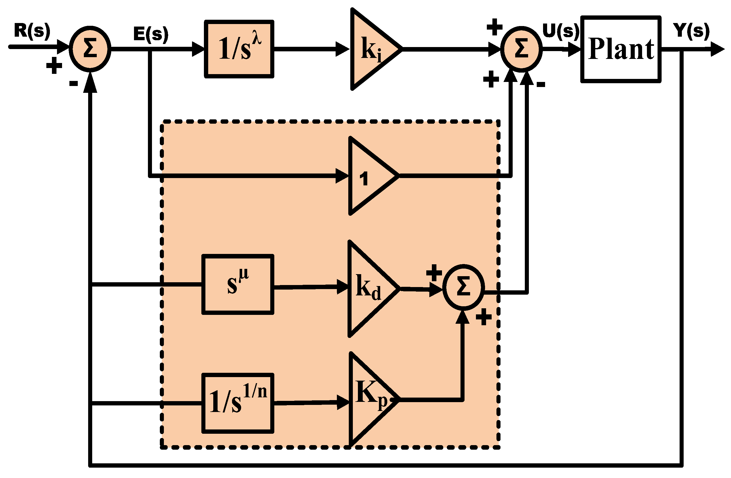
3.1. Robust 1+ Modified Fractional Order PID Controller Formulation

Numerous LFC regulators have been developed and implemented in discussed studies. Recently, fractional order controllers have gained significant attention as alternatives to conventional controllers due to their reduced computation time, higher noise rejection ratio, and lower noise impact [19]. Fractional derivatives and integrals are commonly defined within the Riemann–Liouville (R-L) framework. Using the Laplace transformation, a differential equation with fractional derivatives characterizes a system’s dynamic behavior as a fractional order transfer function. This study employs the Crone approximation proposed by Oustaloup, with the recursive distribution rule defining the frequency range for ’N’ poles and zeros (N = 5), spanning from ωl = 0.001 rad/s to ωh = 1000 rad/s [20].
The configuration of the 1+MFOPID controller, which builds upon the modified FOPID controller principle, is depicted in Figure 2. This configuration comprises the fractional integrator order (λ), integral term (Ki), proportional term (Kp), derivative term (Kd), fractional derivative order (μ), and an additional tuning constant, denoted as “1”. The term “Plant” in the Figure 2 refers to the corresponding power sources incorporated in the test system. In the FOPID controller, feed forwarding is employed for all gains [21]. Conversely, the proposed 1+MFOPID controller utilizes feed forwarding for the integral term and integrator order, while feedback is applied to the remaining parameters [22]. The differential equations delineating the outputs of the FOPID and 1+MFOPID controllers are presented in Equations (7) and (8), respectively.
u ( t ) = e ( t ) K p + e ( t ) D λ K i + e ( t ) D μ K d
u ( t ) = e ( t ) ( 1 + K p ) y ( t ) ( K i + D μ K d )
In this context, y(t) represents the system’s productivity, while u(t) and e(t) denote the control signal and error term, respectively. A step change in the FOPID controller’s set point causes an immediate step change in the output signal U(s), referred to as a “proportional kick” or “derivative kick,” which rapidly alters the actuator control signal. To address these issues, a revised FOPID controller architecture was developed, where the integral gain (Ki) is influenced by the error signal (E). Since the derivative and proportional gains impact the process output (Y(s)), a sudden change in the setpoint input does not affect these terms [23]. Additionally, a constant “1” is included for more efficient tuning. Equation (9) is derived using a plant Gp(s) and the corresponding MFOPID controllers, illustrating the transfer functions of the control circuits.
Y ( s ) R ( s ) = K i G p ( s ) S λ + S λ K p + G p ( s ) K i + K d S λ S μ
Equation (9) illustrates how the proposed modified FOPID controller (MFOPID) improves system response by re-routing the Kp and Kd gains to the feedback loop, thereby eliminating the effects of zeros. Additionally, incorporating a variable (1, in this study) in the controller structure provides an extra tuning parameter that effectively manages transient disturbances. The fundamental objective of incorporating a fractional term in the controller is to enhance control performance by providing greater flexibility in tuning. The fractional orders allow more precise shaping of the controller’s frequency response, improving system robustness, stability, and dynamic response. This added degree of freedom helps in better handling of system uncertainties and achieving smoother control, especially in nonlinear systems. As a result, the 1+MFOPID controller delivers a more favorable system response compared to the MFOPID and FOPID controllers, as vividly demonstrated in the Section 5.

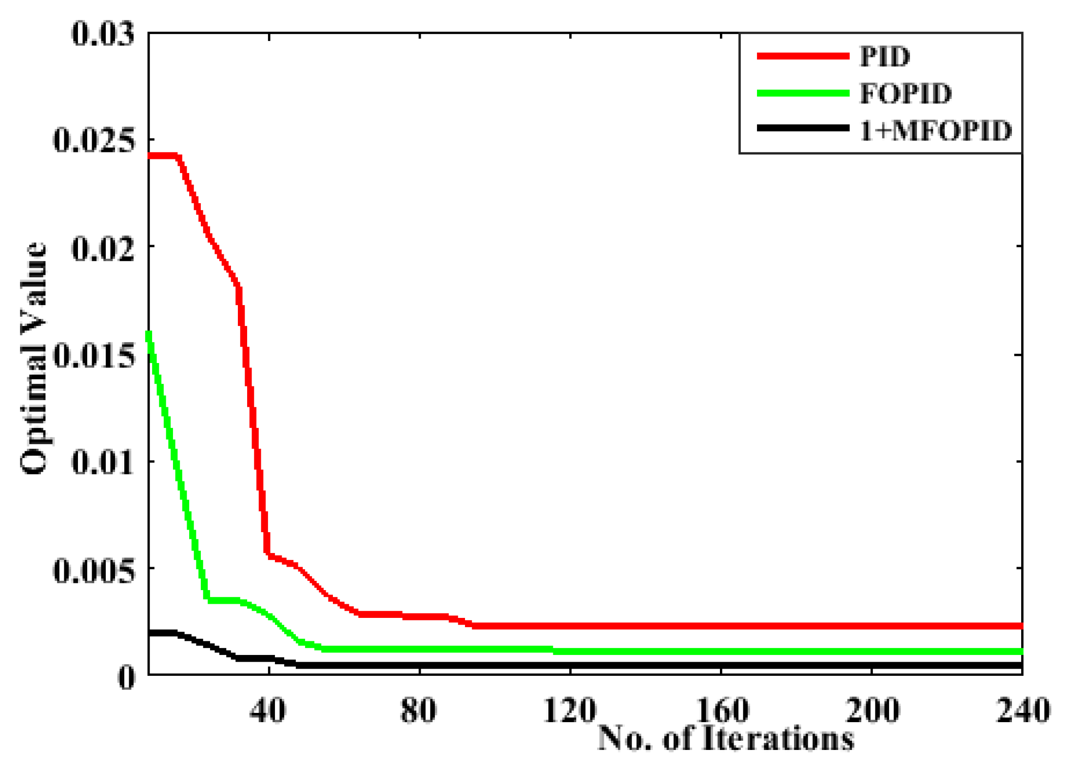
3.2. Development of New Variant of Objective Function

In an effective frequency management scheme, different cost functions are employed to optimize the control strategies and ensure system stability and performance. The choice of cost function in frequency is crucial as it influences the system’s stability, response time, and control effort. IAE and ISE are simpler but may not be ideal for all scenarios. ITAE, ISAE and ITSE, though more complex, offer better long-term performance and stability, making them suitable for more sophisticated control systems [20]. In this context, ISTSE is often considered superior for frequency management schemes because it balances the need for quick error correction with a damping effect that reduces overshoot and oscillations, leading to a more stable and efficient system response. In contrast, ITAE might result in slower responses, and ISAE may lead to oscillations due to its lack of time sensitivity. The expression of ISTSE is formulated as described in Equation (10), where the cost function contains frequency deviation (∆Fi), tie-line power change (∆Ptie ij), t is the time factor, and tsimul. is the simulation time starting from 0 [23].
J = I S T S E = 0 t s i m u l . ( Δ F i + Δ P t i e   i j ) 2 t 2 d t ;     i , j = 1 , 2 , ..... , n   a n d   i j
It is crucial to highlight that the previously discussed measures primarily address the time-domain performance of control systems, often overlooking their frequency-domain characteristics. While these measures improve the system’s dynamic response, they may inadvertently lead to instability [24]. To counteract this tendency and enhance system stability, an improvised cost function based on ISTSE (iISTSE), as defined by Equation(11), is proposed. This function seeks to minimize the ISTSE while maximizing the sum of the damping ratios (DRs) of the system’s poles. As a result, it ensures that unstable poles located in the right half of the s-plane are avoided, since these poles have corresponding damping ratios of −1.
J i m p r o v e d = i m p r o v e d   I S T S E     v e r s i o n = ω 1 Δ J + ω 1 Δ 1 i = 1 N ζ i
Here, N represents the total number of system poles, ζ denotes the damping ratio (DR) of the i-th pole, and ω are weighting parameters that control the relative significance of each term in the new cost function Jimproved. Following extensive iterative optimization trials, the values of ω1 and ω2 (which should not be more than 1),were determined to be 0.2 and 0.8, respectively. These values were found to provide superior performance by effectively balancing both time-domain and frequency-domain characteristics. Hence, the proposed cost function is formulated as follows.
Minimize: Objective Function, Jimproved
Subject to constraints, min. < Kp, Ki, Kd, α,μ < max.
The mentioned cost function plays a central role in optimization techniques, serving as a measure of how well a particular solution satisfies the given constraints and objectives. Optimization algorithms aim to minimize the mentioned cost function by exploring both local and global search spaces. The global search attempts to find a solution in the broadest possible range, ensuring the discovery of the best possible solution, while the local search refines this solution by exploring neighboring values. The result of thisdual approach leads to an optimal value, balancing global exploration and local exploitation, ensuring the best optimal outcome. As discussed, the performance analysis of iISTSE compared withthat of different cost functions considering various controllers is presented in Table 1.

4. Overview of Optimization Technique

Proper tuning of the controller parameter with an optimization technique enhances system stability, minimizes frequency deviations, and ensures a fast, accurate response to disturbances, particularly when integrating diverse energy storage systems with unique dynamic behaviors and nonlinear interactions in a power network [18]. Recently, the βchaotic Harris Hawks optimization (HHO) with opposition-based learning (OBL) is an advanced hybrid optimization technique that enhances the standard HHO algorithm is introduced in solving the complex optimization task [19]. HHO, inspired by the hunting strategies of Harris hawks, has proven effective in solving optimization problems. The HHO belongs to a family of modern metaheuristic algorithms based on the collective hunting behaviors of Harris hawks. Rabbits are the principal food items of Harris hawks andoften flee from the hawks [25]. As a result, two dynamic factors, namely surprise attack by the hawk and the rabbit’s capacity to flee, form the basis for the HHO algorithm. The two steps of the optimizer are exploration and exploitation; there are four substages under exploitation: soft and hard besiege as well as soft and hard besiege with successive fast dives. However, the incorporation of chaotic maps and OBL improves its convergence speed and exploration abilities, making it more robust for complex search spaces [26].
The chaotic maps introduce randomness and diversification in the optimization process. By applying the β distribution to control the chaotic sequence, the algorithm achieves better exploration in the search space. This prevents premature convergence to local optima by allowing a more comprehensive global search. Similarly, another concept that is incorporated into the optimization process is opposition-based learning (OBL) which accelerates the convergence by considering the current population and its opposite solutions simultaneously [27]. This mechanism enhances both the global and local search capabilities by expanding the search space, increasing the probability of finding optimal solutions faster.

5. Result Analysis and Discussion

This study investigates a system that integrates conventional and sustainable power sources, alongside an energy storage system, to maintain load–demand balance and system stability. Efficient control is crucial when multiple sources operate simultaneously, requiring precise tuning of controller settings. To achieve this, an advanced optimizerwas employed for its superior performance. A proposed 1+MFOPID controller was compared with FOPID and conventional PID controllers, as illustrated in Figure 3, to demonstrate its enhanced performance. The controller parameters were constrained within the ranges: Kp, Ki, Kd(0–2.0) and fractional orders (less than 1). Optimized gain parameters are provided in Table 2. Aneigenvector analysis assessedsystem stability, followed by a performance evaluation using various controllers. The study also examined the system’s performance with various storage systems, and sensitivity analysis during the system design process. It provides a concise and precise description of the experimental results, their interpretation, as well as the experimental conclusions.

5.1. Stability Analysis

To evaluate the stability of a power system in frequency control using eigenvalue analysis, the system’s dynamic behavior is first represented by a set of linearized differential equations. These equations depict the relationships between generation, load variations, and frequency regulation. The system is then expressed in state-space form, typically as X = Ax + Bu where x denotes the state vector, A is the system matrix, B represents the control input matrix, and u is the input vector. Stability is assessed by analyzing the eigenvalues of the system matrix A, which reveal the system’s dynamic response over time by following the expression.
Det(A − λI) = 0
The eigenvalues of the system, considering various energy storage configurations, are presented in Table 3. The stability analysis can be interpreted as follows: when all eigenvalues have negative real components, the system is stable, implying that disturbances will naturally decay, and the system will return to equilibrium. Conversely, if any eigenvalue possesses a positive real component, the system becomes unstable, leading to growing deviations that drive the system away from its operating point. Based on the stability interpretation and the data provided in Table 3, the model exhibits negative eigenvalues, with some eigenvalues being negative complex conjugates. This suggests that the system, as a whole, remains within the stable region. However, the presence of the imaginary part in the complex conjugate eigenvalues introduces oscillatory behavior into the system’s response. In such cases, the system will oscillate at a frequency determined by the magnitude of the imaginary component, though these oscillations will eventually dissipate due to the damping effect of the negative real component.

5.2. System Response with the Proposed Controller

The comparative analysis of the three controllers—PID, FOPID, and the proposed 1+MFOPID—based on system performance in a hybrid three-area energy system under a 1% step load perturbation in area-1 highlights critical insights. As shown in Figure 4, the system’s transient response demonstrates that the 1+MFOPID controller, which is optimized using the algorithm, outperforms the conventional PID and FOPID controllers in terms of key performance metrics: overshoot, undershoot, and settling time. These metrics, pivotal in determining system stability and robustness, are further quantitatively validated in Table 4 and Table 5.
The analysis of overshoot and undershoot in Figure 4, as supported by the overshot and settling time in Table 4, reveals that the proposed 1+MFOPID controller results in significantly reduced overshoot and undershoot compared to its counterparts, signifying superior damping characteristics.The 1+MFOPID’s ability to reduce overshoot by approximately 43% compared to PID for ΔF1 and its reduced settling time by 28% highlights its superior dynamic response and stability. This reduced deviation from the set point ensures minimized oscillations following a disturbance in both frequency and tie-line power, contributing to system stability.
Similarly, the 2% settling time, depicted in the above figure and analyzed in Table 5, underscores the controller’s effectiveness. The 1+MFOPID controller achieves the fastest settling time across all tie-lines (10.57 s, 11.61 s, and 21.24 s) and exhibits improved stability with reduced overshoot/undershoot for most cases. The FOPID controller performs better than PID in minimizing overshoot/undershoot but shows slower settling times than 1+MFOPID.The proposed 1+MFOPID controller achieves faster stabilization compared to the traditional PID and FOPID controllers, thereby confirming its superior dynamic performance. The enhanced settling time and reduced transient errors reflect the efficacy of the HHO-tuned 1+MFOPID in achieving optimal control, highlighting its potential for more efficient energy system management. Further, the relationship between frequency fluctuations and tie-line power variations between area 1–2 under the proposed controller is illustrated in Figure 4g. Upon the application of a load, a sudden frequency deviation is observed, leading to a change in tie-line power. Subsequently, the proposed control mechanism is activated, working to stabilize the frequency by supplying additional energy from storage systems and adjacent control areas via the tie-line. As the tie-line power change stabilizes, the frequency deviation also gradually returns to a steady state. This behavior indicates a synergistic relationship between frequency fluctuations and tie-line power dynamics.
Nevertheless, a more meaningful evaluation of the proposed controller could be achieved through the adoption of independent test scenarios, such as simulations using irregular load profiles or the integration of real-world datasets.

5.3. Performance of Different Energy Storage Systems

Each storage technology impacts the system’s dynamic performance differently. UC systems are recognized for their rapid discharge and response capabilities, making them effective in managing short-term frequency deviations and mitigating sudden load changes. However, their energy capacity is limited, restricting their effectiveness in longer-duration events. SMES offers both high power density and quick response time, efficiently absorbing or injecting energy to maintain system frequency during transient conditions. Its superconducting properties ensure minimal energy losses, providing stability by dampening oscillations in frequency and tie-line power.
Battery storage, on the other hand, provides larger energy storage capacity with slower response compared to UC and SMES, making it suitable for both medium- and long-duration frequency regulation. BESS can sustain frequency control for longer durations, reducing tie-line power fluctuations. Battery sharessimilarities with UC, offering fast response times with lower energy capacities, suitable for addressing transient fluctuations but less effective for long-term disturbances as validated from Figure 5. Therefore, a combination of these storage systems, particularly conjunction with battery energy system, can complement each other, balancing quick response with sustained support, thereby enhancing overall system stability and reducing frequency deviations and tie-line power changes in hybrid energy systems. With regards to the speed of response, the battery energy storage system stabilizes the frequency deviation in 12.98 s and 8.12 s in area 1 and 2, respectively. Additionally, it settles the tie-line power deviation between area 2 and 3 in 13.95 s. The SMES and UC storage demonstrate comparable response times. Specifically, SMES stabilizes the frequency deviation in 13.24 s in area 1 and 8.54 s in area 2, while it settles the tie-line power deviation between area 2 and 3 in 14.47 s. Similarly, the UC stabilizes the frequency deviation in 13.67 s and 8.49 s inarea 1 and area 2, respectively, and achieves tie-line power stability between area 2 and 3 in 14.41 s. Thus, it can be inferred that battery has higher speed of response than SMES and UC. This is evident from its comparatively shorter settling times in both frequency deviation and tie-line power stabilization across the respective control areas.
The state of charge (SOC) of a batterystorage system plays a crucial role in its ability to regulate frequency and tie-line power in a three-area frequency controlmodel with thermal, wind, and solar plants.
From the data presented by Table 6, at a 30% SOC, the battery has limited capacity to store or release energy, reducing its effectiveness in mitigating frequency deviations and controlling tie-line power fluctuations. This lower SOC may lead to slower response times, making it challenging to stabilize the system during large disturbances. At 50% SOC, the battery operates more optimally, with a balanced capacity to inject or absorb energy. This level allows moderate control over frequency and tie-line power, effectively addressing medium-sized perturbations and maintaining system stability. At a higher 80% SOC, the battery is well-prepared to provide fast and substantial energy input, allowing for rapid frequency stabilization and tighter control over tie-line power changes. The increased energy reserve enables the BESS to respond to larger disturbances, improving overall system resilience.
Thus, higher SOC levels enhance the battery’s capacity to regulate frequency deviations and maintain steady tie-line power, especially in systems with fluctuating renewable energy sources like wind and solar.

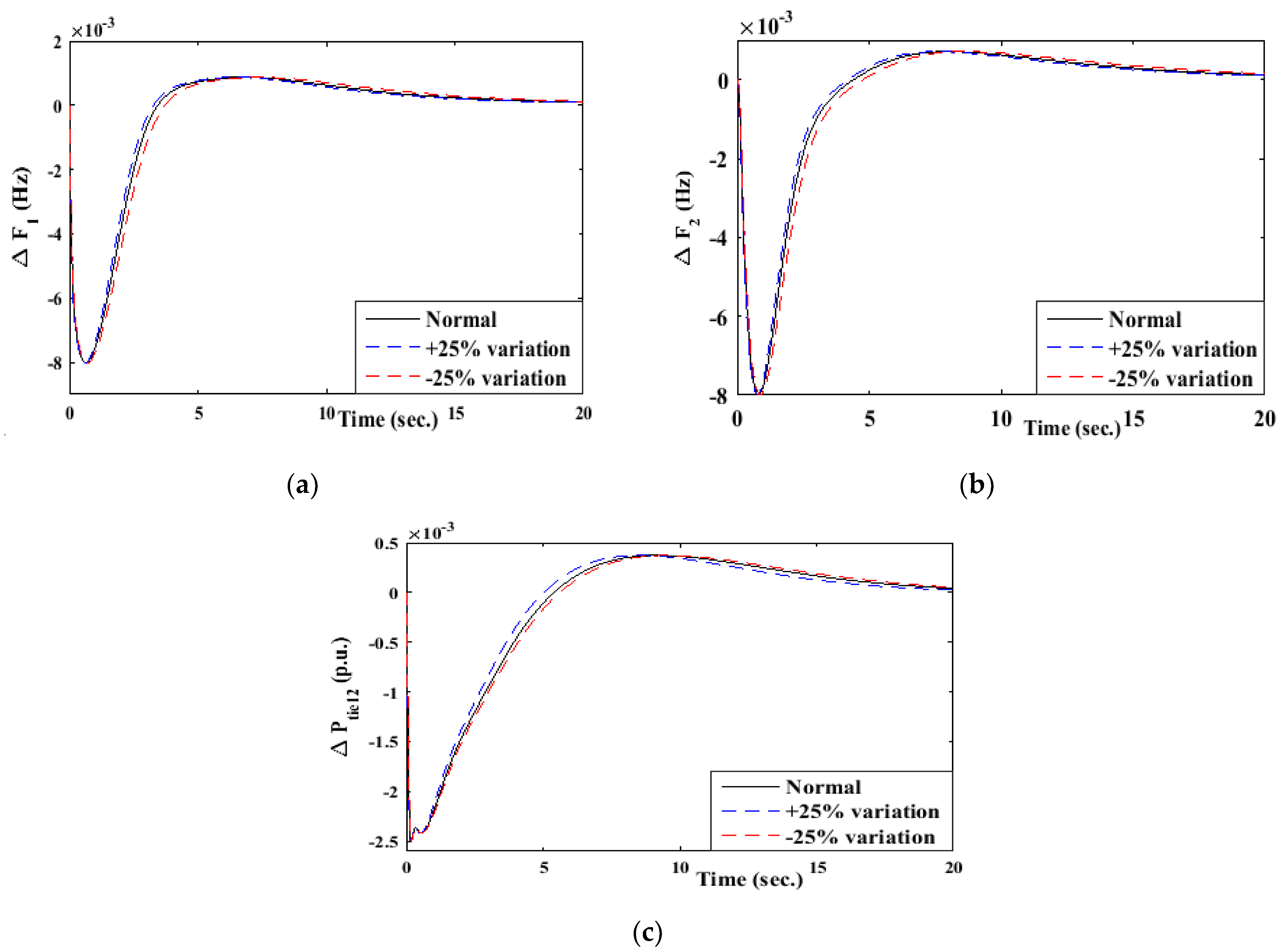
5.4. Sensitivity Analysis of the Internconnected System

In an effective frequency management system, sensitivity analysis is a crucial tool to evaluate how variations in system parameters affect overall performance and stability of the control system. It helps identify which parameters have the most significant impact on frequency regulation and system response to disturbances. Sensitivity analysis typically involves systematically varying key parameters, such as system inertia, governor response, damping coefficients, or controller gains, and observing how these changes influence critical performance metrics like settling time, frequency deviation, and stability margins.
Figure 6 illustrates the effect of percentage changes in system parameters, such as the governor time constant and turbine constant, on system frequency. The analysis shows that when these parameters deviate by more than 25% from their nominal values, the frequency begins to shift from its desired set point. Furthermore, as the percentage change increases, particularly toward higher values, the frequency deviation becomes more pronounced. It is important to note, however, that even at extreme changes in system parameters, although these scenarios may not be practically feasible, the frequency remains within a safe operating range. This stability can be attributed to the effective control mechanisms of the proposed controller. Additionally, the analysis reveals that the system demonstrates relatively low sensitivity to external design parameters, which was a key objective in the development of this sustainable model. Thus, the system maintains robustness and stability across a range of parameter variations, enhancing its reliability under different operational conditions. In the event of a grid fault, the frequency regulation management system experiences a disturbance due to the sudden imbalance between power generation and demand, leading to frequency deviations. To mitigate these effects, the proposed controller, i.e., 1+MFOPID controller, is employed to enhance dynamic performance and robustness. The integration of energy storage devices (batteries, SMES, and UC) further strengthens the system’s ability to respond rapidly. These storages are modelled as first-order transfer functions and provide fast active power support, thereby aiding the 1+MFOPID controller in quickly damping frequency oscillations and restoring nominal conditions.

6. Conclusions and Remarks

Prior hybrid power system systems lacked adaptability and robustness to handle nonlinearities, system uncertainties with the existing controller like the PID and FOPID controller. Thus, this study presents a comprehensive analysis of a hybrid energy system through the implementation of the proposed 1+MFOPID controller, optimized using β chaotic Harris Hawk optimization and an improved ISTSE version of cost function.The system achievedsuperior performance compared to conventional and existing controllers. The results highlight the proposed controller’s ability to significantly reduce overshoot, undershoot, and oscillations, leading to improved damping characteristics and enhanced system stability. Eigenvector analysis confirms the system’s robustness, while sensitivity analysis indicates low susceptibility to uncertainty in external design parameters. Furthermore, the combination of storage systems demonstrates a synergistic effect, with UC and SMES providing rapid transient response and battery systems offering sustained support. Moreover, the combination of battery with other storage devices effectively reduces transient shoots, minimizes steady-state times, and enhances the overall resilience of the hybrid system. Therefore, the integrative approach validates the efficacy of the 1+MFOPID controller with improved ISTSE objective function ensuring stable, efficient, and sustainable energy system operation, offering significant advancements in robust frequency regulation strategies.Future research can explore the scalability of the proposed approach in larger power networks, incorporating independent test scenarios such as real-world datasets or irregular load profiles. Additionally, addressing operational challenges like cyber-attacks and the computational complexity of real-time implementation will further enhance the practical applicability of the controller.

Author Contributions

Conceptualization, S.S.P.; methodology, S.S.P. and U.S. software, S.S.P.; validation, S.S.P., U.S. and S.M.; formal analysis; investigation, S.S.P. and U.S.; resources, S.S.P.; data curation, S.S.P. and U.S.; writing—original draft preparation, S.S.P.; writing—review and editing, S.S.P., U.S. and S.M.; visualization, S.S.P.; supervision, U.S. and S.M.; project administration, U.S. and S.M.; funding acquisition, U.S. and S.M. All authors have read and agreed to the published version of the manuscript.

Funding

This research received no external funding.

Data Availability Statement

Data are contained within the article.

Acknowledgments

The authors acknowledge the computing facility of IIIT Bhubaneswar and CAPGS-BPUT, Rourkela for carryout the research work.

Conflicts of Interest

The authors declare no conflicts of interest.

Abbreviations

RESRenewable Energy Sources
USUltracapacitor
SMESSuper Magnetic Energy Storage
PVPhoto Voltaic
WTGWind Turbine Generator
LFCLoad Frequency Control
FRMSFrequency Regulation Management System
FOPIDFractional Order Proportional Integral Derivative
SLPStep Load Perturbation

Appendix A

  • Thermal power plant
Rating of machine = 500 MW; Equivalent droop constant, Reqv = 2.4 Hz/MW; Synchronizing time constant, 2πT12 = 0.545 p.u.; Bias factor, Bi = 0.433; Time constants, Tgs = 0.008 s; Tts = 1.08 s; TP1 = 20.00 s; Tt1 = 1.02 s;gain constants, Kr1 = 0.04 s; KP1 = 120.
  • Hydro power plant
Time constants, Tw = 48.7 s; Gain constants, Kp = 0:513 s; Kd = 10 s; Ki = 1 s.
  • Solar PV power plant
K = 4.64.
  • Wind turbine generator
Gain constants, Ka = 1.25; Kg = 1.40; Kc = 0.80; Time constants, Ta = 0.60 s; Tg = 0.041 s; Tc = 0.038 s.
  • UC
Gain constants, KUC = −0.7, Time constants, Tuc = 0.9 s.
  • SMES
Gain constants, KSMES = 0.12, Time constants, Tuc = 0.03 s.
  • Battery
Gain constants, Kbattery = 0.37, Time constants, TBattery = 0.459 s.

References

  1. Kundur, P. Power System Stability and Control; McGraw-Hill: New York, NY, USA, 1994. [Google Scholar]
  2. Tasnin, W.; Saikia, L.C. Comparative Performance of Different Energy Storage Devices in AGC of Multi-Source System Including Geothermal Power Plant. J. Renew. Sustain. Energy 2018, 10, 024101. [Google Scholar] [CrossRef]
  3. Pham, T.N.; Trinh, H.; Oo, A.M.T. Distributed Control of HVDC Links for Primary Frequency Control of Time-Delay Power Systems. IEEE Trans. Power Syst. 2019, 34, 1301–1314. [Google Scholar] [CrossRef]
  4. Franklin, R.V.R.; Abdul Kareem, P.F. Frequency Regulation in Conventional, Deregulated and Microgrid Systems: A Review on Designs, Strategies, Techniques and Related Aspects. IETE J. Res. 2023, 69, 7476–7494. [Google Scholar] [CrossRef]
  5. Arya, Y. AGC of Restructured Multi-Area Multi-Source Hydrothermal Power Systems Incorporating Energy Storage Units via Optimal Fractional-Order Fuzzy PID Controller. Neural Comput. Appl. 2019, 31, 851–872. [Google Scholar] [CrossRef]
  6. Hosseini, S.A.; Toulabi, M.; Ashouri-Zadeh, A.; Ranjbar, A.M. Battery energy storage systems and demand response applied to power system frequency control. Int. J. Electr. Power Energy Syst. 2022, 136, 107680. [Google Scholar] [CrossRef]
  7. Amir, M.; Zaery, M.; Singh, K.; Hussain, S.S.; Abido, M.A. Enhancement of Frequency Regulation by TFOID Controller in Hybrid Renewable Energy with Battery Storage System Based Multi Area Microgrids. IEEE Access 2024, 12, 110813–110828. [Google Scholar] [CrossRef]
  8. Moghaddam, H.A.; Saeedinia, M.H.; Mohamadian, S.; Mahdavi, M.S.; Gharehpetian, G.B. Integrated modeling of power network and connected flywheel energy storage system for optimal power and energy ratings of flywheel. IEEE Trans. Energy Convers. 2020, 36, 1589–1599. [Google Scholar] [CrossRef]
  9. Alghamdi, S.; Alqarni, M.; Hammad, M.R.; AboRas, K.M. First-of-its-kind frequency enhancement methodology based on an optimized combination of FLC and TFOIDFF controllers evaluated on EVs, SMES, and UPFC-integrated smart grid. Fractal Fract. 2023, 7, 807. [Google Scholar] [CrossRef]
  10. Meseret, G.M.; Saikia, L.C. Design of intelligent-based cascaded controller for AGC in three-area diverse sources power systems-incorporated renewable energy sources with SMES and parallel AC/HVDC tie-lines. Electr. Eng. 2024, 106, 793–814. [Google Scholar] [CrossRef]
  11. Murali, S.; Shankar, R.; Sharma, P.; Singh, S. Assessment of power system resiliency with new intelligent controller and energy storage systems. Electr. Power Compon. Syst. 2024, 52, 1414–1436. [Google Scholar] [CrossRef]
  12. Mohamed, A.; Wazeer, E.M.; El Masry, S.M.; Ghany, A.A.; Mosa, M.A. A novel scheme of load frequency control for a multi-microgrids power system utilizing electric vehicles and supercapacitors. J. Energy Storage 2024, 89, 111799. [Google Scholar] [CrossRef]
  13. Saini, N.; Ohri, J. Optimal and Robust Load Frequency Control for Hybrid Power System Integrated with Energy Storage Device by Sine Cosine Algorithm. Wirel. Pers. Commun. 2024, 138, 1955–1983. [Google Scholar] [CrossRef]
  14. Huang, C.; Yang, M.; Ge, H.; Deng, S.; Chen, C. DMPC-based load frequency control of multi-area power systems with heterogeneous energy storage system considering SOC consensus. Electr. Power Syst. Res. 2024, 228, 110064. [Google Scholar] [CrossRef]
  15. Khan, I.A.; Mokhlis, H.; Mansor, N.N.; Illias, H.A.; Awalin, L.J.; Wang, L. New trends and future directions in load frequency control and flexible power system: A comprehensive review. Alex. Eng. J. 2023, 71, 263–308. [Google Scholar] [CrossRef]
  16. Khokhar, B.; Parmar, K.S. Utilizing diverse mix of energy storage for LFC performance enhancement of a microgrid: A novel MPC approach. Appl. Energy 2023, 333, 120639. [Google Scholar] [CrossRef]
  17. Gulzar, M.M.; Iqbal, M.; Shahzad, S.; Muqeet, H.A.; Shahzad, M.; Hussain, M.M. Load frequency control (LFC) strategies in renewable energy-based hybrid power systems: A review. Energies 2022, 15, 3488. [Google Scholar] [CrossRef]
  18. Gupta, D.K.; Jha, A.V.; Appasani, B.; Srinivasulu, A.; Bizon, N.; Thounthong, P. Load frequency control using hybrid intelligent optimization technique for multi-source power systems. Energies 2021, 14, 1581. [Google Scholar] [CrossRef]
  19. Pati, S.S.; Subudhi, U. Stability Analysis of a Multi-area Renewable System and Frequency Control with Improved Chaotic Harris Hawk Optimization Algorithm. Arab. J. Sci. Eng. 2024, 49, 6531–6550. [Google Scholar] [CrossRef]
  20. Mohamed, M.A.E.; Jagatheesan, K.; Anand, B. Modern PID/FOPID controllers for frequency regulation of interconnected power system by considering different cost functions. Sci. Rep. 2023, 13, 14084. [Google Scholar] [CrossRef]
  21. Tepljakov, A.; Alagoz, B.B.; Yeroglu, C.; Gonzalez, E.A.; Hosseinnia, S.H.; Petlenkov, E.; Ates, A.; Cech, M. Towards industrialization of FOPID controllers: A survey on milestones of fractional-order control and pathways for future developments. IEEE Access 2021, 9, 21016–21042. [Google Scholar] [CrossRef]
  22. Wadi, M.; Shobole, A.; Elmasry, W.; Kucuk, I. Load frequency control in smart grids: A review of recent developments. Renew. Sustain. Energy Rev. 2024, 189, 114013. [Google Scholar] [CrossRef]
  23. Daraz, A.; Malik, S.A.; Basit, A.; Aslam, S.; Zhang, G. Modified FOPID controller for frequency regulation of a hybrid interconnected system of conventional and renewable energy sources. Fractal Fract. 2023, 7, 89. [Google Scholar] [CrossRef]
  24. Çelik, E.; Öztürk, N.; Houssein, E.H. Improved load frequency control of interconnected power systems using energy storage devices and a new cost function. Neural Comput. Appl. 2023, 35, 681–697. [Google Scholar] [CrossRef]
  25. Shehab, M.; Mashal, I.; Momani, Z.; Shambour, M.K.Y.; AL-Badareen, A.; Al-Dabet, S.; Bataina, N.; Alsoud, A.R.; Abualigah, L. Harris hawks optimization algorithm: Variants and applications. Arch. Comput. Methods Eng. 2022, 29, 5579–5603. [Google Scholar] [CrossRef]
  26. Jia, D.; Wang, D. A Maximum Power Point Tracking (MPPT) Strategy Based on Harris Hawk Optimization (HHO) Algorithm. Actuators 2024, 13, 431. [Google Scholar] [CrossRef]
  27. Fakhfour, K.; Pourfayaz, F. Size Optimization of Standalone Wind-Photovoltaic-Diesel-Battery Systems by Harris Hawks Optimization (HHO): Case Study of a Wharf Located in Bushehr, Iran. Int. J. Electr. Power Energy Syst. 2024, 163, 110353. [Google Scholar] [CrossRef]
Figure 1. Block diagram representation of three areas of an interconnected power system with energy storage.
Electricity 06 00022 g001
Figure 2. Proposed 1+MFOPID controller structure.
Electricity 06 00022 g002
Figure 3. Comparative assessment of different controllers applied with the iISTSE cost function.
Electricity 06 00022 g003
Figure 4. Comparative assessment of (ac) frequency deviation of areas 1, 2, and 3, respectively, and (df) tie-line power of area 1–2, 1–3, and 2–3, respectively, for different controllers for three areas of the model (g) frequency deviation in area 1 with change of tie-line power in area 1–2.
Electricity 06 00022 g004
Figure 5. Comparative assessment of impact of energy storage (a,b) on frequency deviation in area 1 and 2, respectively, and (c) on tie-line power in area 2–3 for a three-area model.
Electricity 06 00022 g005
Figure 6. Comparative assessment of parameter uncertainty on (a,b) frequency deviation in area 1 and 2, respectively, and (c) tie-line power on area 1–2 for three-area of the model.
Electricity 06 00022 g006
Table 1. Performance analysis of different cost functions considering various controllers.
ControllerOptimal Value Considering the Cost Function
ISE ITAEISTEISTSEiISTSE
PID0.05740.00920.07520.00440.0041
FOPID0.05050.00850.06750.00370.0035
1+MFOPID0.04550.00740.05570.00230.0017
Table 2. Optimized gain parameters of the proposed 1+MFOPID controller.
AreaControllerOptimal Controller Parameters
KpKiKdαμ
1PID2.94122.08102.1012--
FOPID2.28701.95532.35100.550.67
1+MFOPID2.28722.01522.11230.490.68
2PID2.65822.88102.1112--
FOPID2.15801.91532.55100.750.72
1+MFOPID2.28512.11522.10250.790.78
3PID2.26512.65272.5621--
FOPID2.31332.07512.25520.640.68
1+MFOPID2.65822.65102.13570.820.72
Table 3. Stability analysis using Eigenvalues considering various controllers.
ConditionsEigen ValuesDamping Ratio (min.)
Proposed Controller−16.0630, −4.7140 ± j5.2284, −14.400 ± j9.4010,−13.1660, −11.4040 ± j8.2014, −11.2010 ± j0.5400, −5.8010 ± j4.2987, −4.2580 ± j8.012−2.5200, −3.6103 ± j1.2284, −2.1205 ± j1.6533, −1.7403 ± j1.5280, −1.3000 ± j4.1170, −1.7510 ± j11.1004, −1.3442 ± j7.0513, −1.2100 ± j9.5587, −1.1705 ± j6.8473, −1.1033 ± j1.0563, −1.13200 ± j3.11700.392
FOPID
Controller
−1.1710 ± j1.1020, −3.0103 ± j3.2474, −10.7100 ± j10.820, −2.0255 ± j1.9863, −4.7113 ± j14.2563, −10.10030,
−9.5440 ± j1.2016, −2.0400 ± j3.2578, −2.8510 ± j1.1624, −1.3002 ± j8.9223, −6.1211 ± j11.6587, −1.2110 ± j9.1110, −7.0505 ± j6.4713, −4.8113 ± j1.8243, −5.0550,
−4.1140 ± j5.8584, −2.3700 ± j13.0170, −5.1400 ± j1.2777
0.285
PID Controller−0.0000 ± j0.0011, −0.0003 ± j0.3000,
−3.3310 ± j0.8010, −2.8141 ± j1.7800, −1.8111 ± j0.7150, −1.9203 ± j5.6013, −0.8870 ± j8.2118, −1.1542 ± j0.4044,
−0.1455 ± j0.1021, −0.4720 ± j2.1010, −0.9110 ± j0.2230, −1.3897 ± j1.8821, −0.1656 ± j2.0050, −0.4200 ± j0.0584
0.174
Without Controller−0.1005 + j0.0050, −3.7203 + j0.2400, 1.5700 + j0.8275,
0.8500, 1.1901 ± j0.4270, 0.1200, 0.1009 + j0.0000,
−0.0703 ± j0.0713, 0.0880 ± j0.0479,−0.1570 ± j0.0554, 0.0995, −0.1520 ± j0.3001, −0.7180 ± j0.1230, −0.1056 ± j0.2550, −0.3400 ± j0.0284, 0.916 ± j0.0780, −0.9300 ± j0.1584
0.122
Table 4. Mathematical parameters for frequency fluctuation.
Controller∆F1∆F2∆F3
Over/Under Shoot (10−3)Settling Time
(2%)
Over/Under Shoot (10−3)Settling Time (2%)Over/Under Shoot (10−3)Settling Time (2%)
PID13.8417.1514.9416.3724.7417.85
FOPID11.2514.4512.1712.8418.5417.24
1+MFOPID7.9512.257.907.9813.1015.22
Table 5. Mathematical parameters for tie-line power change.
Controller∆Ptie12∆Ptie23∆Ptie13
Over/Under Shoot (10−3)Settling Time
(2%)
Over/Under Shoot (10−3)Settling Time (2%)Over/Under Shoot (10−3)Settling Time (2%)
PID3.5818.2127.5514.854.1717.97
FOPID1.7517.7526.4114.053.1921.90
1+MFOPID5.7210.5715.5411.613.0421.24
Table 6. Mathematical parameters for different SOC levels.
IndicesParameterSOC Level
30%50%80%
Over/under shoot (10−3)∆F19.987.955.88
∆F211.569.907.98
∆F315.6513.1011.59
∆Ptie127.855.724.50
∆Ptie2316.6515.5413.65
∆Ptie133.953.042.85
Settling time (10−3)∆F113.5512.259.85
∆F29.877.985.84
∆F318.5515.2211.25
∆Ptie1213.4010.578.86
∆Ptie2313.8411.619.54
∆Ptie1325.6721.2419.27
Disclaimer/Publisher’s Note: The statements, opinions and data contained in all publications are solely those of the individual author(s) and contributor(s) and not of MDPI and/or the editor(s). MDPI and/or the editor(s) disclaim responsibility for any injury to people or property resulting from any ideas, methods, instructions or products referred to in the content.

