1. Introduction
Geological face mapping is perhaps the most important process of representing the stratigraphic, geological, and tectonic structures found at an open pit mine. The ultimate target is to optimize the exploitation planning and increase the efficiency and productivity of the mine, which in turn results in a reduction in the exploitation cost. In this article, a new perspective is studied, concerning geological face mapping, through an innovative technology, such as UAV (Unmanned Aerial Vehicle) photogrammetry. Preliminary work was undertaken in 2018 as a first attempt at this approach [
1]. The technological evolution in this field comes with remote sensing techniques, for example, ground-based, close-range hyperspectral sensors measure remote reflectance properties of mineral and rock masses, resulting in unsupervised classification waste from ore [
2]. Many other researchers have recently published articles, which present numerous cases of UAV-photogrammetry applications, such as the identification of faults, fractures, bedding surfaces [
3], rock mass discontinuities and kinematic stability of pit slopes [
4], the data collection for geological survey and generation of thematic maps with potential landslides and steep rock faces [
5,
6], the classification of the lithology of mining face, and using photogrammetry point cloud data and machine learning algorithms [
7]. The drone-photogrammetry technique has contributed to geological mapping and monitoring for many years, also providing feedback on slope stability, mineral exploration, blasting processes, and model improvements [
8,
9,
10,
11,
12].
In this paper, a lignite front of the South Field Mine, located at the Lignite Center of Western Macedonia in Greece, was studied. This mine will be the last in operation in the coming years in the context of energy transition and decarbonization strategies. Therefore, the selective extraction of various qualitative lignite seams becomes more imperative and necessary as the share of lignite in the country’s energy mix decreases and, consequently, its cost increases.
The Mining Planning Department of the South Field Mine has successfully used the method of photogrammetry for geological face mapping. The lignite layers are of the “zebra” type. The co-extraction of sterile materials is inevitable, as there is a sequence of sedimentary layers such as marls, clays, and sands along with lignites. The thickness of the layers ranges from 10 to 20 cm and reaches up to 5–10 m, with an average thickness of lignite layers of 2 m. Traditional face mapping from geologists is no longer preferred because it is laborious, time-consuming, and inaccurate, especially when it deals with the thickness of the sediments. Through the UAV-photogrammetry technique, both the spatial development of minable lignite seams and the exact position of the face sampling point areas able to be determined. The labor staff of the mine approaches the bench faces, which have a height of about 20 m, only for sampling. The lignite quality is determined by analyzing these samples in the laboratory (proximate analysis of moisture, volatile matter, ash, carbon, and calorific values). To sum up, the combination of UAV photogrammetry and face sampling provides all the information about the spatial and qualitative characteristics of the minable lignite seams, which is essentially important for the exploitation of the mine and particularly valuable for the operators of the bucket-wheel excavators.
2. Materials and Methods
The quality of lignite seams, their geometric characteristics, the vertical extent of each minable package consisting of numerous lignite seams separated by intercalated sterile seams, the tectonic features of the deposit, such as faults or folds, and the produced lignite stockpiling options (either in the mine bunker or in the power plant stockyard) are all parameters that are processed in the mine planning study. In this framework, face mapping adds valuable data, including dangerous water flow patterns and preliminary indications of possible landslides. The results from face mapping are delivered in an appropriate form to engineers, supervisors, and operators of excavators and belt conveyors so that everyone can receive the acknowledged minable lignite seams. Hereby, the face mapping of a bench of lignite is presented. The lignite bench S3 is the third bench of Sector 6 of the South Field Mine.
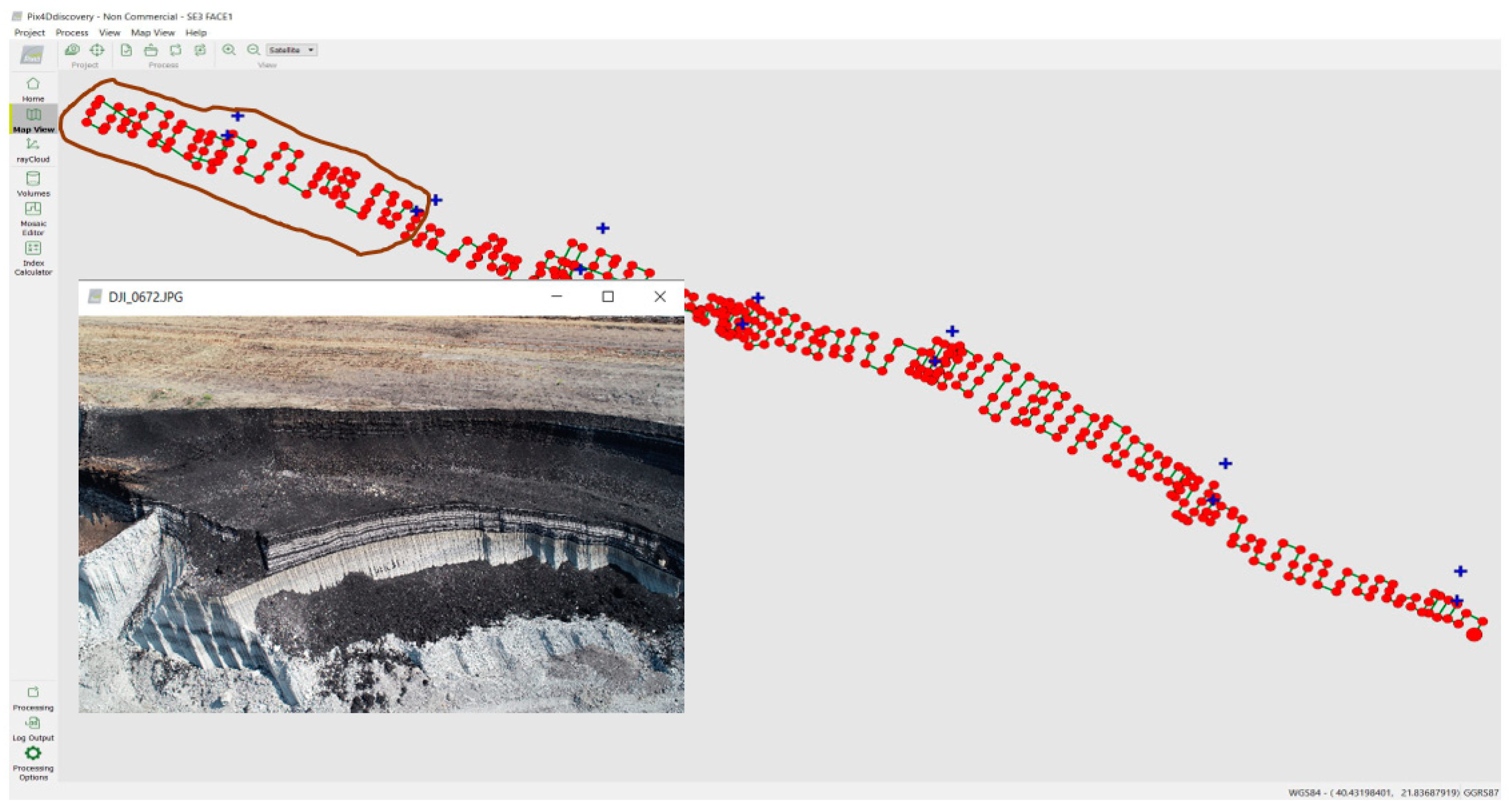
The whole process of face mapping takes place as follows: A flight was carried out with a small helicopter of type Phantom4Pro, which is suitable for the procedure because it is small, flexible, easy to use, able to fly at low altitudes, and with high-resolution camera for photos. The resolution of the photos is of high accuracy of a few centimeters but varies each time depending on the height and photo overlap. Although it is not easy for the drone to fly upwards or downwards along the fronts, this is necessary for collecting the spatial data required. Flights shall be carried out at a suitable lateral angle and not vertically. One drawback worth mentioning is that the shooting angle prohibits photos from showing the horizon. The drone operator must be careful while taking the photos, because if the sky is visible, the point cloud that is created afterward is not reliable. The flight takes place from an altitude of less than 40 m, and the face of bench S3, which is about two kilometers long, is photographed by many overlapping photos (usually over 200, depending on the extent of the study area). The equipment also includes square tiles of Plexiglas sized 0.5 m × 0.5 m, which are colored with a special coating of black or white to be distinguishable. These tiles are photographed, and their exact position is also measured with a GPS. They are the so-called Ground Control Points (GCP), necessary for the georeferencing that will be performed with Pix4Discovery software of Version 4.5.6. The GCPs are placed on the floor of the S3 bench, as close as possible to the mining face (
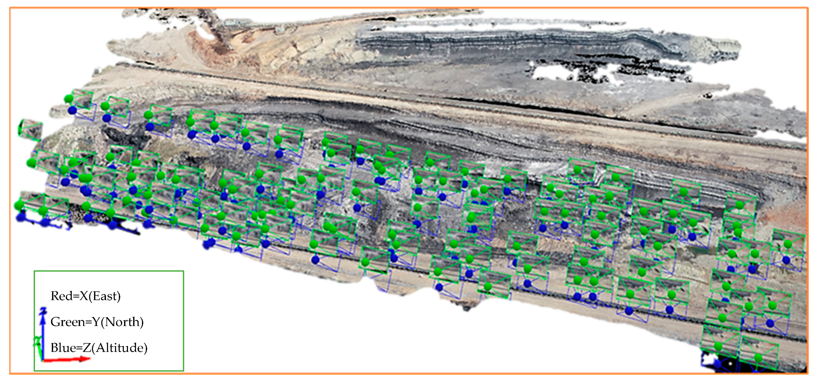
Figure 1). The composition of all images using Pix4Discovery software results in the creation of the model of the entire face of S3 in a few minutes (
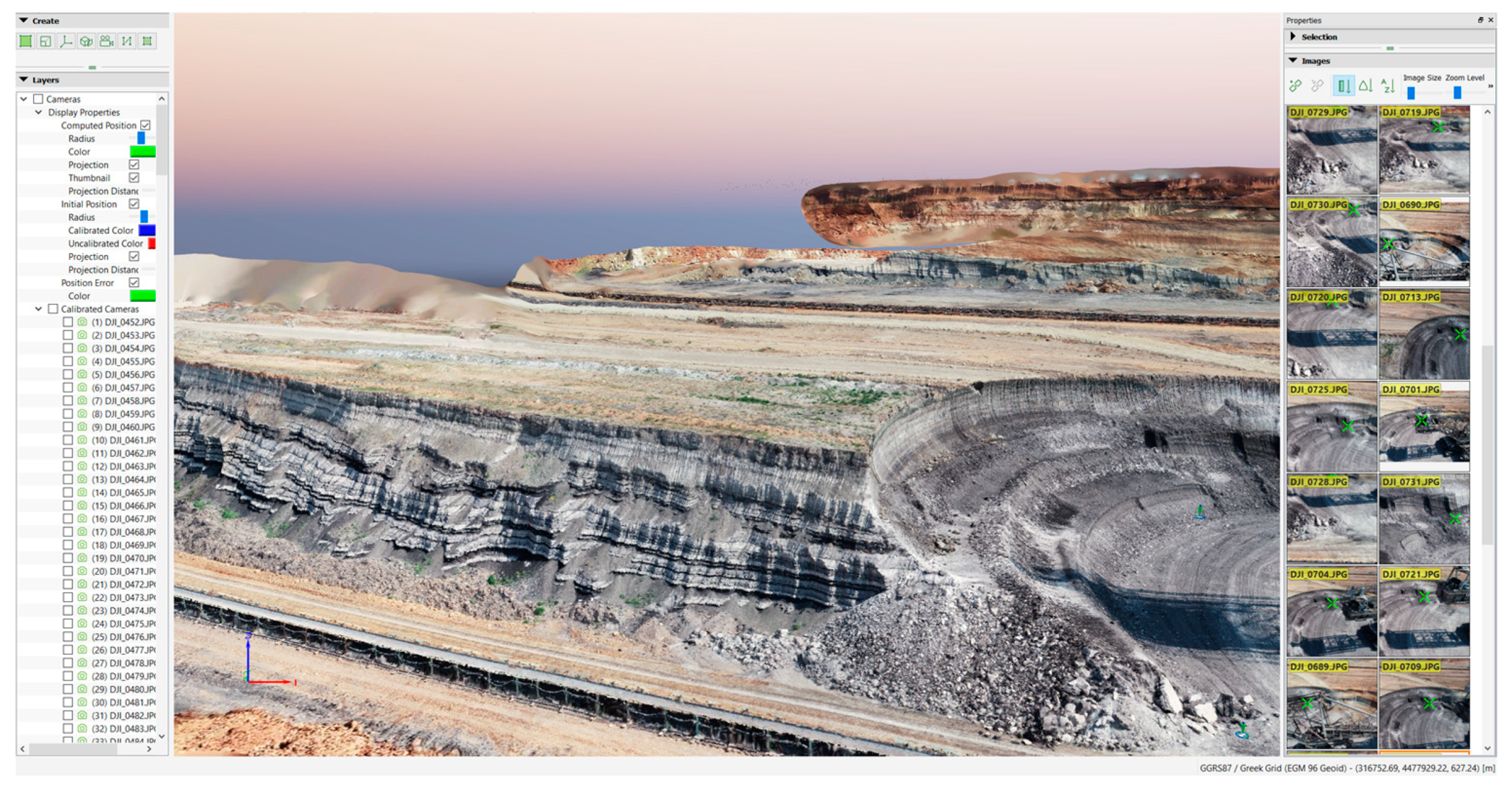
Figure 2). Eventually, the final product is a cloud of points, and with the final composition of the photographs, the three-dimensional and georeferenced model of the surface of the entire S3 bench is obtained (
Figure 3). Finally,
Figure 3 shows a view from the Pix4D program, with the photos on the right side.
3. Results and Discussion
What we ultimately obtain as a result is the three-dimensional depiction of the bench S3 face along its entire length. This depiction is georeferenced, each point has x, y, and z coordinates, so its location is known. Moreover, any object designed on the face, with the help of the Pix4D program, can be imported into another AutoCAD drawing program, or any other mining software such as Vulcan, Carlson, Surfer, etc., for any further processing.
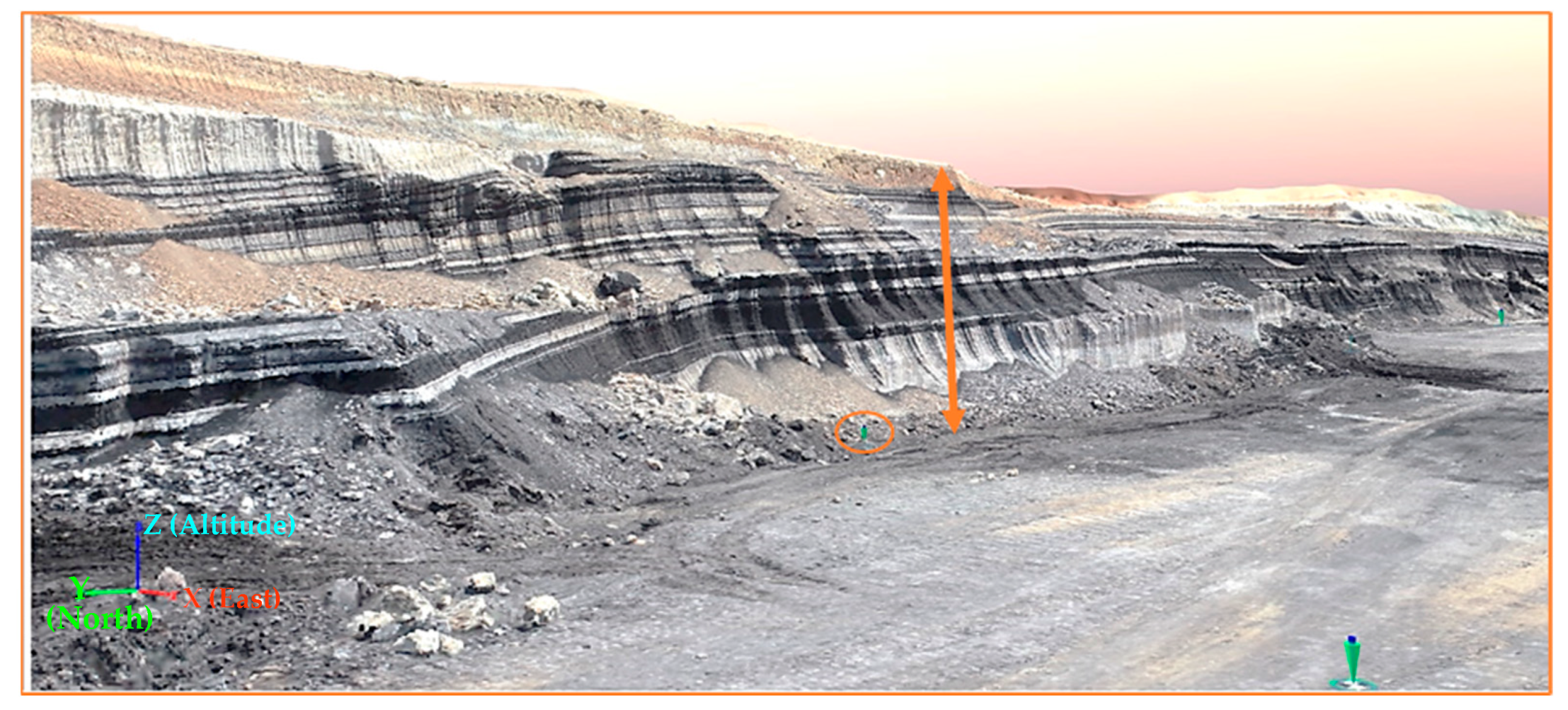
For instance, in
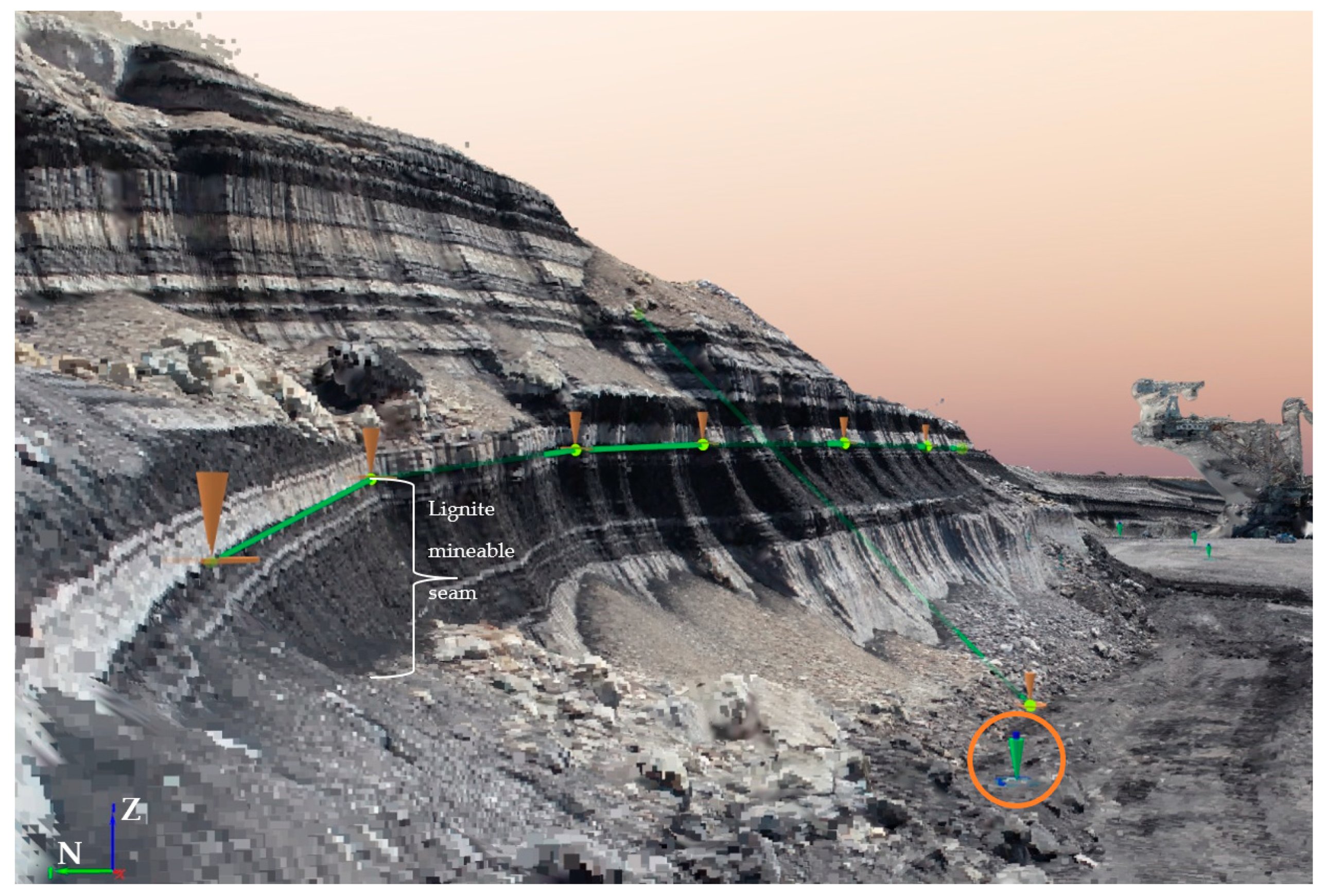
Figure 4 is shown another view from the Pix4D software, which is zoomed in. A part of the bench S3 face seems are presented and a lot of measurements can take place, such as the face height, the thickness of the lignite seams and the minable packages of lignite and intercalated sterile seams, the altitudes, etc. Moreover,
Figure 5 shows the same area as in
Figure 4 but from another angle, as there is the possibility of a 3D orbit in the Pix4D software. The green line presents the roof of a seam, and it is georeferenced; that is, it can be imported to any design program such as AutoCAD, Vulcan, etc.
Where lignite is present, sampling can be carried out on-site. The samples come from minable seams, consisting of several layers that are co-mined together, and they are of maximum thickness usually up to 4–6 m.
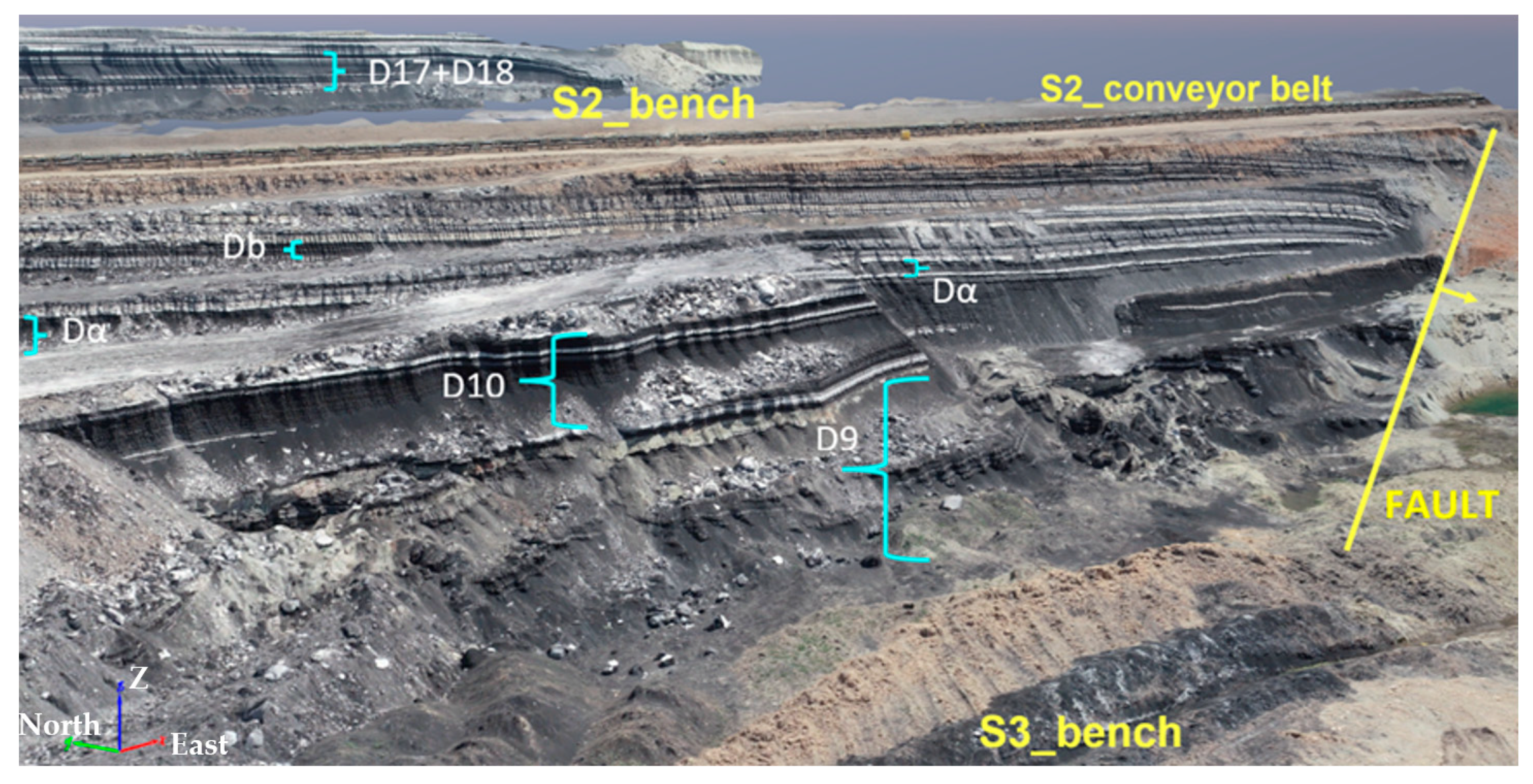
Figure 6 shows the locations from where lignite sampling was realized. The samples D17 and D18 (
Figure 7) derive from the S2 bench. The samples D9, D10, Da, and Db derive from bench S3. All the samples were analyzed at the Analysis and Control Laboratory Subsector of PPC, located in the Standard Chemical Laboratory of Northern Greece, in Kozani. The results shown in
Table 1 define the lignite quality of part of bench S3, by means of proximate analysis of total Moisture, Ash dry-free, Lower Calorific Value, Sulfur dry-free, Carbon dioxide dry-free, and free Calcium oxide. All these values determine the selective extraction and disposal of extractable lignite. Furthermore, all these data can be imported into a database of drilling, survey, or assay data, having the capability to improve the geological and mainly the reserve model.
4. Conclusions
The effectiveness of this application (UAV photogrammetry for face mapping) lies mainly in fieldwork, because it becomes a valuable tool for a geologist whose task is to map a large volume of rocks in a short time in surface mines. The final conclusions for discussion can be the following advantages: (i) The time of the whole procedure of face mapping is drastically reduced, it takes maybe 2 to 3 h per face. (ii) There is a strong possibility of correction of drilling data and recalculation of mining models. The exact position of each minable seam is known. (iii) Whenever the front bench changes its features, then easily, almost costless, and with safety, this face mapping technique can be repeated as many times as it is necessary. (iv) All the appropriate information from face mapping is given to operators of bucket wheel excavators. It is a great help for them to obtain the selective minable seams. (v) With frequent mapping, the change of face slopes in terms of their stability and any dangerous areas locally for landslides is monitored. A disadvantage could be the quality and resolution of the photos. There is also a restriction concerning the appropriate flight as the sky should not be photographed for reliability reasons. Advanced technology equipment could help these shortcomings to be solved.
Author Contributions
Conceptualization, A.P. and K.P.; methodology, A.P. and K.P.; validation, F.P. and I.K.; formal analysis, A.P., I.K. and F.P.; investigation, A.P. and K.P.; resources, A.P. and K.P.; data curation, F.P. and I.K; writing—original draft preparation, A.P.; writing—review and editing, F.P. and I.K.; visualization, I.K.; project administration, A.P., F.P. and I.K. All authors have read and agreed to the published version of the manuscript.
Funding
This research received no external funding.
Institutional Review Board Statement
Not applicable.
Informed Consent Statement
Not applicable.
Data Availability Statement
The data presented in this study are available on request from the corresponding author.
Conflicts of Interest
The authors declare no conflict of interest.
References
- Karnaris, I.; Kolovos, N. Open Pit Mine 3D Geological face mapping perspectives obtained by a fully automated, terrain following, rotary-wing UAVs mission. In Proceedings of the 14th International Symposium of Continuous Surface Mining, Thessaloniki, Greece, 23–26 September 2018. [Google Scholar]
- Windrim, L.; Melkumyan, A.; Murphy, R.J.; Chlingaryan, A.; Leung, R. Unsupervised ore/waste classification on open-cut mine faces using close-range hyperspectral data. Geosci. Front. 2023, 14, 101562. [Google Scholar] [CrossRef]
- Vasuki, Y.; Holden, E.-J.; Kovesi, P.; Micklethwaite, S. A Geological Structure Mapping Tool using Photogrammetric Data. In Proceedings of the 23rd International Geophysical Conference and Exhibition, Melbourne, Australia, 11–14 August 2013. [Google Scholar]
- Medinac, F.; Esmaeili, K. Integrating unmanned aerial vehicle photogrammetry in design compliance audits and structural modeling of pit walls. In Slope Stability 2020; Dight, P., Ed.; Australian Centre for Geomechanics: Perth, Australia, 2020; pp. 1439–1454. ISBN 978-0-9876389-7-7. [Google Scholar]
- Kahar, M.A.A.; Hussin, H.; Madun, A.; Talib, M.K.A.; Wahab, S.W. Geological Terrain Mapping using Geographic Information System (GIS) and Drone Photogrammetry. J. Sustain. Undergr. Explor. 2021, 1, 1–9. [Google Scholar]
- Hao, J.; Zhang, X.; Wang, C.; Wang, H.; Wang, H. Application of UAV Digital Photogrammetry in Geological Investigation and Stability Evaluation of High-Steep Mine Rock Slope. Drones 2023, 7, 198. [Google Scholar] [CrossRef]
- Beretta, F.; Rodrigues, A.L.; Peroni, R.d.L.; Costa, J.F.C.L. Using UAV for automatic lithological classification of open pit mining front. REM Int. Eng. J. 2019, 72 (Suppl. S1), 17–23. [Google Scholar] [CrossRef]
- Honarmand, M.; Shahriari, H. Geological Mapping Using Drone-Based Photogrammetry: An Application for Exploration of Vein-Type Cu Mineralization. Minerals 2021, 11, 585. [Google Scholar] [CrossRef]
- Tsachouridis, S.; Pavloudakis, F.; Pilalidis, K.; Myronidis, L.; Roumpos, C. Monitoring slope stability in surface mines: Are low-cost UAVs used for excavated rock volume calculations capable of early detection of displacements? In Proceedings of the MATEC Web of Conferences, International Multidisciplinary Symposium “UNIVERSITARIA SIMPRO 2022”, Petrosani, Romania, 27–29 October 2022; Volume 373, p. 00052. [Google Scholar]
- Sayab, M.; Aerden, D.; Paananen, M.; Saarela, P. Virtual Structural Analysis of Jokisivu Open Pit Using ‘Structure-from-Motion’ Unmanned Aerial Vehicles (UAV) Photogrammetry: Implications for Structurally Controlled Gold Deposits in Southwest Finland. Remote Sens. 2018, 10, 1296. [Google Scholar] [CrossRef]
- Bamford, T.; Medinac, F.; Esmaeili, K. Continuous Monitoring, and Improvement of the Blasting Process in Open Pit Mines Using Unmanned Aerial Vehicle Techniques. Remote Sens. 2020, 12, 2801. [Google Scholar] [CrossRef]
- Yang, P.; Esmaeili, K.; Goodfellow, S.; Calderón, J.C.O. Mine Pit Wall Geological Mapping Using UAV-Based RGB Imaging and Unsupervised Learning. Remote Sens. 2023, 15, 1641. [Google Scholar] [CrossRef]
| Disclaimer/Publisher’s Note: The statements, opinions and data contained in all publications are solely those of the individual author(s) and contributor(s) and not of MDPI and/or the editor(s). MDPI and/or the editor(s) disclaim responsibility for any injury to people or property resulting from any ideas, methods, instructions or products referred to in the content. |
© 2023 by the authors. Licensee MDPI, Basel, Switzerland. This article is an open access article distributed under the terms and conditions of the Creative Commons Attribution (CC BY) license (https://creativecommons.org/licenses/by/4.0/).


