Article

Implementation of Safety Aspects in IFMIF-DONES Design

1
Laboratorio Nacional de Fusión—Centro de Investigaciones Energéticas, Medioambientales y Tecnológicas (CIEMAT), Avenida Complutense 40, 28040 Madrid, Spain
2
Empresarios Agrupados Internacional, Magallanes 3, 28015 Madrid, Spain
3
Fusion Technology Laboratory—Agenzia Nazionale per le Nuove Tecnologie, L’energia e lo Sviluppo Económico Sostenibile (ENEA), Vía Enrico Fermi 45, 00044 Frascati, Italy
4
Karlsruhe Institute of Technology (KIT), Hermann-von-Helmholtz-Platz 1, 76344 Eggenstein-Leopoldshafen, Germany
5
VTT Technical Research Centre of Finland Ltd., Kemistintie 3, FI-02044 Espoo, Finland
6
National Centre for Nuclear Research (NCBJ), A. Soltana 7, 05-400 Otwock-Swierk, Poland
7
Escuela Técnica Superior de Ingenieros Industriales, Universidad Politécnica de Madrid (UPM), C/José Gutiérrez Abascal 2, 28006 Madrid, Spain
8
Escuela Técnica Superior de Ingenieros Industriales, Universidad Nacional de Educación a Distancia (UNED), C/Juan del Rosal, 12, 28040 Madrid, Spain
9
IFMIF-DONES España, C/Gran Vía de Colón 48, 18071 Granada, Spain
*
Author to whom correspondence should be addressed.
J. Nucl. Eng. 2022, 3(4), 373-384; https://doi.org/10.3390/jne3040024
Submission received: 11 October 2022 / Revised: 6 November 2022 / Accepted: 9 November 2022 / Published: 18 November 2022

Abstract

:
Integration of safety aspects in IFMIF-DONES design is a main objective of EUROfusion and European Commission projects. IFMIF-DONES will be a radioactive facility of the first category, and stringent safety objectives must be achieved and demonstrated. A very low acceptable risk for the worker, the public and the environment is the main principle in the design phase. The progress of safety activities is performed iteratively as detailed engineering develops, taking into account the uniqueness of the facility: a high-power deuterons accelerator (125 mA, 40 MeV), a target of flowing liquid lithium, traps for activation products, a dedicated-design module for irradiated samples, a massive shielding cooled room with confinement function, and a number of conventional systems with safety functions. Several phases are developed: (i) identification of sources and materials at risk, radioactive and nonradioactive, subject to potential mobilization, (ii) failure mode analysis and effects of systems, starting at the functional level, and support with probabilistic analysis, (iii) identification of scenarios leading to unacceptable risk if unmitigated, (iv) proposal of layers of defense by means of safety-credited components and design features, (v) deterministic analysis of scenarios in support of requirements, and (vi) definition and demonstration of safety requirements charged to components.

1. Introduction

IFMIF-DONES will be a neutron source facility, operating by accelerating deuterons to 40 MeV and using a 125 mA current to impact a liquid lithium layer inside a dedicated target to produce neutrons. The installation is proposed to be built in Escúzar, close to Granada, Spain, and it will be classified as a first-class radioactive facility. Many administrative regulations and standards for radiological and nuclear facilities are being applied in order to obtain a high-quality safety design as well as high reliability of systems, structures, and components. Details of the regulatory framework can be found in a previous paper [1] which still provides reference information, while the purpose of this paper is looking a step ahead.
IFMIF-DONES design progressed in previous years under the EUROfusion projects WPENS (Work Package Early Neutron Source) of Euratom FP8 (Framework Program No.8) (2015-21) and FP9 (2021-25) as well as Specific Contracts No.4 and No.11 of the European Commission Framework Contract (FWC) RTD/2019/OP/D4/FWC/010 “Framework Contract for services of expert industrial competences for the preconceptual design activities of the European fusion demonstration reactor”.
While a more detailed description of the facility and status of the project can be found in other publications [2,3], the first-level large systems are mentioned here for consistency of the paper. Many of the 36 s level systems will implement safety-credited features:
  • Accelerator systems (AS). The linear accelerator is divided into the following subsystems: injector, radiofrequency quadrupoles (RFQ) cavities, medium energy beam transport module, superconductor RF cavities along five cryomodules, high-energy beam transport line (with beam scraper and collimator, sources of secondary neutrons), and the beam dump device. RF power systems and ancillaries for water cooling circuits, cryoplant or vacuum are the main ancillary associated systems.
  • Lithium systems (LS). These include target systems (the intense source of neutrons), Li loop for heat removal, impurity control system (with traps for activation products and for activated corrosion products), and secondary and tertiary organic oil circuits. There are ancillaries for heating, electric supply, and Li and oil recovery, among others.
  • Test systems (TS). These include the test cell (TC), which is a complex system made of several pieces of equipment (a steel liner, upper and lateral shielding blocks), the high flux test module (HFTM, carrying the material samples under irradiation), and TC ancillary systems (for He atmosphere provision as an inerting gas and for equipment purification, He coolant for HFTM, water coolant of the liner).
  • Plant systems (PS). A number of important systems are included here, such as remote handling; service gas (argon supply); heating, ventilation, and air conditioning system (HVAC, with particle filtering and room-isolation capabilities); solid, liquid and gaseous radioactive waste treatment systems; and fire protection system, among others.
  • Central instrumentation and control systems (CICS). These include the safety control system (safety dedicated), machine protection system (investment protection), and control, data access, and communication (CODAC) system.
  • The main building (MB) is a specific large structure with safety functions such as structural confinement, shielding, and provision of infrastructure supporting safety systems.
Activities for safety implementation during the engineering design stage are driven by the main principle of protecting the public, workers, and environment. Their progress in previous years is explained in the following paragraphs.
Demonstration of safety implementation is an important aspect, and related efforts are focused on the preparation of a ‘Safety Analysis Report’ (SAR), which is presently an internal project document but is advanced enough to initiate interactions with the regulatory body (CSN, ‘Consejo de Seguridad Nuclear’). In fact, a working group with CSN has been already established, which regularly meets with WPENS and Specific Contract 11 safety analysts and designers. One objective related to safety demonstration in the SAR is to link the top-level regulations for nuclear or radioactive facilities to low-level requirements at component level, that will be supported by safety analyses.

2. Methodology for Safety Analysis

2.1. Identification of Material at Risk

The identification of the radiological risk is based on a systematic application of MCNP analyses to quantify radioactivity in components as well as potential direct exposures, including shielding design. It is an iterative task continuously adapted to changes in design, new proposals, and evolution of computational tools. The neutronic analyses are being extended over time with more detailed models including constructive aspects that may play a role: more precise geometry of structures and circuits, refinement of predictions for neutron fluxes, consideration of penetrations for pipes, for HVAC, gaps, doors, etc.
Figure 1 summarizes the computational tools being applied to neutronic analyses, based on recommendations provided in [4].
On the other hand, nonradiological material at risk (MAR) and nonradiological hazards are also identified, such as potential asphyxiating gas, toxic material, electric and magnetic hazards, etc. As long as they require dedicated safety systems in the design stage, they are conveniently addressed in a similar way to the radiological risk. In addition, the impact of nonradiological sources on radiological ones is addressed.
Energy sources potentially leading to MAR mobilization is another important area of investigation. Excessive beam losses, beam mis-steering and impact on structures, loss of liquid target and heat transfer, consequences of lithium fires, or heavy load falls during maintenance are examples of energy sources that must be under control. The volatility of radionuclides and hazardous material is an additional aspect under study, including chemical processes or reactions expected during postulated scenarios. Gas phase and aerosols source terms are developed to estimate consequences in terms of dose or chemical exposure and to be appropriately mitigated if justified.
Ref. [1] still provides representative orders of magnitude concerning the radiological MAR. The main figures are that some 3.9 g of tritium will be generated after one year of target irradiation and 150 mg Be-7, equilibrium value. They will be distributed in traps (3 traps for tritium and 3 traps for Be-7 and activated corrosion products (ACP) in the present design) and will remain in the Li main flow in lower amounts. Several replaceable metallic structures (target, HFTM, liner) are estimated to be activated in the order of some 1015 Bq, maximum accumulation when replaced, while atmospheres will reach lower values, some 2 × 10¹⁰ Bq for Ar-41 in the target interface room, and N-16, C-14, and H-3 in minor amounts.

2.2. Failure Mode Analysis and Top-Down Approaches

During the last few years, the outcomes of safety analyses have been consolidated after frequent interaction with system design teams. Failure modes and effect analysis (FMEA) across the facility at the functional level are being reviewed and extended. Moreover, the failure modes are oriented to component level when the detailed engineering makes progress towards specific equipment and performance parameters. Dozens of tables are available which include potential consequences to the worker and public, together with prevention, detection, and mitigation proposals. Enveloping scenarios are outlined (i.e., ‘Reference Accident Scenarios’, candidate to ‘Design-Basis Events’ for ‘Design Basis’ of the facility). When the risk in a scenario is unacceptable (the risk is the multiplication of the probability of an event and its consequences), safety-credited components and design features are proposed. A specific chapter in SAR is dedicated to listing the identified safety important class (SIC) components and credited features.
The estimate of scenario frequency is firstly conducted on an expert judgement basis. However, support from the probabilistic techniques is also pursued, as explained in a section below.
Concerning consequences, radiological dose objectives are established for the public and the worker in four categories of plant state: normal operation, incidents, accidents, and low-probability accidents [1]. Criteria for design extension conditions are also considered (avoidance of ‘cliff-edge’ effects). The methodology for dose estimates is based on Regulatory Guide 1.145 for accident conditions (class D weather conditions, 1 m/s wind velocity) and 1.111 for normal operation. Support with alternative methods to estimate dose consequences is also obtained based on GENII and UFOTRI (accidents) and PC-CREAM and NORMTRI (normal operation).
Another important source of information to define scenarios is a systematic comparison with reference facilities, such as USA Spallation Neutron Source, European Spallation Source, and SPIRAL2, although this task depends on the access to key reports and information from such facilities.

3. Radioprotection Aspects at Design Stage

Main elements of radiation protection at the design stage are classifications of rooms according to irradiation, contamination, and total radiation values, in beam-on and beam-off conditions.
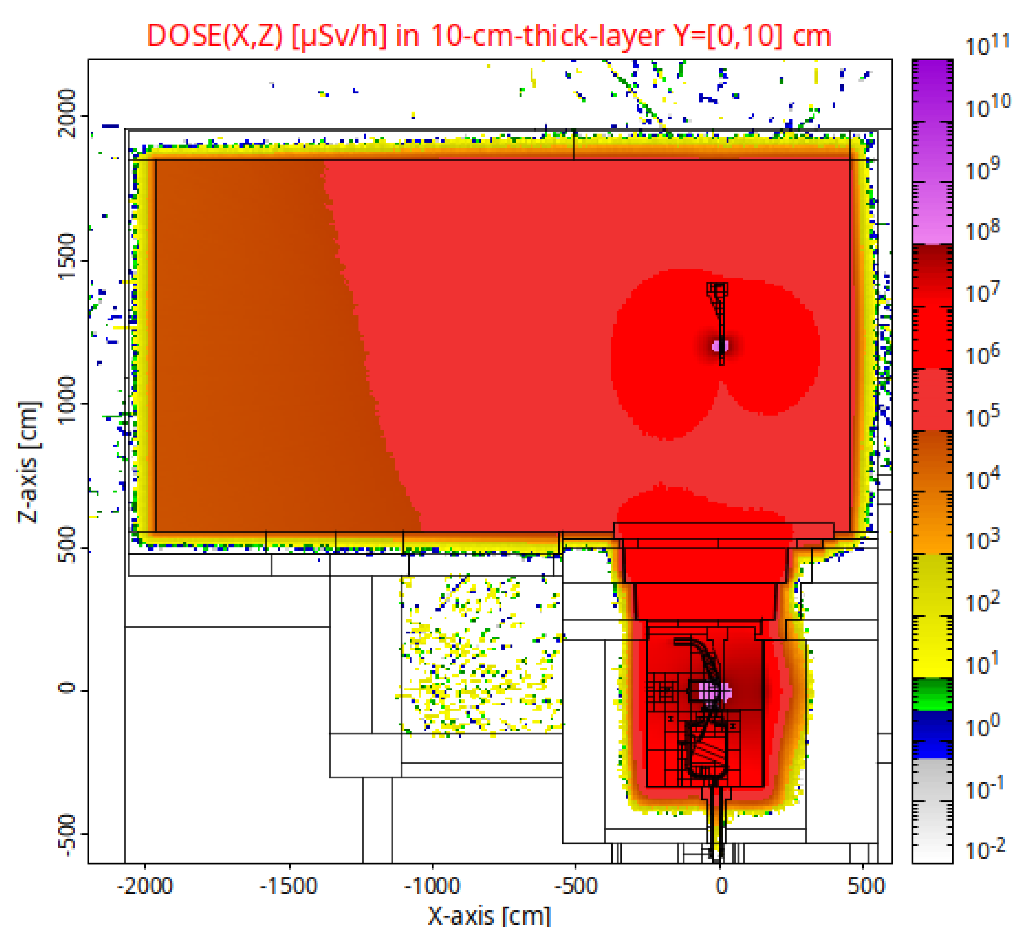
Irradiation maps (direct exposure) are obtained with MCNP and are continuously improved for verification of the irradiation classification, as in Figure 2. Shielding and streamings are computed for verification of areas housing the sources and adjacent ones. A room contamination classification is also developed, taking into account airborne activation and depositions, and sinks according to system operations such as HVAC, filters, and detritiation systems.
The global radiation classification was introduced in [1], and it will take into account both irradiation and contamination subclassifications. Areas are divided into supervised and controlled areas, being the controlled areas subdivided in frequent access, restricted, restricted-special, and forbidden access.
There is an additional classification being devised, closely linked to the contamination one, as it is a ventilation classification according to ISO 17873. This classification also includes considerations of accidental conditions. According to such a classification, the HVAC and argon supply system are designed to provide a network of rooms in the main building with negative gauge pressures, with more potentially contaminated rooms at lower pressures. The discharged effluents must be in compliance with annual dose objectives (presently, estimates are well below the provisional threshold of 50 µSv/year).
Another input for room classification is the operation and maintenance plans of occupancy inside rooms, while the ALARA principle is in consideration. Here, remote handling systems are considered in rooms with higher radiation levels, and criteria for hands-on maintenance of components are defined according to occupation hours: a threshold of 650 µSv/h equivalent dose and 20 µSv/h full body effective dose are being considered at the design stage (assuming a limit of 100 h/year exposure).
There are specific safety-credited systems related to the radioprotection approach. They are explained in the next section.

4. List of Reference Scenarios and Safety-Credited Components

Resulting from FMEA and top-down analysis, a list of reference accident scenarios, RAS, is obtained as a main work-horse for safety activities. Table 1 shows the list of reference accident scenarios identified in SAR_1.0. The list includes 34 scenarios with radiological and nonradiological risks. Others are in discussion and the list may slightly increase in a future version of SAR.
The ‘key’ in the table, the second column, classifies the primary system involved in the scenario (LS for lithium systems, etc.) as well as the type of hazard with the first number: 1 for fires (it may be observed that Li fire risk has several scenarios, and they depend on the potential mass amount involved in scenarios and areas of concern), 2 for explosion/overpower (there are some scenarios related to overpower due to loss of beam energy control), 3 for loss of confinement (related to damage of confinement layers, which often have complex configurations and include specific components), 4 for direct exposure (it is a radiological hazard mostly related to shielding failures or wrong configuration, or it is a chemical hazard related to oxygen displacement and asphyxiation risk), 5 for criticality (not used in DONES), 6 for external hazards (an aircraft impact analysis has been developed with the most probable aircraft), 7 for natural phenomena (where seismic analysis and associated requirements are ongoing).
The second number in the key is a correlative one.
A description is available in the SAR_v1.0 by each of the RAS from two points of view: unmitigated description and mitigated description. The unmitigated description leads to the preliminary conclusion that the risk is not acceptable and must be reduced. The mitigated description should lead to the identification of safety-credited components and features to decrease the risk. Nevertheless, uncertainties are admitted at this stage, and there are ongoing activities to reduce them and consolidate descriptions.
In general, a main objective is to demonstrate that mobilization of radioactive and toxic material in the definitive design-basis scenarios involves small amounts and that only in design extension conditions scenarios can moderate amounts an occur. A short list of design extension conditions accidents is also being developed.
A number of safety-credited components and design features result from RAS analyses and normal operation radioprotection aspects. Some of them are shown in Table 2, which summarizes the present list to implement in design. Nevertheless, others are in discussion. The main examples are further discussed below:
  • Safety beam shutdown will be achieved at the injector by means of two lines of defense: a safety-credited switch in the magnetron electric supply and insertion of a Faraday cup. Differentiation with machine protection actuators is taken into account (in principle, not safety credited in the analysis of scenarios, but in reality providing an additional safety layer on the basis of high reliability and even faster actuation).
  • A fast isolation valve will be placed in HEBT, far enough from high irradiation levels. It will be a component contributing to providing confinement of the TC region, and it will limit air or steam progression to the target from possible breaks in the beam duct.
  • High-reliability inertization to prevent Li fires in postulated spills will be provided by the argon supply system and test cell gas inventory control system. When activated under accident conditions, the confinement function will be coincident with the inertization function.
  • Two electromagnetic pumps in the Li loop will be implemented in compliance with the redundancy requirement (see further explanations in the deterministic analysis section below).
  • A dedicated ‘Personnel Access Safety System’ will prevent the entrance to forbidden access areas or will control access when changed to restricted conditions during maintenance.
  • A ‘Plant Safety System’ (subsystem of ‘Safety Control System’) will provide the beam-shutdown function under a number of safety signals implemented in systems involved in the RAS.
  • The RAMSES will be a dedicated system to provide safety signals related to radiation detection (also linked to beam shutdown) with credited type detectors such as, for instance, in the case of beam mis-steering events.
  • Mechanical codes such as RCC-MRx are systematically revised for application to confinement structures, when possible (pipes, TC liner), to provide robustness in the first line of defense against loss of confinement.
  • Detritiation systems based on conversion to tritiated water and absorption by molecular sieves will take the permeated tritium during normal operation (vent detritiation system) and released tritium in case of accident conditions (emergency detritiation system).

5. Support with Probabilistic and Deterministic Analysis

5.1. Probabilistic Analysis

The application of probabilistic risk analysis (PRA) at the design stage of IFMIF-DONES is challenging, not only because detailed engineering is not fully complete but also because the failure database for innovative components may have gaps in information such as, for example, for accelerator systems components. An implication of this is that the licensing process is expected to be completed following the deterministic approach. However, specific efforts are being made in the project to obtain a database applicable to the facility.
Nevertheless, PRA modeling is a powerful and widely used tool that can precisely inform of a system’s contribution to risk, and its information is very welcome already at design stage because discussions around event trees and fault trees are very helpful. The expectation is to obtain a more mature PRA model over time and to follow risk-informed modifications or required reinforcements if justified in a later stage.
Event trees are being devised in a first step for most of the scenarios, and fault trees behind event trees are being developed in a second step based on the findings from FMEA. Modeling related to fire risk is being prioritized for confirmation of design-basis lines of defense. Examples of developed events are lithium leak from the impurity control system to the test cell, or to the lithium loop cell, but also for other above scenarios, such as lithium flow perturbation, lithium temperature increases, and loss of high-flux test module cooling. Frequencies in the preliminary results are obtained and grouped in moderate, medium, or small releases. Another package of activities addresses several types of confinements, the beam shutdown (to highlight a clear demonstration of high reliability), and detritiation systems. However, work remains to be completed in this area. The next efforts in PRA modeling are oriented to homogenize the available analysis and to consolidate results.

5.2. Deterministic Analysis

Deterministic analyses are being performed for many scenarios. The application of MELCOR code is an important aspect of this activity [5], although analyses are possible with other computational tools (such as MCNP) or even direct modeling. However, MELCOR code is a very convenient tool that allows estimation of key metrics in the progress of scenarios, and hence, they will bound system safety requirements, such as grace periods of time, pressure or temperature peaks in atmospheres and structures, or amounts involved in chemical reactions. The MELCOR-fusion version provides a broad collection of mechanistic models and allows a large flexibility to explore nominal cases and variations, a useful feature in design analysis. A secondary objective is that the MELCOR portfolio of applications is extended, including partial validation exercises, which is an important step to consolidate the code capabilities. It should be mentioned that the applications sometimes run around the limits of code default modeling (for instance, very low pressures, values on the edge of the equation of state). A good level of expertise, however, is a key assumption for code application, and it means that the user should have an appropriate foundation in the phenomenology of safety analysis. As MELCOR-fusion is also used in the fusion safety community (ITER, DEMO), the contribution to user development is another interesting benefit.
The following examples of deterministic analysis warrant mention:
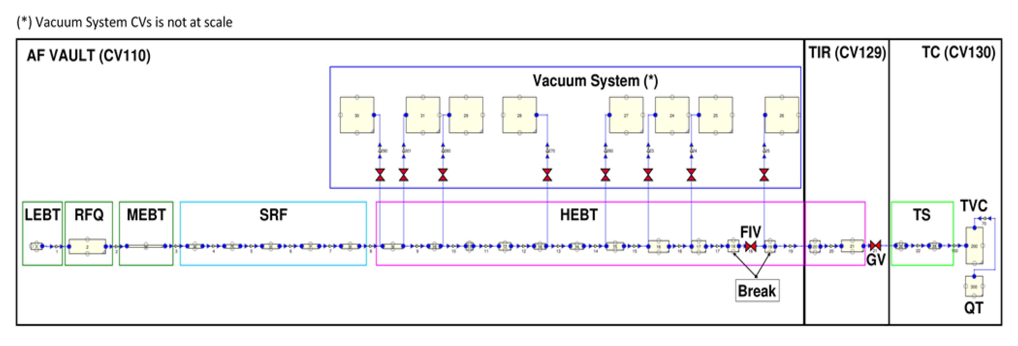
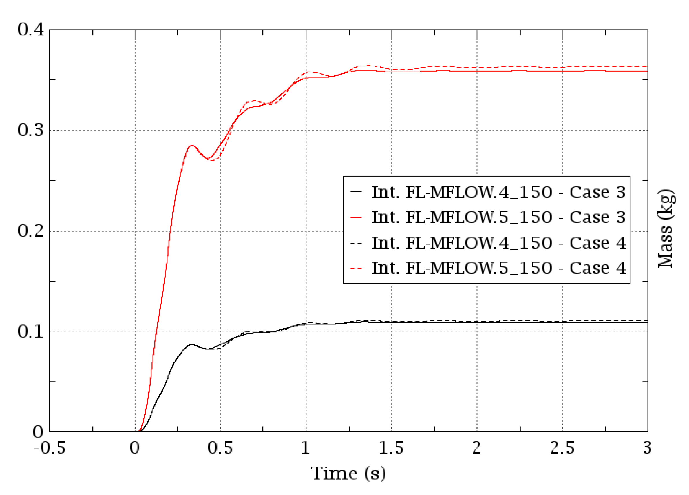
  • RAS12 and 13, beam duct water ingress, and air ingress. A model of the beam duct has been prepared (Figure 3). Duct wall ruptures and the role of FIV is explored to limit the air or water transport towards the target vacuum chamber that could ignite the lithium. Small amounts are obtained (from 0.2 kg to 0.5 kg air, depending on variation in cases and negligible steam, Figure 4). Further mitigation measures are under analysis to reduce such small impact (i.e., extension of inertized Ar region around FIV).
  • RAS1, EMP trip. A model of the Li loop was prepared [5], including prediction of steady-state parameters. Reference calculations were performed for a pump trip in several cases; in one of them the hydraulic power of the pump is reduced to 50%, and it is predicted that the Li layer remains at some 12 m/s, (Figure 5), equivalent to a thick-enough layer to accommodate the beam for an extended period of time before shutdown.
Further applications of MELCOR code are in progress, as is the analysis of Li spill scenarios or a model for main building rooms, together with HVAC performance during normal operation and accident conditions according to leak-path methodologies [6].

6. Experimental Program in Support of IFMIF-DONES Safety

In order to generate knowledge, reduce uncertainties, and demonstrate safety aspects, a number of facilities are expected to be developed or used in upcoming months under the EUROfusion WPENS frame and others:
  • IPUL University of Latvia: EMP prototyping and testing, including transients.
  • NPI Rez: shielding benchmarking with 35 MeV (p, Be) neutron source.
  • RISE Lab, Sweden: Li ignition experiments at small scale.
  • CIEMAT, CDTI FUSION-FUTURE Project: LIFIRE facility for Li ignition and mitigation studies, medium scale. Hardware will be received in 2022 [7].
  • University of Granada: MUVACAS facility. Investigation of beam duct rupture events, role of valves. Recent bidding.
These projects are expected to receive dedicated attention in future months.

7. Conclusions

Safety analysis of IFMIF-DONES has progressed in the last few years, and there is a solid package of information to be followed towards a complete implementation of safety-credited components and features to protect people, the public, workers, and the environment. Some of them are in the phase of implementation by means of interaction with design teams.
The dozens of local safety requirements will be collected in the safety analysis report (and other project documents) and will be part of the licensing process of safety demonstration.
A significant support for confidence in the proposed safety requirements is being obtained with the application of deterministic and probabilistic methodologies using available state-of-the-art tools.
There is still some margin to progress, but it is deemed that most of the analysis and implications can be well established when civil construction of the main building is initiated in the medium term.

Author Contributions

Conceptualization, F.M.-F.; methodology, F.M.-F., J.C.M., T.P., F.O., Y.Q., A.H., S.P. and E.G.; software, F.M.-F., G.D., F.O., Y.Q., S.P., E.G. and M.P.; validation, J.C.M., Y.Q., F.M.-F., G.D. and F.O.; formal analysis, Y.Q., F.M.-F., G.D., T.P., F.O., A.H., S.P., E.G. and M.P.; investigation, Y.Q., F.M.-F., G.D., T.P., F.O., A.G., A.H., S.P. and E.G.; resources, F.M.-F., J.C.M., Y.Q., G.D. and M.P.; data curation, F.M.-F., G.D., T.P., F.O., Y.Q. and E.G.; writing—original draft preparation, F.M.-F., J.C.M.; writing—review and editing, Y.Q., F.M.-F., G.D., T.P., F.O., A.H., S.P. and E.G.; visualization, G.D., F.O., Y.Q. and M.P.; supervision, F.M.-F., J.C.M., A.G. and Á.I.; project administration, F.M.-F., J.C.M., A.G. and Á.I.; funding acquisition, Á.I. All authors have read and agreed to the published version of the manuscript.

Funding

This work was carried out within the framework of the EUROfusion Consortium, funded by the European Union via the Euratom Research and Training Programme (Grant Agreement No. 101052200—EUROfusion). Views and opinions expressed are, however, those of the author(s) only and do not necessarily reflect those of the European Union or the European Commission. Neither the European Union nor the European Commission can be held responsible for them.

Data Availability Statement

Not applicable.

Conflicts of Interest

The authors declare no conflict of interest.

References

  1. Martín-Fuertes, F.; García, M.E.; Fernández, P.; Cortés, A.; D’Ovidio, G.; Pinna, T.; Porfiri, M.T.; Fischer, U.; Ogando, F.; Mota, F.; et al. Integration of Safety in IFMIF-DONES Design. Safety 2019, 5, 74. [Google Scholar] [CrossRef] [Green Version]
  2. Ibarra, A.; Arbeiter, F.; Bernardi, D.; Krolas, W.; Cappelli, M.; Fischer, U.; Heidinger, R.; Martin-Fuertes, F.; Micciché, G.; Muñoz, A.; et al. The European approach to the fusion-like neutron source: The IFMIF-DONES project. Nucl. Fusion 2019, 59, 065002. [Google Scholar] [CrossRef] [Green Version]
  3. Królas, W.; Ibarra, A.; Arbeiter, F.; Arranz, F.; Bernardi, D.; Cappelli, M.; Castellanos, J.; Dézsi, T.; Dzitko, H.; Favuzza, P.; et al. The IFMIF-DONES fusion oriented neutron source: Evolution of the design. Nucl. Fusion 2022, 61, 125002. [Google Scholar] [CrossRef]
  4. Fischer, U.; Bienkowska, B.; Drozdowicz, K.; Frisoni, M.; Mota, F.; Ogando, F.; Qiu, Y.; Stankunas, G.; Tracz, G. Neutronics of the IFMIF-DONES irradiation facility. Fusion Eng. Des. 2019, 146, 1276–1281. [Google Scholar] [CrossRef] [Green Version]
  5. D’Ovidio, G.; Martín-Fuertes, F. Accident analysis with MELCOR-fusion code for DONES lithium loop and accelerator. Fusion Eng. Des. 2019, 146, 473–477. [Google Scholar] [CrossRef]
  6. Louie, D.L.Y.; Humphries, L.L. NSRD-10: Leak Path Factor Guidance Using MELCOR’, SAND2017-3200; Sandia National Lab: Albuquerque, NM, USA, 2017.
  7. D’Ovidio, G.; Martín-Fuertes, F.; Alegre, D.; Marugán, J.C.; Pitigoi, A.; Sierra, J.; Molla, J. CIEMAT experimental proposal on lithium ignition in support of DONES licensing (LiFIRE facility). Nucl. Mater. Energy 2022, 31, 101177. [Google Scholar] [CrossRef]
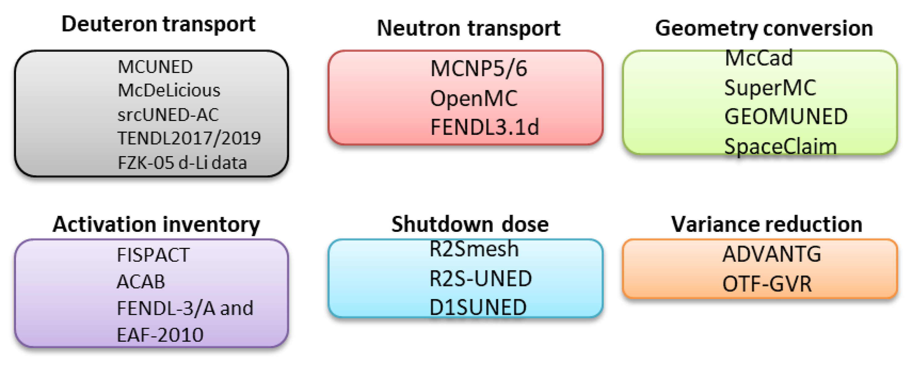
Figure 1. Summary of computational tools for neutronic analyses.
Jne 03 00024 g001
Figure 2. Shutdown dose rate (µSv/h) inside and around the Test Cell (small lower region) and Access Cell (large upper region), 1 week cooldown: the irradiated HFTM module is stationed in the Access Cell, as transported by a crane; the Test Cell is open and activated equipment as Target Assembly and others contribute to the radiation map; an efficient shielding of walls is confirmed.
Jne 03 00024 g002
Figure 3. MELCOR model for accelerator systems events.
Jne 03 00024 g003
Figure 4. Total mass of N2 (red color) and O2 (black color) reaching the TVC volume, 0.05 m2 break downstream FIV. Case 3: vacuum system closed in coincidence with the break; Case 4: VS closed 1.5 s later; Int. FL-MFLOW.X_150 means ‘integrated mass flow through flow path 150 of the MELCOR model’, index X = 4 for O2, X = 5 for N2.
Jne 03 00024 g004
Figure 5. Comparison of Li flow velocities in the target with MELCOR and an analytical prediction Solid blue: simple analytical equations or 0D approach; solid black: base case computed with a circuit MELCOR model and pump trip from 100% to 0% hydraulic power; solid red: same as previous but with an additional reservoir volume at the top of the circuit; dashed red: same as the base case but with a pump trip from 100% to 50% hydraulic power.
Jne 03 00024 g005
Table 1. List of reference accident scenarios in SAR_v1.0 (TBC means ‘to be confirmed’ as analyses progress).
Number of RASKeyDescriptionRisk to Worker (W)/Public (P)
20LS1-1Lithium fire event in LLC areaW/P
21LS1-2Lithium fire event in ICS areaW/P
22LS1-3Lithium fire event in TC areaW/P
23LS1-4Lithium fire event in TC/AC area during maintenanceW
1LS2-1Loss of flow in the Lithium loop due to EMP tripW/P
2LS2-2Loss of heat sink for removal of heat loads from Li loop due to seizure of the secondary loop pumpW/P
3LS3-1Loss of lithium in Lithium loop area due to large break at the electromagnetic pump outletW/P
4LS3-2Loss of lithium in the TC due to large break in piping running inside the cellW/P
5LS3-3Loss of vacuum in target vacuum chamberW/P
6TS3-1Loss of helium gas from HFTM cooling circuit inside TCW/P (TBC)
7TS3-2Loss of flow in the TC-HCS-LP due to spurious valve closureW
8TS3-3Loss of helium gas from HFTM cooling circuit inside the cooling room hosting TS-HCS-LP equipmentW (TBC)
9TS3-4Loss of water flow in the TC-WCS due to spurious closure of isolation valve in the loop hot legW (TBC)
10TS3-5Loss of cooling water from TC-WCS circuit inside the room hosting the TC-WCS equipmentW/P (TBC)
11TS3-6Release towards the environment through TC exhaust due to spurious relief from TC-GICSP (TBC)
24TS3-7Loss of TC liner confinement and tritium release to neighboring roomsW
25TS4-1Direct exposure to TC-WCS pipes running in occupied areaW
26TS4-2Direct exposure due to cracks or gaps in TS shielding blocksW/P (TBC)
27TS4-3Failure of neutron shutter while room occupiedW
12AS3-1Cooling water ingress in the accelerator beam ductW/P (TBC)
13AS3-2Loss of vacuum in beam duct and air ingressW/P (TBC)
14AS2-1Loss of D2 or H2 into the accelerator vault due to rupture of gas supply systemW/P (TBC)
15AS3-3Cryogenic circuit failure and ODH inside accelerator vaultW
28AS2-2Excessive power on the beam dumpW/P
29AS4-1Prompt radiation inside beam enclosure housingW/P (TBC)
30AS4-2Beam mis-steering event or excessive beam spill with consequences outside housingW/P (TBC)
31AS4-3Inadvertent or unauthorized removal of moveable radiation shieldingW
16WM3-1Leakage in liquid radioactive waste treatment systemsW
17WM4-1Failure in solid radioactive waste treatment systemsW
18WM1-1Degradation of radioactive gas treatment systemsW/P
32RH3-1Heavy load fall onto TC floor during replacementW/P (TBC)
33MB1-1Conventional fire event in main buildingW
19MB3-1Loss of negative pressure in activated/inertized roomsW/P
34MB7-1Design-basis seismic eventW/P
35MB6-1Aircraft impact eventW/P
Table 2. List of safety-credited systems or components and design features (safety function in second column can be consulted in ref. [1]).
SIC-1 System, Structure or Component (Examples)Safety FunctionSafety-Credited Features (Examples)
Plant Safety System, PSS (Safety Beam Shutdown)S31st line: Highly reliable cut injector magnetron,
2nd line: Injector Faraday cup (also, HV in seismic event). Precise interface of SCS and MPS to take care.
Redundancy of event detectors in AS, LS, TS, PS, RAMSES
Beam Duct Fast Isolation ValveS3Limitation of air/water progression to target area
Confinement in DBA: 2 valves implementation, fast, slow (in discussion)
Li Loop Heat Removal SystemS3-3-1RCC-MRx for robustness; leak detectors
Redundant EMP (2 pumps)
Test Cell shieldingsS2-1Removable shielding blocks; fixed composition
Test Cell liner/ Lithium Loop Cell linerS1-1Mechanical code RCC-MRx
Tightness as of ISO 16863/Preserve inertization/isolation valves in penetrations
(Li fire aerosol mitigation box in discussion)
Structures for neutron and gamma shielding:
Walls, floors, roofs, doors and penetrations
S2-1Radiation protection in normal op/compliance with radiological classification
Total dose limitation in DB accidents (complementing active beam shutdown)
Personnel Access Safety System, PASSS2-2Control of access for high radiation/hazard areas
Service Gas System (I), TS-GPS:
  • Argon gas for Li loop area
  • Helium gas for TC area
S3-4Inertization as fire protection in DBA (prevention line of defense)
Isolation valves in pipes
Nuclear HVAC:
  • HVAC outlet
  • Outlet HVAC filter
S3-7Negative pressure as of ISO 17873/differential pressure detectors
Dampers for confinement
HEPA filters
Electric Power System for SIC-1 componentsS4-1Redundancy
Vent Gas Detritiation System—Stage 1 (VDS-1)S3-6Compliance with required contamination map
Emergency Detritiation System (EDS)S3-7Redundancy in detection
SCS/ RAMSESS1-2Chipmunk-type neutron detector
Stack monitoring detectors
Tritium detectors for EDS
Publisher’s Note: MDPI stays neutral with regard to jurisdictional claims in published maps and institutional affiliations.