
A Semi-Random Elliptical Movement Model for Relay Nodes in Flying Ad Hoc Networks


Abstract
1. Introduction
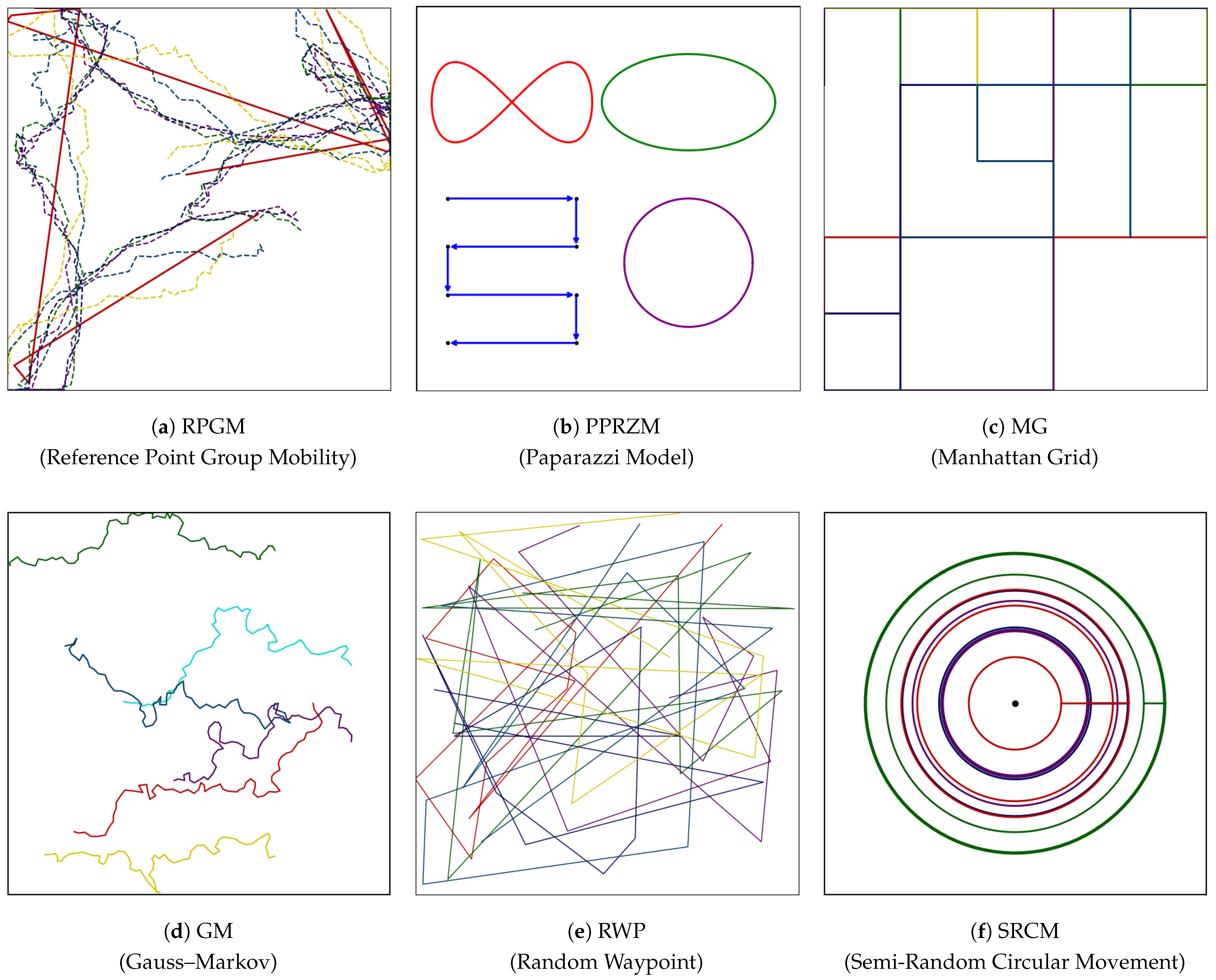
2. Related Work
3. SREM Model
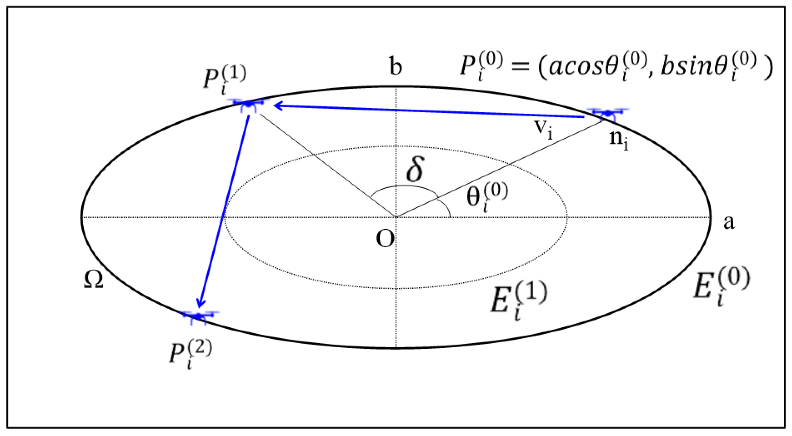
3.1. Design of SREM
- Similarity to real-world navigation: UAVs typically follow straight-line paths using waypoint-based navigation, which aligns with the proposed structure.
- Spatial control with flexible routing: Elliptical boundaries constrain movement, while diverse waypoint combinations enable adaptable paths.
- Simplified analysis: Straight-line movement simplifies distance calculation, relay assessment, and path optimization.
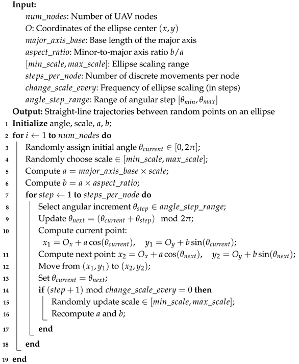
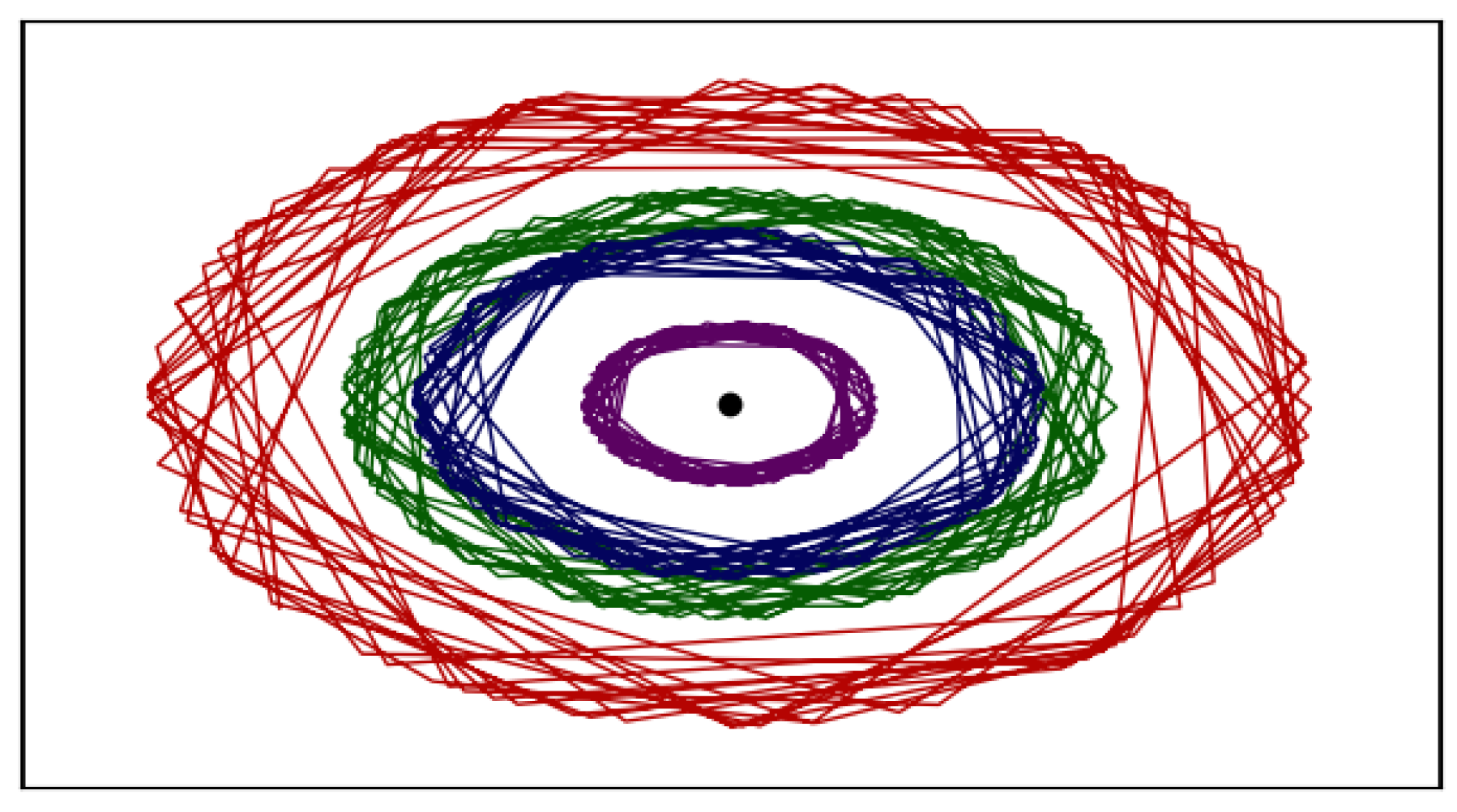
3.2. Implementation of SREM
| Algorithm 1: SREM implementation algorithm. |
 |
3.3. Application of SREM
4. Node Distribution in SREM
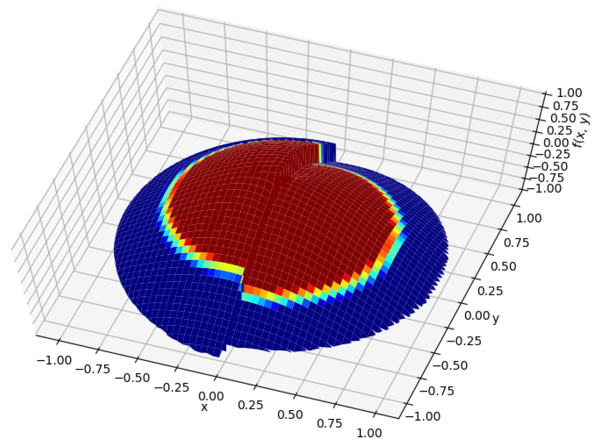
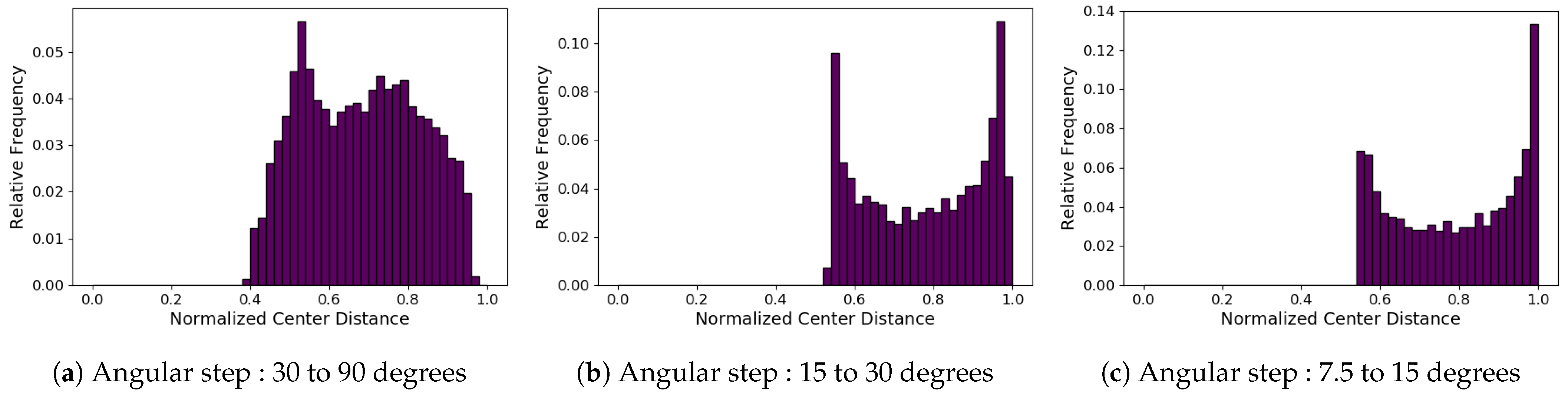
4.1. Numerical Analysis
- : An indicator function that returns 1 if the point lies on the line segment , and 0 otherwise.
- : A weighting factor inversely proportional to the segment length, reflecting that UAVs spend more time on shorter paths.
- : A normalization constant assuming that departure and arrival angles are independently and uniformly sampled along the elliptical perimeter L.
4.2. Empirical Node Distribution
5. Performance Evaluation
5.1. Simulation Setup
- Packet Delivery Ratio (PDR): The ratio of packets successfully delivered to the destination.
- Throughput: The total amount of valid data received per unit time.
- Connection Time (CT): The average duration during which two nodes remain within communication range and maintain a valid routing path simultaneously.
- End-to-End Delay (EED): The time it takes for a packet to travel from the source to the destination.
- Hop Count: The number of hops required for a packet to reach its destination.
5.2. Simulation Results
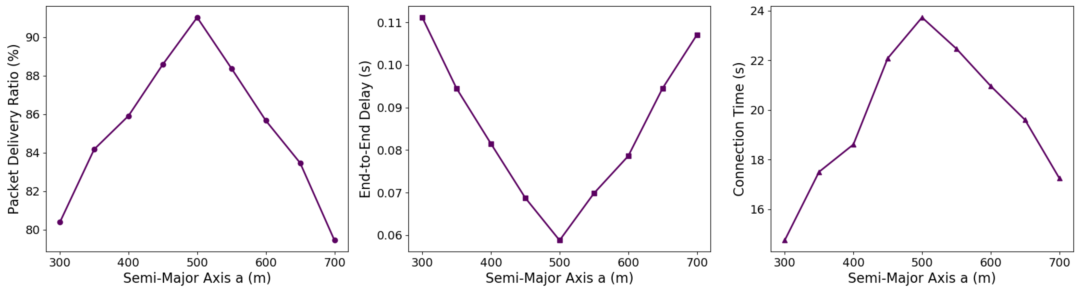
5.3. Sensitivity Analysis of Key SREM Parameters
6. Conclusions
Author Contributions
Funding
Data Availability Statement
Conflicts of Interest
Abbreviations
| FANET | Flying Ad hoc Network |
| UAV | Unmanned Aerial Vehicle |
| SREM | Semi-Random Elliptic Movement |
| SRCM | Semi-Random Circular Movement |
| RWP | Random Waypoint |
| RPGM | Reference Point Group Mobility |
| CLMN | Column Mobility Model |
| ECR | Exponential Correlated Random |
| PPRZM | Paparazzi Mobility Model |
| MG | Manhattan Grid |
| GM | Gauss–Markov |
| ST | Smooth Turn |
| RD | Random Direction |
| RW | Random Walk |
| AODV | Ad hoc On-Demand Distance Vector |
| PDR | Packet Delivery Ratio |
| EED | End-to-End Delay |
| CBR | Constant Bit Rate |
| MAC | Medium Access Control |
| NS-3 | Network Simulator 3 |
| TCP | Transmission Control Protocol |
References
- Pullin, A.; Pattinson, C.; Kor, A.-L. Building Realistic Mobility Models for Mobile Ad Hoc Networks. Informatics 2018, 5, 22. [Google Scholar] [CrossRef]
- Johnson, D.B.; Maltz, D.A. Dynamic Source Routing in Ad Hoc Wireless Networks. In Mobile Computing; Springer: Boston, MA, USA, 1996; pp. 153–181. [Google Scholar]
- Hassan, S.M.; Mohamad, M.M.; Muchtar, F.B. Advanced Intrusion Detection in MANETs: A Survey of Machine Learning and Optimization Techniques for Mitigating Black/Gray Hole Attacks. IEEE Access 2024, 12, 150046–150090. [Google Scholar] [CrossRef]
- Tseng, Y.C.; Hsu, C.S.; Hsieh, T.Y. Power-Saving Protocols for IEEE 802.11-Based Multi-Hop Ad Hoc Networks. Comput. Netw. 2003, 43, 317–337. [Google Scholar] [CrossRef]
- Gossain, H.; Nandiraju, N.; Anand, K.; Agrawal, D.P. Supporting MAC Layer Multicast in IEEE 802.11-Based MANETs: Issues and Solutions. In Proceedings of the 29th Annual IEEE International Conference on Local Computer Networks (LCN’04), Tampa, FL, USA, 16–18 November 2004. [Google Scholar]
- Dureja, A.; Dureja, A.; Khera, M. IEEE 802.11 Based MAC Improvements for MANET. IJCA Spec. Issue MANETs 2010, 2, 54–57. [Google Scholar]
- Patheja, P.S.; Tiwari, V.; Waoo, A.A. An Adaptive MAC 802.11 Protocol for MANET Using Exponential Algorithm. Int. J. Comput. Sci. Inf. Technol. (IJCSIT) 2013, 4, 358–362. [Google Scholar]
- Amponis, G.; Lagkas, T.; Sarigiannidis, P.; Vitsas, V.; Fouliras, P.; Wan, S. A survey on FANET routing from a cross-layer design perspective. J. Syst. Archit. 2021, 120, 102281. [Google Scholar] [CrossRef]
- Choe, H.; Kang, D. ECC Based Authentication Protocol for Military Internet of Drone (IoD): A Holistic Security Framework. IEEE Access 2025, 13, 21503–21519. [Google Scholar] [CrossRef]
- Gu, J.; Su, T.; Wang, Q.; Du, X.; Guizani, M. Multiple Moving Targets Surveillance Based on a Cooperative Network for Multi-UAV. IEEE Commun. Mag. 2018, 56, 82–89. [Google Scholar] [CrossRef]
- Khan, M.A.; Khan, I.U.; Safi, A.; Quershi, I.M. Dynamic routing in flying ad-hoc networks using topology-based routing protocols. Drones 2018, 2, 27. [Google Scholar] [CrossRef]
- Almansor, M.J.; Din, N.M.; Baharuddin, M.Z.; Ma, M.; Alsayednoor, H.M.; Al-Shareeda, M.A.; Al-asadi, A.J. Routing protocols strategies for flying Ad-Hoc network (FANET): Review, taxonomy, and open research issues. Alex. Eng. J. 2024, 109, 553–577. [Google Scholar] [CrossRef]
- Sayeed, M.A.; Kumar, R. An Efficient Mobility Model for Improving Transmissions in Multi-UAVs Enabled WSNs. Drones 2018, 2, 31. [Google Scholar] [CrossRef]
- Yassein, M.B.; Alhuda, N. Flying ad-hoc networks: Routing protocols, mobility models, issues. Int. J. Adv. Comput. Sci. Appl. 2016, 7, 162–168. [Google Scholar] [CrossRef]
- Wheeb, A.H.; Nordin, R.; Samah, A.A.; Alsharif, M.H.; Khan, M.A. Topology-Based Routing Protocols and Mobility Models for Flying Ad Hoc Networks: A Contemporary Review and Future Research Directions. Drones 2021, 6, 9. [Google Scholar] [CrossRef]
- Harri, J.; Filali, F.; Bonnet, C. Mobility Models for Vehicular Ad Hoc Networks: A Survey and Taxonomy. IEEE Commun. Surv. Tutor. 2009, 11, 19–41. [Google Scholar] [CrossRef]
- Ceviz, O.; Sen, S.; Sadioglu, P. A survey of security in uavs and fanets: Issues, threats, analysis of attacks, and solutions. IEEE Commun. Surv. Tutorials 2024. [Google Scholar] [CrossRef]
- Hong, X.; Gerla, M.; Pei, G.; Chiang, C.C. A group mobility model for ad hoc wireless networks. In Proceedings of the 2nd ACM International Workshop on Modeling, Analysis and Simulation of Wireless and Mobile Systems, Seattle, WA, USA, 20 August 1999; pp. 53–60. [Google Scholar]
- Prabhakaran, P.; Sankar, R. Impact of Realistic Mobility Models on Wireless Networks Performance. In Proceedings of the 2006 IEEE International Conference on Wireless and Mobile Computing, Networking and Communications, Montreal, QC, Canada, 19–21 June 2006; pp. 329–334. [Google Scholar]
- Kuiper, E.; Nadjm-Tehrani, S. Mobility Models for UAV Group Reconnaissance Applications. In Proceedings of the 2006 International Conference on Wireless and Mobile Communications (ICWMC06), Bucharest, Romania, 29–31 July 2006; pp. 2–8. [Google Scholar]
- Jayakumar, G.; Ganapathi, G. Reference point group mobility and random waypoint models in performance evaluation of MANET routing protocols. J. Comput. Netw. Commun. 2008, 2008, 860364. [Google Scholar] [CrossRef]
- Bouachir, O.; Abrassart, A.; Garcia, F.; Larrieu, N. A Mobility Model for UAV Ad Hoc Network. In Proceedings of the 2014 International Conference on Unmanned Aircraft Systems (ICUAS), Orlando, FL, USA, 27–30 May 2014; pp. 383–388. [Google Scholar]
- Kalyanam, K.; Casbeer, D.; Pachter, M. Graph Search of a Moving Ground Target by a UAV Aided by Ground Sensors with Local Information. Auton. Robot. 2020, 44, 831–843. [Google Scholar] [CrossRef]
- Sorbelli, F.B.; Pinotti, C.M.; Rigoni, G. On the evaluation of a drone-based delivery system on a mixed euclidean-manhattan grid. IEEE Trans. Intell. Transp. Syst. 2020, 24, 1276–1287. [Google Scholar] [CrossRef]
- Tolety, V.; Camp, T. Load Reduction in Ad Hoc Networks Using Mobile Servers. Master’s Thesis, Colorado School of Mines, Golden, CO, USA, 1999. [Google Scholar]
- Li, Y.; Wang, W.; Gao, H.; Wu, Y.; Su, M.; Wang, J.; Liu, Y. Air-to-Ground 3D Channel Modeling for UAV Based on Gauss-Markov Mobile Model. AEU-Int. J. Electron. Commun. 2020, 114, 152995. [Google Scholar] [CrossRef]
- Dong, Y.; Wu, M. A Smooth-Trajectory Mobility Model for Airborne Networks. In Proceedings of the 2017 20th International Symposium on Wireless Personal Multimedia Communications (WPMC), Bali, Indonesia, 17–20 December 2017; pp. 398–403. [Google Scholar]
- Martinez-Caro, J.-M.; Cano, M.-D. IoT System Integrating Unmanned Aerial Vehicles and LoRa Technology: A Performance Evaluation Study. Wirel. Commun. Mob. Comput. 2019, 1, 1–12. [Google Scholar] [CrossRef]
- Zhong, Z.; Luo, D.; Liu, S.; Fan, X.; Qu, Z. An adaptive localization approach for wireless sensor networks based on Gauss-Markov mobility model. Acta Autom. Sin. 2010, 36, 1557–1568. [Google Scholar] [CrossRef]
- Chiang, K.-H.; Shenoy, N. A 2-D Random-Walk Mobility Model for Location-Management Studies in Wireless Networks. IEEE Trans. Veh. Technol. 2004, 53, 413–424. [Google Scholar] [CrossRef]
- Yoon, J.; Liu, M.; Noble, B. Random Waypoint Considered Harmful. In Proceedings of the IEEE INFOCOM 2003, Twenty-Second Annual Joint Conference of the IEEE Computer and Communications Societies, San Francisco, CA, USA, 30 March–3 April 2003; pp. 1312–1321. [Google Scholar]
- Liu, M.; Wan, Y.; Lewis, F.L. Analysis of the Random Direction Mobility Model with a Sense-and-Avoid Protocol. In Proceedings of the 2017 IEEE Globecom Workshops, Singapore, 4–8 December 2017; pp. 1–6. [Google Scholar]
- Xie, J.; Wan, Y.; Wang, B.; Fu, S.; Lu, K.; Kim, J.H. A comprehensive 3-dimensional random mobility modeling framework for airborne networks. IEEE Access 2018, 6, 22849–22862. [Google Scholar] [CrossRef]
- Wang, W.; Guan, X.; Wang, B.; Wang, Y. A Novel Mobility Model Based on Semi-Random Circular Movement in Mobile Ad Hoc Networks. Inf. Sci. 2010, 180, 399–413. [Google Scholar] [CrossRef]
- Riley, G.F.; Henderson, T.R. The ns-3 Network Simulator. In Modeling and Tools for Network Simulation; Springer: Berlin/Heidelberg, Germany, 2010; pp. 15–34. [Google Scholar]
- Allouch, A.; Cheikhrouhou, O.; Koubâa, A.; Khalgui, M.; Abbes, T. MAVSec: Securing the MAVLink Protocol for ArduPilot/PX4 Unmanned Aerial Systems. In Proceedings of the 2019 15th International Wireless Communications and Mobile Computing Conference (IWCMC), Tangier, Morocco, 24–28 June 2019; pp. 621–628. [Google Scholar]
- Halmos, P.R. The theory of unbiased estimation. Ann. Math. Stat. 1946, 17, 34–43. [Google Scholar] [CrossRef]
- Jiang, D.; Wang, H.; Li, T.; Gouda, M.A.; Zhou, B. Real-time tracker of chicken for poultry based on attention mechanism-enhanced YOLO-Chicken algorithm. Comput. Electron. Agric. 2025, 237, 110640. [Google Scholar] [CrossRef]
- Bekmezci, I.; Sahingoz, O.K.; Temel, Ş. Flying ad-hoc networks (FANETs): A survey. Ad Hoc Netw. 2013, 11, 1254–1270. [Google Scholar] [CrossRef]


| Mobility Model Type | Purpose in Simulation | Representative Models | Experimental Use Cases | Strengths | Limitations |
|---|---|---|---|---|---|
| Group-based | Collaborative flight, swarm, leader-based movement | RPGM, CLMN, ECR | Measure group cohesion, link stability, collision avoidance | Well-suited for formation flying, robust to internal coordination | Not suitable for individual relay testing |
| Planned path | Mission-oriented scanning or patrol with fixed routes | PPRZM, MG | Evaluate coverage uniformity, path efficiency | Realistic mission replication, predictable node paths | Inflexible for dynamic path reconfiguration |
| Time-dependent | Realistic inertia-based directional change | GM, ST | Analyze path continuity, delay fluctuation, connectivity maintenance | Captures motion realism, useful for inertia-based aircraft | Lacks path customization for targeted relay zones |
| Random | Baseline testing, exploratory mobility patterns | RW, RWP, RD | Test routing resilience, assess distribution randomness | Simple to implement, supports wide variability | Poor realism, lacks communication path alignment |
| Feature | SRCM [34] | SREM (Proposed) |
|---|---|---|
| Trajectory shape | Circular path | Elliptical path |
| Movement style | Curved movement along circular arc | Straight-line movement between random points on the ellipse |
| Node speed | Constant angular velocity () | Constant linear velocity (v) |
| Position bias | None | None |
| Purpose | Uniform area surveillance | Relay alignment along the relay axis |
| Flexibility | Limited control over spatial distribution | Directional density adjustable via ellipse parameters |
| Parameter | Value |
|---|---|
| Simulation tool | NS-3 |
| Environment size | |
| Number of UAVs | 50 |
| Mobility model | SREM, SRCM, RWP |
| SREM ellipse (a, b) | |
| SRCM maximum radius | 500 m |
| RWP pause time | 1 s |
| RWP speed | 40 m/s |
| Source node location | |
| Destination node location | |
| Routing protocol | AODV |
| Traffic model | Constant Bit Rate (CBR) |
| Traffic type | TCP |
| Packet size | 64 bytes |
| CBR rate | 1 Mbps |
| HELLO interval | 100 ms |
| MAC protocol | IEEE 802.11a |
| Antenna type | Omni-directional |
| UAV velocity | 20∼40 m/s |
| Simulation runtime | 100 s |
| Mobility Model | PDR [%] | EED [s] | Throughput [KB/s] | CT [s] | Hop Count |
|---|---|---|---|---|---|
| SREM | 91.3 | 0.061 | 110.3 | 23.8 | 11.2 |
| SRCM | 81.4 | 0.089 | 98.1 | 18.1 | 14.5 |
| RWP | 51.7 | 0.175 | 61.0 | 10.4 | 21.7 |
Disclaimer/Publisher’s Note: The statements, opinions and data contained in all publications are solely those of the individual author(s) and contributor(s) and not of MDPI and/or the editor(s). MDPI and/or the editor(s) disclaim responsibility for any injury to people or property resulting from any ideas, methods, instructions or products referred to in the content. |
© 2025 by the authors. Licensee MDPI, Basel, Switzerland. This article is an open access article distributed under the terms and conditions of the Creative Commons Attribution (CC BY) license (https://creativecommons.org/licenses/by/4.0/).
Share and Cite
Choe, H.; Kang, D. A Semi-Random Elliptical Movement Model for Relay Nodes in Flying Ad Hoc Networks. Telecom 2025, 6, 56. https://doi.org/10.3390/telecom6030056
Choe H, Kang D. A Semi-Random Elliptical Movement Model for Relay Nodes in Flying Ad Hoc Networks. Telecom. 2025; 6(3):56. https://doi.org/10.3390/telecom6030056
Chicago/Turabian StyleChoe, Hyeon, and Dongsu Kang. 2025. "A Semi-Random Elliptical Movement Model for Relay Nodes in Flying Ad Hoc Networks" Telecom 6, no. 3: 56. https://doi.org/10.3390/telecom6030056
APA StyleChoe, H., & Kang, D. (2025). A Semi-Random Elliptical Movement Model for Relay Nodes in Flying Ad Hoc Networks. Telecom, 6(3), 56. https://doi.org/10.3390/telecom6030056